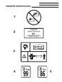
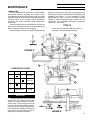
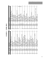
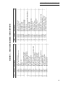
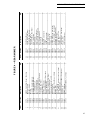
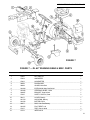
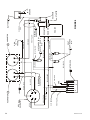
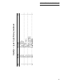
1
68" SR TRIPLEX – CE
OWNER'S MANUAL
Includes Operation, Maintenance and
Parts Lists for SR 68" and DL 68"
NATIONAL MOWER CO.
OCTOBER – 2001
700 Raymond Ave., P.O. Box 14299, St. Paul, Minnesota 55114-0299, U.S.A.
Phone (651) 646-4079 – Fax (651) 646-2887
www.nationalmower.com
NATIONAL MOWER COMPANY
ONE YEAR
LIMITED WARRANTY
For the period of one year from the date of purchase (45 days if the product
is used for rental purposes), National Mower Company will repair or replace free
of charge, for the original purchaser, any part or parts found by inspection to be
defective by our Factory Authorized Service Station or by the Factory at St. Paul,
Minnesota to be defective in material or workmanship or both. All transportation
charges on parts submitted for repair or replacement under this warranty shall be
paid for by the purchaser.
This warranty does not include engines, engine parts or tires which are
covered under separate warranties furnished by their manufacture or supplier.
All service under this warranty will be furnished and performed by our Factory
Authorized Service Stations.
-THERE IS NO OTHER EXPRESS WARRANTYIMPLIED WARRANTIES, INCLUDING THOSE OF MERCHANTABILITY AND
FITNESS FOR A PARTICULAR PURPOSE, ARE LIMITED TO ONE YEAR
FROM PURCHASE OR 45 DAYS IF THE PRODUCT IS RENTED AND TO
THE EXTENT PERMITTED BY LAW, ANY AND ALL IMPLIED WARRANTIES
ARE EXCLUDED. THE ABOVE REMEDY OF REPAIR AND REPLACEMENT
OF DEFECTIVE PARTS IS THE PURCHASER’S EXCLUSIVE REMEDY FOR
ANY DEFECT, MALFUNCTION OR BREACH OF WARRANTY. LIABILITY
FOR INCIDENTAL OR CONSEQUENTIAL DAMAGES UNDER ANY AND ALL
WARRANTIES IS EXCLUDED TO THE EXTENT PERMITTED BY LAW.
NATIONAL MOWER COMPANY
700 Raymond Avenue, St. Paul, Minnesota 55414, U.S.A.
2
68OMCE-10/01-350
®
NATIONAL 68" SR & DL TRIPLEX – CE
TABLE OF CONTENTS
Declaration Of Conformity ............................................................................... 4
Specifications
Dimensions – Mower ................................................................................ 5
Engine – Briggs & Straton ...................................................................... 5
Disposal Numbers .................................................................................... 5
Noise Emission and Vibration .................................................................. 5
Safe Operating Practices ................................................................................ 6
Decal (Transfer) Identification ................................................................... 7 & 8
Introduction ..................................................................................................... 9
Receipt Of Shipment ....................................................................................... 9
Uncrating Instructions ..................................................................................... 9
Assembly Instructions
Rear Mower .................................................................................... 10 & 11
Seat ................................................................................................ 10 & 11
Wing Mowers .................................................................................. 10 & 11
Engine ............................................................................................ 10 & 11
Differential ...................................................................................... 10 & 11
Maintenance
Lubrication .............................................................................................. 13
Bed Knife Replacement .......................................................................... 14
Lapping and Grinding Procedures......................................................... 15
Adjustments
Height Of Cut .......................................................................................... 16
Reel To Bed Knife Adjustment ............................................................... 16
Reel End Play Adjustment ...................................................................... 16
Brake Adjustment ................................................................................... 17
Wing Mower Drive Belt Tension ............................................................. 17
Rear Mower Drive Belt Tension ............................................................. 17
Engine Drive Belt Tension ...................................................................... 17
Main Drive Belt Tension ......................................................................... 17
Troubleshooting ............................................................................................ 18
Wiring Diagram—SR Electrical Interlock ...................................................... 18
Parts List
Ordering Information............................................................................... 19
Frame and Running Gear ............................................................... 20 & 21
Rear End ........................................................................................ 22 & 23
Drive Mechanism and Wing Mower Supports ................................ 24 & 25
Rear Mower .................................................................................... 26 & 27
Wing Mower .................................................................................... 28 & 29
Drive and Mower Skids and Shields ....................................................... 30
Deluxe 68" Running Gear and Misc. Parts ............................................. 31
Deluxe 68" Drive Parts ................................................................... 32 & 33
Deluxe 68" Electrical Diagram ........................................................ 34 & 35
3
DECLARATION OF CONFORMITY
according to Directive 89/392/EEC
We
NATIONAL MOWER COMPANY
..............................................................................................................................................................
(Name of supplier)
700 Raymond Avenue, St. Paul, Minnesota 55114 U.S.A.
..............................................................................................................................................................
(Full address of the manufacturer—authorized representative in the community must also give the
business name and address of the manufacturer)
declare under our sole responsibility, that the product
68" NATIONAL TRIPLEX MOWER
(Make and model)
to which this declaration relates corresponds to the relevant basic safety and health requirements of
the Directive 89/392/EEC, (if applicable)
and to the requirements of other relevant Directives:
EN292-1&2--EN294--EN349
..............................................................................................................................................................
(Title and/or number and date of issue of the other Directives)
(If applicable)
For the relevant implementation of the safety and health requirements mentioned in the directives,
the following standard(s) and/or technical specification(s) has (have) been respected:
ANSI B71.4
..............................................................................................................................................................
(Title and/or number and date of issue of standard(s) and/or technical specification(s))
St. Paul, MN, USA
10/15/2001
(Place and date of issue)
4
(Name, function and signature of the authorized person)
68OMCE-10/01-350
®
NATIONAL 68" SR & DL TRIPLEX – CE
SPECIFICATIONS
DIMENSIONS & WEIGHT– MOWER
Overall Length .............................................................................................. 79.13" (201 cm)
Width, Wing Mowers Folded .......................................................................... 61.8" (157 cm)
Width, Wing Mowers Down ............................................................................... 76" (193 cm)
Height ............................................................................................................ 39.37"(100 cm)
Weight (empty) ......................................................................................... 639.5 lbs. (290 kg)
ENGINE – BRIGGS & STRATTON
Engine Type .............................. Forced Air Cooled, 4-cycle, Horizontal Shaft, OHV Engine
Number Of Cylinders ...................................................................................................... One
Bore and Stroke .......................................................................... 2.99" x 2.17" (76 x 55 mm)
Piston Displacement .................................................................................................... 215cc
Maximum Horsepower .................. 7.5 hp (5.6 kW)) / 3600 rpm (Corrected per SAE J1349)
Maximum Torque ............................................................ 12.5 ft/lbs (16.5 N-m) at 2500 rpm
Direction Of Rotation ............................................ Counterclockwise Facing The PTO Shaft
Fast Idle Speed .......................................................................................................4000 rpm
Slow Idle Speed ......................................................................................................1750 rpm
Fuel ............................................................................................ Unleaded Gasoline (Petrol)
Fuel Tank Capacity .................................................................................... 4.80 US qt (4.54)
Minimum Specific Fuel Consumption Ratio ............................... 240 gr/hp-hr (322 gr/kW-hr)
Oil ................................................................................................... Engine Oil SAE 10W-30
Oil Capacity .................................................................................................. 1.90 US pt (.90)
Carburetor ............................................................................. Float Type with Fixed Main Jet
Balancing ......................................................................................... Reciprocating Balancer
Ignition .......................................................................... Flywheel Magneto, Transistor Type
Spark Plug ...................................................................................................... Resistor Type
Starter ................................................. Recoil Starter with Automatic Compression Release
Governor ............................................................................................................. Mechanical
Lubrication Type .......................................................... Splash with Low Oil Shut-off System
Air Cleaner ....................................................................................................... Dual Element
Muffler ........................................................................................................... Low Tone Type
Lighting Coil ......................................................................................................... 12 V–25 W
Charging Coil ................................................................................................................. 10 A
Net Weight (Engine) .................................................................................. 59.1 lbs (26.8 kg)
Dimensions (L x W x H) ........................... 13.5" x 15.6" x 17.0" (344.5 x 395.5 x 432.5 mm)
DISPOSAL NUMBERS
Gasoline (Petrol), Lead Free ....................................................................................... 54104
Engine Oil .................................................................................................................... 54112
Fiberglass Parts ........................................................................................................... 57103
Tires ............................................................................................................................. 57502
Gear Oil ........................................................................................................................ 54112
Grease ......................................................................................................................... 54202
Plastic Tanks ................................................................................................................ 57127
NOISE EMISSION AND VIBRATION
Sound*:
Operator Position ...................................................................................... 86 dBA
Sound Power Level (LwA) ........................................................................ 99 dBA
Vibration*: Maximum Vibration 16.1 m/s2 RMS
Location ................................................................................................ Left Hand
*Operating Condition: Engine rpm–3400, Unit Stationary
5
IMPORTANT
National Mower Safe Operation Practices
For Riding Mowers
1. Know control functions and how to stop quickly. READ THE OWNER’S MANUAL.
2. Wear approved safety glasses or goggles when operating the mower.
3. Do not allow children to operate mower. Do not allow adults to operate mower without proper
instruction.
4. Do not carry passengers. Keep children and pets at a safe distance from an operating mower.
5. Clear the work place of objects which might be picked up by the blades and thrown.
6. Disengage all reel clutches and shift into neutral before attempting to start the engine (motor). Disengage main
clutch before shifting reel clutches.
7. Disengage power to the reels and stop the engine (motor) before leaving the operator’s position.
8. Disengage power to the reels and stop the engine (motor) before making any repairs or adjustments.
9. Disengage power to the reels when transporting or not in use.
10. Take all possible precautions when leaving the mower unattended, such as, shifting into neutral, setting the
parking brake, stopping the engine and removing the ignition key.
11. Do not stop or start suddenly when going uphill or downhill. Mow up and down the face of steep slopes – never
across steep slopes. Do not exceed a slope of 25o in any direction.
12. Reduce travel speed on slopes and in sharp turns to prevent tipping or loss of control. Use extreme caution
when changing direction on slopes.
13. Watch for holes in the terrain and other hidden hazards.
14. Watch for dangerous traffic when crossing or near roadways.
15. Never direct the discharge of material from operating reels toward bystanders nor allow anyone near the mower.
16. Handle gasoline (petro)l with CAUTION - it is highly flammable.
a.
Use an approved gasoline (petrol) container.
b.
Never remove the fuel tank cap or add gasoline (petrol) to a running or hot engine. Never fill the fuel tank
indoors. Wipe spilled gasoline (petrol) immediately.
c.
Open garage doors to allow ventilation if engine is run inside – exhaust fumes are dangerous. Do not run
engine in any enclosed area.
17. Keep the mower in good operating condition. Make sure that all safety switches are operating properly and
all safety guards are in place at all times, except during servicing.
18. Keep all nuts, bolts, and screws tight to be sure that the mower is in a safe working condition.
19. Never store the mower, with gasoline (petrol) in the tank, inside a building where fumes could reach an open flame
or spark. Allow the engine to cool before storing in any enclosure.
20. Keep the engine free of grass, leaves or excessive grease to reduce a fire hazard.
21. The mower and reels should be stopped and inspected for damage after striking a foreign object. The damage
should be repaired before restarting and operating the mower.
22. Do not change the engine governor settings or overspeed the engine.
23. Proceed as follows when mowing:
a.
Mow only in the daylight or in good artificial light.
b.
Never make a cutting height adjustment while the engine (motor) is running.
c.
Shut the engine (motor) off when removing grass or unclogging reels.
24. This machine is to be used only as a grass cutter or lawn mower.
WARNING– California, USA residents are required by law (CA PRC 4442 & CA H & SC 13005) to equip their
engines with spark arresters when operating in flammable vegitation. Arresters must be obtained from your
engine dealer and are not available from National Mower Company.
6
68OMCE-10/01-350
®
NATIONAL 68" SR & DL TRIPLEX – CE
TRANSFER IDENTIFICATION
1
2
NATIONAL MOWER CO.
700 RAYMOND AVE.
ST. PAUL, MINNESOTA 55114 USA
651-646-4079
FAX 651-646-2887
YEAR OF MANUFACTURE: 2000
POWER RATING: 7.5 (5.6 kW) at 3600 RPM
WEIGHT: 639.5 lbs (290 kg)
3
4
5
7
6
7
8
NO.
1
2
07358
07358
3
07358
away
4
5
8
PART NO.
07363
07363
6
07359
7
07359
8
07359
9
07359
9
TRANSFER DESCRIPTION
Do not exceed 25o slope. Located on main belt shield.
Manufacturer's identification and specifications. Located
on the main belt shield.
Read Operator's Manual. Refer to manual for adjustments.
Caution: Machine is used only as a lawn mower. Keep
bystanders. Located on main belt shield.
Sound power level. Located on main belt shield.
Sound Level, operator's position. Located on main belt
shield.
Forward, Neutral and Reverse positions. Located on main
belt shield.
Rear mower clutch engagement. Located on the rear
mower shield.
Wing mower clutch engagement. Located on main belt
shield.
Engine clutch lever: Back, Neutral & Forward. Located on
main belt shield.
68OMCE-10/01-350
®
NATIONAL 68" SR & DL TRIPLEX – CE
INTRODUCTION
This machine has been designed to meet European
CE Safety Standards. Metric eqivalents are provided
wherever possible for users outside the United States.
This manual has been prepared by National Mower
Company as an aid to users for assembly, maintenance,
adjustment and ordering replacement parts. Additional
information will gladly be furnished by calling or writing the
manufacturer or his authorized agent.
Please furnish us with the Model Number, Serial
Number and Date of Purchase when contacting us about
your machine. Designations of right, left, front and rear
are used as if the operator was sitting in the mower seat.
RECEIPT OF SHIPMENT
Carefully inspect your machine and crate for damage that could have occured during shipment. If damages
or shortages are noted, have the transportation company’s
representative note this on the bill of lading.
NOTE
Claims for shipping damages must be noted by the
consignee at the point of destination and filed with the
transportation company that delivers the shipment.
UNCRATING INSTRUCTIONS
In order to prevent possible damage to the machine or
personal injury, the following uncrating procedure must
be followed:
1. Position Crate 1 as shown in Figure A, on a hard, level
surface.
2 Cut and remove all Steel Banding (2, Fig. A).
3. Remove the entire top of the crate. Unbolt Seat (3,
Fig. A) from crate bracing and lay seat aside for
installation later. Save the bolt and washer to use for
mounting the seat mounting member.
4. Lift Rear Mower (4, Fig. A) off the crate supporting
members and set aside for later attachment.
CAUTION
CAUTION
Handle mowers carefully with protective gloves.
Reels rotate freely and are very sharp.
5. Make sure Wing Mowers (5, Fig. A) are secure to the
mower frame with Wing Mower Hooks (15, Fig. B).
6. Knock down all sides of crate and remove. Roll mower
backwards off of crate base.
FIGURE A
9
FIGURE B
10
68OMCE-10/01-350
®
NATIONAL 68" SR & DL TRIPLEX – CE
ASSEMBLY INSTRUCTIONS
REAR MOWER
WING MOWERS
1. Remove two 1/2" x 1-1/2" Hex Head Bolts (1, Fig. B)
and nuts from the shipping position in the Seat Hinge
assembly (2, Fig. B). Position Seat Hinge Assembly
with pivot facing rearward, over the seat mount of the
mower frame and fasten with Bolts (1, Fig. B) and lock
nuts.
1. Remove Wing Mower Belts (17, Fig. B) from the steering column.
2. Pivot Seat Brace (3, Fig. B) from the axle so that the
top end aligns with the tab at the back of the seat
hinge assembly. Fasten with a 5/16" x 1" Hex Head
Bolt, Lock Washer and Hex Nut.
3. Remove the Lifter Tee (4, Fig. B) from the shipping
position in the Pivot Tube (5, Fig. B) and set aside
cotter pin and washer for later use. Insert the rod end
of lifter tee through the slotted hole in the pad on the
rear mower frame and secure with the cotter pin and
washer as shown.
4. Fasten Rear Mower Pull Rod (6, Fig. B) inner leg by
removing Bolts (7, Fig. B) and reinserting it through
pull rod and attaching flanges on tractor axle. Note
that Spacers (8, Fig. B) must be in each pivot point to
allow free movement of the pull rod.
5. Attach Pull Rod (6, Fig. B) to Pivot Tube (9, Fig. B) with
Pin (3, Fig. K on page 17) and Spacers (1, Fig. K).
NOTE: Before completing assembly, it will be necessary to refer to the rear Mower Drive Belt Tension
section and Figure K, page 17 for adjusting belt
tension.
6. Install Rear Mower Belt (10, Fig. B) from Countershaft
Pulley (11, Fig. B) to outer Drive Pulley (12, Fig. B).
Idler Pulley (13, Fig. B) must ride on top of lower belt
to provide proper tension. NOTE: It will be necessary
to raise rear mower to allow enough slack to get belt
over pulleys.
2. Unlock Hooks (18, Fig. B) from Wing Mower Assemblies (19, Fig. B), lower them carefully to the ground.
Slip wing mower belts over Countershaft Pulleys (20,
Fig. B).
3. Block mower wheels to prevent mower from moving
forward. Pull Wing Mower Assemblies (19, Fig. B)
forward so that they slide on Pull Rods (21, Fig. B) and
compress springs. This will allow enough slack to
enable belts to be installed over Reel Pulleys (22, Fig. B).
ENGINE
MOWER IS SHIPPED WITH DRY ENGINE. DO
NOT START ENGINE UNTIL OIL IS ADDED TO
CRANKCASE. See Engine Manual for additional
information.
DIFFERENTIAL
Grease has been installed in the differential at the
factory. Refer to the Maintenance Section, page 7, for
additional information.
SEAT
1. Fasten Seat (15, Fig. B) to seat mounts by threading
four 5/16" x 1" Hex Bolts (16, Fig. B), through 5/16"
lockwashers, through holes in seat mounts and into
the threaded holes in the bottom of the seat.
11
OPERATION
FIGURE C
The following is a description of the machine controls
and their function. Refer to Figure C.
1. Engine Clutch Lever (labeled Mowing Clutch) –
Engages power for travel and mowing. Down position is
disengaged and up position is engaged. IMPORTANT –
Engage slowly before full engagement. Always disengage
the drive when stopping or leaving the machine. See
Caution Decal.
The engine clutch lever has an electrical interlock and
engine will not start if clutch is engaged. For added safety,
the interlock system should be checked periodically to
ensure that it is adjusted to function properly.
2. Wing Mower Clutch – Engages drive to wing mowers.
Pull lever back and down to engage. Never engage drive
unless wing mowers have been lowered to cutting position.
3. Ignition Key Switch – Provides a means to secure the
mower when unattended. Turn the key clockwise to
unlock the ignition.
4. Throttle Control – Regulates mowing and travel speeds.
Moving the control handle back or lowering it will reduce
engine speed for starting and idling engine. Push forward
to increase engine speed. Never operate mower at speeds
faster than necessary to do a good, safe job.
5. Brake – Is designed to slow the mower and lock the rear
wheels in the full stop position. Depress the foot pedal to
engage. Note: It is best to slow the mower with the throttle
and then disengage clutch lever before applying brake.
This prevents excessive wear and engine overload.
12
6. Parking Brake Lever – Provides a lock for the brake.
Push brake lever forward, over center, to lock. Pulling
brake lever back, toward the rear of the machine will
disengage the brake.
7. Shifter Lever – Located on the mower differential, this
control has three positions: Forward, Neutral (center
position), and Reverse. The lever must be pulled toward
the center of the machine to clear the notch in the stop disc
and positioned securely in the new notch.
IMPORTANT: Never shift while machine is in motion
because it could cause damage to the gears. Always
disengage engine clutch before attempting to shift.
8. Rear Mower Clutch Shifter Lever – Engages drive
to the rear mower. Pull lever forward and toward the
center of the machine to engage sliding jaw clutch. To
disengage, pull lever forward and out to engage locking
pin. Never engage the drive unless the rear mower has
been lowered to the cutting position.
9. Rear Mower Lifter Handle – Raises rear mower to the
transport position. Pull handle up, forward and over center
to lock it in an up position.
10. Wing Mower Lifter Handles – Raises wing mower to
the transport position. Lift wing mowers until they can be
secured with hooks on frame.
Moving machinery can be dangerous if not operated
properly. Follow all safe operating suggestions listed on
Safe Operation Practices, Page 6.
68OMCE-10/01-350
®
NATIONAL 68" SR & DL TRIPLEX – CE
MAINTENANCE
LUBRICATION
Figure D shows the top view of the 68" Triplex Mower
with guards removed. Lubricate the machine at the
recommended locations and intervals using the proper
lubicants to ensure maximum service and long life of your
machine. Refer to the engine manual (separately
furnished) for proper lubrication and maintenance
instructions.
Since the mower does not operate at high speeds, the
grease level in the differential is not critical providing that
there is sufficient grease to coat the gears.
Unless leakage is evident, it is recommended that the
grease be checked once each year. Check grease level
by loosening the bolts in the differential case flanges and
spreading case halves. It is not necessary to totally
disassemble the case or remove the wheels for this
inspection. Add Multi-purpose Gear Grease such as
Pennzoil No. 303 or equivalent if necessary. Total grease
capacity is 1-1/2 pounds.
Do not use oil in the differential case in place
of grease–it will leak through the seals.
FIGURE D
LUBRICATION CHART
ITEM
GREASE
OIL
FEQUENCY
1
8 Hours
2
8 Hours
3
30 Hours
4
Gear Grease
Yearly
IMPORTANT
Figure E shows the top view of the left
wing mower with guards removed and
shows the proper lubrication locations.
These areas on both wing mowers must
be free of dirt and grass clippings and be
well lubricated for proper drive belt tension and operation. Support collars for the
wing mower pull rods must be kept in
alignment to maintain belt tension.
FIGURE E
13
BED KNIFE REPLACEMENT
When the bed knife becomes damaged or too worn to
keep sharp, it must be replaced. Design improvements
have made bed knife replacement easier with bolt-on
construction. Follow the procedure below.
1. The backbar (1, Fig. F), bed knife (2, Fig. F) and
fasteners have been assembled at the factory under
tension. To ease replacement and prevent misalignment of components, the leading edge of the backbar
must be tack welded two or three places before the old
fasteners are removed.
2. Remove shoulder nuts (3, Fig. F) and flat head
screws (4, Fig. F). If shoulder nuts are badly rusted or
corroded, they may have to be cut off and screws
driven out to be removed.
3. Clean the bottom surface of the backbar for
maximum metal contact with the new bed bar.
4. Fasten the new bed knife to the bottom of the
backbar in the position shown (bent edge up). Shoulder of shoulder nuts must be seated firmly in the
backbar and screws must be flush with the bottom of
the bed knife.
5. Torque shoulder nuts 35 to 40 ft/lbs.
FIGURE F
14
68OMCE-10/01-350
®
NATIONAL 68" SR & DL TRIPLEX – CE
LAPPING PROCEDURE
INTRODUCTION
Back lapping is a very important step in maintaining sharp
reel blades on the rear and wing mowers.
This procedure should be performed when the reel blades
and the bed knife become slightly rounded and the grass
is not cut cleanly with only a slight bed knife adjustment.
Also, after grinding the bed knife and reels, you should
back lap to establish a perfect match between the bed
knife and reel blades.
RECOMMENDED STEPS
1. Adjust the bed knife to the reel so that the bed knife is
level with the reel and light contact is maintained.
2. Reels must be run in a reverse direction to be lapped.
Remove the lower drive belts and attach a back lapping
machine (not supplied by National Mower) to the reels.
Follow the instructions furnished by the machine manufacture.
3. Apply the lapping compound with the reels running,
using a 2" or a 3" brush. Apply the compound evenly to the
moving blades.
Many types of compounds are available for lapping.
However, we recommend a good pre-mixed water soluble
compound. Many different grit ranges are available. Premixed compound saves the time required to mix, eliminates
the waste of abrasive, rinses off easily with water and is
available in all grit ranges from course to extra fine.
4. Stop the reel and examine both bed knife and reel
blades to see that the cutting edges are uniformly sharp.
If not, gradually tighten the reel adjuster bolts (see Figure
I, Page 16) and repeat Step 3 untill the proper sharpness
results.
5. Rinse off the compound thoroughly with water to
remove all abrasive. Check for sharpness and readjust
the bed knife if necessary. Reel to bed knife contact
should be adjusted to easily cut a sheet of paper (see
Adjustments, Page 16 for detailed instructions).
Be extremely careful not to let the brush, your
fingers or your clothing get caught in the reels.
Use approved safety glasses to protect your
eyes from flying particles and abrasives.
GRINDING
BACK GRIND IN THE
DIRECTION
OF THE ARROW AT 25O
Reels must be ground at 25° in the direction shown below
by the arrow in Figure G. Back grind until reel blades are
free from roundness, dents and nicks. Spin grind to
remove all burrs. All blades must be on the same diameter.
For maximum cutting efficiency, grind bed knife top and
front edges at 5° as shown in Figure H.
25O
GRIND BED KNIFE
AT ANGLES SHOWN
5O
5O
Note centerline
FIGURE G
POSITION OF
REEL
TO THE BLADE
FIGURE H
15
ADJUSTMENTS
To ensure safety, all of the following adjustments must be made only after the engine
clutch lever has been disengaged and the
ignition key and spark plug wire have been
removed.
HEIGHT OF CUT
The height of cut is variable and may be adjusted on
both wing mowers and the rear mower by loosening the
top and bottom Adjusting Nuts (1, Fig. I) which hold Roller
Adjusters (2, Fig. I) in Roller Brackets (3, Fig. I). Roller (4,
Fig. I) may then be moved up and down.
It is important to get all rollers adjusted to the same
height so that there will be uniform cutting across the
NOTE
Guards removed or cut
away to show detail
entire width of the mower. Do not adjust by sight. Place the
mower on a hard, level surface. Loosen the Adjusting
Nuts (1, Fig. I) on each side of reel assemblies and place
a board or gauge plate of the desired height under each
bed knife back bar. Tighten bolts securely.
REEL TO BED KNIFE ADJUSTMENT
The reel is adjusted to a fixed position bed knife. This
construction allows a more rugged and durable frame and
retains the proper adjustment longer. The Reel Adjuster
Bolt (5, Fig. I) regulates reel distance from the bed knife.
To reduce the distance, turn the upper hex adjuster nut
on each side of the reel down. Proceed slowly and do not
overadjust—use about 1/8 of a turn on each side at first.
Do not adjust one side more than the other unless the reel
is obviously out of alignment. Do not get the reel so tight
that it is hard to turn by hand. A too tight reel will wear much
faster. Ideally, the reel should “wipe” or lightly touch the
bed knife. It is not necessary to adjust or change the
position of the lower adjustment nut.
Proper cutting action may be tested by holding paper
strips between the reel and the bed knife. Turn the reel by
hand and check to see if the assembly cuts the paper all
the way across the width of the bed knife. Make sure that
the adjusting and the locking nuts on both side are
tightened securely.
Handle reel assemblies carefully with
protective gloves.
Reels rotate freely and are very sharp.
Special care should be taken in the area
where the reel contacts the bed knife.
REEL END PLAY ADJUSTMENT
With extended use, normal wear of the reel bearings
will cause end play. This condition could cause uneven
wear to mower parts and uneven cutting of turf.
FIGURE I
16
Test for end play periodically by trying to move the reel
from side to side in the frame. If there is ANY movement,
adjust the bearings by loosening the lock nut on the
adjustment bolt (6, Fig. I) which is located on the inside
right end of the reels, and turning the adjustment bolt IN
one half turn or less. Do not overtighten. An overtightened
bearing will cause excessive bearing wear. Test again for
end play and if reel is rotating freely and end play is not
noticeable, tighten the lock nut.
68OMCE-10/01-350
®
NATIONAL 68" SR & DL TRIPLEX – CE
BRAKE ADJUSTMENT
The foot brake is properly adjusted if it slows the
machine when depressed and can be locked when the
pedal is depressed fully.
NOTE
Guards removed
to show detail
Adjust brake tension by removing cotter pin and brake
pedal pin and turning brake clevis located under pedal on
brake rod. When adjustment is complete, attach clevis to
pedal with pin and cotter pin.
WING MOWER DRIVE BELT TENSION
Proper Belt tension allows mowers to be driven without
slippage but loose enough to be deflected slightly at a
point midway between the pulleys. An overtight belt will
cause excessive bearing wear and a slipping belt causes
excessive belt wear. IMPORTANT: Never allow oil to get
on the belt which could cause slipping.
FRONT
OF
MACHINE
Adjust tension by loosening set screw (Fig. E) in the
wing mower pull arm, sliding the mower rearward and
retightening set screw.
REAR MOWER DRIVE BELT TENSION
Follow the recommendations above for determining
proper tension and refer to Figure J.
Spacers (1, Fig. J) are provided on the rear mower Pull
Rod (2, Fig. J) to adjust the belt tension. Remove Pin (3,
Fig. J) from the end of the pull rod and slip out the pull rod
from the Pivot Tube (4, Fig. J). Move as many spacers as
necessary to the location indicated and reassemble.
ENGINE DRIVE BELT (Engine to Main Countershaft)
Belt tension is increased by loosening the four engine
mounting bolts and sliding the engine forward in the
slotted frame holes. Test for the proper tension as detailed
FIGURE J
for the wing mower adjustment. When tension is correct,
tighten all the bolts securely.
MAIN DRIVE BELT (Main Countershaft to Rear Drive)
Belt tension is increased by loosening the four bolts
holding the Main Countershaft Housing (45, Fig. 3) and
sliding the housing forward in the slotted frame holes.
NOTE - It will probably be necessary to loosen or remove
belt guards to reach the adjustment bolts. Also, if this belt
is adjusted, it will probably be necessary to readjust the
engine belt.
17
TROUBLE-SHOOTING
Tractor Unit
Situation
Things To Check
Engine will not start
Turn ignition switch to on
Ensure that there is sufficient gasoline (petrol) in the tank
Make sure safety switch is making contact and mowing clutch is down
Look for a loose wire on Ignition or spark plug wire not connected
Operator must be positioned on seat to depress presence switches
Interlock system inoperative—check wiring, see Figure K
Tractor will not move
forward
Gear selector must be in one of the drive positions
Engine drive clutch must be engaged (rearward and up)
Drive belts too loose (see page 17)
Visually check to see that pulleys are not slipping on shafts
If everything above is OK, check for a damaged gear in the gear box
Tractor will not move
rearward
Same as above. If all of the above check OK, check the reverse gear in the
gear box
Tractor will not stop
Ensure that the main clutch is disengaged (brake will not stop engine)
Brake adjustment or service may be needed (see page 17)
Cutting Units
Situation
Things To Check
Wing and/or rear mower will not cut
Bed knife to reel position may be out of adjustment (see page 16)
Drive belts or drive chains may need tightening
Visually check that both the drive pulleys and the shafts are rotating
Cutting units will not turn.
Clutches may not be engaged
Look for anything that could be jammed between the reel and the bed knife
Drive belts or drive chains may need tightening
Visually check that both the drive pulleys and the shafts are rotating
Units will not stop turning
Disengage all clutches
Uneven cut
Height of cut not the same on each cutting unit (see page 16)
Check to see if any part is bent
Something jammed in cutting unit pivots, not allowing them to float
Electrical System (DL 68" only) Check wiring connections and switch operation—see Figure 9, page 34
All adjusting must be made with the engine off.
Do not do any investigation of the working parts of the machine with the motor running.
Always turn the engine off!
18
68OMCE-10/01-350
®
NATIONAL 68" SR & DL TRIPLEX – CE
INTERLOCK
OPERATOR PRESENCE
SWITCH N/O
07035
CONNECTOR
TO
KEY
SWITCH
Yellow
INTERLOCK
MODULE ASSY.
204988
ABCDEF
Red
GROUND
Yellow
Brown
NEUTRAL START
SWITCH N/O
07035
Black
OPERATOR
PRESENCE
SWITCH N/O
07035
Yellow
Black
ENGINE
FIGURE K
PARTS LIST
Note: For your records and future ordering, fill in the following information.
DATE PURCHASED
MODEL NO.
SERIAL NO.
ORDERING INFORMATION
When ordering replacement parts, always furnish:
1. Your complete name, address and phone number.
2. Model Number and Serial Number (stamped on the main frame
rear axle gusset below seat).
3. Part Number (it is recommended that the correct number be verified
with a current Master Price List).
4. The full Description of the part.
5. Quantity desired (quantity shown is the total number of parts contained in the particular view shown).
If the Part Number and the Description of your order do not
agree, the Part Number will be used to fill your order.
19
20
68OMCE-10/01-350
WHEN ORDERING, STATE THE MODEL AND SERIAL NUMBERS OF THE MOWER
FIGURE 1
Part No.
Description
Qty.
SEAT MOUNT
1
1
200818
FRAME
1
2
200002
REAR TIRE & WHEEL ASSEMBLY
2
3
07018
________________________________________________________________________________________________________________________________________
FOOT REST, Left Hand
1
4
200085
BUSHING, Axle Pivot
2
5
201961
BUSHING, Spindle and Steering Post
6
6
06002
_______________________________________________________________________________________________________________________________________
DRAG LINK
1
7
09014
KING PIN, Left Hand
1
8
200193
TIRE & WHEEL
2
9
07038
________________________________________________________________________________________________________________________________________
SHAFT, Steering
1
10
200094
AXLE ASSEMBLY, Front
1
11
200186
TIE ROD
1
12
201851
______________________________________________________________________________________________________________________________________________
PIN, Clevis Tie Rod
1
13
04003
KING PIN, Right Hand
1
14
200196
BUMPER, Front
1
15
200033
____________________________________________________________________________________________________________________________________________
BEARING, Wheel Hub
4
16
06112
DUST CAP, 3/4'’ I.D.
2
17
02602
DUST CAP, 7/8'’ I.D.
2
02603
______________________________________________________________________________________________________________________________________________
CLEVIS, Threaded, Tie Rod
1
18
200863
PEDAL, Brake
1
19
200104
SWITCH, Safety
1
20
07035
_____________________________________________________________________________________________________________________________________________
FOOT REST, Right Hand
1
21
200139
SWITCH, Interlock
1
22
204988
GUARD, Main Belt
1
23
09016
________________________________________________________________________________________________________________________________________________
Not used
—
24
—
STEERING WHEEL
1
25
200200
SEAT
1
26
07036
_____________________________________________________________________________________________________________________________________________
COLLAR, Steering Shaft
1
27
200199
THROTTLE CONTROL, (Includes conduit and wiring)
1
28
07032
BRACKET, Throttle Control
1
29
200203
______________________________________________________________________________________________________________________________________________
SWITCH, Key, Briggs & Stratton and Kawasaki
1
30
07034
HINGE, Seat
2
31
200814
SPRING, Seat
2
32
04512
______________________________________________________________________________________________________________________________________
DECALS (Transfers) for CE Models — See Pages 7 & 8
AR
33
---------BALL JOINT
2
34
200867
SWITCH, Seat
2
35
07035
_______________________________________________________________________________________________________________________________________
BRACKET, Seat Switch
1
36
204987
Item
FIGURE 1 — FRAME & RUNNING GEAR
NATIONAL 68" SR & DL TRIPLEX – CE
®
21
22
68OMCE-10/01-350
WHEN ORDERING, STATE THE MODEL AND SERIAL NUMBERS OF THE MOWER
FIGURE 2
Part No.
Description
Qty.
1
1
04502
SPRING, Shifter Lever
2
1
200675
BUSHING, Shifter Lever Bushing
_______3
________________200064
__________________________SHIFTER
____________________LEVER
_________________________________________________________________________1
_____
4
1
07007
GRIP, Shifter
5
1
04021
CLEVIS, Brake
6
04022
PIN,
Brake
Pedal,
3/8"
x
1-1/4"
______________________________________________________________________________________________________________________________________________1
_____
7
1
200061
STOP DISC, Shifter
8
1
200103
ROD UNIT, Brake
9
06102
BEARING,
Countershaft
_________________________________________________NEEDLE
___________________
_____________________Rear
___________
__________________________________________2
_____
10
1
08010
U-BOLT, Shifter
11
1
201432
BRACKET,Parking Brake Pull
_____12
__________________08037
__________________________ROD,
____________Formed,
_________________Parking
________________Brake
________________________________________________1
_____
13
1
201433
LEVER, Parking Brake
14
1
200676
BUSHING
BEARING,
_____15
__________________06101
__________________________NEEDLE
___________________
_____________________Intermediate
_________________________Shaft
____________________________2
_____
16
1
07003
GASKET, Back Plate Cover
17
1
200234
COVER, Differential Case, Inside
18
200051
SLIDING
WASHER,
Differential
Case
_____________________________________________________________________________________________________________________________________________1
_____
19
1
04008
PIN, Spring (Roll PIn), 5/16" x 1-1/8"
20
1
200054
GEAR, Shifting, 11 Tooth
21
200050
_________________________________________________GEAR,
_______________Reverse
______________________________________________________________________________1
_____
22
1
06003
BUSHING, Reverse Gear
23
1
200049
SHAFT, Reverse Gear
_____24
__________________200069
__________________________PINION,
_________________Differential
____________________________________________________________________________4
_____
25
1
07009
GASKET SET, Differential
26
1
200065
COVER, Differential Case, Outside
_____27
__________________200079
__________________________HUB,
____________Rear
__________Wheel,
_______________Right
________________________________________________________1
_____
28
2
06005
BUSHING, Rear Wheel Hub
29
1
200680
DUST WASHER, 1-1/8"
30
03504
O-RING,
1-1/8"
______________________________________________________________________________________________________________________________________________1
_____
31
1
200084
SPLIT DISC SEAL, Wheel Hub, Right Rear
32
1
03503
SEAL, Oil
34
200075
_________________________________________________AXLE
____________ASSEMBLY,
__________________________Rear
_______________________________________________________1
_____
35
2
06004
BUSHING, Bull Gear
Item
Part No.
Description
Qty.
1
RETAINING RING, Pinion gear
36
09012
1
BULL GEAR ASSEMBLY, Complete
200066
37
Intermediate
____38
_________________200070
___________________________SHAFT
_______________UNIT,
_____________
__________________________________________________________________1
_____
1
WASHER, 1-1/8" I.D.
39
02607
1
SLEEVE, Axle Bearing
200088
40
BEARING,
Right
Axle
06103
41
______________________________________________________________________________________________________________________________________________1
_____
1
SPACER, Right Axle
42
02510
1
SEAL, Rear Axle
03510
43
WASHER,
Bearing,
Left
Axle,
1-1/8"
02510
44
______________________________________________________________________________________________________________________________________________1
_____
1
BEARING, Left Axle
45
06104
AR
SHIM, Left Axle, 10 Ga.
200687
46
_____________________200821
___________________________SHIM,
_____________Left
________Axle,
___________14
______Ga.
_____________________________________________________AR
________
AR
SPACER, Left Axle, 1/32"
47
200685
AR
SHIM, Axle Spacer, 22 Ga.
200688
____48
_________________200095
___________________________COLLAR,
___________________Rear
___________Axle
________________________________________________________________1
_____
1
CAP, Left Axle
49
200096
1
WHEEL HUB, Left Rear
200090
50
1____
PIN,
Collar,
Rear
Axle,
1/4"
x
1-3/4"
51
04016
______________________________________________________________________________________________________________________________________________
4
KEY, Woodruff, #11
04013
52
1
LOCK RING, 7/8"
04020
53
BRAKE
BAND
ASSEMBLY
54
200099
______________________________________________________________________________________________________________________________________________1
_____
1
O-RING, 7/8"
03502
55
1
DUST CAP, 7/8"
02603
56
____57
_________________03618
___________________________PULLEY,
___________________Step
___________________________________________________________________________1
_____
1
BRAKE DRUM
200097
58
1
KEY, Woodruff, #9
04012
59
____60
_________________200055
___________________________SHAFT,
________________Shifting
_________________Countershaft
_____________________________________________________________1
_____
1
LOCK RING, 3/4"
04011
61
1
LEVER, Brake Band
200102
62
DUST
CAP,
3/4"
63
02602
______________________________________________________________________________________________________________________________________________1
_____
1
O-RING, 3/4"
03511
64
1
COUNTERSHAFT CARRIER UNIT, Shifting
200056
65
CARRIER,
Shifter
66
200063
______________________________________________________________________________________________________________________________________________1_____
1
BUSHING, Shifter Lever
200676
67
Item
FIGURE 2 — REAR END
NATIONAL 68" SR & DL TRIPLEX – CE
®
23
FIGURE 3
WHEN ORDERING, STATE THE MODEL AND SERIAL NUMBERS OF THE MOWER
24
68OMCE-10/01-350
Part No.
Description
Qty.
1
07023
GRIP, Lever, '96 and up
1
2
200167
LEVER, Lower Countershaft Control
1
______3
_______________200170
________________________ROD
______________________________________________________________________________________1
_____
4
200182
COLLAR, Lock
2
5
04503
SPRING
2
6
Idler
_____________________200172
________________________ROD,
___________Countershaft
________________________
________Control
__________________________________________1
_____
7
200655
HOOK, Wing Mower, Left Hand
1
200656
HOOK, Wing Mower, Right Hand
1
8
_____________________200137
________________________PULL
___________ANGLE,
________________Wing
__________Mower,
______________Rear
___________________________________1
_____
9
07226
GRIP, Wing Mower Arm
2
10
201880
PIN, Wing Mower Arm
2
11
______________________200151
_________________________PULL
____________ROD,
___________Wing
___________Mower
________________________________________________________2
_____
12
02602
DUST CAP, 3/4" I.D.
4
13
PULL ARM, Wing Mower, Left and Right Hand 2
201536
14
Wing
04505
_______________________________________________SPRING,
__________________
__________Mower
_____________Pull
________Rod
_______________________________________2
_____
15
CARRIER, Lower Countershaft
200128
1
16
PULLEY, Lower Countershaft
03615
2
17
Countershaft
06105
_______________________________________________BEARING,
_____________________Lower
_____________
________________________________________________________2
_____
18
BELT GUIDE, Pulley
200136
1
19
PULLEY, Lower Countershaft Drive
03603
1
20
Countershaft,
03901
_______________________________________________BELT,
_____________
_________________________A29
___________________________________________________1
_____
21
COUNTERSHAFT, Lower
200135
1
22
PULLEY, Countershaft Idler
03607
1
23
03608
________________________________________________IDLER,
_______________Engine
______________Clutch
______________________________________________________________2
_____
24
ARM, Engine Clutch
200179
1
1
Item
Part No.
Description
Qty.
200176
25
ARM, Countershaft Idler
1
200173
26
BRACKET, Idler Pivot
1
_________27
___________202445
_________________________STUD,
_____________Belt
________Guide
_________________________________________________________________1
_____
201541
28
BELT GUIDE, Lower
1
201538
29
BELT GUIDE, Upper
1
_________30
___________200165
_________________________ROD,
___________Main
_________Clutch,
______________Upper
___________________________________________________1
_____
08021
31
ROD, Main Clutch, Lower
1
03609
32
PULLEY, Motor
1
Rated
_________33
___________03903
_________________________BELT,
____________Engine,
_______________Kawasaki,
___________________6844
__________Gates
____________
__________________1
_____
200208
34
KEY, Square, Engine,
1
200184
35
ARM, Main Belt Idler
1
_________36
____________04501
__________________________SPRING,
__________________Main
__________Belt
_________Idler
_________Arm
____________________________________________1
_____
200163
37
LEVER, Engine Clutch
1
07024
38
KNOB, Clutch Lever
1
GUARD,
_________39
___________09002
___________________________
________________Engine
______________Clutch
__________________________________________________________1
_____
03606
40
PULLEY, Main Countershaft
1
200157
41
COUNTERSHAFT, Main
1
_________42
____________03902
__________________________BELT,
_____________Drive,
____________B66
_________________________________________________________________6
_____
04013
43
KEY, Woodruff, #11
2
06006
44
BUSHING, Main Countershaft Housing
1
200154
_________45
____________
__________________________HOUSING,
_____________________Main
__________Countershaft
__________________________________________________________1
_____
200158
46
STEP PULLEY, Main Countershaft
1
07037
47
TRANSFER SET, 68" Triplex - CE
1
200530
48
GUIDE, Belt, High Speed Pulley
_____________________________________________________________________________________
Item
FIGURE 3 — DRIVE MECHANISM & SIDE SUPPORTS
NATIONAL 68" SR & DL TRIPLEX – CE
®
25
26
68OMCE-10/01-350
FIGURE 4
NOTE—Skids and Reel
End Shields are not
shown. See Figure 6
WHEN ORDERING, STATE THE MODEL AND SERIAL NUMBERS OF THE MOWER
Part No.
Description
Qty.
1
09170
GUARD, Clutch, Rear Mower, '96 and up
1
2
201513
BRACKET, Shield
2
______
_______________________UPRIGHT,
__________________Shield
______________________________________________________________________
3_______________200235
2____
4
203173
ROLLER
1
5
302847
ADJUSTER, Roller Bracket, L.H.
1
_____________________
_______________________ADJUSTER,
_____________________
__________Bracket,
______________R.H.
__________________________________________
302846
Roller
1____
6
203248
ROLLER BRACKET, L.H.
1
7
200109
PULL YOKE, Rear Mower
1
______
_______________________REEL
___________
________________ASSEMBLY
_____________________________________________________________
8_______________200236
TAKE-UP
2____
9
200256
ADJUSTING SCREW & NUT, Bearing
2
10
200237
PIVOT TUBE, Rear Mower
1
____11
__________________
________________________COUNTERSHAFT
___________________________________________________________________________________________1
_____
200263
12
06006
BUSHING, Countershaft
2
13
201735
REEL CARRIER ASSEMBLY, Right Hand
1
____14
_________________201437
_________________________
__________________
________Bearing
_______________________________________________________________2
_____
TAKE-UP,
Reel
15
200261
HOUSING, Countershaft, Rear Mower
1
16
03116
SPROCKET, Countershaft
1
____17
__________________
________________________PIN,
________Sprocket
________________Hub,
_________5/16"
__________x___
_____________________________________________1
_____
04008
1-1/8"
18
03115
SPROCKET, Reel
1
19
200241
REEL ASSEMBLY, Rear Mower, 6 Blade
1
____20
_________________06120
_________________________BEARING,
___________________
_______________________________________________________________________2
_____
Reel
06121
CUP, Reel Bearing
2
21
02109
SCREW, Bed Knife (sold as a set with nut below)
9
______________________201802
_________________________NUT,
__________Bed
_______Knife
__________Screw
_________________________________________________________________9
_____
22
201773
BED KNIFE FRAME ASSEMBLY, Rear Mower
1
23
201407
BED KNIFE, 30"
1
____24
_________________04549
_________________________SPRING,
________________Adjusting
__________________________________________________________________________2
_____
25
201734
REEL CARRIER ASSEMBLY, Left Hand
1
Item
Part No.
Description
Qty.
26
200223
FRAME, Rear Mower
1
27
07481
CHAIN, Roller, Rear Mower
1
_______28
_______________203452
________________________LIFTER
______________TEE,
_________Rear
_________Mower
___________________________________________________________1_____
29
200214
BRACKET, Guard
1
30
202251
LIFTER HANDLE, Rear Mower
1
_______31
_______________07039
_________________________GRIP,
___________Lifter
__________Handle
_______________________________________________________________________1_____
32
202301
BRACE, Seat
1
33
202249
PIVOT TUBE, Rear Mower
1
YOKE,
_______34
_______________200271
_________________________SHIFTER
_________________
____________Rear
_________Mower
_____________________________________________________1_____
35
03905
BELT, Rear Mower, A42
1
36
200388
SHIFTER LUG
1
Clutch
_______37
_______________05022
________________________PIN,
_________
__________________________________________________________________________________2_____
38
200273
BRACKET, Clutch Lever
1
39
202438
SPRING
1
Shifter
_______40
_______________200276
_________________________LEVER,
_______________Clutch
____________
__________________________________________________________________1_____
41
07022
GRIP, Shifter Clutch
1
42
02602
DUST CAP, 3/4" I.D.
1
_______43
_______________04506
_________________________SPRING,
_________________Clutch
____________________________________________________________________________1_____
44
200266
CLUTCH, Sliding Jaw, Rear Mower
1
45
200264
PULLEY ASSEMBLY, Countershaft
1
_______46
_______________06007
_________________________BUSHING,
___________________Countershaft
______________________Pulley
__________________________________________________1_____
47
200123
BUSHING, Pull Yoke
2
48
203172
ROLLER BRACKET, R.H.
1
Idler
_______49
_______________04504
________________________SPRING,
_________________
__________________________________________________________________________1_____
50
200115
IDLER ARM UNIT, Rear Mower
1
51
03607
PULLEY, Idler
1
_______52
______________201519
_______________________SHIELD,
_______________Rear
________Mower
_______________________________________________________________1
_____
Item
FIGURE 4 — REAR MOWER
NATIONAL 68" SR & DL TRIPLEX – CE
®
27
FIGURE 5
28
68OMCE-10/01-350
®
NATIONAL 68" SR & DL TRIPLEX – CE
FIGURE 5 — WING MOWERS
Item
Part No.
Description
Qty.
1
201513
BRACKET, Shield
4
2
200235
UPRIGHT, Shield
4
3
203250
ROLLER
2
________________________________________________________________________________________________________________________________________
4
203248
ROLLER BRACKET, L.H.
2
5
302847
ADJUSTER, Roller, L.H.
2
302846
ADJUSTER,
Roller,
R.H.
2
_______________________________________________________________________________________________________________________________________
6
201775
FRAME, Bed Knife, Bolt-on
2
7
201460
SCREW, Flat Head
14
201802
NUT, Bed Knife Screw
14
________________________________________________________________________________________________________________________________________
8
201504
BED KNIFE, 21",
2
9
04549
SPRING, Reel Adjusting
2
10
200236
REEL TAKE-UP ASSEMBLY
4
______________________________________________________________________________________________________________________________________________
11
201734
REEL CARRIER ASSEMBLY, Left Hand
2
12
06120
BEARING, Reel, (Includes Race)
4
13
200296
REEL ASSEMBLY, 6 Blade
2
____________________________________________________________________________________________________________________________________________
14
201781
FRAME, Wing Mower
2
15
200256
ADJUSTING SCREW & NUT, Bearing
2
16
201437
TAKE-UP
WASHER,
Reel
Bearing
2
______________________________________________________________________________________________________________________________________________
17
201383
CAP SCREW (Special), Pulley Scraper
2
18
200287
PULLEY SCRAPER
2
19
201735
REEL CARRIER ASSEMBLY, Right Hand
2
_____________________________________________________________________________________________________________________________________________
20
03932
BELT, A35, Wing Mower
2
21
03601
PULLEY
2
22
201520
SHIELD, Right Hand
1
________________________________________________________________________________________________________________________________________________
201521
SHIELD, Left Hand
1
23
203172
ROLLER BRACKET, R.H.
2
29
FIGURE 6
FIGURE 6 — SKIDS, REEL END SHIELDS & GUARDS
Item
Part No.
Description
Qty.
1
203728
SKID BAR, L.H.
1
2
202959
SHIELD, Wing Mower
3
3
201585
SKID, Mower
2
4
203727
SKID BAR, R.H.
2
5
202410
GUARD, Inside, Rear Mower
1
6
202281
CHAIN GUARD, Rear Mower
1
___________________________________________________________________________________________________________________________________________________________
30
68OMCE-10/01-350
®
NATIONAL 68" SR & DL TRIPLEX – CE
FIGURE 7
FIGURE 7 — DL 68" RUNNING GEAR & MISC. PARTS
Item
Part No.
Description
Qty.
1
07065
KEY SWITCH
1
2
07064
AMPMETER
1
3
07063
HOURMETER
1
________________________________________________________________________________________________________________________________________
4
09098
DASHBOARD
1
5
09099
GUARD, Main Belt
1
6
201994
EXTENSION,
Main
Belt
Shield
1
_______________________________________________________________________________________________________________________________________
7
201996
STEERING WHEEL, DL68
1
8
204987
BRACKET, Seat Switch
1
9
07035
SAFETY SWITCH, Seat
2
_________________________________________________________________________________________________________________________________________
10
09101
COVER, Battery
1
11
201754
HOLDOWN, Battery
1
12
201582
BATTERY BOX
1
______________________________________________________________________________________________________________________________________________
13
08057
ROD, Side Post Battery
2
14
201925
FOOT REST, Left
1
15
07237
TIRE, Deluxe Wide
2
___________________________________________________________________________________________________________________________________
16
07572
INTERLOCK
1
31
FIGURE 8
FIGURE 8 — DL 68" DRIVE PARTS
Item
Part No.
Description
Qty.
1
09100
GUARD, Engine Clutch
1
2
201881
RETAINER, Mowing Belt
1
3
201884
RETAINER, Transport Belt
1
________________________________________________________________________________________________________________________________________
4
201890
MOUNT, Belt Guides
1
5
201872
STEP PULLEY, Main Countershaft
1
6
03603
PULLEY, Transport, Main Countershaft
1
_______________________________________________________________________________________________________________________________________
7
02507
Washer, 10 GA.
2
8
03502
O-RING, 7/8" Dia.
2
9
06101
NEEDLE
BEARING
2
_________________________________________________________________________________________________________________________________________
10
03902
BELT, Drive, B66
1
11
03655
PULLEY, Main Countershaft
1
12
04013
KEY, Woodruff, #11
3
______________________________________________________________________________________________________________________________________________
13
201871
COUNTERSHAFT, Main
1
26
32
68OMCE-10/01-350
®
NATIONAL 68" SR & DL TRIPLEX – CE
Item
Part No.
Description
Qty.
14
201740
HOUSING, Main Countershaft
1
15
200208
KEY, Square, Engine
2
16
03926
BELT, Engine, Transport, 6841 Gates Power Rated
1
________________________________________________________________________________________________________________________________________
17
202071
PULLEY, Engine, Transport Belt
1
18
03903
BELT, Engine, Mowing, 6844 Gates Power Rated
1
19
03609
PULLEY, Engine, Mower Belt
1
_______________________________________________________________________________________________________________________________________
20
202780
BELT GUIDE WELDMENT, Engine
1
21
202446
STUD, Belt Guide
1
22
201946
BRACKET, Idler Pivot with Bushings
1
_________________________________________________________________________________________________________________________________________
23
200530
GUIDE, Belt
1
24
202441
SPRING, Transport Pedal Return
1
25
03608
PULLEY, Idler
1
______________________________________________________________________________________________________________________________________________
26
201721
FOOT LEVER
1
27
201728
ARM, Idler, Lower Countershaft
1
28
201730
ARM.,
Idler,
Mowing
Belt
1
____________________________________________________________________________________________________________________________________________
29
03607
PULLEY, Clutch Lever
1
30
201718
PULLEY LEVER, Transport
1
31
201889
GUIDE, Belt
1
____________________________________________________________________________________________________________________________________
32
201919
ROD, Transport Clutch
1
33
202440
SPRING, Transport
1
34
201966
PEDAL, Transport
1
____________________________________________________________________________________________________________________________________
35
200135
COUNTERSHAFT, Lower
1
36
201926
CARRIER, Lower Countershaft
1
33
34
68OMCE-10/01-350
G
L
#516 YELLOW
#501 BROWN
#501 BLUE
Y
E
L
L
O
W
B A
LEAD
M
S
#510 YELLOW
#506
ORANGE
KEY
SWITCH
HOURMETER
B
R
O
W
N
B R B B
L E L L
U D A A
E / C C
B K K
L
K
GRN.
#501 RED
#506 ORANGE
GROUND
HARNESS
#512 RED
#512 WHITE
#510 YELLOW
#501 BRN.
SEAT
SWITCHES
N/O
#501 BLACK
BATTERY
#515 RED
6 GA.
FIGURE 9
ENGINE
MAGNETO
REGULATOR
WIRING
HARNESS
#516 YELLOW
CLUTCH NEUTRAL
SAFETY SWITCH
N/O
#516 YELLOW
#501 BLACK
INTERLOCK
#501 BLACK
#501 BROWN
#511 RED
#512 WHITE
GRN.
TO
FRAME
AMPMETER
STARTER
SOLENOID
GROUND
Part No.
Description
Qty.
1
07065
KEY SWITCH
1
2
07063
HOURMETER
1
3
07064
AMPMETER
1
________________________________________________________________________________________________________________________________________
4
N.A.
BATTERY
1
5
07104
GROUND, Battery
1
6
07217
LEAD
1
_______________________________________________________________________________________________________________________________________
7
07216
HARNESS ASSEMBLY
1
8
07035
SWITCH, Clutch Safety
3
9
07572
INTERLOCK
M585
1
_________________________________________________________________________________________________________________________________________
10
07571
WIRING HARNESS
1
Item
FIGURE 9 — DL 68" ELECTRICAL DIAGRAM
NATIONAL 68" SR & DL TRIPLEX – CE
®
35
36
68OMCE-10/01-350