1
Matrox Meteor-II
Installation and Hardware Reference
Manual no. 10577-101-0300
December 9, 1999
Matrox® is a registered trademark of Matrox Electronic Systems Ltd.
Microsoft®, MS-DOS®, Windows®, and Windows NT® are registered
trademarks of Microsoft Corporation.
Intel®, Pentium®, and Pentium II® are registered trademarks of Intel
Corporation.
Texas Instruments is a trademark of Texas Instruments Incorporated.
PC/104-Plus™ is a trademark of the PC/104 Consortium.
CompactPCI™ is a trademark of PCI Industrial Computer
Manufacturers’ Group.
RAMDAC™ is a trademark of Booktree.
All other nationally and internationally recognized trademarks and
tradenames are hereby acknowledged.
© Copyright Matrox Electronic Systems Ltd., 1999. All rights reserved.
Disclaimer: Matrox Electronic Systems Ltd. reserves the right to make
changes in specifications at any time and without notice. The
information provided by this document is believed to be accurate and
reliable. However, no responsibility is assumed by Matrox Electronic
Systems Ltd. for its use; nor for any infringements of patents or other rights
of third parties resulting from its use. No license is granted under any
patents or patent rights of Matrox Electronic Systems Ltd.
PRINTED IN CANADA
Contents
Chapter 1: Introduction . . . . . . . . . . . . . . . . . . . . . . . . . . . 9
Matrox Meteor-II boards . . . . . . . . . . . . . . . . .10
Matrox Meteor-II /Standard . . . . . . . . . . . .10
Matrox Meteor-II /Multi-Channel . . . . . . . .11
Matrox Meteor-II /Digital . . . . . . . . . . . . . .13
Matrox Meteor-II /1394 . . . . . . . . . . . . . . .14
Matrox Meteor-II MJPEG module . . . . . . . .15
Data transfer . . . . . . . . . . . . . . . . . . . . . . .16
Software . . . . . . . . . . . . . . . . . . . . . . . . . . .16
What you need to get started. . . . . . . . . . . . . .18
Inspecting the Matrox Meteor-II package. . . . .19
Standard package. . . . . . . . . . . . . . . . . . . .19
Optional items . . . . . . . . . . . . . . . . . . . . . .19
Handling components. . . . . . . . . . . . . . . . .20
Installation overview . . . . . . . . . . . . . . . . . . . .21
Chapter 2: Hardware installation . . . . . . . . . . . . . . . . . . 23
Installing Matrox Meteor-II . . . . . . . . . . . . . . .24
Installing Matrox Meteor-II for PCI . . . . . . .24
Installing Matrox Meteor-II for
CompactPCI . . . . . . . . . . . . . . . . . . . . . . . .27
Installing Matrox Meteor-II for
PC/104-Plus . . . . . . . . . . . . . . . . . . . . . . . .29
Installing the Matrox Meteor-II
MJPEG module . . . . . . . . . . . . . . . . . . . . . . . .31
Connecting external devices . . . . . . . . . . . . . . 33
Matrox Meteor-II /Standard for PCI . . . . . . 33
Matrox Meteor-II /Standard for
CompactPCI. . . . . . . . . . . . . . . . . . . . . . . . 36
Matrox Meteor-II /Multi-Channel for PCI . . 37
Matrox Meteor-II /Standard and
/Multi-Channel for PC/104-Plus . . . . . . . . 39
Matrox Meteor-II /Digital. . . . . . . . . . . . . . 40
Matrox Meteor-II /1394 . . . . . . . . . . . . . . . 42
Chapter 3: Installing software . . . . . . . . . . . . . . . . . . . . . 45
Installing the software . . . . . . . . . . . . . . . . . . 46
Note about Matrox Intellicam . . . . . . . . . . . . . 46
Chapter 4: Using multiple Matrox Meteor-II boards . . 47
Using multiple Matrox Meteor-II boards . . . . . 48
Multiple board installation . . . . . . . . . . . . . . . 48
Grabbing simultaneously from different
boards . . . . . . . . . . . . . . . . . . . . . . . . . . . . . . 50
Chapter 5: Matrox Meteor-II hardware reference . . . . 53
Matrox Meteor-II hardware reference . . . . . . . 54
Matrox Meteor-II /Standard grab section . . . . 54
Input channels . . . . . . . . . . . . . . . . . . . . . 55
Low-pass filter . . . . . . . . . . . . . . . . . . . . . . 55
Video decoder . . . . . . . . . . . . . . . . . . . . . . 55
UART . . . . . . . . . . . . . . . . . . . . . . . . . . . . 56
Trigger. . . . . . . . . . . . . . . . . . . . . . . . . . . . 56
User bits . . . . . . . . . . . . . . . . . . . . . . . . . . 57
Using the auxiliary power supply . . . . . . . . 57
Matrox Meteor-II /Multi-Channel
grab section . . . . . . . . . . . . . . . . . . . . . . . . . .58
Input channels . . . . . . . . . . . . . . . . . . . . . .59
Low-pass filter . . . . . . . . . . . . . . . . . . . . . .59
Gain . . . . . . . . . . . . . . . . . . . . . . . . . . . . . .59
Triple A/D converter . . . . . . . . . . . . . . . . . .60
PSG . . . . . . . . . . . . . . . . . . . . . . . . . . . . . .60
Phase-locked loop . . . . . . . . . . . . . . . . . . . .60
General synchronization . . . . . . . . . . . . . . .61
Trigger . . . . . . . . . . . . . . . . . . . . . . . . . . . .62
UART . . . . . . . . . . . . . . . . . . . . . . . . . . . . .63
Lookup table (LUT) . . . . . . . . . . . . . . . . . . .63
User bits. . . . . . . . . . . . . . . . . . . . . . . . . . .63
Using the auxiliary power supply . . . . . . . .64
Matrox Meteor-II /Digital grab section. . . . . . .64
UART . . . . . . . . . . . . . . . . . . . . . . . . . . . . .66
Lookup table (LUT) . . . . . . . . . . . . . . . . . . .66
PSG . . . . . . . . . . . . . . . . . . . . . . . . . . . . . .66
Control signals . . . . . . . . . . . . . . . . . . . . . .66
Matrox Meteor-II /1394 . . . . . . . . . . . . . . . . .68
Data interfaces . . . . . . . . . . . . . . . . . . . . . . . .70
Video Interface ASIC . . . . . . . . . . . . . . . . . .70
PCI interface . . . . . . . . . . . . . . . . . . . . . . . .70
VMChannel. . . . . . . . . . . . . . . . . . . . . . . . .71
Matrox Meteor-II MJPEG Module . . . . . . . . . .71
Appendix A: Troubleshooting . . . . . . . . . . . . . . . . . . . . . 75
Troubleshooting . . . . . . . . . . . . . . . . . . . . . . . 76
Common problems and solutions . . . . . . . . . . 76
Installation Problems . . . . . . . . . . . . . . . . . 76
Grabbing Problems . . . . . . . . . . . . . . . . . . 78
Contacting Matrox . . . . . . . . . . . . . . . . . . . . . 80
Appendix B: Technical information Matrox Meteor-II
/Standard . . . . . . . . . . . . . . . . . . . . . . . . . . . . . . . . . . . . . 81
Technical information . . . . . . . . . . . . . . . . . . 82
General information. . . . . . . . . . . . . . . . . . 82
Board input and output connectors . . . . . . . . 83
Video input connector on Matrox Meteor-II
for PCI and CompactPCI . . . . . . . . . . . . . . 85
Video input connector on Matrox Meteor-II
/Standard for PC/104-Plus . . . . . . . . . . . . 87
VMChannel interface connector . . . . . . . . . 88
BNC connector . . . . . . . . . . . . . . . . . . . . . 90
Auxiliary power supply input . . . . . . . . . . . 90
Auxiliary power supply selection . . . . . . . . 91
Specifications . . . . . . . . . . . . . . . . . . . . . . . . . 92
Electrical . . . . . . . . . . . . . . . . . . . . . . . . . . 92
Environmental . . . . . . . . . . . . . . . . . . . . . . 92
Appendix C: Technical information Matrox Meteor-II
/Multi-Channel . . . . . . . . . . . . . . . . . . . . . . . . . . . . . . . . .93
Technical information . . . . . . . . . . . . . . . . . . .94
Global information . . . . . . . . . . . . . . . . . . .94
Technical features: . . . . . . . . . . . . . . . . . . .94
Board input and output connectors. . . . . . . . .95
Video input connector on the PCI
form factor . . . . . . . . . . . . . . . . . . . . . . . . .96
Video input connector on the Meteor-II
/Multi-Channel for PC/104-Plus. . . . . . . . .98
VMChannel interface connector . . . . . . . . .99
Auxiliary power supply input . . . . . . . . . . .99
Auxiliary power supply selection . . . . . . . . .99
Specifications . . . . . . . . . . . . . . . . . . . . . . . .100
Electrical . . . . . . . . . . . . . . . . . . . . . . . . .100
Environmental . . . . . . . . . . . . . . . . . . . . .100
Appendix D: Technical information
Matrox Meteor-II /Digital . . . . . . . . . . . . . . . . . . . . . . . .101
Technical information . . . . . . . . . . . . . . . . . .102
Global information . . . . . . . . . . . . . . . . . .102
Board input and output connectors. . . . . . . .103
Digital interface connector . . . . . . . . . . . .104
RS-232 input connector . . . . . . . . . . . . . .106
Trigger input connector . . . . . . . . . . . . . .106
VMChannel interface connector . . . . . . . .107
Jumpers . . . . . . . . . . . . . . . . . . . . . . . . . .107
Specifications . . . . . . . . . . . . . . . . . . . . . . . . 108
Electrical . . . . . . . . . . . . . . . . . . . . . . . . . 108
Environmental . . . . . . . . . . . . . . . . . . . . . 108
Appendix E: Technical information
Matrox Meteor-II /1394 . . . . . . . . . . . . . . . . . . . . . . . . . 109
Technical information . . . . . . . . . . . . . . . . . 110
Global information. . . . . . . . . . . . . . . . . . 110
Board input and output connectors . . . . . . . 111
IEEE 1394 ports . . . . . . . . . . . . . . . . . . . 111
Auxiliary power supply input . . . . . . . . . . 112
References . . . . . . . . . . . . . . . . . . . . . . . . . . 112
Specifications . . . . . . . . . . . . . . . . . . . . . . . . 113
Electrical . . . . . . . . . . . . . . . . . . . . . . . . . 113
Environmental . . . . . . . . . . . . . . . . . . . . 113
Appendix F: Listing of Matrox Meteor-II Boards . . . . . 115
Matrox Meteor-II boards. . . . . . . . . . . . . . . . 116
Appendix G: Glossary . . . . . . . . . . . . . . . . . . . . . . . . . . 119
Index
Customer Support
Chapter 1: Introduction
This chapter outlines the key features of Matrox Meteor-II
boards.
10
Chapter 1: Introduction
Matrox Meteor-II boards
Matrox Meteor-II comes in four versions: Matrox Meteor-II
/Standard, Matrox Meteor-II /Multi-Channel, Matrox
Meteor-II /Digital, and Matrox Meteor-II /1394. Some of these
boards are available in different form factors, namely PCI,
CompactPCI, and PC/104-Plus. All boards and form factors
support real time image transfer to Host memory, and can be
programmed with the Matrox Imaging Library (MIL) or any of
its derivatives.
Matrox Meteor-II /Standard
Matrox Meteor-II /Standard is a standard monochrome and
color analog frame grabber. This board is available in a PCI,
PC/104-Plus, or CompactPCI (3U) form factor, all of which can
use a Matrox Meteor-II MJPEG module for compression and
decompression of monochrome and color images.
VMChannel (not available
on CompactPCI and
PC/104-Plus)
BNC Connector for
PCI and Compact
PCI form factors
To DB-44
Connector for
PCI and Compact
PCI form factors
To 30-pin male,
right-angle
connector for
PC/104-Plus
form factor
Not available on
CompactPCI
form factor
VID_IN1
VID_IN2
VID_IN3
VID_IN4
VID_IN5
VID_IN6
VID_IN7
VID_IN8
VID_IN9
VID_IN10
VID_IN11
VID_IN12
Low
Pass
Filter
{
RX
TX
/RTS
/CTS
24
32
12:1
MUX
MJPEG
Module
(optional)
Optocoupler
Trigger
Aux
Gain Decoder
64
2
2
RS-232
drivers &
receivers
Not available on PC/104-Plus
form factor
VIA
UART
SGRAM
(4 Mbytes)
32
Host 32-bit PCI bus
Matrox Meteor-II boards
Acquisition features
11
Matrox Meteor-II /Standard can acquire different types of
standard video formats using its video decoder. The video
decoder can accept composite (CVBS) and component (Y/C)
video in NTSC/PAL formats, and convert it to RGB 8:8:8, YUV
4:2:2 (stored in YUYV format) or YUV 4:1:1, with either square
pixels or CCIR-601 resolutions. It can also convert composite
RS-170/CCIR video formats with square pixels or CCIR-601
resolutions. The PCI and PC/104-Plus form factors feature
twelve software-selectable input channels to switch between
six Y/C or twelve composite video sources. The CompactPCI
form factor features seven inputs to switch between three Y/C
or seven composite video sources.
Matrox Meteor-II /Standard accepts an external trigger input,
and can operate in next valid frame/field mode. The PCI form
factor also includes an auxiliary power supply input, which can
be used to draw auxiliary power from your computer to provide
power to your camera.
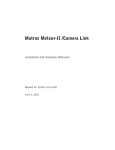
Matrox Meteor-II /Multi-Channel
Matrox Meteor-II /Multi-Channel is a monochrome and
component RGB analog frame grabber for standard and
non-standard video acquisition. Matrox Meteor-II
/Multi-Channel is available in a PCI or PC/104-Plus form factor,
both of which can use a Matrox Meteor-II MJPEG module for
compression and decompression of monochrome and color
images.
12
Chapter 1: Introduction
VMChannel (not available
on CompactPCI and
PC/104-Plus)
To DB-44
Connector
for PCI
form factor
VID_IN1_1
VID_IN2_1
2:1
MUX
VID_IN2_2
VID_IN3_1
Black
Lowpass
filters/
Gain
Aux
A/D
A/D
24
LUT
3 256x8-bit
A/D
Sync
separator
24
32
24
MJPEG
Module
Optocoupler
Trigger
Clk input
Clk output
Hsync
Vsync
Trigger
Exposure timer1
Exposure timer2
Black
Black
4:1
MUX
SYNC_IN
White
White
2:1
MUX
VID_IN3_2
To 30-pin
male,
connector
for
PC/104-Plus
form factor
White
2:1
MUX
VID_IN1_2
TTL*
Drivers
&
Receivers
{
PSG
(optional)
VIA
64
2
2
RX
TX
/RTS
/CTS
SGRAM
RS-232
Drivers
and
Receivers
(4 Mbytes)
UART
32
Not available on PC/104-Plus
form factor
* RS-422 version of these signals are available on the optional RS-422 connector.
This connector is only available on Matrox Meteor-II /Multi-Channel in a PCI form factor.
Acquisition features
Host 32-bit PCI bus
Matrox Meteor-II /Multi-Channel can acquire different types of
standard and non-standard monochrome and component RGB
video. The board features six software-selectable input
channels on which two component RGB or six monochrome
cameras can be attached. Matrox Meteor-II /Multi-Channel
supports acquisition from one camera at a time or simultaneous
acquisition from up to three gen-locked RS-170/CCIR cameras.
Matrox Meteor-II /Multi-Channel supports both single and
Matrox Meteor-II boards
13
dual-tap configurations. It also accepts an external trigger, and
can operate in either asynchronous reset mode or next valid
frame/field mode.
The PCI form factor also includes an auxiliary power supply
input, which can be used to draw auxiliary power from your
computer to provide power to your camera.
Matrox Meteor-II /Digital
Matrox Meteor-II /Digital is a digital frame grabber for
standard and non-standard video acquisition. This board is
only available in a PCI form factor.
VMChannel
Data
100-Pin
Connector
Clk input
Clk output
Hsync input
Hsync output
Vsync input
Vsync output
Valid frames/line
Trigger
Exposure timer1
Exposure timer2
Aux 1 input
Aux 2 input
Aux 1 output
Aux 2 output
Exposure timer1
Exposure timer2
Camera CTRL1
Camera CTRL2
Camera CTRL3
32
RS-422/
LVDS*
Receiver
32
LUT
4 256x8-bit
or
2 4Kx16-bit
32
32
RS-422/
LVDS*
Drivers
&
Receivers
TTL
Buffers
PSG
VIA
64
Trigger
9-Pin Female
Trigger
Connector
Trigger
RX
TX
9-Pin Male
RS-232
Connector
/RTS
/CTS
Optocoupler
32
RS-232
Drivers
and
Receivers
SGRAM
(4 MB)
UART
On separate bracket
* Matrox Meteor-II is available with either RS-422 or LVDS support.
Host 32-bit PCI bus
14
Chapter 1: Introduction
Acquisition features
Matrox Meteor-II /Digital can acquire digital video from
standard and non-standard cameras using the RS-422 or LVDS
differential signed format. It supports image acquisition from
genlocked cameras in 4 x 8-bit, 2 x 16-bit, or 1 x 32-bit
configurations; therefore, up to four cameras can be attached
to acquire four 8-bit or component RGB images. The board also
supports multi-tap grabs (up to four taps). In addition, Matrox
Meteor-II /Digital accepts an external trigger, and can operate
in either asynchronous reset mode or next valid frame/field
mode.
Matrox Meteor-II /1394
Matrox Meteor-II /1394 is an IEEE 1394-to-PCI adapter board
that permits simplified, high-performance digital video capture
using a computer. This board is only available in a PCI form
factor.
6-pin IEEE-1394
Connector
Input
6-pin IEEE-1394
Connector
Input
6-pin IEEE-1394
Connector
Input
Physical
Layer
3.3V regulator
Link
Layer
32
Optional isolation
barrier
12V
input
Host 32-bit PCI bus
Acquisition features
Matrox Meteor-II /1394 supports the transfer of monochrome
or color digital video from cameras which are compliant with
the IEEE 1394 Digital Camera Specification (DCS). Note,
Matrox Meteor-II /1394 has three input ports which can be used
for image acquisition.
Matrox Meteor-II boards
15
The Meteor-II /1394 can also supply power from your computer
through the IEEE 1394 interface.
Matrox Meteor-II MJPEG module
Matrox Meteor-II MJPEG module is an optional board which
module supports lossy and lossless MJPEG (interlaced and
non-interlaced) compression and decompression of color and
monochrome video. There are two versions of the Matrox
Meteor-II MJPEG module: one is for use with the PCI and
CompactPCI form factors, and the other is for use with the
PC/104-Plus form factor. The Matrox Meteor-II MJPEG module
is not supported by Matrox Meteor-II /Digital and /1394.
Pixel Data
Input/Output
Meteor-II
Grab Port
Interface
Color Space
Converter
SRAM
(64Kbytes)
16
Strip Buffer
Memory
24
Block
Data
Host
Interface
8
24
8
Host
Interface
Pixel
Interface
8
Host
Interface
JPEG
Processor
MJPEG
FPGA
Code
Interface
MJPEG Module
Progressive
Path
8
JPEG
Processor
Interface
Memory
Port
64
VIA SGRAM
Interface Port
16
Chapter 1: Introduction
Data transfer
All versions of the Matrox Meteor-II board allow transfer of live
video to Host memory or off-board display memory. To prevent
loss of data during long bus-access latencies found in heavily
loaded computer systems, the Matrox Meteor-II boards (except
Meteor-II /1394) feature 4 Mbytes of SGRAM for temporary
frame storage. All boards except Matrox Meteor-II /1394 are
also equipped with the Matrox Video Interface ASIC (VIA).
All PCI form factor boards (except the Meteor-II /1394) also
have a VMChannel interface (non-bus controller), which is used
to send data to other VM devices found on other Matrox imaging
boards (for example, Matrox Corona, Matrox Genesis main
board, or Matrox Genesis processor board)1.
Software
You can purchase one or more Matrox Imaging software
products that support the Matrox Meteor-II board. These are
the Matrox Imaging Library (MIL) and its derivatives
(MIL-Lite, ActiveMIL-Lite, and Matrox Inspector). All Matrox
software is supported under Windows; consult your software
manual for supported Windows environments.
MIL
MIL is a development library which provides an extensive list
of commands used to capture, process, analyze, transfer,
display, and archive images. Processing and analysis
operations include: spatial filtering operations, morphological
operations, measurements, blob analysis, optical character
recognition (OCR), pattern matching, matrix/bar code reading,
and calibration.
MIL-Lite
MIL-Lite is a subset of MIL. It includes all the MIL commands
for image acquisition, transfer, display control, and archiving.
1. Since the Matrox Meteor-II boards cannot perform the
function of bus controller, they must be connected with at least
one board which is bus controller capable, in order for VMChannel transfers to operate correctly.
Matrox Meteor-II boards
17
ActiveMIL
ActiveMIL is a set of ActiveX controls that are based on MIL.
ActiveMIL was designed for rapid application development
(RAD) tools, such as Microsoft’s Visual Basic. ActiveMIL is
included with MIL. (ActiveMIL-Lite is included with MIL-Lite.)
Inspector
Inspector is an interactive Windows application for image
capture, processing, analysis, and archiving.
MIL Developers can use Matrox Inspector as a prototyping tool
to quickly build proof-of-concept demonstrations for their
machine vision, image analysis, and medical imaging system.
End users can use Matrox Inspector to perform and automate
image enhancement and measurement tasks.
Intellicam
Matrox Intellicam is an interactive Windows program that
allows fast camera interfacing and provides interactive access
to all the acquisition features of your Matrox board. For boards
that accept non-standard video sources, Matrox Intellicam also
has the ability to create custom digitizer configuration format1
(DCF) files, which MIL and its derivatives use to interface to
specific non-standard video sources. Intellicam is included with
both MIL and MIL-Lite.
1. Matrox Meteor-II /Standard and /1394 only support
pre-defined DCF files.
18
Chapter 1: Introduction
What you need to get started
To begin using Matrox Meteor-II, you need the following:
Other useful
considerations
■
computer with a PCI bus and a Pentium processor or better.
■
Windows: See your software package for supported
environments and RAM requirements.
■
A computer with a relatively up-to-date PCI chipset, such as
the Intel 430HX, 430VX, 430TX, 440FX, 440LX, or 440BX for
full Matrox Meteor-II functionality. These chipsets are
recommended because they offer the required
sustained-throughput to Host memory.
■
A computer with an empty full-length 32-bit PCI expansion
slot (bus master capable).
■
A CD drive, and a hard disk or network drive on which to
install the Matrox Meteor-II software.
Inspecting the Matrox Meteor-II package
19
Inspecting the Matrox Meteor-II package
Standard package
When you unpack your Matrox Meteor-II package, you should
check its contents. Note that optional parts might or might not
be included, depending on what you ordered. If something is
missing or damaged, contact your Matrox representative.
If you ordered Matrox Meteor-II, you should receive the
following items:
■
The Matrox Meteor-II /Standard, Matrox Meteor-II
/Multi-Channel, Matrox Meteor-II /Digital, or Matrox
Meteor-II /1394 board.
■
The Matrox Meteor-II Installation and Hardware Reference
manual (this document).
■
A 4-pin power cable, included with Matrox Meteor-II
/Standard and /Multi-Channel (PCI form factor), and with
Matrox Meteor-II /1394.
■
A bracket with flat cables that attach to the trigger and
RS-232 input connectors, included with Matrox Meteor-II
/Digital.
■
A 30-pin connector to interface with the video input
connector, included with Matrox Meteor-II /Standard and
/Multi-Channel for PC/104-Plus (stand-alone version).
Optional items
You might have also ordered one or more of the following:
■
MIL-32/CD, which includes ActiveMIL; MIL-LITE/32 CD,
which includes ActiveMIL-Lite; or Matrox
INSPECTOR-32/CD. MIL and MIL-Lite CDs include
Intellicam.
■
Matrox Meteor-II MJPEG module.
20
Chapter 1: Introduction
■
DBHD44-TO-13BNC input cable with a high density 44-pin
connector and thirteen BNC connectors for the Matrox
Meteor-II /Standard (PCI and CompactPCI form factors). Six
BNC-TO-SVHS (Y/C) adapter cables are shipped with the
DBHD44-TO-13BNC cable.
■
DH44-TO-13BNC/O input cable with a high density 44-pin
connector, available for the Matrox Meteor-II /Standard. This
cable is required if you want to connect to special input and
output signals, such as synchronization signals, control
signals, and DC power output.
■
DBHD44-TO-8BNC input cable with a high density 44-pin
connector and eight BNC connectors for Meteor-II
/Multi-Channel (PCI form factor). Three BNC-TO-SVHS
(Y/C) adapter cables are shipped with the
DBHD44-TO-8BNC cable.
■
DH44-TO-8BNC/O input cable with a high density 44-pin
connector, available for the Matrox Meteor-II
/Multi-Channel. This cable is required if you want to connect
to special input and output signals, such as synchronization
signals, control signals, and DC power output.
■
DBHD100-TO-OPEN cable for the 100-pin digital input
connector on the Matrox Meteor-II /Digital board.
❖ Cables for Matrox Meteor-II /1394 are typically supplied with
the camera.
Handling components
The electronic circuits in your computer and the circuits on
Matrox Meteor-II are sensitive to static electricity and surges.
Improper handling can seriously damage the circuits. Be sure
to follow these precautions:
▲ Caution
■
Drain static electricity from your body by touching a metal
fixture (or ground) before you touch any electronic
component.
■
Avoid letting your clothing come in contact with the circuit
boards or components.
Before you add or remove devices from your computer, always
turn off the power to your computer and all peripherals.
Installation overview
21
Installation overview
The installation procedure consists of the following steps:
1. Complete the hardware installation as described in
Chapter 2. If you have any problems, refer to Appendix A.
2. Complete the software installation as described in
Chapter 3.
More information
For information on using multiple Matrox Meteor-II boards,
refer to Chapter 4, and for in-depth hardware information, refer
to Chapter 5.
If you want technical information about Matrox Meteor-II,
including specifications and connector descriptions, and
pinouts, see Appendix B for Matrox Meteor-II /Standard,
Appendix C for Matrox Meteor-II /Multi-Channel, Appendix D
for Matrox Meteor-II /Digital, and Appendix E for Matrox
Meteor-II /1394.
A history of the development of Matrox Meteor-II is available
in Appendix F.
Conventions
When the term Matrox Meteor-II boards is used, it refers to all
versions of the board.
When the term Meteor-II for PC/104-Plus is used, it refers to
the stand-alone version (MET2+/4 or MET2-MC+/4). Another
version of Matrox Meteor-II is available pre-installed with
Matrox 4Sight, and technical information for this board is
available in the Matrox 4Sight User Guide.
When the term Host is used in this manual, it refers to your
computer.
This manual occasionally makes reference to a MIL-Lite
command. However, anything that can be accomplished with
MIL-Lite can also be accomplished with MIL, ActiveMIL,
ActiveMIL-Lite, or Matrox Inspector.1
1. Most items can be accomplished with Matrox Inspector.
22
Chapter 1: Introduction
Need help?
Appendix A offers solutions to potential problems. If your
Matrox Meteor-II installation questions are not answered in
this manual, contact your local Matrox representative, Matrox
Sales Office, or Matrox Imaging Customer Support Group (see
the Customer Support section at the back of this manual for
telephone numbers).
In the unlikely event of a failure, the warranty and Product
Assistance Request Form at the back of this manual outlines
return conditions and procedures.
Chapter 2: Hardware
installation
This chapter explains how to install the Matrox Meteor-II
hardware.
24
Chapter 2: Hardware installation
Installing Matrox Meteor-II
Before you install your board, some precautionary measures
must be taken. Turn off power to the computer and its
peripherals, and drain static electricity from your body (by
touching a metal part of the computer chassis). Next, follow the
steps to install your board according to its form factor: PCI,
CompactPCI, or PC/104-Plus.
❖ If you are not using Windows NT as your operating system,
your board must be installed before you install the software
(either MIL or one of its derivatives). If you are adding
another Matrox Meteor-II to your computer, you will have to
re-install your software after installing your board.
Installing Matrox Meteor-II for PCI
Use the following steps to install your Matrox Meteor-II board
for PCI:
1. Remove the cover from your computer using the
instructions from your computer manual.
2. Check that you have an empty PCI (32-bit) slot that can
accommodate the board. If you do not have an empty slot,
remove a PCI board from your computer to make room for
your Matrox Meteor-II board and take note of the slot
number you choose.
Connectors of PCI slots
or
Connectors of ISA slots
Installing Matrox Meteor-II
▲ Caution
25
Some computers have a large, black-ridged heat sink that
prevents boards from using most PCI board slots. Your
Matrox Meteor-II must not touch this heat sink. Therefore,
choose a slot where the board completely avoids it.
3. Connect the Matrox Meteor-II MJPEG module to the board
if required. See the section, Installing the Matrox Meteor-II
MJPEG module.
4. If present, remove the blank metal plate located at the back
of the selected slot. Keep the removed screw; you will need
it to fasten the Matrox Meteor-II board.
5. Carefully position Matrox Meteor-II in the selected PCI slot
as illustrated below. If you are using a tower computer,
orient the board to suit the board slots in your computer.
SCREW
METAL
PLATE
MATROX M
ETEOR-II
PCI form factor
32-BIT PCI BOARD SLOT
6. Once perfectly aligned with an empty slot, press the board
firmly but carefully into the connector.
7. Anchor the board by replacing the screw that you removed.
8. If you are installing the Matrox Meteor-II /Standard,
/Multi-Channel, or Meteor-II /1394, proceed to Step 9. If you
are installing the Matrox Meteor-II /Digital board, continue
with the following steps:
26
Chapter 2: Hardware installation
■
If present, remove the blank metal plate located at the
back of a slot next to the Matrox Meteor-II /Digital board;
do not discard this screw.
■
Install the bracket with the trigger and RS-232 input
connectors and fasten it with the screw you just removed.
■
Connect the cables to the 4-pin trigger connector and the
10-pin RS-232 connector on the Matrox Meteor-II /Digital
board (see figure below).
9. Replace the cover of your computer.
10. Connect your video sources. For details, see the Connecting
external devices section.
11. Turn on your computer.
Under Windows 98, when you boot your computer,
Windows’ Plug-and-Play system will detect a new PCI card
and you will be asked to assign a driver to it. At this point,
you should click on Cancel because the driver will be
installed during the installation of MIL or one of its
derivatives.
Installing Matrox Meteor-II
27
Installing Matrox Meteor-II for CompactPCI
Use the following steps to install your Matrox Meteor-II board
for CompactPCI (3U). Note that a 6U replacement bracket is
available.
1. Remove a plate on the subrack, exposing an empty slot.
2. Connect the Matrox Meteor-II MJPEG module to the board
if required. See the section, Installing the Matrox Meteor-II
MJPEG module.
3. Carefully position Matrox Meteor-II along one of the guide
rails and slide the board towards the connector at the back.
Subrack
CompactPCI
Board
Guide slots
28
Chapter 2: Hardware installation
Back plate
of subrack
CompactPCI
connector
Screw
Guide
Handle
4. Press the board firmly but carefully into the connector.
5. When the board is in place, the handle opens automatically,
exposing a screw. Tighten both this screw, and the one at
the top of the bracket.
6. Connect your video sources. For details, see the Connecting
external devices section.
7. Turn on your computer.
Under Windows 98, when you boot your computer,
Windows’ Plug-and-Play system will detect a new PCI card
and you will be asked to assign a driver to it. At this point,
you should click on Cancel because the driver will be
installed during the installation of MIL or one of its
derivatives.
Installing Matrox Meteor-II
29
Installing Matrox Meteor-II for PC/104-Plus
Use the following steps to install your Matrox Meteor-II board
for PC/104-Plus:
1. Matrox Meteor-II for PC/104-Plus can operate in either a
5V or 3.3V system. In some cases, a hole in the PC/104-Plus
(PCI) connector is filled, which prevents another
PC/104-Plus module from being stacked on top. To install
Matrox Meteor-II for PC/104-Plus in a system with a
specific signalling environment, a pin must be removed.
The table and diagram below indicate which pins to cut, and
their locations on the connector.
Signalling
Pin to remove
environment on J3 connector
Remove pin D30
in a 3.3 V system
5V
A1
3.3V
D30
J3
30
32
J1
J2
19
PC/104
(ISA)
PC/104-Plus
(PCI)
CD
PC/104-Plus
expansion site
1
DCBA
Remove pin A1
in a 5 V system
1
0
BA
Top view
2. Connect the Matrox Meteor-II MJPEG module to the board
if required. See the section, Installing the Matrox Meteor-II
MJPEG module.
30
Chapter 2: Hardware installation
3. Check that you have an available PC/104-Plus connector on
the motherboard, or verify that your existing stack can
support another board.
4. If you have existing PC/104 boards in your computer,
remove them and stack them on the PC/104-Plus board.
PC/104 boards must be stacked last.
5. Remove the anchoring screws from the stack; do not discard
them since you will need them to fasten the Matrox
Meteor-II board.
6. Carefully position Matrox Meteor-II over the connectors
and press the board firmly into place.
7. Replace the anchoring screws.
8. Set the rotary switch (next to the PC/104 (ISA) connector)
to 0 if installing the first stackable module, or another
appropriate setting if not the first. See the section, Multiple
board installation, in Chapter 4.
PC/104-Plus
(PCI) connector
Expansion
module
connectors
PC/104
(ISA)connector
Rotary
switch
Motherboard
Video input
connector
9. Connect your video sources. For details, see the Connecting
external devices section.
Installing the Matrox Meteor-II MJPEG module
31
10. Turn on your computer.
Under Windows 98, when you boot your computer,
Windows’ Plug-and-Play system will detect a new PCI card
and you will be asked to assign a driver to it. At this point,
you should click on Cancel because the driver will be
installed during the installation of MIL or one of its
derivatives.
Installing the Matrox Meteor-II MJPEG
module
Matrox Meteor-II MJPEG module is available in two form
factors: one for use with PCI and CompactPCI form factors, and
one for use with the PC/104-Plus form factor. The module is
supported on Matrox Meteor-II /Standard and /Multi-Channel.
PCI and CompactPCI
form factors
1. Position the boards such that the male connector on the
module is aligned with the female connector on the base
board and the female connector on the module is aligned
with the male connector of the base board.
MJPEG module
Meteor-II board
PCI connector
32
Chapter 2: Hardware installation
2. Once the boards are perfectly aligned, press the module
firmly but carefully into the connectors.
PC/104-Plus form factor
On the PC/104-Plus form factor, the expansion connectors are
located on the soldered side of the board. Follow the steps below
to connect the Matrox Meteor-II MJPEG module to Matrox
Meteor-II for PC/104-Plus1:
Top pin
MJPEG
module
MJPEG
connector (male)
Top pin, spacer
and rivet at opposite side
of board
Rivet
Spacer
Meteor-II
PC/104-Plus
Component
side
PC/104-Plus
(PCI)
connector
Expansion module
connector (female)
PC/104
(ISA)
connector
1. Align the connectors of the Matrox Meteor-II MJPEG
module with the expansion module connectors on the
Matrox Meteor-II board.
2. Position the spacer between the boards over each small
hole, next to the MJPEG connectors.
3. Insert the rivet into each hole from the soldered side of the
Matrox Meteor-II MJPEG module, ensuring that it goes
through the spacer.
4. Press the boards together, so the connectors are snapped in
place.
5. Insert the top pin through the hole from the soldered side
of the Matrox Meteor-II MJPEG module to hold the rivet,
spacer, and boards in place.
1. The Matrox Meteor-II MJPEG module 896-00 rev. A has two
connectors and two pins. 896-01 rev. A has three connectors and
five pins.
Connecting external devices
33
Connecting external devices
All boards and form factors have their own particularities
regarding connectors and input devices. In this section, the
boards will be discussed in the following order:
■
Matrox Meteor-II /Standard for PCI.
■
Matrox Meteor-II /Standard for CompactPCI.
■
Matrox Meteor-II /Multi-Channel for PCI.
■
Matrox Meteor-II /Standard and /Multi-Channel for
PC/104-Plus.
■
Matrox Meteor-II /Digital.
■
Matrox Meteor-II /1394.
Matrox Meteor-II /Standard for PCI
Matrox Meteor-II /Standard has six connectors, which are
indicated in the diagram below. Two of these connectors are
located on its bracket.The first four connectors listed are
discussed in detail in Appendix B.
■
Video input connector. Used to receive analog video, as
well as send and receive synchronization signals and power.
■
BNC connector. Used to receive composite analog video.
■
Auxiliary power supply input. Used to route power from
your computer through the Matrox Meteor-II board to your
camera.
■
VMChannel connector. Used to send data to another
Matrox board.
■
Expansion module interface1. Used to connect to the
optional Matrox Meteor-II MJPEG module (for image
compression and decompression).
1. Matrox Meteor-II /Standard boards 750-00 rev. A and 750-01
rev. A do not support the Matrox Meteor-II MJPEG module and
therefore do not have these connectors.
34
Chapter 2: Hardware installation
VMChannel
Auxiliary power supply
input
Video input
BNC
Connector 1 (male) for
expansion module
Connector 2 (female) for
expansion module
Connecting a video input to Meteor-II /Standard for PCI
or CompactPCI
You can connect video sources to Matrox Meteor-II /Standard’s
video input connector, using the optional DBHD44-TO-13BNC
cable. This cable has thirteen BNC connectors and a 44-pin
high-density D-Subminiature plug. The wires of the cable are
color-coded as follows. Connect your cameras accordingly.
Wires
Signals
Expected Input
Form factor
RED (1)
VID_IN1
Analog Video Input1 or Y1
PCI, CompactPCI
GREEN (2)
VID_IN2
Analog Video Input2 or C1
PCI, CompactPCI
BLUE (3)
VID_IN3
Analog Video Input3 or Y2
PCI, CompactPCI
BLACK (4)
VID_IN4
Analog Video Input4 or C2
PCI, CompactPCI
WHITE (5)
VID_IN5
Analog Video Input5 or C4
PCI, CompactPCI
YELLOW (6)
VID_IN6
Analog Video Input6 or Y3
PCI, CompactPCI
PURPLE (7)
VID_IN7
Analog Video Input7 or C3
PCI, CompactPCI
Connecting external devices
Wires
Signals
Expected Input
Form factor
BROWN (8)
VID_IN8
Analog Video Input8 or Y4
PCI
LIGHT BLUE (9)
VID_IN9
Analog Video Input9 or Y5
PCI
ORANGE (10)
VID_IN10
Analog Video Input10 or C5
PCI
PINK (11)
VID_IN11
Analog Video Input11or Y6
PCI
Analog Video Input12 or C6
PCI
LIGHT GREEN (12) VID_IN12
GRAY (13)
OPTOTRIG External trigger input*
35
PCI, CompactPCI
*OPTOTRIG- is usually connected to the ground of the trigger
source.
Connect the supplied BNC-TO SVHS adaptor cables to the
DBHD44-TO-13BNC cable for Y/C input. The PCI form factor
supports up to six Y/C sources, and the CompactPCI form factor
supports up to three. The cable is color coded as follows:
Wires on
Wires on DBHD44-TO-13BNC
Description
BNC-TO-SVHS
BLUE (Y)
Red
(1)
Blue
(3)
Yellow
(6)
Brown
(8)
Light Blue Pink
(9)
(11)
GREEN (C)
Green
(2)
Black
(4)
Purple
(7)
White
(5)
Orange
(10)
Luminance
Light Green Chrominance
(12)
Connecting Matrox Meteor-II /Standard to other
boards
The VMChannel interface allows the transfer of data to other
Matrox boards. Insert a VMChannel backplane (available with
interconnect kits) across the VMChannel interface to connect
the boards. Note that when connecting multiple Matrox boards,
at least one of the boards must be bus-controller capable.
Matrox Meteor-II is not bus-master capable.
36
Chapter 2: Hardware installation
Connecting Matrox Meteor-II /Standard to the auxiliary
power supply input
To use Matrox Meteor-II /Standard to power your camera:
1. Use the 4-pin power cable to connect the auxiliary power
supply connector to the power supply in the computer.
2. Ensure that the jumper is across the appropriate Matrox
Meteor-II auxiliary power supply selection pins, for the
required voltage (5 V or 12 V). See Appendix B for a
diagram.
3. Use the DBHD44-TO-13BNC/O cable to connect your
camera’s video output and power supply input to the video
input connector. Note that the total current drawn by all
the cameras is limited to 1.5 A, and the circuit uses an
auto-resettable fuse.
Matrox Meteor-II /Standard for CompactPCI
Matrox Meteor-II for CompactPCI has five connectors, which
are indicated in the diagram below. Two of these connectors are
located on its bracket, and are discussed in detail in Appendix
B.
■
Video input connector. Used to receive analog video, as
well as send and receive synchronization signals and power.
■
BNC connector. Used to receive composite analog video.
■
CompactPCI connector. Used to connect your board to the
PCI bus.
Connecting external devices
■
37
Expansion module interface. Used to connect to the
optional Matrox Meteor-II MJPEG module (for image
compression and decompression).
Connector 2 (female) for
expansion module
CompactPCI connector
Video input
BNC
Connector 1 (male) for
expansion module
Connecting a video input (CompactPCI)
You can connect video sources to Matrox Meteor-II /Standard’s
video input connector CompactPCI form factor, using the
optional DBHD44-TO-13BNC cable. See the section,
Connecting a video input to Meteor-II /Standard for PCI or
CompactPCI.
Matrox Meteor-II /Multi-Channel for PCI
Matrox Meteor-II /Multi-Channel has six connectors, which are
indicated in the diagram below. One of these connectors is
located on its bracket. The first four connectors listed are
discussed in detail in Appendix C.
■
Video input connector. Used to receive analog video, as
well as send and receive synchronization signals and power.
■
VMChannel connector. Used to send data to another
Matrox board.
38
Chapter 2: Hardware installation
■
Auxiliary power supply input. Used to route power from
your computer through the Matrox Meteor-II board to your
camera.
■
Expansion module interface. Used to connect the optional
Matrox Meteor-II MJPEG module (for image compression
and decompression).
VMChannel
Auxiliary power supply input
Connector 1 (male) for
expansion module
Video input
Connector 2 (female) for
expansion module
Connecting a video input to Meteor-II /Multi-Channel
Connect video sources to Matrox Meteor-II /Multi-Channel’s
video input connector, using the optional DBHD44-TO-8BNC
cable. This cable has eight BNC connectors and a 44-pin
high-density D-Subminiature plug. The wires of the cable are
color-coded as follows:
Wires
Signals
Description
RED (1)
VID1_IN1
Analog Video Input1, R
GREEN (2)
VID1_IN2
Analog Video Input2, G
BLUE (3)
VID1_IN3
Analog Video Input3, B
BLACK (4)
SYNC_IN
SYNC input
GREY (5)
OPTOTRIG*
External trigger input
WHITE (6)
VID2_IN1
Analog Video Input4, R
YELLOW (7)
VID2_IN2
Analog Video Input5, G
PURPLE (8)
VID2_IN3
Analog Video input6, B
Connecting external devices
39
*OPTOTRIG- is usually connected to the ground of the trigger
source.
Connecting Matrox Meteor-II /Multi-Channel to other
boards
The VMChannel interface allows the transfer of data to other
Matrox boards. Insert a VMChannel backplane (available with
interconnect kits) across the VMChannel interface to connect
the boards. Note that when connecting multiple Matrox boards,
at least one of the boards you are connecting must be
bus-controller capable. Matrox Meteor-II is not bus-controller
capable.
Connecting Matrox Meteor-II /Multi-Channel to the
auxiliary power supply input
To use Matrox Meteor-II /Multi-Channel to power your camera:
1. Use the 4-pin power cable to connect the auxiliary power
supply connector to the power supply in the computer.
2. Ensure that the jumper is across the appropriate Matrox
Meteor-II auxiliary power supply selection pins, for the
required voltage (5 V or 12 V). See Appendix B for a
diagram.
3. Use the DBHD44-TO-8BNC/O cable to connect your
camera’s video output and power supply input to the video
input connector. Note that the total current drawn by all
the cameras is limited to 1.5 A, and the circuit uses an
auto-resettable fuse.
Matrox Meteor-II /Standard and /Multi-Channel
for PC/104-Plus
Matrox Meteor-II /Standard and /Multi-Channel PC/104-Plus
form factor have seven connectors, which are indicated in the
diagram below.
■
Video input connector. A connector used to receive analog
video, as well as send and receive synchronization signals
and power.
■
PC/104-Plus (PCI) connector. An interface connector to
send data across the PCI bus.
40
Chapter 2: Hardware installation
■
PC/104 (ISA) connectors. Two interface connectors to send
data across the ISA bus.
■
Expansion module interface. Three connectors used to
attach to the optional Matrox Meteor-II MJPEG module (for
image compression and decompression); located on the
soldered side of the board.
PC/104-Plus
(PCI)
Expansion
module
connectors
PC/104
(ISA)
Video input
connector
Connecting a video input to Matrox Meteor-II for
PC/104-Plus
Connect video sources to Matrox Meteor-II /Standard or
/Multi-Channel through their video input connector, a 30-pin
right-angle male connector. A standard cable for PC/104-Plus
form factor boards is not available from Matrox. You can use
the included mating connector, crimp the ribbon cable to it and
attach your required connector to the other end of the ribbon
cable. Then, connect this custom cable to the video input
connector. See Appendices B and C for the pinouts, signals, and
ribbon cable information for the /Standard and /Multi-Channel,
respectively.
Matrox Meteor-II /Digital
Matrox Meteor-II /Digital has four connectors, which are
indicated in the diagram below. Only one of these connectors is
located on its bracket. All these connectors listed below are
discussed in detail in Appendix D.
Connecting external devices
41
■
Digital Video input. Used to receive digital video, as well
as send and receive synchronization signals.
■
Trigger input. A connector for direct trigger input in TTL
or opto-isolated format.
■
RS-232 input connector. Used as a standard RS-232 serial
port interface.
■
VMChannel. Used to send data to another Matrox board.
VMChannel
RS-232
Trigger input
Video input
Connecting a video input to Meteor-II /Digital
Connect video sources to Matrox Meteor-II /Digital’s video
input connector, using the optional DBHD100-TO-OPEN. This
cable can be customized to fit with the connector on your video
source. See Appendix D for the pinouts, signals, and mating
connector supplier.
Connecting Matrox Meteor-II /Digital to other boards
The VMChannel interface allows the transfer of data to other
Matrox boards. Insert a VMChannel backplane (available with
interconnect kits) across the VMChannel interface to connect
the boards. Note that when connecting multiple Matrox boards,
at least one of the boards you are connecting must be
bus-controller capable. Matrox Meteor-II is not bus-controller
capable.
42
Chapter 2: Hardware installation
Matrox Meteor-II /1394
Matrox Meteor-II /1394 has four connectors, which are
indicated in the diagram below. Three of these connectors are
located on its bracket, and are discussed in detail in Appendix
E.
Auxiliary power
supply input
1394
ports
PCI connector
■
1394 ports. Used to provide bi-directional serial
communication and power. Each I/O port features a standard
6 pin connector. See Appendix E for pinouts.
■
Auxiliary power supply input. Used to route power from
your computer through the Matrox Meteor-II /1394 board to
your camera.
Connecting a device to Meteor-II /1394
Connect devices to Matrox Meteor-II /1394’s ports, using the
6-pin connectors. The cable for the Meteor-II /1394 is not
available from Matrox, but 1394 devices, such as cameras,
typically include a cable. See Appendix E for the pinouts,
signals, and mating connector supplier.
Connecting external devices
43
Connecting Matrox Meteor-II /1394 to the auxiliary
power supply input
To use Matrox Meteor-II /1394 to power your device:
1. Use the 4-pin power cable to connect the auxiliary power
supply connector to the power supply in the computer.
2. Connect your camera’s 1394 cable to one of the board’s ports.
Note that the total current drawn by all the cameras is
limited to 1.5 A.
44
Chapter 2: Hardware installation
Chapter 3: Installing software
This chapter explains how to install the Matrox Meteor-II
software.
46
Chapter 3: Installing software
Installing the software
To install any Matrox imaging software, place its CD in the
appropriate drive; the setup.exe file will run automatically.
While installing the software, you will be asked to provide the
following information:
■
The drive and directory in which to install the software.
■
The target operating system and compiler.
■
The type of Matrox hardware that is installed in your
computer.
❖ If you have an MGA board, check the MGA control panel to
ensure that you have the latest display driver installed. If
you do not have the latest, install the display driver that is
on the CD.
After installation, read the readme file(s) recommended by the
installation program.
Note about Matrox Intellicam
MIL-Lite uses digitizer configuration formats (DCFs) to
configure the camera interface on Matrox digitizers. The DCF
defines, among other things, the video timing signals and the
video data format. Matrox Intellicam can be used to create or
customize a DCF file, if the supplied files do not include one
that matches your video source. Note that Matrox Meteor-II
/Standard and /1394 only accept standard input formats;
therefore, you can only use the predefined DCFs.
For more information about Matrox Intellicam, refer to the
Matrox Intellicam User Guide.
Chapter 4: Using multiple
Matrox Meteor-II boards
This chapter explains how to use multiple Matrox Meteor-II
boards.
48
Chapter 4: Using multiple Matrox Meteor-II boards
Using multiple Matrox Meteor-II boards
This section describes how to use multiple Matrox Meteor-II
boards. When a grab buffer is selected for display, grabbed
images are displayed on the VGA, live or pseudo-live,
depending on the operating computer and the position of the
windows. Note that the PCI bandwidth is limited, and heavy
usage can affect the data transfer in computers using multiple
boards.
Multiple board installation
Installing multiple PCI
and CompactPCI
cards
Install each additional Matrox Meteor-II board, PCI and
CompactPCI form factors, as you installed the first board (refer
to Chapter 2). In other words, place each additional board in an
empty slot. For the PCI form factor, ensure that the installed
boards avoid the CPU heat sink.
Theoretically, you can have as many as 16 Matrox Meteor-II
PCI/CompactPCI boards installed in your computer at one
time; this number is, however, limited by the number of empty
slots in your computer and, for simultaneous grabs, by the
available bandwidth of your computer (discussed later in this
chapter).
Using MIL-Lite, you have to allocate a MIL system for each
board and allocate the resources of each MIL system.
Multiple board installation
Installing multiple
PC/104-Plus modules
49
You can stack a maximum of four PC/104-Plus modules, shown
in the diagram below. Note that if you have PC/104 modules in
your computer, they must be placed at the top of the stack.
Top screw
ISA connectors
PCI connector
Host board
In addition, you must set the rotary switch of each PC/104-Plus
module to a unique setting in the stack. Setting the rotary
switch dedicates a group of PCI signals to the module in the
stack: clock, request grant, ID select, and interrupt signals. It
is recommended that the first module installed (the module
closest to the Host CPU board) be configured to 0, the second
1, and so on. The table below shows the recommended switch
setting for each module, as well as the dedicated signals.
Switch Module Interrupt Request
ID
position position
select
grant
0 or 4
1
Interrupt A
0
0
1 or 5
2
Interrupt B
1
1
2 or 6
3
Interrupt C
2
2
3 or 7
4
Interrupt D
2
3
50
Chapter 4: Using multiple Matrox Meteor-II boards
If you are installing an additional Matrox Meteor-II board on
Matrox 4Sight, the module already installed has the setting
fixed at 0; therefore, the setting of the additional module must
be at a setting other than 0 or 4.
Grabbing simultaneously from different
boards
You can simultaneously grab images from cameras attached to
different Matrox Meteor-II boards. To grab at exactly the same
time, the cameras must be genlocked (synchronized) and their
corresponding digitizer configuration formats must be the
same. Note that this restriction does not apply to Matrox
Meteor-II /1394
The number of cameras from which you can simultaneously
grab is determined by the PCI bandwidth available in your
computer.
.
Matrox Meteor-II
Matrox Meteor-II
Grabbing from two genlocked cameras
Grabbing simultaneously from different boards
PCI bandwidth
requirements
51
Matrox Meteor-II /Standard, /Multi-Channel, and /Digital have
a low susceptibility to PCI bus latency due to 4 Mbytes of
SGRAM. In addition, sustained PCI-transfers to memory
require the use of a high performance PCI core-logic chipset,
such as the Intel 440LX or 440BX. If a high performance chipset
is used with a Matrox Meteor-II /Standard or /Multi-Channel
board, you should not have any PCI bandwidth problems when
grabbing up to two full-sized color images simultaneously
(using two boards). However, grabbing more than two images
simultaneously might result in PCI bandwidth problems.
As a reference point, grabbing one full-sized NTSC or PAL
image in real time will require a PCI bandwidth of 35
Mbytes/sec or 42 Mbytes/sec, respectively, when transferring in
RGBX (32-bit) mode.
With the Matrox Meteor-II /Digital board, you can experience
PCI bandwidth problems when grabbing from multiple
cameras that require a high bandwidth.
When grabbing from three or more Matrox Meteor-II boards
simultaneously, you will have to reduce the image size to avoid
reaching the upper limits of the overall available bandwidth.
Matrox Meteor-II /1394
Although Matrox Meteor-II /1394 supports simultaneous input
from multiple cameras, there are issues with respect to both
the PCI bus and the IEEE 1394 bus that restricts the actual
number. With respect to the PCI bus, the available sustained
bandwidth is a factor, like other Matrox Meteor-II boards.
However, Matrox Meteor-II /1394 has a much smaller FIFO,
and is therefore more susceptible to long PCI bus latencies.
With respect to the IEEE 1394 bus, Matrox Meteor-II /1394
OHCI-Lynx PCI-to-1394 Host controller is compatible with
serial IEEE 1394 bus data rates of 100, 200, or 400 Mbits per
second, and these rates are shared across the three input ports.
Once a time slice is allocated, the device is guaranteed to have
that time slice, and therefore transfer data; however, the time
slices available will pose a limitation. In smaller systems, for
example with two or three cameras, there should be enough
time slices to handle the load.
52
Chapter 4: Using multiple Matrox Meteor-II boards
Chapter 5: Matrox Meteor-II
hardware reference
This chapter explains the architecture of the Matrox
Meteor-II hardware, as well as the available features and
modes.
54
Chapter 5: Matrox Meteor-II hardware reference
Matrox Meteor-II hardware reference
This chapter provides information on the architecture,
operating modes, and supported features of the Matrox
Meteor-II boards.
For a summary of the information given in this chapter and
detailed specifications of connectors and pinouts, refer to
Appendices B, C, D, and E of this manual.
Matrox Meteor-II /Standard grab section
The grab section of the Matrox Meteor-II /Standard board uses
a video decoder to capture composite RS-170, CCIR, NTSC, and
PAL, and component (Y/C) NTSC and PAL.
VMChannel (not available
on CompactPCI and
PC/104-Plus)
BNC Connector for
PCI and Compact
PCI form factors
To DB-44
Connector for
PCI and Compact
PCI form factors
To 30-pin male,
right-angle
connector for
PC/104-Plus
form factor
Not available on
CompactPCI
form factor
VID_IN1
VID_IN2
VID_IN3
VID_IN4
VID_IN5
VID_IN6
VID_IN7
VID_IN8
VID_IN9
VID_IN10
VID_IN11
VID_IN12
Low
Pass
Filter
{
RX
TX
/RTS
/CTS
32
MJPEG
Module
(optional)
Optocoupler
64
2
2
RS-232
drivers &
receivers
Not available on PC/104-Plus
form factor
.
24
12:1
MUX
Trigger
Aux
Gain Decoder
VIA
UART
SGRAM
(4 Mbytes)
32
Host 32-bit PCI bus
Matrox Meteor-II /Standard grab section
Performance
The video timing parameters supported by the Matrox
Meteor-II /Standard board are as follows:
CCIR 601 sampling
rates
Square pixel sampling
rates
NTSC
PAL
NTSC
PAL
Field rate (Hz)
60
50
60
50
Pixel/line (Pixels)
858
864
780
944
Active pixel/line (Pixels)
720
720
640
768
Active lines/frame (Lines)
480
580
480
580
Pixel rate (MHz)
13.5
13.5
12.27
14.75
27
27
24.54
29.50
15.750
15.625
15.750
15.625
ADC sampling rate (MHz)
Line rate (KHz)
55
Input channels
Matrox Meteor-II /Standard for PCI and PC/104-Plus can
switch between up to twelve independent composite or six Y/C
video sources. Matrox Meteor-II /Standard for CompactPCI can
switch between seven independent composite sources, or up to
three Y/C video sources.
You can only acquire data from one channel at a time. Channels
can be selected with the MIL-Lite command, MdigChannel().
Low-pass filter
The input low-pass filtering stage is used to limit high
frequency noise and aliasing effects at the input of the decoder.
The filter used on Matrox Meteor-II /Standard for PCI and
CompactPCI is a 4th order Butterworth filter with a cutoff
frequency of 8 MHZ. The filter used on Matrox Meteor-II
/Standard for PC/104-Plus is a single-order filter with a cutoff
frequency of 6 MHz.
Video decoder
A multi-standard video decoder is used to convert NTSC and
PAL analog video signals that are in composite (CVBS), or (Y/C)
formats to digitized component video. The decoder supports
56
Chapter 5: Matrox Meteor-II hardware reference
RGB 8:8:8 (24-bit), RGB 5:6:5, YUV 4:2:2, and YUV 4:1:1 output
pixel formats. Note that YUV 4:2:2 output pixel formats are
grabbed as YUYV.
The video decoder on all form factors also features automatic
gain control (AGC). However, you can disable this feature
(MIL-Lite MdigControl() with
M_GRAB_AUTOMATIC_INPUT_GAIN set to M_DISABLE) and
adjust the gain manually (MdigControl() with
M_GRAB_INPUT_GAIN).
UART
Matrox Meteor-II /Standard for PCI and CompactPCI feature
a Universal Asynchronous Receiver/Transmitter (UART) that
provides an RS-232 serial interface. For example, this allows
you to remotely control a camera or a motion control unit, or
remotely communicate with a program logic controller (PLC).
The UART is programmed using the MIL-Lite command
MdigControl() with the M_UART... control types.
Trigger
Matrox Meteor-II /Standard accepts an external trigger input
which allows image acquisition to be synchronized to external
events. The trigger is synchronous to the incoming video stream
and it is received through an opto-coupler that helps isolate the
rest of the circuitry from surges. Matrox Meteor-II /Standard
operates in next valid frame/field mode. When in this mode, the
digitizer waits for the next valid frame or field (as specified by
the DCF file) before commencing the grab. This trigger mode
functions in one of three ways:
■
Edge-triggered monoshot acquisition: The VIA (Video
Interface Asic) waits for the rising/falling* edge to capture a
single frame.
■
Edge-triggered continuous acquisition: The VIA waits
for the rising/falling* edge to start a continous grab.
■
Level-sensitive "continuous" acquisition: The VIA grabs
continuously while the level of the trigger is high/low*.
* The polarity of the active and inactive levels of the trigger
signal are software programmable.
Matrox Meteor-II /Standard grab section
57
Trigger signals connected to the OPTOTRIG- and OPTOTRIG+
input pins, pass through an opto-coupler, a device that protects
the board from outside surges; OPTOTRIG- is usually
connected to the ground of the trigger source. The voltage
difference across OPTOTRIG+ and OPTOTRIG- must be
between 4.05 V and 9.16 V for logic high, and between -5.0 V
and 0.8 V for logic low. Refer to Appendix B for the pinouts of
these signals on your respective form factor.
User bits
Matrox Meteor-II /Standard supports four auxiliary user bits
through the video input connector: two input and two output.
These are available for controlling external events such as a
strobe light. User bits are programmed using the MIL-Lite
command MdigControl().
Using the auxiliary power supply
Matrox Meteor-II /Standard can supply power to your camera.
Use the 4-pin power cable provided with your board to connect
to the power supply of your computer. The operating voltage
can be set to either 5 V or 12 V, but the current drawn by all
cameras is limited to 1.5 A. The circuit uses an auto-resettable
fuse. For further information on connecting to the auxiliary
power supply connector, see the section, Connecting Matrox
Meteor-II /Standard to the auxiliary power supply input in
Chapter 2, and Appendix B. Note that this input is not available
on the CompactPCI and PC/104-Plus form factors.
58
Chapter 5: Matrox Meteor-II hardware reference
Matrox Meteor-II /Multi-Channel
grab section
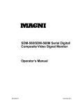
The grab section of the Matrox Meteor-II /Multi-Channel board
captures monochrome or component-RGB video signals from
standard and non-standard cameras. Six monochrome or two
RGB cameras can be attached.
VMChannel (not available
on CompactPCI and
PC/104-Plus)
To DB-44
Connector
for PCI
form factor
VID_IN1_1
VID_IN2_1
2:1
MUX
VID_IN2_2
VID_IN3_1
Black
Lowpass
filters/
Gain
Aux
A/D
A/D
24
LUT
3 256x8-bit
A/D
Sync
separator
24
32
24
MJPEG
Module
Optocoupler
Trigger
Clk input
Clk output
Hsync
Vsync
Trigger
Exposure timer1
Exposure timer2
Black
Black
4:1
MUX
SYNC_IN
White
White
2:1
MUX
VID_IN3_2
To 30-pin
male,
connector
for
PC/104-Plus
form factor
White
2:1
MUX
VID_IN1_2
TTL*
Drivers
&
Receivers
{
PSG
(optional)
VIA
64
2
2
RX
TX
/RTS
/CTS
SGRAM
RS-232
Drivers
and
Receivers
(4 Mbytes)
UART
32
Not available on PC/104-Plus
form factor
* RS-422 version of these signals are available on the optional RS-422 connector.
This connector is only available on Matrox Meteor-II /Multi-Channel in a PCI form factor.
.
Host 32-bit PCI bus
Matrox Meteor-II /Multi-Channel grab section
Performance
59
The video timing parameters (including those for progressive
scan) supported by the Matrox Meteor-II /Multi-Channel board
are as follows:
Max
Number of pixels / line (including sync and blanking) 4096*
Number of lines / frame (including sync and blanking) 4096*
Sampling rate (with external clock input, or in
line-locking mode)
30 MSPS
Note that the maximum number of pixels per line that MIL
supports is:
Pixels
-------------- x Number of Lines ≤ 4 Mbytes
Line
Input channels
The Matrox Meteor-II /Multi-Channel has six independent
analog channels. These channels can support input from two
RGB or six monochrome cameras where the channels can be
selected with the MIL-Lite MdigChannel() command.
Low-pass filter
The input low-pass filtering stage is used to limit high
frequency noise and aliasing effects at the input of the triple
A/D converter. The filter used on Matrox Meteor-II
/Multi-Channel is a 4th order Butterworth filter with a cutoff
frequency of 10 MHz.
Gain
Matrox Meteor-II /Multi-Channel has adjustable gains. This
allows you to optimize the video input signal range.
60
Chapter 5: Matrox Meteor-II hardware reference
You can change the gain value using the MIL-Lite
MdigControl() command. The supported gain factors are as
follows:
Input video signal
amplitude
(excluding sync)
Total input video Required
signal amplitude gain
(including sync) setting
MIL
0.0 V up to 0.5 V
0.0 - 0.7 Vpp
4
M_GAIN3
0.5 V up to 0.7 V
0.7 - 1.0 Vpp
2.8 (default) M_GAIN2
0.7 V up to 1.0 V
1.0 - 1.4 Vpp
2
M_GAIN1
1.0 V up to 1.5 V
1.4 - 2.1 Vpp
1.3
M_GAIN0
1.5 V up to 2.0 V
2.1 - 2.9 Vpp
1
M_GAIN4
Triple A/D converter
A triple A/D converter with external reference generation and
sync slicing is used for component RGB digitization. The
converter can be operated at up to 30 MSPS.
In addition, the converter’s black and white reference levels can
be adjusted individually. The black and white reference levels
can be adjusted between 0.6 V to 1.6 V and 1.6 V to 2.6 V
respectively, in increments of 10.23 mV (98 distinct
adjustments).
Use the MIL-Lite MdigReference() command to set the black
and white reference levels.
PSG
The Programmable Synchronization Generator (PSG) is
responsible for managing all timing and synchronization
signals.
Phase-locked loop
The high-performance, low-jitter phase-locked loop (PLL) uses
frequency synthesis techniques to generate the clock signal,
when necessary.
The PLL can use the following sources as a reference:
Matrox Meteor-II /Multi-Channel grab section
61
■
The on-board crystal oscillator.
■
The horizontal video synchronization signal supplied by the
video source (line-locked mode).
When in line-locked mode and accepting a composite video
signal, the PLL can synchronize to either serrated or block
vertical synchronization signals.
■
The clock signal supplied by the video source (to generate a
different clock).
When the input source supplies a sampling clock that does not
require adjustment, the PLL is bypassed to avoid adding jitter
to the supplied clock.
General synchronization
Matrox Meteor-II /Multi-Channel can operate in either slave
or master mode.
Slave mode
Master mode
■
In slave mode, the video source provides the synchronization
information to Matrox Meteor-II /Multi-Channel. It can
accept one of the following synchronization schemes:
❐
The video source encodes the synchronization signals on
the analog video signal provided to the board.
❐
The video source supplies the horizontal and/or vertical
synchronization signals separately in TTL format.
❐
The video source provides a composite synchronization
signal in TTL format, separate from the analog video.
■
Synchronization information can be sent either with the
video data, or on a separate analog synchronization channel.
■
In master mode, Matrox Meteor-II /Multi-Channel
generates (using the PSG) the horizontal and/or vertical
(TTL) synchronization signals and supplies them to the video
source. This allows the video source to synchronize to the
board.
62
Chapter 5: Matrox Meteor-II hardware reference
Trigger
Matrox Meteor-II /Multi-Channel accepts an external trigger
input which allows image acquisition to be synchronized to
external events. The board can operate in one of two modes, and
the selected mode is specified by the DCF.
Matrox Meteor-II /Multi-Channel can operate in next valid
frame/field mode When in this mode, the digitizer waits for the
next valid frame or field (as specified by the DCF file) before
commencing the grab. This trigger mode functions in one of
three ways:
■
Edge-triggered monoshot acquisition: The VIA (Video
Interface Asic) waits for the rising/falling* edge to capture a
single frame.
■
Edge-triggered continuous acquisition: The VIA waits
for the rising/falling* edge to start a continous grab.
■
Level-sensitive "continuous" acquisition: The VIA grabs
continuously while the level of the trigger is high/low*.
* The polarity of the active and inactive levels of the trigger
signal are software programmable.
Matrox Meteor-II /Multi-Channel can also operate in
asynchronous reset mode. In this mode, the digitizer resets the
camera to begin a new frame when the trigger signal is received.
Direct TTL trigger
Trigger signals can be received in TTL format directly through
the video-input connector on the PCI form factor. The TTL level
signal must have a maximum amplitude of 5 V. A signal over
2 V is considered high while anything less than 0.8 V is
considered low. The transition of 0.8 V to 2 V is considered to
be the rising edge.
The trigger signal’s pulse width must be greater than one pixel.
You can determine the pulse width by taking the inverse of the
pixel frequency. For example, if the pixel frequency is
12.27 MHz, the minimum pulse width is 1/12.27 MHz ≈ 82
nanoseconds.
Note the PC/104-Plus form factor does not support a TTL
trigger.
Matrox Meteor-II /Multi-Channel grab section
opto-isolated trigger
63
Trigger signals connected to the OPTOTRIG- and OPTOTRIG+
input pins, pass through an opto-coupler, a device that protects
the board from outside surges; OPTOTRIG- is usually
connected to the ground of the trigger source. The voltage
difference across OPTOTRIG+ and OPTOTRIG- must be
between 4.05 V and 9.16 V for logic high, and between -5.0 V
and 0.8 V for logic low. Refer to Appendix C for the pinouts of
these signals on your board.
UART
Matrox Meteor-II /Multi-Channel features a Universal
Asynchronous Receiver/Transmitter (UART) that provides an
RS-232 serial interface. For example, this allows you to
remotely control a camera or a motion control unit, or remotely
communicate with a program logic controller (PLC). The UART
is programmed using the MIL-Lite command MdigControl()
with the M_UART... control types.
Note that the UART is not present on the Meteor-II
/Multi-Channel for PC/104-Plus.
Lookup table (LUT)
Matrox Meteor-II /Multi-Channel has three 256x8-bit input
lookup tables (LUTs), allowing independent re-mapping of
three 8-bit input streams.
The LUTs on the Matrox Meteor-II /Multi-Channel for PCI
support RGB 8:8:8 (24-bit) output pixel formats. The LUTs on
the PC/104-Plus form factor support RGB 8:8:8, RGB 5:6:5, and
RGB 5:5:5 output pixel formats. LUTs are programmed using
the MIL-Lite command, MdigLut().
User bits
Meteor-II /Multi-Channel supports four auxiliary TTL user bits
through the video input connector: two input and two output.
These are available for controlling external events such as a
strobe light or PLC. User bits are programmed using the
MIL-Lite command MdigControl().
64
Chapter 5: Matrox Meteor-II hardware reference
Using the auxiliary power supply
Matrox Meteor-II /Multi-Channel can supply power to your
camera. Use the 4-pin power cable provided with your board to
connect to the power supply of your computer. The operating
voltage can be set to either 5 V or 12 V, but the current drawn
by all cameras is limited to 1.5 A. The circuit uses an
auto-resettable fuse. For further information on connecting to
the auxiliary power supply connector, see the section,
Connecting Matrox Meteor-II /Multi-Channel to the auxiliary
power supply input in Chapter 2, and Appendix B. Note that
this input is not available on the CompactPCI and PC/104-Plus
form factors.
Matrox Meteor-II /Digital grab section
The grab section of the Matrox Meteor-II /Digital board
captures video from standard and non-standard digital
cameras. It supports component RGB, as well as monochrome
acquisition, in single or multi-tap configurations. Up to four
genlocked cameras can be attached to acquire four 8-bit or two
16-bit inputs.
The board is available in two versions to support either the
RS-422 or the LVDS interface, but is available for the PCI form
factor only.
Matrox Meteor-II /Digital grab section
65
VMChannel
32
Data
100-Pin
Connector
Clk input
Clk output
Hsync input
Hsync output
Vsync input
Vsync output
Valid frames/line
Trigger
Exposure timer1
Exposure timer2
Aux 1 input
Aux 2 input
Aux 1 output
Aux 2 output
Exposure timer1
Exposure timer2
Camera CTRL1
Camera CTRL2
Camera CTRL3
RS-422/
LVDS*
Receiver
32
LUT
4 256x8-bit
or
2 4Kx16-bit
32
32
RS-422/
LVDS*
Drivers
&
Receivers
TTL
Buffers
PSG
VIA
64
Trigger
9-Pin Female
Trigger
Connector
Trigger
32
RX
TX
9-Pin Male
RS-232
Connector
Optocoupler
/RTS
/CTS
RS-232
Drivers
and
Receivers
SGRAM
(4 MB)
UART
On separate bracket
* Matrox Meteor-II is available with either RS-422 or LVDS support.
Host 32-bit PCI bus
.
Performance
The video timing parameters supported by the Matrox
Meteor-II /Digital board are as follows:
Max
Number of pixels / line (including sync and blanking)
65536
Number of lines / frame (including sync and blanking)
65536
Sampling rate (LVDS, or LVDS with external clock input)
40 Mhz
Sampling rate (RS-422 or RS-422 with external clock input) 25 Mhz
66
Chapter 5: Matrox Meteor-II hardware reference
UART
Matrox Meteor-II /Digital features a Universal Asynchronous
Receiver/Transmitter (UART) that provides an RS-232 serial
interface. For example, this allows remote camera
configuration, a motion control unit, or of a program logic
controller (PLC). The UART is programmed using the MIL-Lite
function, MdigControl() with the M_UART... control types.
Lookup table (LUT)
The Matrox Meteor-II /Digital board has four 256x8-bit
programmable lookup tables. The LUTs on Matrox Meteor-II
/Digital can be operated as four 8-bit lookup tables, two 10-bit
lookup tables, or two 12-bit lookup tables.
PSG
The Programmable Synchronization Generator (PSG) is
responsible for managing all timing and synchronization
signals.
Control signals
The following is a short description of the control signals on the
Matrox Meteor-II /Digital interface. Note that depending on the
version of your board, the signals will be in RS-422 or LVDS
format. It is indicated when other signals such as TTL signals
are also supported.
Synchronization
The interface can receive and/or supply the HSYNC and
VSYNC signals. The VIA receives the synchronization signals
from the PSG or from an external source.
Valid
The VIA also receives a VALID signal that can either be
generated by the PSG or an external source. When received by
PSG, it can indicate valid pixels on a line by line basis. When
received from an external source, it can indicate valid pixels on
a pixel by pixel basis.
Clock
The interface of the Matrox Meteor-II /Digital board can receive
and supply a clock, simultaneously.
Matrox Meteor-II /Digital grab section
67
Auxiliary
Seven general purpose auxiliary signals are supported: four
RS-422 or LVDS user signals (two input, two output), and three
TTL output signals. These are available for controlling external
devices, such as a strobe light. User signals are programmed
using the MIL-Lite command MdigControl().
Exposure
Two timers in the PSG can generate two exposure signals
simultaneously. There are available in TTL or RS-422/LVDS
formats. Exposures are programmed using the MIL-Lite
function, MdigControl().
Trigger
Three trigger inputs are routed directly to the PSG; the
interface supports TTL and RS-422/LVDS trigger input. In
addition, a trigger signal connected to the OPTOTRIG- and
OPTOTRIG+ input pins, passes through an opto-coupler, a
device that protects the board from outside surges; OPTOTRIGis usually connected to the ground of the trigger source. This
external trigger input allows image acquisition to be
synchronized with external events. The board can operate in
one of two modes, and the selected mode is specified by the DCF.
Matrox Meteor-II /Digital can operate in next valid frame/field
mode When in this mode, the digitizer waits for the next valid
frame or field (as specified by the DCF file) before commencing
the grab. This trigger mode functions in one of three ways:
■
Edge-triggered monoshot acquisition: The VIA (Video
Interface Asic) waits for the rising/falling* edge to capture a
single frame.
■
Edge-triggered continuous acquisition: The VIA waits
for the rising/falling* edge to start a continous grab.
■
Level-sensitive "continuous" acquisition: The VIA grabs
continuously while the level of the trigger is high/low*.
* The polarity of the active and inactive levels of the trigger
signal are software programmable.
Matrox Meteor-II /Digital can also operate in asynchronous
reset mode. In this mode, the digitizer resets the camera to
begin a new frame when the trigger signal is received.
68
Chapter 5: Matrox Meteor-II hardware reference
Matrox Meteor-II /1394
Matrox Meteor-II /1394 is capable of acting as bus manager
(cycle master), isochronous resource manager, and node
controller ("root"). The cycle master triggers the data signal at
125-microsecond intervals. The isochronous resource manager
is responsible for reserving, distributing, and managing the two
modes of data streams (isochronous and asynchronous) along
the available bandwidth. The root controller can control all
peripheral devices connected (up to a maximum of 62).
The 1394 bus transfers real-time (isochronous) data streams
through a four-layered architecture, two of which are
implemented in hardware: the Physical Layer and the Link
Layer.
6-pin IEEE-1394
Connector
Input
6-pin IEEE-1394
Connector
Input
6-pin IEEE-1394
Connector
Input
Physical
Layer
3.3V regulator
Link
Layer
32
Optional isolation
barrier
12V
input
Host 32-bit PCI bus
Inputs
Matrox Meteor-II /1394 has three IEEE 1394 input ports to
which 1394 devices can be attached, as long as the configuration
of devices complies with the IEEE 1394 tree topology. Serial
data bus rates of 100, 200, or 400 Mbits per second are shared
across the three ports. MIL-Lite can be used to grab from
monochrome or color digital cameras that are compliant with
the IEEE 1394 Digital Camera Specification (DCS). Note that
YUV 4:2:2 data is grabbed in UYVY format.
Matrox Meteor-II /1394
69
Physical Layer
The physical layer (PHY) is part of a bi-directional interface
between the link layer (Link) and the actual IEEE 1394 serial
bus. The physical layer acts as a converter, reformatting the
commands and digital data it receives, so that the data can be
transmitted over the serial bus. The PHY monitors the line
conditions to determining connection status, for initialization
and arbitration, and for packet reception and transmission. The
physical layer supports data transmission rates of up to 400
Mbits per second.
Link Layer
The link layer (Link) is the second component in the
bi-directional interface between the physical layer (PHY) and
PCI bus. The Link is a PCI-to-1394 Host controller and is
compliant with both PCI and 1394 OHCI specifications. The
link layer supports both asynchronous and isochronous data
transfer between nodes. When transmitting packets, the Link
must send a request to the PHY, which controls the direction of
transmission between the two layers. The link layer also
controls the transfer speed between itself and the PHY, and
supports data transfers of 100, 200, or 400 Mbits per second. In
addition, the Link is capable of transferring a cacheline of data
at 132 MBytes per second over the PCI bus after connecting to
the memory controller on the Host. In order to overcome high
or long PCI latency, the link layer also provides deep FIFOs.
Galvanic isolation
barrier (optional)
The optional galvanic isolation barrier isolates the Matrox
Meteor-II /1394’s ground from that of the 1394 network. For
example, 1394 network could consist of several PCs, or other
devices such as a digital television or digital VCR. If each device
in the network has a different ground, a potential difference is
created across them; this situation is called a ground loop, and
can eventually lead to loss of data, or even damage to system
components. If a power surge occurs, the circuit tries to ground
excess power, but the Matrox Meteor-II /1394 would be
protected because its ground is isolated from the rest of the
network.
70
Chapter 5: Matrox Meteor-II hardware reference
Data interfaces
Video Interface ASIC
With the exception of Meteor-II /1394, all Meteor-II boards have
a VIA, which acts mainly as a bridge to the PCI bus. The VIA
is capable of high-speed image transfers to Host memory or
other PCI devices across the PCI bus. It uses 4 Mbytes of
SGRAM (on-board memory) to store data until the PCI bus
becomes available. On the PCI form factor, the VIA also
supports image transfers across the VMChannel to one or more
Matrox imaging boards for accelerated image processing or
display.
Simultaneous data
streams
Matrox VIA can manage up to two simultaneous data streams.
For example, it can grab into SGRAM, and concurrently
transfer data over the VMChannel or PCI buses.
General features
The VIA is capable of plane separation of image input on two,
three, or four 8-bit or 16-bit components (for example, RGB
packed to RGB planar). This mechanism is also used to merge
line segments of monochrome multi-tap cameras.
PCI interface
Matrox Meteor-II has a 32-bit PCI bus interface, capable of a
peak transfer rate of 132 Mbytes/sec.
The VIA’s PCI interface
The VIA’s PCI interface is 32-bits wide and operates at 33 MHz.
It allows all VIA resources to be accessed through a 128-Mbyte
memory region, mappable anywhere in the 4-Gbyte PCI
address space.
In addition, the PCI interface support various plane and pixel
transfer modes by using some of the VMChannel logic.
Consequently, VMChannel and PCI transfers cannot be
performed simultaneously.
Read pre-fetch and write posting buffers are integrated to
optimize Host access.
Matrox Meteor-II MJPEG Module
71
VMChannel
Matrox Meteor-II provides a 32-bit non-bus controller
VMChannel interface for a secondary or additional high-speed
connection between on-board and external devices. On a
68-wire ribbon cable system, the VMChannel runs at 25 MHz
for 100 Mbytes/sec peak transfer rates. On a backplane system,
it runs at 33 MHz for 132 Mbytes/sec peak transfer rates.
The VMChannel is only available on the PCI form factor of
Matrox Meteor-II/Standard, /Multi-Channel, and /Digital.
Matrox Meteor-II MJPEG Module
The optional Matrox Meteor-II MJPEG module performs
real-time lossy and lossless MJPEG (interlaced and
non-interlaced) compression and decompression of color and
monochrome video. There are two versions of the Matrox
Meteor-II MJPEG module available: PCI and PC/104-Plus.
Matrox Meteor-II for CompactPCI boards can use the PCI
version of the Matrox Meteor-II MJPEG module. The Matrox
Meteor-II MJPEG module is not supported by Matrox Meteor-II
/Digital and Matrox Meteor-II /1394.
72
Chapter 5: Matrox Meteor-II hardware reference
Pixel Data
Input/Output
Meteor-II
Grab Port
Interface
Color Space
Converter
SRAM
(64Kbytes)
16
Strip Buffer
Memory
24
Block
Data
Host
Interface
8
24
8
Host
Interface
Pixel
Interface
8
Host
Interface
JPEG
Processor
Progressive
Path
MJPEG
FPGA
Code
Interface
8
MJPEG Module
JPEG
Processor
Interface
Memory
Port
64
VIA SGRAM
Interface Port
The Matrox Meteor-II MJPEG module supports lossy
compression of RGB 8:8:8 and YUV 4:2:2 standard video, in
continuous mode. The module also supports lossy and lossless
compression of 8-bit monochrome images.
❖ 10- and 12-bit lossless compression is supported on the
PCI/CompactPCI version only.
Color Space Converter
The Color Space Converter has two functions. During
compression, it converts the incoming data for the JPEG
processor; the data is reformatted from raster format into 8 x 8
pixel blocks and then passed back to the JPEG processor. The
Color Space Converter’s second function is to convert RGB data
into YUV format in order to reduce the processing time and the
amount of data for compression.
During decompression, the 8 x 8 pixel blocks are reformatted
into raster format, and in the case of RGB data, the Color Space
Converter reconverts the compressed YUV data into RGB data.
Matrox Meteor-II MJPEG Module
73
JPEG Processor
During compression, the JPEG Processor receives the 8 x 8
pixel blocks and compresses them according the JPEG
standard. Both lossy and lossless formats are supported.
During decompression, the JPEG Processor decompresses the
data, and transfers the 8 x 8 pixel blocks to the Color Space
Converter.
MJPEG FPGA
The MJPEG FPGA controls the direction of compressed and
decompressed data and generates control signals on the
module. It implements a bus handshake with the VIA on the
baseboard to access the SGRAM. The SGRAM on the baseboard
is used to store the compressed data.
Encoding MJPEG
During MJPEG (interlaced) compression, the baseboard grabs
a field of data. This data enters the module through the
Meteor-II grab port, and passes through the Color Space
Converter, the JPEG Processor, and finally exits the module to
the Host through the memory port on the MJPEG FPGA chip.
Host
Encoding JPEG
During JPEG (non-interlaced) compression, the baseboard
grabs an entire frame of data. This data enters the module
through the memory port on the MJPEG FPGA chip and passes
through the Color Space Converter. From there, JPEG
compression follows the same path as MJPEG compression.
Compressing an archived video stream is supported under
JPEG compression.
Host
74
Chapter 5: Matrox Meteor-II hardware reference
Decoding
During decompression, the data enters through the memory
port on the MJPEG FPGA chip, and passes through the JPEG
processor, the Color Space Converter, and finally exits through
the Matrox Meteor-II grab port.
Host
❖ Due to a hardware limitation, the MJPEG module on the
Matrox Meteor-II /Standard cannot decompress JPEG
(non-interlaced) compressed data; decompression of JPEG
data will be performed by the Host.
Appendix A: Troubleshooting
This appendix gives suggestions to help you resolve
potential problems. If your problem is not addressed here,
contact your local Matrox representative, Matrox Sales
Office, or the Matrox Imaging Customer Support Group.
76
Appendix A: Troubleshooting
Troubleshooting
If you have problems using your Matrox Meteor-II board, please
try the following:
■
Check for disconnected power cords.
■
Read the Common problems and solutions section in this
chapter.
If your problem is not addressed in this chapter or if the
solutions suggested don’t work for you, contact your local
Matrox representative, Matrox Sales Office, or the Matrox
Imaging Customer Support Group.
Common problems and solutions
Installation Problems
☛
☛
PC/104-Plus module cannot be stacked
■
If you cannot stack your PC/104-Plus module, check the
connectors of the board in the stack and determine if any of
the PCI connector’s holes are filled. If this is the case, cut the
corresponding pins on your board. See the section, Installing
Matrox Meteor-II for PC/104-Plus in Chapter 2.
■
If your computer has PC/104 modules, you must re-stack
them so the PC/104 modules are on top of PC/104-Plus
modules. Be sure to reset the rotary switches for your new
stack configuration.
Board service fails to start
This could happen due to the following two reasons:
■
The MIL Matrox Meteor-II drivers are not installed correctly.
❐
When the board fails to start under Windows NT, your
computer will prompt you to go to the Event Viewer utility
to identify the device that was unable to start. Click the
Devices icon in the Control Panel. In the Devices dialog
box, find your Matrox frame grabber in the presented list.
Common problems and solutions
77
If the Startup column reads Automatic, and the Status
column is blank, the driver can be started by clicking the
Start button.
❐
When the board fails to start under Windows 98, the driver
is probably not installed. Check for a Meteor-II device in
the Windows Device Manager property sheet. This sheet
can be accessed using the System utility in the Control
Panel. If you do not see a Meteor-II device under Matrox
Imaging Adapters, you will have to reinstall the driver.
❐
When the board fails to start under Windows 2000, the
driver might not have started. Right-click on My
Computer, and select Manage from the presented menu.
Select Computer in the Computer Management dialog
box. Select the View Hidden Devices command. Select
Device Manager in the left pane. Select Non-Plug and
Play Drivers in the right pane. Double-click on the name
of your Matrox driver. Select the Driver tab in the
presented dialog box. Click the Start button. If you do not
see a Meteor-II device under Matrox Imaging Adapters,
you will have to reinstall the driver.
If the above solution for your operating system does not work,
try the following.
❐
■
The driver also might not start due to too much or
insufficient allocation of DMA memory. To address the
problem of DMA memory, uninstall and reinstall MIL, and
specify the correct DMA setting.
There is a conflict in the BIOS Setup program. This problem
generally occurs when there is a PCI memory mapping error
or when there is a PCI-IRQ routing error. To resolve this
problem with the PCI form factor, first try to swap boards
from one PCI slot to another; for the PC/104-Plus, change the
rotary switch settings. If the problem still persists, upgrade
your BIOS.
78
Appendix A: Troubleshooting
If the above solution does not work, try the following to
determine if there is an IRQ conflict.
☛
❐
Under Windows NT, go to Windows NT Diagnostics
property sheet (found under Start Programs
Administrative Tools (Common). Under the Resources
tab, check for devices that are sharing an IRQ with your
Matrox frame grabber.
❐
Under Windows 98, right-click on My Computer, and
select Computer from the presented menu. Go to View
Resources, selecting the Interrupt request (IRQ)
checkbox. Check for devices that are sharing an IRQ with
your Matrox frame grabber.
❐
Under Windows 2000, right-click on My Computer, and
select Manage from the presented menu. Select
Computer in the Computer Management dialog box.
Select System Information\ Hardware Resources\ IRQ.
Check for devices that are sharing an IRQ with your
Matrox frame grabber.
Not enough memory to allocate buffer under
Windows NT 4.0
This is the message that you will receive if you try to allocate
a grab buffer that is greater than the amount of DMA memory
specified during software installation. This problem can be
addressed by increasing the amount of DMA memory on your
computer. Uninstall and reinstall MIL and specify the
appropriate amount of DMA memory. Alternatively, re-allocate
DMA memory using the included milconfig.exe utility.
Grabbing Problems
☛
Opto-isolated trigger pulse is not connected
When using the opto-isolated trigger, both OPTOTRIG- and
OPTOTRIG+ signals must be connected. OPTOTRIG- is
usually connected to the ground of the trigger source.
Common problems and solutions
☛
79
IRQ conflicts
In general, PCI devices can share an interrupt line (IRQ).
However, sometimes this might not be possible; for example,
complex PCI devices, or bus master devices should not share
an IRQ. The types of difficulties that you might run into are as
follows:
■
IRQ conflict under Windows NT 4.0
In the event that your Matrox imaging board(s) cannot share
an IRQ line with other devices, allocate a different IRQ to
each device in the IRQ Configuration Setup section of the
BIOS Setup Program, if possible (accessible on bootup).
■
IRQ conflict under Windows 98
To resolve this problem with the PCI and CompactPCI form
factors, either re-assign a different IRQ line to the PCI slot
in which the Matrox Meteor-II board is installed or change
the resource settings in the Windows’ Device Manager
property page. This page can be accessed using the System
utility in the Control Panel.
To resolve this problem with the PC/104-Plus form factor,
change the rotary switch settings.
❖ Note that PCI devices cannot share interrupt lines with EISA
or ISA devices.
Other possible solutions to the above problems:
■
Move the Matrox Meteor-II board to another (free) PCI slot.
■
Swap Matrox Meteor-II with another board.
Problems during application development
☛
Computer ‘hangs’ or produces unwanted results while an
application is running
Sometimes, an EISA or ISA device might attempt to use the
same interrupt, registers, or memory space as PCI boards, and
this causes a conflict. Check for an interrupt, memory, or
register conflict:
80
Appendix A: Troubleshooting
■
Under Windows NT, go to Windows NT Diagnostics
property sheet (found under Start Programs
Administrative Tools (Common). Under the Resources
tab, check for devices that are sharing an IRQ with your
Matrox frame grabber.
■
Under Windows 98, right-click on My Computer, and select
Computer from the presented menu. Go to View Resources,
selecting the Interrupt request (IRQ) checkbox. Check for
devices that are sharing an IRQ with your Matrox frame
grabber.
■
Under Windows 2000, right-click on My Computer, and
select Manage from the presented menu. Select Computer
in the Computer Management dialog box. Select System
Information\ Hardware Resources\ IRQ. Check for devices
that are sharing an IRQ with your Matrox frame grabber.
Contacting Matrox
Before contacting your local Matrox representative, Matrox
Sales Office, or the Matrox Imaging Customer Support Group,
you will need the following information:
■
A description of what happened;
■
Computer (motherboard) make and model number,
environment, and peripherals (especially boards sharing the
computer with your Matrox Meteor-II);
■
Your board’s serial number (printed on the bar code label),
and revision number.
Use the Product Assistance Request Form at the back of this
manual to record the necessary information.
Appendix B: Technical
information
Matrox Meteor-II /Standard
This appendix contains information that might be useful
when installing your Matrox Meteor-II /Standard board.
82
Appendix B: Technical information Matrox Meteor-II /Standard
Technical information
This appendix contains information that might be useful when
installing your Matrox Meteor-II /Standard board.
General information
■
Operating system: See your software manual for supported
versions of Windows.
■
System requirements: A computer with a PCI bus and a
Pentium processor or equivalent.
Some older systems use a core logic chipset (interfaces PCI
with Host memory) that has limited throughput capabilities.
Matrox Meteor-II /Standard might not be able to attain full
functionality on such systems. We recommend systems with
newer PCI chipsets, such as the Intel 430HX, 430VX, 430TX,
440FX, 440LX, or 440BX. If you need more specific
information regarding potential problems, refer to Appendix
A - Troubleshooting.
■
Technical features:
❐
PCI and PC/104-Plus form factors feature twelve software
selectable channels, which support up to twelve inputs in
either monochrome RS-170/CCIR or composite NTSC/PAL
formats, or up to six Y/C video inputs in NTSC/PAL
formats.
❐
CompactPCI form factor features seven software selectable
channels, which support up to seven inputs in either
monochrome RS-170/CCIR or composite NTSC/PAL
formats, or up to three Y/C video inputs NTSC/PAL
formats.
❐
Accepts an external trigger input, which can operate in
next valid frame/field mode.
❐
Features programmable or automatic gain control.
❐
Features 4 MBytes of SGRAM.
❐
Features Strap-selectable 5 or 12 V DC output (PCI form
factor only).
Board input and output connectors
❐
Features an RS-232 port.
❐
Features 32-bit bus-controller VMChannel interface.
83
Board input and output connectors
PCI form factor
Matrox Meteor-II /Standard PCI form factor has six interface
connectors: a VMChannel, an auxiliary power supply input, a
video input, two connectors1 for an expansion module, and a
BNC connector.
VMChannel
Auxiliary power supply
input
Video input
BNC
Connector 1 (male) for
expansion module
Connector 2 (female) for
expansion module
1. Revisions 0 and 1 of the Matrox Meteor-II /Standard board do
not have an expansion site and therefore do not have these connectors.
84
Appendix B: Technical information Matrox Meteor-II /Standard
CompactPCI form
factor
Matrox Meteor-II /Standard CompactPCI form factor has five
interface connectors: a video input, a BNC, two connectors for
an expansion module, and a CompactPCI connector.
Connector 2 (female) for
expansion module
CompactPCI connector
Video input
BNC
Connector 1 (male) for
expansion module
PC/104-Plus form factor
Matrox Meteor-II for the PC/104-Plus form factor (stand alone
version) has five interface connectors: a video input, two
connectors for the expansion module, a PC/104-Plus (PCI), and
a PC/104 (ISA) connector.
PC/104-Plus
(PCI)
Expansion
module
connectors
Video input
connector
PC/104
(ISA)
Board input and output connectors
85
Video input connector on Matrox Meteor-II for PCI
and CompactPCI
pin 30
pin 44
pin 16
pin 31
pin 15
pin 1
The video input connector is a high density DB-44 female
connector on the PCI and CompactPCI form factors. Its pinout
is shown below. Note the Form Factor column specifies the
board which supports that particular pinout.
Pin
Signal
I/O Description
Form
Factor
1
DC_OUT
O
+12 V/ +5 V Power Supply.
PCI
2
VID_IN12
I
Analog Video Input #12 or C6
PCI
3-5
GND
-
Ground.
PCI, CompactPCI
6
CTS
I
Clear To Send (RS-232).
PCI, CompactPCI
8
USER(2)_OUT
O
Auxiliary User Output #2
PCI, CompactPCI
9
USER(2)_IN
I
Auxiliary User Input #2
PCI, CompactPCI
11
VID_IN5
I
Analog Video Input #5 or C4
PCI, CompactPCI
13
VID_IN3
I
Analog Video Input #3 or Y2
PCI, CompactPCI
14
GND
-
Ground.
PCI, CompactPCI
15
VID_IN1
I
Analog Video Input #1 or Y1
PCI, CompactPCI
16
DC_OUT
O
+12 V/ +5 V Power Supply.
PCI
17-18
GND
-
Ground.
PCI, CompactPCI
19
VID_IN10
I
Analog Video Input #10 or C5
PCI
86
Appendix B: Technical information Matrox Meteor-II /Standard
Pin
Signal
I/O Description
Form
Factor
20
VID_IN9
I
Analog Video Input #9 or Y5
PCI
21
RTS
O
Request To Send (RS-232).
PCI, CompactPCI
22
RX
I
Receive (RS-232).
PCI, CompactPCI
23
VID_IN8
I
Analog Video Input #8 or Y4
PCI
24
USER(1)_OUT
O
Auxiliary User Output #1
PCI, CompactPCI
25-31
GND
-
Ground.
PCI, CompactPCI
33
VID_IN11
I
Analog Video Input #11 or Y6
PCI
34
OPTOTRIG-
I
Opto-Isolated trigger negative input.
PCI, CompactPCI
35
OPTOTRIG+
I
Opto-Isolated trigger positive input.
PCI, CompactPCI
36
TX
O
Transmit (RS-232).
PCI, CompactPCI
39
USER(1)_IN
I
Auxiliary User Input #1
PCI, CompactPCI
40
VID_IN7
I
Analog Video Input #7 or C3
PCI, CompactPCI
41
VID_IN6
I
Analog Video Input #6 or Y3
PCI, CompactPCI
42
GND
-
Ground.
PCI, CompactPCI
43
VID_IN4
I
Analog Video Input #4 or C2
PCI, CompactPCI
44
VID_IN2
I
Analog Video Input #2 or C1
PCI, CompactPCI
7, 10,
12, 32,
37, 38
Not used
PCI, CompactPCI
Use Matrox cable DBHD44-TO-13BNC to interface with this
connector. The cable has thirteen BNC connectors, and a
high-density 44-pin D-Subminiature male connector. This cable
allows you to attach up to twelve analog video sources, and a
trigger input.
An open-ended version of this cable, the DH44-TO-13BNC/O,
is also available that can be used to access signals in addition
to those described above. Parts for cables can be purchased
from:
■
■
Manufacturer:
Connector & shell:
NorComp Interconnect Devices
HDT44P
Board input and output connectors
1
2
87
29
Video input connector on Matrox Meteor-II
/Standard for PC/104-Plus
30
The video input connector on the Meteor-II /Standard for
PC/104-Plus is located on the top side of the board. Its pinout
is as follows:
Pin
Signal
I/O Description
2
VID_IN1
I
Analog Video Input #1 or Y1
4
VID_IN2
I
Analog Video Input #2 or C1
6
VID_IN3
I
Analog Video Input #3 or Y2
8
VID_IN4
I
Analog Video Input #4 or C2
10
VID_IN5
I
Analog Video Input#5 or C4
12
VID_IN6
I
Analog Video Input #6 or Y3
14
VID_IN7
I
Analog Video Input #7 or C3
15
USER(2)_IN
I
Auxiliary User Input #2
16
USER(1)_IN
I
Auxiliary User Input #1
17
USER(2)_OUT
O
Auxiliary User Output #2
18
USER(1)_OUT
O
Auxiliary User Output #1
20
VID_IN8
I
Analog Video Input #8 or Y4
22
VID_IN9
I
Analog Video Input #9 or Y5
23
OPTOTRIG-
I
Opto-Isolated trigger negative input
24
OPTOTRIG+
I
Opto-Isolated trigger positive input
26
VID_IN10
I
Analog Video Input #10 or C5
28
VID_IN11
I
Analog Video Input #11 or Y6
30
VID_IN12
I
Analog Video Input #12 or C6
1, 3, 5, 7, 9, GND
11, 13, 19,
21, 25, 27,
29
Ground
88
Appendix B: Technical information Matrox Meteor-II /Standard
The mating connector included with the board is a 30-pin male,
0.050 pitch right angle connector. Parts for cables can be
purchased from:
■
■
Manufacturer:
Connector
Fujitsu
FCN-217J030-G/O
This connector interfaces with a ribbon cable, 0.025 inch pitch
(0.635 mm), AWG #30 (solid wire).
VMChannel interface connector
The VMChannel interface allows Matrox Meteor-II /Standard
to share data with any Matrox imaging board that has a
VMChannel interface capable of performing the bus controller
function. A VMChannel backplane (available with the
GEN-BUS/... interconnect kits) must be inserted across the
VMChannel interfaces of the boards.
Note the VMChannel is not supported on the CompactPCI and
PC/104-Plus form factors.
top view of board
pin 34
(component side)
pin 68
pin 1
pin 35
side view of board
(component side)
pin 68
pin 35
The following table provides the pinout of the VMChannel
interface:
Pin
1
Signal
SAN
Pin
35
Signal
N/C*
Board input and output connectors
Pin
Signal
Pin
Signal
2
N/C*
36
DGND
3
BSN[0]
37
BSN[1]
4
DGND
38
SNRDYN
5
CONTROL
39
DGND
6
N/C
40
DGND
7
CLK
41
DGND
8
VMSENSE
42
DGND
9
MASK0
43
MASK1
10
DGND
44
DATA[0]
11
DATA[1]
45
DGND
12
DATA[2]
46
DATA[3]
13
DGND
47
DATA[4]
14
DATA[5]
48
DGND
15
DATA[6]
49
DATA[7]
16
DGND
50
DATA[8]
17
DATA[9]
51
DGND
18
DATA[10]
52
DATA[11]
19
DGND
53
DATA[12]
20
DATA[13]
54
DGND
21
DATA[14]
55
DATA[15]
22
DGND
56
DATA[16]
23
DATA[17]
57
DGND
24
DATA[18]
58
DATA[19]
25
DGND
59
DATA[20]
26
DATA[21]
60
DGND
89
90
Appendix B: Technical information Matrox Meteor-II /Standard
Pin
Signal
Pin
Signal
27
DATA[22]
61
DATA[23]
28
DGND
62
DATA[24]
29
DATA[25]
63
DGND
30
DATA[26]
64
DATA[27]
31
DGND
65
DATA[28]
32
DATA[29]
66
DGND
33
DATA[30]
67
DATA[31]
34
DGND
68
SBN
* N/C = Not connected. This means that the pin might be
defined as part of the VMChannel interface standard but it is
not used on the Matrox Meteor-II /Standard board.
BNC connector
The BNC connector provides a single composite input to the
Matrox Meteor-II /Standard board. Its pin assignments are as
follows:
2
1
■
1: composite 1 or VID_IN1.
■
2 (SHELL): ground.
You can use a standard video cable (available from your local
electronic store) to interface with this connector.
Auxiliary power supply input
4
3
2
1
The auxiliary power supply input connector is a standard 4-pin
male connector that routes power from the computer to a
camera (via the DB-44). Use the 4-pin power cable provided
with your board to connect to the power supply of your
computer. The operating current is 1.5 A with an
auto-resettable fuse. Note that this input is not available on the
CompactPCI and PC/104-Plus form factors.
Board input and output connectors
91
The pinout of the auxiliary power supply input connector is as
follows:
Pin
Description
1
+12 V
2
Ground
3
Ground
4
+5 V
For customers building their own cable, the part number of the
camera supply connector is as follows:
■
■
Manufacturer:
Connector:
VEN
2490-04PRT
Auxiliary power supply selection
The following diagram shows the location of the auxiliary power
supply selection and their corresponding pin numbers:
+5V
+12V
pin 1 pin 2 pin 3
92
Appendix B: Technical information Matrox Meteor-II /Standard
As shown in the table below, place the jumper across pins 1 and
2 for a +5 V supply output and across pins 2 and 3 for a +12 V
supply output.
Jumper
1
pin
2
pin
3
pin
Pin
Description
1-2
+5 V (default)
2-3
+12 V
Side view
By default, auxiliary power supply is strapped for +5 V (pins
1-2).
Specifications
Electrical
Form Factor
Operating Voltage and current
Power
Consumptiona
5 V ±5% -5 V ±5% 3.3 V ±5% 12 V ±10% -12 V ±10%
PCI and
1.25 A
CompactPCI
PC/104-Plus
n/a
100 mA 25 mA
n/a
250 mA
50 mA
9.85 W
1.1 A
150 mA
n/a
6.06 W
a. This number represents the total power consumption of the Matrox Meteor-II board only. It
does not include the power consumption of a Matrox Meteor-II MJPEG module, or of a
camera which draws current through the auxiliary power supply input.
Environmental
■
Min./max. ambient operating temperature: 0°C - 55° C.
■
Min./max. storage temperature: -40° C - 75° C.
■
Max. altitude for operation: 3000 meters.
■
Max. altitude for transport: 12000 meters.
■
Operating humidity: 20 - 80% relative humidity
(non-condensing).
Appendix C: Technical
information Matrox Meteor-II
/Multi-Channel
This appendix contains information that might be useful
when installing your Matrox Meteor-II /Multi-Channel
board.
94
Appendix C: Technical information Matrox Meteor-II /Multi-Channel
Technical information
This appendix contains information that might be useful when
installing your Matrox Meteor-II /Multi-Channel board.
Global information
■
Operating system: See your software manual for supported
versions of Windows.
■
System requirements: A computer with a PCI bus and a
Pentium processor or equivalent.
Some older systems use a core logic chipset (interfaces PCI
with Host memory) that has limited throughput capabilities.
Matrox Meteor-II might not be able to attain full
functionality on such systems. We recommend systems with
newer PCI chipsets, such as the Intel 430HX, 430VX, 430TX,
440FX, 440LX, or 440BX. If you need more specific
information regarding potential problems, refer to Appendix
A - Troubleshooting.
Technical features:
❐
Features six software selectable channels, which support
six monochrome or two component RGB video inputs. Any
of these channels can serve as the sync channel; however,
there is also a separate sync channel.
❐
Supports both single and dual-tap (channel) monochrome
cameras.
❐
Accepts an external trigger input and can operate in next
valid frame/field mode or asynchronous reset mode.
❐
Features three 256 8-bit input lookup tables that can
output RGB 8:8:8, YUV 5:5:5, or YUV 5:6:5.
❐
Features four Mbytes of SGRAM.
❐
Features programmable reference levels.
❐
Features various input gain settings.
❐
Features an RS-232 port.
Board input and output connectors
95
❐
Features strap-selectable 5 or 12 V DC output (PCI form
factor only).
❐
Features 32-bit bus-controller VM Channel interface.
Board input and output connectors
The Matrox Meteor-II /Multi-Channel PCI form factor has six
interface connectors: a VMChannel, an auxiliary power supply
input, a video input, two connectors for an expansion module.
VMChannel
Auxiliary power supply input
Video input
Connector 1 (male) for
expansion module
Connector 2 (female) for
expansion module
96
Appendix C: Technical information Matrox Meteor-II /Multi-Channel
PC/104-Plus form factor
Matrox Meteor-II for the PC/104-Plus form factor (stand alone
version) has five interface connectors: video input, two
connectors for the expansion module, a PC/104-Plus (PCI)
connector, and PC/104 (ISA) connector.
PC/104-Plus
(PCI)
Expansion
module
connectors
PC/104
(ISA)
Video input
connector
Video input connector on the PCI form factor
The video input connector is a high density DB-44 female
connector on the PCI form factor. Its pinout is as follows:
pin 30
pin 16
pin 44
pin 31
Pin
Signal
Description
15
VID1_IN1
RED Analog Video Input (Channel 1).
44
VID1_IN2
GREEN Analog Video Input (Channel 1).
13
VID1_IN3
BLUE Analog Video Input (Channel 1).
43
SYNC_IN
Analog Video Input (SYNC).
11
VID2_IN1
RED Analog Video Input (Channel 2).
41
VID2_IN2
GREEN Analog Video Input (Channel 2).
40
VID2_IN3
BLUE Analog Video Input (Channel 2).
35
OPTOTRIG+
Opto-Isolated trigger positive input.
34
OPTOTRIG-
Opto-Isolated trigger negative input.
20
TRIGGER
Non-Protected TTL trigger input.
19
CLK_IN_TTL
Clock input (TTL).
33
CLK_OUT_TTL
Clock output (TTL).
32
VSYNC_TTL
Vsync input or output (TTL).
pin 15
pin 1
Board input and output connectors
Pin
Signal
Description
2
HSYNC_TTL
Hsync input or output (TTL).
38
EXP(1)
Exposure #1 output (TTL).
23
EXP(2)
Exposure #2 output (TTL).
36
TX
Transmit (RS-232).
22
RX
Receive (RS-232).
6
CTS
CTS (RS-232).
21
RTS
RTS (RS-232).
39
USER1IN+
Auxiliary User Input #1 (positive).
12
USER1IN-
Auxiliary User Input #1 (negative).
9
USER2IN+
Auxiliary User Input #2 (positive).
10
USER2IN-
Auxiliary User Input #2 (negative).
24
USER1OUT
Auxiliary User Output #1 (TTL).
8
USER2OUT
Auxiliary User Output #2 (TTL).
1, 16
DC POWER
+12 V OR +5 V Power Supply.
7, 37
NC
Not connected on
METEOR-II/Multi-Channel.
3-5, 14,
17-18,
25-31,42
GND
Ground.
97
Use Matrox cable DBHD44-TO-8BNC to interface with this
connector. It has eight BNC connectors and a high-density
44-pin D-Subminiature male connector. This cable allows you
to attach up to six video sources, an analog sync, and a trigger
input.
An open-ended version of this cable, the DH44-TO-8BNC/O, is
also available and can be customized to access signals in
addition to those described above. For customers planning to
build their own cable, parts can be purchased from:
■
■
Manufacturer:
Connector:
NorComp Interconnect Devices
HDT44P
98
Appendix C: Technical information Matrox Meteor-II /Multi-Channel
Video input connector on the Meteor-II
/Multi-Channel for PC/104-Plus
1
29
2
30
The video input connector on the Meteor-II /Multi-Channel for
PC/104-Plus is located on the top side of the board. Its pinout
is as follows:
Pin
Signal
I/O Description
2
VID1_IN1
I
RED Analog Video Input (Channel 1).
4
VID1_IN2
I
GREEN Analog Video Input (Channel 1).
6
VID1_IN3
I
BLUE Analog Video Input (Channel 1).
8
SYNC_IN
I
Analog Video Input (SYNC).
10
VID2_IN1
I
RED Analog Video Input (Channel 2).
12
VID2_IN2
I
GREEN Analog Video Input (Channel 2).
14
VID2_IN3
I
BLUE Analog Video Input (Channel 2).
15
USER(2)_IN
I
Auxiliary User Input #2.
16
USER(1)_IN
I
Auxiliary User Input #1.
17
USER(1)_OUT
O Auxiliary User Output #1.
18
USER(2)_OUT
O Auxiliary User Output #2.
19
EXP(1)
I
Exposure #1 (TTL).
20
EXP(2)
I
Exposure #2 (TTL).
22
TRIG
I
Trigger (TTL).
23
OPTOTRIG-
I
Opto-isolated trigger negative input.
24
OPTOTRIG+
I
Opto-isolated trigger positive input.
26
CLK_IN
I
Clock input (TTL).
28
CLK_OUT
O Clock output (TTL).
29
VSYNC
I/O Vsync input or output (TTL).
30
HSYNC
I/O Hsync input or output (TTL).
Board input and output connectors
Pin
Signal
1, 3, 5, 7, GND
9, 11, 13,
21, 25,
27
99
I/O Description
Ground.
The connector used is a 30-pin male, 0.050 pitch right angle
connector. For customers planning to build their own cables,
parts can be purchased from:
■
■
Manufacturer:
Connector
Fujitsu
FCN-217J030-G/O
This connector interfaces with a ribbon cable, 0.025 inch pitch
(0.635 mm), AWG #30 (solid wire).
VMChannel interface connector
The VMChannel interface allows Matrox Meteor-II
/Multi-Channel to share data with any Matrox imaging board
that has a VMChannel interface capable of performing the bus
controller function. A VMChannel backplane (available with
the GEN-BUS/... interconnect kits) must be inserted across the
VMChannel interfaces of the boards. For pinout information,
see VMChannel interface connector in Appendix B.
Auxiliary power supply input
For pinout information, see Auxiliary power supply input in
Appendix B.
Auxiliary power supply selection
For information, see Auxiliary power supply selection in
Appendix B.
100
Appendix C: Technical information Matrox Meteor-II /Multi-Channel
Specifications
Electrical
Form Factor Operating Voltage and current
Power
Consumptiona
5 V ±5% -5 V ±5% 3.3 V ±5% 12 V ±10% -12 V ±10%
PCI
1.0 A
n/a
PC/104-Plus
140 mA 60 mA
n/a
150 mA
75 mA
7.7 W
1.03 A
15 mA
n/a
5.08 W
a. This number represents the total power consumption of the Matrox Meteor-II board only.
It does not include the power consumption of an Matrox Meteor-II MJPEG module, or of
a camera which draws current through the auxiliary power supply input.
Environmental
■
Min./max. ambient operating temperature: 0°C - 55° C.
■
Min./max. storage temperature: -40° C - 75° C.
■
Max. altitude for operation: 3000 meters.
■
Max. altitude for transport: 12000 meters.
■
Operating humidity: 20 - 80% relative humidity
(non-condensing)
Appendix D: Technical
information
Matrox Meteor-II /Digital
This appendix contains information that might be useful
when installing your Matrox Meteor-II /Digital board.
102
Appendix D: Technical information Matrox Meteor-II /Digital
Technical information
This appendix contains information that might be useful when
installing your Matrox Meteor-II /Digital board.
Global information
■
Operating system: See your software manual for supported
versions of Windows1.
■
System requirements: A computer with a PCI bus and a
Pentium processor or equivalent.
Some older systems use a core logic chipset (interfaces PCI
with Host memory) that has limited throughput capabilities.
Matrox Meteor-II might not be able to attain full
functionality on such systems. We recommend systems with
newer PCI chipsets, such as the Intel 430HX, 430VX, 430TX,
440FX, 440LX, or 440BX. If you need more specific
information regarding potential problems, refer to Appendix
A - Troubleshooting.
■
Technical features:
❐
Captures monochrome or component RGB frame scan and
line scan sources.
❐
Available with a RS-422 or LVDS interface.
❐
Supports multi-tap acquisition: up to four 8-bit inputs, or
two 16-bit inputs.
❐
Accepts an external trigger input and can operate in next
valid frame/field mode or asynchronous reset mode.
❐
Features four 256 8-bit lookup tables that include three
different configurations:
— Four 8-bit LUTs.
— Two 10-bit LUTs.
— Two 12-bit LUTs.
1. Matrox Meteor-II /Digital is not supported under Windows 98.
Board input and output connectors
❐
Features 4 Mbytes of SGRAM.
❐
Features 32-bit bus-controller VM Channel interface.
Board input and output connectors
Matrox Meteor-II digital has four user connectors: a
VMChannel, a trigger input, a RS-232 input, and a digital
interface.
VMChannel
RS-232
Trigger input
Video input
103
104
Appendix D: Technical information Matrox Meteor-II /Digital
Digital interface connector
The digital interface connector has 100 pins. The pinouts are
as follows:
PIN SIGNAL
pin 100
pin 51
pin 50
pin 1
PIN SIGNAL
1
DATA, INPUT, 0+
51
DATA, INPUT, 16+
2
DATA, INPUT, 0-
52
DATA, INPUT, 16-
3
DATA, INPUT, 1+
53
DATA, INPUT, 17+
4
DATA, INPUT, 1-
54
DATA, INPUT, 17-
5
DATA, INPUT, 2+
55
DATA, INPUT, 18+
6
DATA, INPUT, 2-
56
DATA, INPUT, 18-
7
DATA, INPUT, 3+
57
DATA, INPUT, 19+
8
DATA, INPUT, 3-
58
DATA, INPUT, 19-
9
DATA, INPUT, 4+
59
DATA, INPUT, 20+
10
DATA, INPUT, 4-
60
DATA, INPUT, 20-
11
DATA, INPUT, 5+
61
DATA, INPUT, 21+
12
DATA, INPUT, 5-
62
DATA, INPUT, 21-
13
DATA, INPUT, 6+
63
DATA, INPUT, 22+
14
DATA, INPUT, 6-
64
DATA, INPUT, 22-
15
DATA, INPUT, 7+
65
DATA, INPUT, 23+
16
DATA, INPUT, 7-
66
DATA, INPUT, 23-
17
DATA, INPUT, 8+
67
DATA, INPUT, 24+
18
DATA, INPUT, 8-
68
DATA, INPUT, 24-
19
DATA, INPUT, 9+
69
DATA, INPUT, 25+
20
DATA, INPUT, 9-
70
DATA, INPUT, 25-
21
DATA, INPUT, 10+
71
DATA, INPUT, 26+
22
DATA, INPUT, 10-
72
DATA, INPUT, 26-
23
DATA, INPUT, 11+
73
DATA, INPUT, 27+
24
DATA, INPUT, 11-
74
DATA, INPUT, 27-
25
DATA, INPUT, 12+
75
DATA, INPUT, 28+
26
DATA, INPUT, 12-
76
DATA, INPUT, 28-
27
DATA, INPUT, 13+
77
DATA, INPUT, 29+
28
DATA, INPUT, 13-
78
DATA, INPUT, 29-
Board input and output connectors
PIN SIGNAL
105
PIN SIGNAL
29
DATA, INPUT, 14+
79
DATA, INPUT, 30+
30
DATA, INPUT, 14-
80
DATA, INPUT, 30-
31
DATA, INPUT, 15+
81
DATA, INPUT, 31+
32
DATA, INPUT, 15-
82
DATA, INPUT, 31-
33
HSYNC, INPUT, +
83
HSYNC, OUTPUT, +
34
HSYNC, INPUT, -
84
HSYNC, OUTPUT, -
35
VSYNC, INPUT, +
85
VSYNC, OUTPUT, +
36
VSYNC, INPUT, -
86
VSYNC, OUTPUT, -
37
GROUND
87
EXPOSURE1, OUTPUT, TTL
38
GROUND
88
EXPOSURE2, OUTPUT, TTL
39
CLOCK, INPUT, +
89
CLOCK, OUTPUT, +
40
CLOCK, INPUT, -
90
CLOCK, OUTPUT, -
41
USER, INPUT, 0+
91
USER, OUTPUT, 0+
42
USER, INPUT, 0-
92
USER, OUTPUT, 0-
43
USER, INPUT, 1+
93
USER, OUTPUT, 1+
44
USER, INPUT, 1-
94
USER, OUTPUT, 1-
45
VALID, INPUT, +
95
EXPOSURE1, OUTPUT, +
46
VALID, INPUT, -
96
EXPOSURE1, OUTPUT, -
47
TRIGGER, INPUT, +
97
EXPOSURE2, OUTPUT, +
48
TRIGGER, INPUT, -
98
EXPOSURE2, OUTPUT, -
49
CAMERA CTRL BIT0,
OUTPUT, TTL
99
CAMERA CTRL BIT1,
OUTPUT, TTL
50
GROUND
100 CAMERA CTRL BIT2,
OUTPUT, TTL
Customize the open-ended Matrox DBHD100-TO-OPEN input
cable to interface with the connector on your video source. For
customers planning to build their own cable, parts can be
purchased from:
■
■
Manufacturer:
Connector and shell:
ACON Advanced-Connectek Inc.
HPBP-5100-10S-N-KN6
If you are building your own cable, ensure that it is a
twisted-pair type cable which is twisted along signal pairs.
106
Appendix D: Technical information Matrox Meteor-II /Digital
RS-232 input connector
The RS-232 signals are routed through a 9-pin male connector
on the second mounting bracket, to a 10-pin RS-232 connector
on the board (see the installation diagram in Chapter 2).
The pinouts of the 9-pin DB9 male connector are as follows:
Pin
1
2
3
4
5
Signal
Description
1
N/C
Not connected.
2
RX
Receive.
6
3
TX
Transmit.
7
8
9
4
N/C
Not connected.
5
GND
Ground.
6
N/C
Not connected.
7
RTS
Request To Send.
8
CTS
Clear To Send.
9
N/C
Not connected.
Trigger input connector
The trigger input connector is routed through the 9-pin female
connector on the second mounting bracket to a 4-pin connector
on the board.
The pinouts of the 9-pin DB9 female connector are as follows:
1
2
3
4
5
6
7
8
9
Pin
Signal
Description
1
TTL TRIG
TTL trigger.
2
OPTO TRIG-
Opto-isolated trigger (negative input).
3
N/C
Not connected.
4
N/C
Not connected.
5
N/C
Not connected.
6
GND
Ground.
7
OPTO TRIG+
Opto-isolated trigger (positive input).
8
N/C
Not connected.
9
N/C
Not connected.
Board input and output connectors
107
VMChannel interface connector
The VMChannel interface allows Matrox Meteor-II to share
data with any Matrox imaging board that has a VMChannel
interface capable of performing the bus controller function. A
VMChannel backplane (available with the GEN-BUS/...
interconnect kits) must be inserted across the VMChannel
interfaces of the boards. For pinout information, see
VMChannel interface connector in Appendix B.
Jumpers
Each jumper connects a 100 Ω termination resistor between the
two polarities of the following signals:
Jumper B1 - B2:
Jumper B3 - B6:
Jumper B4 - B5:
Jumper B7 - B8:
TRIG+, TRIGVSYNC+, VSYNCHSYNC+, HSYNCCLKIN+, CLKIN-
Jumper
B1
B3
B4
B7
B2
B6
B5
B8
108
Appendix D: Technical information Matrox Meteor-II /Digital
By default, all jumpers are in place. If more than one load (for
example, two line-locked cameras) are to be connected to the
TRIG, VSYNC, HSYNC, or CLKIN, the corresponding jumpers
should be removed.
Specifications
Electrical
Operating voltage and current:
■
5 V ±5%, 1.4 A
■
12 V ±10%, 30 mA
Power consumption:
■
7.36 watts
Environmental
■
Min./max. ambient operating temperature: 0°C - 55° C.
■
Min./max. storage temperature: -40° C - 75° C.
■
Max. altitude for operation: 3000 meters.
■
Max. altitude for transport: 12000 meters.
■
Operating humidity: 20 - 80% relative humidity
(non-condensing)
Appendix E: Technical
information
Matrox Meteor-II /1394
This appendix contains information that might be useful
when installing your Matrox Meteor-II /1394 board.
110
Appendix E: Technical information Matrox Meteor-II /1394
Technical information
This appendix contains information that might be useful when
installing your Matrox Meteor-II /1394.
Global information
■
Operating systems: See your software manual for supported
versions of Windows.
■
System requirements: A computer with a PCI bus and a
Pentium processor or equivalent.
Some older systems use a core logic chipset (interfaces PCI
with Host memory) that has limited throughput capabilities.
Matrox Meteor-II /1394 might not be able to attain full
functionality on such systems. We recommend systems with
newer PCI chipsets, such as the Intel 430HX, 430VX, 430TX,
440FX, 440LX, or 440BX. If you need more specific
information regarding potential problems, refer to Appendix
A - Troubleshooting.
■
Technical features:
❐
Supports up to 62 peripheral devices in a serial bus
network.
❐
Compliant with IEEE and OHCI specifications.
❐
Supports data transfer rates of up to 400 Mbits per second.
❐
Optional galvanic isolation barrier to prevent data loss and
protect electronic equipment.
Board input and output connectors
111
Board input and output connectors
Matrox Meteor-II /1394 has four interface connectors: three
1394 ports and an auxiliary power supply input:
Auxiliary power
supply input
1394
ports
PCI connector
IEEE 1394 ports
Each IEEE 1394 port is a 6-pin connector. Its pinout is as
follows:
Pin
Signal
1
+12 V, 1.25A (max)
2
GND
3
/TPB
4
TPB
5
/TPA
6
TPA
112
Appendix E: Technical information Matrox Meteor-II /1394
Auxiliary power supply input
1
2
3
4
The auxiliary power supply input is a standard 4-pin male
connector. Use the cable provided with your board to connect to
the power supply of your computer.
The pinout of the auxiliary power supply input is as follows:
Pin
Description
1
+12 V
2
Ground
3
Ground
4
(not used)
The part number of the camera supply connector is as follows:
■
■
Manufacturer:
Connector:
VEN
2490-04PRT
References
For further reading, consult:
Anderson, Don. FireWire System Architecture. Reading,
Massachusetts: Mindshare Inc., 1998.
Henehan, Burke. "1394 Firewire Hardware Design
Considerations." Multimedia Systems Design Mar. 1998.
(Or see http://www.msdmag.com)
Specifications
113
Specifications
Electrical
Operating voltage and current:
■
5 V ±5%, 250 mA
■
12 V ±10%, 50 mA
Power consumption:
■
7.36 watts1
Environmental
■
Min./max. ambient operating temperature: 0°C - 55° C.
■
Min./max. storage temperature: -40° C - 75° C.
■
Max. altitude for operation: 3000 meters.
■
Max. altitude for transport: 12000 meters.
■
Operating humidity: 20 - 80% relative humidity
(non-condensing)
1. This number represents the total power consumption of the
Matrox Meteor-II /1394 board only. It does not include the power
consumption of a device attached to the 1394 network.
114
Appendix E: Technical information Matrox Meteor-II /1394
Appendix F: Listing of Matrox
Meteor-II Boards
This appendix lists specific versions and revisions of Matrox
Meteor-II boards, including the MJPEG module.
116
Appendix F: Listing of Matrox Meteor-II Boards
Matrox Meteor-II boards
Board
Version
Description
PCI form factor
Matrox Meteor-II 750-00 rev. A
/Standard PCI
Original version.
750-01 rev. A
No functional change.
750-02 rev. A
Added expansion connectors, moved up
from 4 to 7 inputs.
750-02 rev. B
No functional change.
750-0201 rev. A
Support for KS0127 rev. B video decoder,
and moved up from 7 to 12 inputs.
Matrox Meteor-II 807-00 rev. A
/Standard
CompactPCI
807-00 rev. B
807-0001 rev. A
Matrox Meteor-II 751-00 rev. A
/Multi-Channel
PCI
751-01 rev. A
Matrox Meteor-II 752-00 rev. A
/Digital PCI
Original version.
No functional changes.
Support for KS0127 rev. B video decoder.
Original version.
No functional change.
Original version.
752-01 rev. A
No functional change.
752-02 rev. A
No functional change.
PC/104-Plus form factor
Matrox Meteor-II 885-00 rev. A
/Standard
PC/104-Plus
885-00 rev. B
No functional change.
885-00 rev. C
No functional change.
885-0001 rev. A
Support for KS0127 rev. B video decoder.
885-01 rev. A
Replaced expansion connectors (for
896-01).
Original version.
Matrox Meteor-II boards
Board
Version
Matrox Meteor-II 886-00 rev. A
/Multi-Channel
PC/104-Plus
886-00 rev. B
886-01 rev. A
117
Description
Original version.
No functional change.
Replaced expansion connectors (for
896-01).
Matrox Meteor-II MJPEG Module
PCI and
CompactPCI
PC/104-Plus
774-00 rev. A
Original version. Interlaced
compression only.
774-01 rev. A
No functional change.
774-01 rev. B
No functional change.
913-00 rev. A
Supports interlaced and non-interlaced
compression. Removed on-board
memory (use backboard memory
instead).
913-00 rev. B
No functional change.
896-00 rev. A
Similar to 913-00.*
896-01 rev. A
Replaced interface connectors.**
*This revision is supported on Matrox Meteor-II /Standard
revisions 885-00 rev. A to 885-0001 rev. A.
This revision is supported on Matrox Meteor-II
/Multi-Channel for revisions 886-00 rev. A and 886-00 rev. B.
**This revision is supported on Matrox Meteor-II /Standard
for revisions 885-01 rev. A and higher.
This revision is supported on Matrox Meteor-II
/Multi-Channel for revisions 886-01 rev. A and higher.
118
Appendix F: Listing of Matrox Meteor-II Boards
Appendix G: Glossary
This appendix defines some of the specialized terms used
in this Matrox Meteor-II document.
120
Appendix G: Glossary
■
ASIC
Application-specific integrated circuit. An integrated circuit
custom-made to meet the requirements of a specific
application. It integrates several digital and/or analog
functions into a single die. This results in a reduction in cost,
board area, and power consumption, while improving
performance when compared to an equivalent
implementation using off-the-shelf components.
■
Backplane
A circuit board that acts as a pathway between multiple
boards. For example, if a backplane is inserted between the
VMChannels of two Meteor-II boards, the boards can share
data through their VMChannel.
■
Band
One of the surfaces of a buffer. A grayscale image requires
just one band. A color image requires three bands, one for
each color component.
■
Bandwidth
A term describing the capacity to transfer data. Greater
bandwidth is needed to sustain a higher transfer rate.
Greater bandwidth can be achieved, for example, by using a
wider bus.
■
Bit
A digit of a binary number. Images are described as 1-bit,
8-bit, 16-bit, etc. The numbers indicate the bits available to
store the value of each pixel in the image.
■
Bus
A pathway along which signals are sent, generally in two
directions, for communication of data.
■
Color component
One of the components that make up a color space. Typically,
each component of a color image is stored in a separate band
of a multi-band buffer.
121
■
Color space
A color space is a way of representing and describing the
complete range of perceived colors. A number of color spaces
have been developed. Common color spaces are RGB and
HSL. Both describe the same range of perceivable colors.
■
Composite sync
A synchronization signal made up of two components: one
horizontal and one vertical.
■
Contiguous memory
A block of memory occupying a single, consecutive series of
locations.
■
DCF
Digitizer Configuration Format. A DCF defines the input
data format and among other things, how to accept or
generate video timing signals such as horizontal sync,
vertical sync, and pixel clock.
■
Display memory
See frame buffer.
A software program that tells an operating system how to use
a hardware device.
■
Ethernet cable
A wire similar to a telephone cable that carries the signals
between Ethernet devices.
■
Exposure time
Refers to the period during which the image sensor of a
camera is exposed to light. As the length of this period
increases, so does the image brightness.
■
Field
One of the two halves that make up an image. One half
consists of the image’s odd lines (known as the odd field); the
other half consists of the image’s even lines (known as the
even field).
122
Appendix G: Glossary
■
Frame
A single image grabbed from a video camera.
■
Frame buffer
A frame buffer is a dedicated storage area often used for data
transfers between devices of differing speeds. For example,
since a computer sends out data faster than a screen can
display it, the data is temporarily stored in the frame buffer.
The buffer is generally thought of as a two-dimensional
surface with a certain pixel depth.
■
Grab
To acquire an image from a camera.
■
Horizontal sync
The part of a video signal that indicates the end of a line and
the start of a new one.
See also vertical sync.
■
HSL
A color space that represents color using components of hue,
saturation, and luminance. The hue component describes the
actual color of a pixel. The saturation component describes
the concentration of that color. The luminance component
describes the combined brightness of the primary colors.
■
Host
In general, Host refers to the principal CPU in one’s
computer.
■
Interlaced scanning
Describes a transfer of data in which the odd-numbered lines
of the source are written to the destination buffer first and
then the even-numbered lines (or vice-versa).
See also progressive scanning.
■
Latency
The time from when an operation is started to when the final
result is produced.
123
■
Live processing
See real-time processing.
■
LUT mapping
Look-up table mapping. A point-to-point operation that uses
a table to define a replacement value for each possible pixel
value in an image.
■
LVDS
Low-Voltage Differential Signaling. It is a way to
communicate data using a very low voltage swing (about
350mV) over two differential printed circuit board (PCB)
traces or a balanced cable.
■
MSPS
Mega Samples per second.
■
PCI
Peripheral Component Interconnect. An expansion bus
standard for the ’90s.
■
PCI Primary/Secondary Bus
A high-performance bus that provides a
processor-independent data path between the CPU and
high-speed peripherals.
■
PLC
Programmable Logic Controller. A device used to automate
monitoring and control of industrial plants. It can be used as
a stand-alone device or in conjunction with data acquisition.
■
Progressive scanning
Describes a transfer of data in which the lines of the source
input device are written sequentially into the destination
buffer.
Also known as non-interlaced. See also interlaced scanning.
■
RAMDAC
Random access memory digital-to-analog converter. A digital
to analog converter that includes static RAM for use as a
look-up table.
124
Appendix G: Glossary
■
Real-time processing
The processing of an image as quickly as the next image is
grabbed.
Also known as live processing.
■
Reference levels
The zero and full-scale levels of an analog-to-digital
converter. Voltages below a black reference level are converted
to a zero pixel value; voltages above a white reference level
are converted to the maximum pixel value. Together with the
analog gain factor, the reference levels affect the brightness
and contrast of the resulting image.
■
RGB
A color space that represents color using the primary colors
(red, green and blue) as components.
■
Synchronous function
A function that does not return control to the caller until it
has finished executing.
See also asynchronous function.
■
Trigger
A signal that allows image acquisition to be synchronized to
external events. If supported, a digitizer can operate in one
of two modes upon receiving a trigger:
■
❐
Asynchronous reset mode: If your digitizer supports and
uses this mode, the camera is reset to begin a new frame
when the trigger signal is received.
❐
Next valid frame/field mode: If your digitizer supports and
uses this mode, the digitizer will grab the next valid frame
or field.
Vertical sync
The part of a video signal that indicates the end of a frame
and the start of a new one.
See also horizontal sync.
125
■
VIA
Video Interface ASIC. A custom ASIC that connects all the
data buses on the board (the grab, VMChannel, and PCI bus)
to one another, and directs and monitors data flow "traffic".
It is a video interface that provides various ways of inputting
and outputting data.
■
VMChannel
Vesa Media Channel. An industry standard 32-bit bus
designed for carrying video data. On Matrox Meteor-II, it is
used primarily to share data with other Matrox imaging
boards.
+
126
Appendix G: Glossary
Index
A
acquisition features
/1394 68
/Digital 64
/Multi-Channel 58
/Standard 54
automatic gain control
/Multi-Channel 59
/Standard 56
auxiliary power supply
/1394 43, 112
/Multi-Channel 39, 64, 99
/Standard 36, 57, 90–92
D
data interfaces
PCI interface 70
VIA 70
VMChannel 71
VMChannelconnectors
VMChannel 71
data transfer 16
DMA memory 77
E
environmental specifications
/1394 113
/Digital 108
/Multi-Channel 100
/Standard 92
C
G
cameras
genlocked 50
grabbing images 50
multi-tap 70
number of cameras per board 50
connectors
BNC
/Standard 36, 90
camera power supply
/1394 42
/Standard 36, 90, 112
RS-232 input
/Digital 40
trigger input
/Digital 106
video input
/1394 42
/Digital 104
/Multi-Channel 38, 96
/Standard 34–35, 85
VMChannel 71
/Digital 40, 107
/Standard 36, 88
Control signals
/Digital 66
core logic chipset 18
grab section
control signals
/Digital 66
gain control
/Multi-Channel 59
/Standard 56
lookup table
/Digital 66
/Multi-Channel 63
low-pass filter
/Multi-Channel 59
/Standard 55
performance
/Digital 65
/Multi-Channel 59
/Standard 55
trigger
/Digital 67
/Multi-channel 62
/Standard 56
video decoder
/Standard 55
grabbing from multiple boards 50
H
hardware
connecting external devices 33
PCI slot 18, 77
reference 54
heat sink 25, 48
MJPEG decompression 74
mode
master 61
slave 61
multiple Matrox Meteor-II boards
grabbing 50
PCI bandwidth 48, 51
multi-tap cameras 70
I
installation
CompactPCI form factor 27
MJPEG module
PC/104-Plus 32
PCI and CompactPCI 31
multiple boards
PC/104-Plus 49
PCI and Compact PCI 48
overview 21
PC/104-Plus form factor 29
PCI form factor 24
software 46
IRQ conflicts 79
J
Jumpers
/Digital 107
L
low-pass filter
/Multi-Channel 59
/Standardl 55
M
master mode 61
Matrox Meteor-II package
optional items 19
standard package 19
Matrox Meteor-II system requirements 18
Matrox MJPEG Module 71
compression 73
decompression 74
FPGA 73
memory 70
performance 70
O
optional items
DBHD100-TO-OPEN 20
DBHD44-TO-8BNC 20
Matrox MJPEG module 19
MIL 19
MIL-Lite 19
P
PCI
bandwidth 48
/1394 51
bus 70
slot 18, 77
Physical Controller 69
pinouts
camera power supply connector
/Multi-Channel 92, 99–100
/Standard 91, 112
camera power supply selection
/Standard 92
RS-232 input connector
/Digital 106
Trigger input connector
/Digital 106
video-input connector
/Digital 104
/Multi-Channel 96
/Standard 85
VMChannel
/Standard 88
S
SGRAM
Matrox Meteor-II boards 16
slave mode 61
specifications
electrical
/1394 113
/Digital 108
/Multi-Channel 100
/Standard 92
environmental
/1394 113
/Digital 108, 113
/Multi-Channel 100
/Standard 92
technical
/Digital 102, 110
/Multi-Channel 94
/Standard 82
synchronization 61
T
technical information
/1394 110
/Digital 102
/Multi-Channel 94
/Standard 82
timing
field rate
/Standard 55
line rate
/Standard 55
lines/frame
/Digital 65
/Multi-Channel 59
/Standard 55
pixel rate
/Standard 55
pixels/line
/Digital 65
/Multi-Channel 59
/Standard 55
sampling rate
/Digital
LVDS 65
RS-422 65
/Multi-Channel 59
/Standard 55
trigger
/Digital 67
/Multi-Channel 62
/Standard 56
troubleshooting 76
V
VIA 16, 70
VIA’s PCI port 70
video decoder 54–55
video formats supported
/1394 14, 68
/Digital
monochrome 64
RGB 64
/Multi-Channel
monochrome 12, 58
RGB 12, 58
/Standard
monochrome 55
NTSC 11
PAL 11
Y/C 11, 54
VMChannel 16, 70–71
/Digital 107
/Multi-Channel 99
/Standard 88
VMChannel backplane 88, 99, 107
voltage and current specifications
/1394l 113
/Digital 108, 113
/Multi-Channel 100
/Standard 92
Customer support
Note: The most up-to-date telephone numbers are available from the Matrox
internet web site.
If you have a question that is not answered in your manual, in the release notes, or in the
readme files on the software CDs, contact your local representative, your regional Matrox
office (if applicable), or Matrox Canada (corporate headquarters).
To ensure that Customer Support can answer your questions quickly, fill out
and fax the "Product Assistance Request" form before calling.
Telephone
Fax
E-mail
Matrox Canada
(corporate headquarters)
country code: 1
514- 822-6061
(514) 822-6273
[email protected]
Matrox France SARL
(France only)
country code: 33 (0) 1 45 60 62 05 [email protected]
(0) 1 45 60 62 03
Matrox Electronic Systems
GmbH (Germany or Austria
only)
country code: 49 (0) 89 614 97 43
(0) 89 614 47 40
[email protected]
Matrox (UK) Ltd.
(UK or Benelux only)
country code: 44 (0) 1753 665599
(0) 1753 665500
[email protected]
You will find up-to-the-minute release information on our web site.
Internet Web site: http://www.matrox.com/imaging
ftp site: ftp.matrox.com/pub/imaging
Warranty
This product is warranted against defects in materials and workmanship for a period of
one year from date of delivery. We will repair or replace products that prove to be defective
during the warranty period provided they are returned, at the user’s expense, to Matrox
Electronic Systems Limited. No other warranty is expressed or implied. Matrox is not liable
for consequential damages.
If you wish to return your board, contact the Matrox authorized dealer where you purchased
the board for service. Do not return a product to Matrox without authorization.
If for some reason you must return the board directly to Matrox, follow these steps:
1. Contact Customer Support (see above for phone numbers).
Customer Support will ask you to describe the problem and will issue a Return
Merchandise Authorization (RMA) number, if necessary.
2. Leave the configuration as it was when you were using the board.
3. Pack the board in its original box and return it with a completed "Product Assistance
Request" form (see the following page).
Return address
U.S. customers must return their products to our U.S. address:
■
Matrox International Corp.
Trimex Building
Mooers, N.Y.
12958
Canadian and other international customers can return their products
directly to our Canadian facility:
■
Matrox Electronic Systems Ltd.
1055 St. Regis Blvd.
Dorval, Quebec
H9P 2T4
Product Assistance Request Form
Name:
Company:
Address:
Phone:
E-mail:
Hardware Specific Information
Computer:
System memory:
System BIOS rev:
Video card used:
Network Card:
Other cards in system:
Software Specific Information
Operating system:
Matrox SW used:
Compiler:
Fax:
CPU:
PCI Chipset:
Resolution:
Network Software:
Rev:
Rev:
Rev:
Fill out only if you are returning a board
RMA #:
Who were you talking to in customer support?
Date board was received:
Date of failure:
MOD #:
SER #:
REV #:
PMB #:
PNS #:
These numbers are on the label at the
back of the board.
Can you reproduce the problem? Yes ❐ No ❐
Is an error code displayed? Yes ❐ No ❐ If so, what code?
... Continued on reverse
Describe the problem:
Regulatory Compliance
FCC Compliance Statement
Warning
Changes or modifications to this unit not expressly approved by the party
responsible for the compliance could void the user’s authority to operate this
equipment.
Note
This device complies with Part 15 of FCC Rules. Operation is subject to the
following two conditions:
1. this device may not cause harmful interference, and
2. this device must accept any interference received, including interference that
may cause undesired operation.
This equipment has been tested and found to comply with the limits for a Class A
digital device, pursuant to Part 15 of the FCC Rules. These limits are designed to
provide reasonable protection against harmful interference when the equipment
is operated in a commercial environment. This equipment generates, uses, and
can radiate radio frequency energy and, if not installed and used in accordance
with the instruction manual, may cause harmful interference to radio
communications. Operation of this device in a residential area is likely to cause
harmful interference in which case the user will be required to correct the
interference at his/her own expense. The user is advised that any equipment
changes or modifications not expressly approved by the party responsible for
compliance would void the compliance to FCC regulations and therefore, the user’s
authority to operate the equipment.
Industry Canada Compliance Statement
This digital apparatus does not exceed the Class A limits for radio noise emission
from digital apparatus set out in the Radio Interference Regulations of Industry
Canada.
Le présent appareil numérique n'émet pas de bruits radioélectriques dépassant
les limites applicables aux appareils numériques de Classe A prescrites dans le
Règlement sur le brouillage radioélectrique édicté par Industrie Canada.
EC Declaration of Conformity
WARNING: This is a class A product. In a domestic environment this product
may cause radio interference in which case the user may be required to take
adequate measures
AVERTISSEMENT: Cet appareil est de la classe A. Lorsque cet appareil est
utilisé dans un environnment résidentiel, il peut entraîner des interférences
radioélectriques. Dans ce cas, l'usager peut être prié de prendre des mesures
correctives appropriées.
This device complies with EC Directive 89/336/EEC for a Class A digital device.
It has been tested and found to comply with EN55022/CISPR22 and
EN55024/CISPR24.
Le présent appareil numérique répond aux exigences stipulées dans la directive
européenne 89/336/EEC prescrite pour les appareils numériques de classe A. Ce
produit a été testé conformément aux procédures EN55022/CISPR22 et
EN55024/CISPR24.