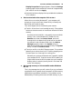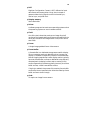
1
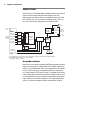
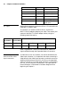
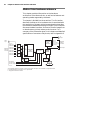
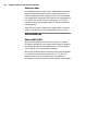
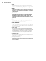
Matrox Orion
Installation and Hardware Reference
Manual no. 10704-101-0200
May 9, 2000
Matrox® is a registered trademark of Matrox Electronic Systems Ltd.
Microsoft®, Windows®, and Windows NT® are registered trademarks of
Microsoft Corporation.
Intel®, Pentium®, and Pentium II® are registered trademarks of Intel
Corporation.
All other nationally and internationally recognized trademarks and
tradenames are hereby acknowledged.
© Copyright Matrox Electronic Systems Ltd., 2000. All rights reserved.
Disclaimer: Matrox Electronic Systems Ltd. reserves the right to make
changes in specifications at any time and without notice. The
information provided by this document is believed to be accurate and
reliable. However, no responsibility is assumed by Matrox Electronic
Systems Ltd. for its use; nor for any infringements of patents or other rights
of third parties resulting from its use. No license is granted under any
patents or patent rights of Matrox Electronic Systems Ltd.
PRINTED IN CANADA
Contents
Chapter 1: Introduction . . . . . . . . . . . . . . . . . . . . . . . . . . . 7
Matrox Orion . . . . . . . . . . . . . . . . . . . . . . . . . .8
Acquisition features . . . . . . . . . . . . . . . . . . .8
Matrox MGA-G400 . . . . . . . . . . . . . . . . . . . .9
Display features . . . . . . . . . . . . . . . . . . . . . .9
Video encoding . . . . . . . . . . . . . . . . . . . . . .10
Software . . . . . . . . . . . . . . . . . . . . . . . . . . .10
What you need to get started. . . . . . . . . . . . . .11
Inspecting the Matrox Orion package . . . . . . .11
Standard package. . . . . . . . . . . . . . . . . . . .11
Optional parts . . . . . . . . . . . . . . . . . . . . . .12
Handling components. . . . . . . . . . . . . . . . .12
Installation overview . . . . . . . . . . . . . . . . . . . .13
Chapter 2: Hardware installation . . . . . . . . . . . . . . . . . . 15
Installing Matrox Orion . . . . . . . . . . . . . . . . . .16
Connecting external devices . . . . . . . . . . . . . .19
Outputting to external video devices . . . . . .20
Attaching a video input. . . . . . . . . . . . . . . .21
Chapter 3: Installing software . . . . . . . . . . . . . . . . . . . . . 23
Installing the software. . . . . . . . . . . . . . . . . . .24
Matrox Intellicam . . . . . . . . . . . . . . . . . . . . . .24
Chapter 4: Matrox Display Properties and Matrox
PowerDesk . . . . . . . . . . . . . . . . . . . . . . . . . . . . . . . . . . . . . 25
Overview . . . . . . . . . . . . . . . . . . . . . . . . . . . . 26
Configuring your display . . . . . . . . . . . . . . . . 27
Specifying your monitor . . . . . . . . . . . . . . . 27
Additional information . . . . . . . . . . . . . . . . . . 29
Matrox Uninstall Program . . . . . . . . . . . . . . . 29
Chapter 5: Matrox Orion hardware reference . . . . . . . 31
Matrox Orion hardware reference . . . . . . . . . . 32
Acquisition section . . . . . . . . . . . . . . . . . . . . . 33
Video decoder . . . . . . . . . . . . . . . . . . . . . . 33
RGB digitization section. . . . . . . . . . . . . . . 35
Pixel Converter . . . . . . . . . . . . . . . . . . . . . 37
Trigger. . . . . . . . . . . . . . . . . . . . . . . . . . . . 38
Display section. . . . . . . . . . . . . . . . . . . . . . . . 39
Video encoder . . . . . . . . . . . . . . . . . . . . . . 40
Data interfaces. . . . . . . . . . . . . . . . . . . . . . . . 40
Matrox MGA G400 . . . . . . . . . . . . . . . . . . . 40
AGP and PCI interface . . . . . . . . . . . . . . . . 41
Appendix A: Troubleshooting . . . . . . . . . . . . . . . . . . . . . 43
Troubleshooting . . . . . . . . . . . . . . . . . . . . . . . 44
Common problems and solutions . . . . . . . . . . 44
Installation problems . . . . . . . . . . . . . . . . . 44
Grabbing problems . . . . . . . . . . . . . . . . . . 46
Video display problems . . . . . . . . . . . . . . . .46
Problems during application development. .48
Contacting Matrox . . . . . . . . . . . . . . . . . . . . .49
Appendix B: Technical information . . . . . . . . . . . . . . . . 51
Board summary . . . . . . . . . . . . . . . . . . . . . . .52
Global information . . . . . . . . . . . . . . . . . . .52
Technical features . . . . . . . . . . . . . . . . . . .52
Default settings . . . . . . . . . . . . . . . . . . . . .53
Board input and output connectors . . . . . . . .53
Expanded video I/O connector . . . . . . . . . .54
VGA output connector . . . . . . . . . . . . . . . .56
Video input and TV output connectors . . . .57
Specifications . . . . . . . . . . . . . . . . . . . . . . . . .58
Electrical . . . . . . . . . . . . . . . . . . . . . . . . . .58
Environmental . . . . . . . . . . . . . . . . . . . . . .58
Appendix C: Glossary . . . . . . . . . . . . . . . . . . . . . . . . . . . 59
Index
Regulatory Compliance
Product Support
Chapter 1: Introduction
This chapter outlines the key features of Matrox Orion.
8
Chapter 1: Introduction
Matrox Orion
Matrox Orion is a frame grabber, capable of acquiring color and
monochrome images from standard video sources and
displaying them. Matrox Orion is available in both AGP and
PCI versions. You can use Matrox Imaging Library (MIL) or
any of its derivatives to program your Matrox Orion.
TV
output
Video
input
CVBS1/Y1/R1
CVBS5/Y3/R2
CVBS2/C1/G1
Expanded CVBS6/C3/G2
video I/O
connector* CVBS3/Y2/B1
CVBS7/Y4/B2
CVBS4/C2/S1
CVBS8/C4/S2
NTSC/PAL
Video
Encoder
2:1
MUX
2:1
MUX
/
4:1
MUX
2:1
MUX
NTSC/PAL
Video
24
Decoder /
Pixel Converter
8
/
Ext. Trigger**
TTL Aux. Input
TTL Aux. Output
24
/
2
2
/
TTL Sync
5
8
/
Expanded
video I/O
connector*
VGA output
Matrox
G400
/
2:1
MUX
RGB
Digitizer
R or C
G or Y
B or CVBS
Sync or CVBS
128
/
32
Frame buffer
(32 Mbytes)
AGP to PCI
Bridge***
/
AGP or PCI bus
* The expanded video I/O connector is used for both inputs and outputs, and is located on a separate bracket.
** The external trigger can be either TTL or opto-isolated.
*** Only present on the PCI version.
Acquisition features
Matrox Orion can acquire video from different types of standard
video sources using its video decoder and its RGB digitization
section. The video decoder path can accept monochrome video
in RS-170/CCIR format, or composite (CVBS) or component
(Y/C) color video in NTSC/PAL format. The decoder can convert
color video streams to BGR32 packed for transfers to Host, and
YUV16 packed (YUYV) for transfers to the display, with either
square pixels or CCIR-601 resolutions. The RGB digitization
section can capture component RGB analog video. Matrox
Matrox Orion
9
Orion features eight software-selectable input channels to
which you can attach up to eight CVBS, four Y/C, or two RGB
cameras and then grab from one of these cameras.
Matrox Orion includes three 256x8-bit programmable input
lookup-tables (LUTs) to remap the video stream.
Matrox Orion can accept an opto-isolated differential trigger
input or a TTL trigger input to capture the next valid frame or
field.
Matrox MGA-G400
Matrox Orion features the Matrox MGA-G400 controller. This
controller uses a 32-Mbyte frame buffer to store data for display
and for transfers to the Host. When in bus master mode, Matrox
MGA-G400 can perform transfers without requiring
continuous Host intervention.
The AGP version of the Matrox Orion board is capable of AGP
1X and 2X speeds, depending on the chipset in your computer.
Display features
The Matrox MGA-G400 uses a 32-bit wide, master AGP or PCI
Host interface, and includes two independent CRT controllers.
Matrox Orion uses the primary CRT controller for the main
display (VGA) output, and the secondary CRT controller as an
independent secondary (TV) display output.
Overlay capabilities
Controlled by the MGA-G400 chip, Matrox Orion’s 32-Mbyte
frame buffer is used to store both graphics and video data. The
MGA-G400 chip is capable of dynamically allocating both an
overlay and underlay frame buffer surface; these can be
combined by the controller to display a live video window on
your Windows desktop with non-destructive annotations.
Because of these capabilities, Matrox Orion supports MIL’s
DirectDraw underlay-surface display architecture.
Matrox Orion can deliver a true color (32-bit) image display
with a 32-bit color overlay, for a completely true color display
at up to 1280x1024 resolution with a maximum vertical refresh
rate of 75 Hz; note that this is dependent on your monitor.
10
Chapter 1: Introduction
The MGA-G400 integrates DACs and three 256x8-bit output
LUTs. These LUTs can be used by the overlay frame buffer
surface. In addition, the MGA-G400 performs Chroma keying,
which allows non-destructive overlay of graphics on a static
image or live video.
Video encoding
Driven by the secondary CRT controller, the NTSC/PAL/RGB
video encoder provides an additional video output with overlay,
from Matrox Orion to external video devices (for example, TVs
or VCRs). The video encoder can be programmed to output
either component RGB video or both composite and Y/C
(NTSC/PAL) video in either square pixel or CCIR-601
resolutions.
Software
You can purchase one or more of the Matrox Imaging software
products that support the Matrox Orion board. These are the
Matrox Imaging Library (MIL) and its following derivatives:
MIL-Lite, ActiveMIL, and ActiveMIL-Lite. All Matrox Imaging
software is supported under Windows.
MIL
MIL is a development library which provides an extensive list
of commands used to capture, process, analyze, transfer,
display, and archive images. Processing and analysis
operations include: spatial filtering, morphology,
measurements, blob analysis, optical character recognition
(OCR), pattern matching, matrix/bar code reading, and
calibration.
MIL-Lite
MIL-Lite is a subset of MIL. It includes all the MIL commands
for image acquisition, transfer, display control, and archiving.
ActiveMIL
ActiveMIL is a set of ActiveX controls that are based on MIL.
ActiveMIL was designed for rapid application development
(RAD) tools, such as Microsoft’s Visual Basic. ActiveMIL is
included with MIL.
ActiveMIL-Lite
ActiveMIL-Lite is a subset of ActiveMIL. It includes all the
ActiveX controls for image acquisition, transfer, display control,
and archiving. ActiveMIL-Lite is included with MIL-Lite.
What you need to get started
Intellicam
11
Matrox Intellicam is an interactive Windows program that
allows fast camera interfacing and provides interactive access
to all the acquisition features of your Matrox board. Matrox
Intellicam can be used to fine tune acquisition settings on your
Matrox Orion board. Intellicam is included with both MIL and
MIL-Lite.
What you need to get started
To begin using Matrox Orion, you need the following:
■
Computer with an empty AGP or PCI expansion slot and a
Pentium-II-class processor or better for the AGP version, or
a Pentium-class processor or better for the PCI version. Note
that the AGP version of the Matrox Orion supports AGP 1X
on chipsets such as Intel 440LX, and AGP 2X on chipsets such
as Intel 440BX, 820, and 840.
■
Windows: See your software package for supported
environments and RAM requirements.
■
A CD drive, and a hard disk or network drive on which to
install the Matrox Orion software.
Inspecting the Matrox Orion package
When you unpack your Matrox Orion package, you should
check its contents. Note that optional parts will only be included
if ordered. If something is missing or damaged, contact your
Matrox representative.
Standard package
If you ordered Matrox Orion, you should receive the following
items:
■
The Matrox Orion board, the expanded video I/O adapter
bracket, and the flat ribbon cable.
■
The Matrox Orion Installation and Hardware Reference
manual (this document).
12
Chapter 1: Introduction
Optional parts
You might have also ordered one or more of the following:
■
MIL-32/CD, which includes MIL and ActiveMIL; or
MIL-Lite/CD, which includes MIL-Lite ActiveMIL-Lite. MIL
and MIL-Lite CDs include intellicam.
■
A DBHD44-TO-13BNC input cable with a high density
44-pin male connector and thirteen BNC-type connectors. Six
BNC-TO-SVHS adaptor cables for Y/C input are shipped with
the DBHD44-TO-13BNC cable, although only four can be
used.
■
DH44-TO-13BNC/O input cable with a high density DB-44
male connector on one end and both open-ended wires and
thirteen BNC-type connectors on the other end. This cable is
required if you want to connect to synchronization and
control signals.
Handling components
The electronic circuits in your computer and the circuits on
Matrox Orion are sensitive to static electricity and surges.
Improper handling can seriously damage the circuits.
▲ Caution
■
Drain static electricity from your body by touching a metal
fixture (or ground) before you touch any electronic
component.
■
Avoid letting your clothes come in contact with the circuit
boards or components.
Before you add or remove devices from your system, always
turn off the power to your computer and all its peripherals.
Installation overview
13
Installation overview
The installation procedure consists of the following steps:
1. Complete the hardware installation as described in
Chapter 2. If you have any problems, refer to Appendix A.
2. Complete the software installation as described in
Chapter 3.
3. Familiarize yourself with the MGA PowerDesk by reading
Chapter 4.
More information
For in-depth hardware information, refer to Chapter 5.
For technical specifications and connector pinout descriptions,
see Appendix B.
Conventions
Note that in this manual, the term Host refers to your computer.
Also note that we refer to and give examples specific to MIL-Lite
in this manual. However, anything that can be accomplished
with MIL-Lite can also be accomplished with MIL, ActiveMIL,
and ActiveMIL-Lite.
Need help?
Appendix A offers solutions to potential problems. If your
Matrox Orion installation questions are not answered in this
manual, contact your local Matrox representative or the Matrox
Imaging Customer Support group; refer to the Product Support
section at the back of this manual for email addresses and
phone numbers of Matrox’s offices. Or for up-to-the minute
release and customer support information, visit our web site:
http://www.matrox.com/imaging
In the unlikely event of a failure, the warranty and Product
Assistance Request Form at the back of this manual outline
return conditions and procedures.
14
Chapter 1: Introduction
Chapter 2: Hardware
installation
This chapter explains how to install the Matrox Orion board
in your computer.
16
Chapter 2: Hardware installation
Installing Matrox Orion
Before you install your board, some precautionary measures
must be taken. Turn off power to the computer and its
peripherals, and drain static electricity from your body (by
touching a metal part of the computer chassis). Next, proceed
with the following steps to install your board.
Steps for installation
1. Remove the cover from your computer using the
instructions from your computer manual.
2. If you have the AGP version of Matrox Orion, check that
the AGP slot is empty. If it is not, remove the current AGP
board from your system to make room for your Matrox
Orion board. If you have the PCI version of Matrox Orion,
check that you have an empty PCI slot. If you do not have
an empty slot, remove a PCI board from your system to
make room for your Matrox Orion board. Also, remove any
AGP board present in your system.
The main bracket of the Matrox Orion board has one BNC
video input connector. If you plan to connect multiple video
input devices, or a device that requires additional
synchronization and control signals, you will need to install
the expanded video I/O adapter bracket. Ensure, then, that
the slot next to the AGP or PCI slot is free so that you will
be able to install the second bracket.
3. If present, remove the blank metal plate located at the back
of the selected slot(s). Keep the removed screw(s); you will
need it to fasten the Matrox Orion board.
4. You must remove any VGA board present in your computer,
or if you have a built-in VGA on your motherboard, you
must disable it. Also, you must switch any other display
board to dual-screen mode. To do so, refer to your system’s
or board’s manuals.
Installing Matrox Orion
17
5. Lower the board gently into the slot.
SCREW
MATROX OR
METAL
PLATE
ION
AGP or PCI BOARD SLOT
6. Once the board is perfectly aligned, press the board firmly
but carefully into the slot.
7. Anchor the board by replacing the screw that you removed.
If you do not plan to connect a video input device to the
expanded video I/O adaptor bracket, proceed to step 10.
8. Attach the expanded video I/O connector on the adapter
bracket to the expanded video I/O interface connector using
the ribbon cable.
Expanded video I/O
connector (DB-44)
Expanded video I/O
adapter bracket
Expanded video I/O
interface connector
Ribbon cable
Stripe
Video input connector
TV output connector
VGA output connector
(DB-15)
Note: AGP version presented here. PCI version might vary slightly.
18
Chapter 2: Hardware installation
9. Secure the adapter bracket with the reserved screw.
A board installed in an AGP or PCI slot should look like this:
Note: AGP version presented here.
PCI version might vary slightly.
10. Replace the cover of your computer.
11. Attach your monitor(s) and input video sources. For details,
see the Connecting external devices section.
12. Turn on your computer.
Under Windows 2000, when you boot your computer,
Windows’ Plug-and-Play system will detect a new
Multimedia Video Device and you will be asked to assign it
a driver. At this point, you should click Cancel because the
driver will be installed during the installation of MIL or one
of its derivatives.
Connecting external devices
19
Connecting external devices
Matrox Orion has four external interface connectors of which
three are located on its main bracket.
Expanded video I/O
connector (DB-44)
Expanded video I/O
adapter bracket
Expanded video I/O
interface connector
Ribbon cable
Stripe
Video input connector
TV output connector
VGA output connector
(DB-15)
Note: AGP version presented here. PCI version might vary slightly.
■
Video input connector. A BNC connector used to receive
analog composite video.
■
TV output connector. A BNC connector used to output
analog composite video to an external device, such as a
television or VCR.
■
VGA output connector. A 15-pin D-type (DB-15) connector,
used to output analog video and digital synchronization
signals to the monitor. The pinout is compatible with VGA
monitors.
■
Expanded video I/O connector. Located on a separate
bracket. A standard, high density, 44-pin, D-type (DB-44)
connector, used to input analog video and input/ouput
synchronization signals, as well as the encoder’s output
signals.
20
Chapter 2: Hardware installation
Outputting to external video devices
Connecting a monitor
Matrox Orion works with VGA and high-resolution monitors.
To display the standard video output of Matrox Orion:
1. If your monitor has impedance switches, set the switches
for the red, green, and blue inputs to 75 ohms, as shown in
the illustration below. Set the switches for the
synchronization inputs according to your monitor’s manual.
In most cases, these switches should be set to high
impedance and external sync mode.
15-pin
Video Output
Connector
Expanded Video I/O
Connector
Separate
Cable
75
R
75
B
Video
75
G
INT
HSYNC
75
VSYNC
EXT
(BNC)
RED
(BNC)
BLUE
(BNC)
GREEN
(BNC)
WHITE
or
GRAY
(BNC)
BLACK
2. Connect the monitor to Matrox Orion's 15-pin female VGA
output connector (DB-15). If your monitor has a DB-15
connector, use the standard DB-15 to DB-15 cable that is
usually provided with your monitor. If your monitor has 5
BNC-type connectors, use the standard DB-15 to 5-BNC
cable that is usually supplied with such monitors.
Connecting external devices
Connecting external
devices to the
encoder’s output
21
Matrox Orion’s encoder can output NTSC/PAL and RGB video,
through the expanded video I/O connector, and composite video
in NTSC/PAL through the TV output connector. To connect
devices to the expanded video I/O connector, use the optional
DBHD44-TO-13BNC cable, connecting the wires as described
below:
Wires
White (5)
Signals
RED_C_OUT
Expected output
Encoded Video Output
(C or red).
Yellow (6) GREEN_Y_OUT
Encoded Video Output
(Y or green).
Purple (7) BLUE_COMP_OUT Encoded Video Output
(CVBS or blue).
To connect to the TV output connector, use a standard video
cable (available from your local electronics store). Note that
devices connected to the TV output connector are connected to
the BLUE_COMP_OUT line without a multiplexer. This means
that the signal can be received from both the TV output and
expanded video I/O connectors simultaneously; however,
connecting to both will result in poor video quality. The signal
path for these connectors is illustrated in the block diagram at
the beginning of Chapter 1.
Attaching a video input
Connecting external
devices to the
expanded video I/O
connector
You can attach video sources to Matrox Orion’s expanded video
I/O connector using the optional DBHD44-TO-13BNC. This
cable has thirteen BNC connectors, and a DB-44 plug. The
DBHD44-TO-13BNC cable supports eight video input signals,
3 video output signals (described in the above table), and 2
trigger signals. The wires of this cable are color-coded and
numbered as follows:
Wires on 13BNC Cable
Signals
Expected Input
RED (1)
VID_IN1
Analog Video Input1 or Y1
GREEN (2)
VID_IN2
Analog Video Input2 or C1
BLUE (3)
VID_IN3
Analog Video Input3 or Y2
BLACK (4)
VID_IN4
Analog Video Input4 or C2
22
Chapter 2: Hardware installation
Y/C input
Wires on 13BNC Cable
Signals
Expected Input
BROWN (8)
VID_IN5
Analog Video Input5 or Y3
ORANGE (10)
VID_IN6
Analog Video Input6 or C3
PINK (11)
VID_IN7
Analog Video Input7 or Y4
LIGHT GREEN (12)
VID_IN8
Analog Video Input8 or C4
GRAY (13)
OPTOTRIG External trigger input
LIGHT BLUE (9)
TRIGGER
Non-protected TTL
trigger input
Matrox Orion supports a maximum of four Y/C inputs with the
DBHD44-TO-13BNC cable.
To connect a Y/C camera to Matrox Orion, connect the
BNC-TO-SVHS adaptor cables to your cable. Then attach your
camera to the BNC-TO-SVHS adaptor cables, using the
following cable information.
Connectors Wires on
Wires on DBHD44-TO-13BNC
on camera BNC-TO-SVHS
Luminance
Blue (Y)
Chrominance Green (C)
Red (1)
Blue (3)
Brown (8)
Pink (11)
Green (2)
Black (4)
Orange (10) Light Green (12)
Refer to Appendix B: Technical information for additional
signals offered through the Expanded video I/O connector.
Connecting external
devices to the video
input connector
A video source, such as a camera, can also be attached to the
video input connector. It is important that when connecting a
video source to the video input connector, you do not connect an
additional video source to the VID_IN1 pin on the expanded
video I/O connector. The video input connector is connected to
the VID_IN1 line without a multiplexer. The signal path for
these connectors is illustrated in the block diagram at the
beginning of Chapter 1.
Chapter 3: Installing software
This chapter explains how to install the Matrox Orion
software.
24
Chapter 3: Installing software
Installing the software
Once the Matrox Orion board is installed, read the
documentation of your Matrox software package for
installation and licensing information. In general, you will have
to place the installation CD of the package in the appropriate
drive; the setup.exe program will run automatically. In some
cases, installation of a hardware key is required.
Matrox display drivers
In order to take advantage of Matrox Orion’s special display
features, install the Matrox MGA driver included on the CD.
This will create a new Windows group called Matrox
PowerDesk. The Matrox PowerDesk includes utilities, such as
the Matrox Display Properties utility, which allow you to
control your display settings. The Matrox PowerDesk group, as
well as the Matrox Display Properties utility, are described in
Chapter 4.
❖ If you already have another version of the Matrox display
driver installed on your system, we recommend that you
uninstall it and install the version on your software CD.
After installation, read any readme file(s) recommended by the
installation program.
Matrox Intellicam
MIL-Lite uses digitizer configuration format (DCF) files to
configure the camera interface on Matrox digitizers. The DCF
defines among other things video timing signals and the video
data format. Matrox Intellicam can be used to fine tune
acquisition settings of your Matrox Orion board.
For more information about Matrox Intellicam, refer to the
Matrox Intellicam User Guide.
Chapter 4: Matrox Display
Properties and Matrox
PowerDesk
This chapter provides information about the Matrox
Display Properties dialog box, as well as the Matrox
PowerDesk group.
26
Chapter 4: Matrox Display Properties and Matrox PowerDesk
Overview
This chapter discusses how to configure your display settings
to take advantage of Matrox Orion’s special display features.
The display section of Matrox Orion is powered by the
Matrox G400 graphics display controller. Matrox Orion uses
the Matrox display drivers to drive the display section. When
installing the drivers, the Matrox PowerDesk tools are also
installed, which permit you to configure the display settings on
your Matrox Orion. Chapter 3 explains how to install software
for your Matrox Orion board. The drivers have been installed
correctly if you see the Matrox QuickDesk icon in your Windows
taskbar.
The display resolution, display mode, and desktop size are set
using the Matrox Display Properties utility, one of the Matrox
PowerDesk tools.
❖ If you have a different version of the Matrox Display
Properties utility or Matrox PowerDesk, some information
might be different; for the most up-to-date information, refer
to the on-line help of these products.
Configuring your display
27
Configuring your display
You can customize your display settings with the Matrox
Display Properties utility. To lauch this utility under:
■
Windows 2000. Select Properties from the Windows
desktop context-menu. From the Display Properties window,
select the Settings property page and then click on the
Advanced button.
■
Windows NT 4.0. Select Programs from the Start menu.
From the presented submenu, select Matrox
PowerDesk NT, and then Matrox Display Properties.
Specifying your monitor
Before configuring your display settings, it is recommended
that you specify your monitor. By default, the Matrox display
drivers assume that you have a 60 Hz monitor. If your monitor
is capable of higher refresh rates, you can customize your
monitor.
❖ If incorrect software monitor settings are applied, some
monitors can be permanently damaged. For more
information, see your monitor’s manual.
Windows 2000
Under Windows 2000. When using a Plug-and-Play (DDC)
monitor, Windows should automatically use the correct settings
for your monitor.
To install a monitor other than a Plug-and-Play (DDC) monitor
or to customize or verify your Windows monitor settings:
1. Click on the Monitor property page of the Matrox Display
Properties utility.
2. If the monitor name listed does not match your monitor,
click on the Properties button and select the Driver
property page.
3. To install the proper device driver for your monitor, click on
the Update Driver button and follow the on-screen
instructions.
28
Chapter 4: Matrox Display Properties and Matrox PowerDesk
Windows NT 4.0
Under Windows NT 4.0. When using a Plug-and-Play (DDC)
monitor, Windows should automatically use the correct settings
for your monitor. To make sure the correct monitor is selected
in Windows:
1. Click on the Monitor property page of the Matrox Display
Properties utility.
2. Make sure the Plug-and-Play (DDC) monitor option is
selected. If so, the Matrox display driver automatically uses
the correct settings for your monitor. If not, select the
Plug-and-Play (DDC) monitor option, and then click on
Apply.
If you want to customize your Windows monitor settings, click
on the Settings property page and follow on-screen
instructions.
If you want to install a monitor other than a Plug-and-Play
(DDC) monitor, click on the Monitor property page. Select the
Matrox monitor option and follow on-screen instructions.
Other considerations
■
If you are using BNC connectors with a Plug-and-Play
monitor, the Plug-and-Play feature of your monitor cannot be
used. To use the Plug-and-Play feature of your monitor, use
the 15-pin connector at the back of your monitor instead of
the BNC connectors.
■
In Windows 2000, Matrox monitor settings are based on
Windows monitor settings. If you change your Windows
monitor settings, you might have to reselect or readjust your
Matrox monitor settings.
For more information on Windows monitor settings, see
Windows documentation.
Additional information
29
Additional information
Additional information regarding the Matrox Display
Properties utility and other Matrox PowerDesk tools, is
available in the on-line help for those products, as well as the
following resources:
Windows 2000
■
Select Properties from the Windows desktop context-menu.
From the Display Properties window, select the
Information property page and then click on View Readme
File button.
Windows NT 4.0
■
Select Programs from the Start menu. From the presented
submenu, select Matrox PowerDesk NT and then select
one of the following :
❐
Matrox PowerDesk Guide.
❐
ReadMe file.
❐
Select Matrox Display Properties and then
Information.
Matrox Uninstall Program
The Matrox Uninstall Program allows you to disable or remove
all or part of the Matrox Windows software. When you use this
program, all the files you choose to uninstall are deleted from
your hard disk, and all entries pertaining to these files are
removed from your Windows registry.
To use the Matrox Uninstall Program, click on Matrox
PowerDesk Uninstall from the Matrox PowerDesk group. In
the Matrox Uninstall Program dialog, you can choose to do a
complete or a partial uninstallation of Matrox PowerDesk.
30
Chapter 4: Matrox Display Properties and Matrox PowerDesk
Chapter 5: Matrox Orion
hardware reference
This chapter explains the hardware architecture of the
Matrox Orion, as well as the available features and modes
of operation.
32
Chapter 5: Matrox Orion hardware reference
Matrox Orion hardware reference
This chapter provides information on the hardware
architecture of the Matrox Orion, as well as the features and
operating modes supported by the board.
The chapter is divided into three sections. The first section
describes the Matrox Orion hardware that is associated with
the acquisition of images, while the second section describes
the hardware related to the display of images. The third section
discusses the data interfaces, and how to transfer images from
on-board memory to Host memory and vice versa. For a
summary of the information given in this chapter and detailed
specifications of connectors and pinouts, refer to Appendix B.
TV
output
Video
input
CVBS1/Y1/R1
CVBS5/Y3/R2
CVBS2/C1/G1
Expanded CVBS6/C3/G2
video I/O
connector* CVBS3/Y2/B1
CVBS7/Y4/B2
CVBS4/C2/S1
CVBS8/C4/S2
NTSC/PAL
Video
Encoder
2:1
MUX
/
2:1
MUX
4:1
MUX
2:1
MUX
NTSC/PAL
Video
24
Decoder /
Pixel Converter
8
/
Ext. Trigger**
TTL Aux. Input
TTL Aux. Output
2
2
/
24
/
TTL Sync
5
8
/
Matrox
G400
/
2:1
MUX
RGB
Digitizer
R or C
G or Y
B or CVBS
Sync or CVBS
128
/
32
Frame buffer
(32 Mbytes)
AGP to PCI
Bridge***
/
AGP or PCI bus
* The expanded video I/O connector is used for both inputs and outputs, and is located on a separate bracket.
** The external trigger can be either TTL or opto-isolated.
*** Only present on the PCI version.
Expanded
video I/O
connector*
VGA output
Acquisition section
33
Acquisition section
The acquisition section of Matrox Orion provides two different
methods of capturing images. It uses a video decoder to capture
monochrome video in RS-170/CCIR format, or composite
(CVBS) or component (Y/C) color video in NTSC/PAL format.
Matrox Orion uses an RGB digitization section to acquire
monochrome or component RGB analog video from standard
cameras.
Matrox Orion has three 256x8-bit input LUTs, which are
included to map the video data stream. Matrox Orion also
supports an external synchronous trigger which can be used for
capturing the next valid field or frame. The board can also
accept an external analog composite sync input.
When digitizing data on Matrox Orion, the values 0 and 255
are reserved; therefore, the range of possible pixel values spans
from 1 to 254. See the Pixel Converter section.
Setting up the grab
section
To program the acquisition section, allocate it (using MIL-Lite
MdigAlloc()) with an appropriate DCF (supplied or created). If
required, you can make minor adjustments to common
acquisition parameters at run time (using MIL-Lite Mdig...()
commands). For more specialized adjustments, use the Matrox
Intellicam program to adjust the DCF file.
Video decoder
A multi-standard video decoder is used to convert analog
monochrome video in RS-170/CCIR format, or composite
(CVBS) or component (Y/C) color video in NTSC/PAL format, to
digitized video. The decoder can output the video stream in
either BGR32 packed or YUV16 (YUYV) packed formats.
34
Chapter 5: Matrox Orion hardware reference
Sampling Rates for NTSC/PAL Standards
Video format
Square Pixels
CCIR-601
NTSC
12.27 MHz
(640x480)
13.5 MHz (720x480)
PAL
14.75 MHz
(768x576)
13.5 MHz (720x576)
The video decoder also features an automatic gain control
(AGC). However, you can disable this feature (MIL-Lite
MdigControl() with M_GRAB_AUTOMATIC_INPUT_GAIN set to
M_DISABLE) and adjust the gain manually (MdigControl() with
M_GRAB_INPUT_GAIN).
Phase-locked loop
The decoder incorporates a phase-locked loop (PLL), and
outputs a clock signal at three frequencies. When analog data
passes through the decoder, the sync signals are extracted by
the PLL. The clock signals that exit the decoder depend on the
type of analog signal and the resolution. The signal type, the
generated clock frequencies, and display resolution are
described in the table below:
CCIR-601
Square Pixels
Signal type
NTSC
PAL
NTSC
PAL
Clock
Frequency
27.0 MHz 27.0 MHz 24.54 MHz
29.5 MHz
Resolution
720 x 480 720 x 576 640 x 480
768 x 576
Active Pixels
720
720
640
768
Active Lines
480
576
480
576
Acquisition section
35
RGB digitization section
The RGB digitization section includes circuitry to select,
amplify, and filter the video signal prior to sending it to the
three independent analog-to-digital converters (A/D
converters).
RGB input
The RGB digitization section can be connected to and switch
between two RGB or up to six monochrome cameras. The
synchronization signal can be on any component of the RGB
input or can be received on the separate sync input (VID_IN4
or VID_IN8).
The RGB digitization section can accept simultaneous input
from three genlocked monochrome cameras. The inputs are
stored in separate color bands of the same buffer; the buffer can
be in planar format.
The MIL-Lite MdigChannel() command can be used to switch
between cameras (or channels).
Low pass filter
The input low-pass filtering stage is used to limit high
frequency noise and aliasing effects at the input of the A/D
converter. The filter used on Matrox Orion is a 4th order
Butterworth filter with a cutoff frequency of 8 MHz. If required,
this filter can be bypassed by changing the appropriate setting
in the DCF with Matrox Intellicam.
Gain
The RGB digitization section has selectable gains that affect all
three RGB signals. This allows you to optimize the range of
video input signals. You can change the gain using the MIL-Lite
MdigControl() command.
36
Chapter 5: Matrox Orion hardware reference
A/D converters
Input video
signal
amplitude
(excluding
sync)
Total input Required
video signal gain setting
amplitude
(includin!g
sync)
MIL
0.0 V up to 0.5 V
0.0 - 0.7 Vpp 4
M_GAIN3
0.5 V up to 0.7 V
0.7 - 1.0 Vpp 2.8 (Default)
M_GAIN2
0.7 V up to 1.0 V
1.0 - 1.4 Vpp 2
M_GAIN1
1.0 V up to 2.0 V
1.4 - 2.8 Vpp 1.3
M_GAIN0
Matrox Orion uses three independent 10-bit analog/digital
converters, one for each R, G, and B channel. Although 10-bit
converters are used, the converters only output the 8
most-significant bits of data. The converter can operate at the
maximum pixel clock frequency of the decoder (14.75 MHz)1.
In addition, the converter’s black and white reference levels can
be adjusted individually. The black and white reference levels
can be adjusted between 0.6 V to 1.6 V and 1.6 V to 2.6 V
respectively, in increments of 10.23 mV (98 distinct
adjustments). Use the MIL-Lite MdigReference() command to
set the black and white reference levels.
1. The pixel clock frequency is half of the decoder’s clock frequency.
Acquisition section
37
Pixel Converter
The Pixel Converter serves as an interface between Matrox
Orion’s digitization section and the G400 chip. The Pixel
Converter contains the following stages: Pixel Formatters 1 and
2, input lookup tables, Color space converter, and Capture
Control.
Pixel Converter
PF 1
From RGB
path or
decoder
LUTs
MUX
Color space
converter
PF 2
To G400
Capture Control
Pixel Converter
The Pixel Converter provides all signals required by the
digitization section, and formats the digitized data for the
MGA-G400. For example, the Pixel Formatter 2 can extract the
Y component from a YUV stream, or any component from the
RGB stream and feed it to the G400. In addition, the color-space
converter can convert RGB (BGR32) data to YUV16 (YUYV).
Due to the nature of the Matrox MGA-G400 controller, the data
that is passed to the G400 cannot have the values 0 and 255;
Pixel Formatter 2 automatically remaps these values to 1 and
254, respectively, before passing the data to the G400.
Input lookup-tables
Matrox Orion has three 256x8-bit input LUTs, allowing
independent re-mapping of three 8-bit input streams. Note that
only RGB data can use the LUTs; YUV data bypasses the LUTs.
Capture Control
The Capture Control receives clock and sync signals from video
input devices, and sets the conditions under which to start and
end the grab. Examples of grabbing conditions are whether to
grab one or two fields per frame, or whether to start the grab
on an odd or even field.
38
Chapter 5: Matrox Orion hardware reference
Trigger
Matrox Orion accepts an external trigger input which allows
image acquisition to be synchronized to external events
(MIL-Lite MdigControl()). The trigger initiates the capture of
the next valid frame or field.
Direct TTL trigger
Trigger signals can be received directly (pin 20 on the expanded
video I/O connector) in TTL format. The amplitude of the TTL
level signal must not exceed 5 V. A signal over 2 V is considered
high, while anything less than 0.8 V is considered low. The
transition of 0.8 V to 2 V is considered to be the rising edge.
The trigger signal’s pulse width must be greater than one pixel.
The pulse width is determined by the following:
1
Minimum pulse width = ------------------------------------------------------- × 2
pixel frequency (MHz)
For example, if the pixel frequency is 24.54 MHz, the minimum
pulse width is 1/24.54 MHz x 2 ≈ 82 nsec. Therefore, the
minimum pulse width must be greater than or equal to 82 nsec.
▲ Caution
Opto-coupled trigger
The direct TTL trigger input is not protected or conditioned.
Use it with caution.
Trigger signals connected to the OPTOTRIG+ (pin 35) and
OPTOTRIG- (pin 34) input pins, pass through an opto-coupler,
a device that protects the board from outside surges. The
voltage difference across OPTOTRIG+ and OPTOTRIG- must
be between 4.05 V and 9.16 V for high level voltage, and
between -5.0 V and 0.8 V for low level voltage.
Display section
39
Display section
To drive the display section, Matrox Orion uses the Matrox
MGA-G400 graphics display controller. It has a 128-bit wide
memory interface with the AGP or PCI bus and stores both
graphics and video data in the 32-Mbyte frame buffer
(SDRAM). The MGA-G400 chip is capable of dynamically
allocating both an overlay and underlay frame buffer surface;
these can be combined by the controller to display a live video
window on your Windows desktop with non-destructive
annotations. A 256 Kbyte Flash Memory is used to
permanently store the Video BIOS.
Although Matrox Orion has an on-board MGA-G400, the
Matrox Orion architecture can only support a true color (32-bit)
image display with a 32-bit color overlay at a maximum
resolution of 1280x1024.
Underlay frame buffer
surface
The underlay frame buffer surface is typically used to display
video data. The size of this surface is the same size as the image
selected to the display, and its data format is YUV16 (YUYV)
for color buffers, and 8-bit monochrome for monochrome
buffers.
Overlay frame buffer
surface
The overlay frame buffer surface is used for both displaying the
desktop, and overlaying non-destructive graphic annotations
on your image. The size of this surface is the same as the
desktop, and can only be displayed in 8-bit monochrome or
32-bit color (BGR32 packed).
See Chapter 4: Matrox Display Properties and Matrox
PowerDesk to set your display properties.
40
Chapter 5: Matrox Orion hardware reference
Video encoder
In the display section, an NTSC/PAL video encoder provides an
additional video output with overlay from Matrox Orion to
external video devices (for example, VCRs). The video encoder
can output either component RGB video or both composite and
Y/C (NTSC/PAL) video in either square pixel or CCIR 601
resolutions. Note that composite and Y/C video is outputted
simultaneously.
Note that if the input is operating in square pixels, then the
output must operate in the same resolution and vice versa.
Data interfaces
Matrox MGA G400
Matrox MGA-G400 controls the Host interface. It uses the
32-Mbyte frame buffer to store data when transferring data to
the display, and also stores grabbed data in the frame buffer
until the AGP or PCI bus becomes available.
Matrox MGA-G400 transfers the data at high transfer speeds
in one direction at a time across the AGP or PCI bus. For
example, Matrox Orion can grab into a Host buffer for
processing, and then transfer the resulting data to the display.
Data interfaces
41
AGP and PCI interface
The PCI version of the Matrox Orion is capable of a peak data
transfer rate of 132 Mbytes/sec.
With the AGP version of the Matrox Orion, data can be
transferred at one of two speeds which are outlined in the table
below:
AGP bus speed
1X
2X
Peak transfer rate
(Mbytes/sec)
266
532
The data transfer rate between the bus master and the target
memory is highly dependent on the Host chipset. To operate at
2X transfer speeds, you will require a chipset that supports this
transfer speed, such as the Intel 440BX.
42
Chapter 5: Matrox Orion hardware reference
Appendix A: Troubleshooting
This appendix gives suggestions to help you resolve
potential problems. If your problem is not addressed here,
contact your local Matrox representative, or the Matrox
Imaging Customer Support Group.
44
Appendix A: Troubleshooting
Troubleshooting
If you have problems using your Matrox Orion board, please try
the following:
■
Check for disconnected power cords.
■
Read the Common problems and solutions section in this
chapter.
If your problem is not addressed in this chapter or if the
solutions suggested don’t work for you, contact your local
Matrox representative or the Matrox Imaging Customer
Support group; refer to the Product Support section at the back
of this manual for email addresses and phone numbers of
Matrox’s offices. Or for up-to-the minute release and customer
support information, visit our web site:
http://www.matrox.com/imaging
Common problems and solutions
Installation problems
☛
My computer beeps, hangs shortly after booting, or will
not boot when I turn on the power.
■
☛
Remove any VGA boards and ensure that the motherboard's
VGA is disabled.
After installing the Matrox Windows NT 4.0 driver for my
Matrox Orion, my system does not reboot at the expected
resolution.
This is a problem that you are likely to encounter if the
resolution settings are incorrect or if the Matrox display driver
is not the correct version. These problems can be addressed in
the following ways:
■
To verify the current resolution settings or to change them,
click on the Matrox QuickDesk icon (located in your
Windows taskbar) and select Display Properties. The
Common problems and solutions
45
Display Properties dialog box appears. Select the Settings
property page. Set the resolution to one that is supported by
your monitor and click on Apply.
■
☛
Reinstall the Matrox display driver provided with the Matrox
Orion software.
Device attached to the computer fails to start
When this occurs under Windows NT, your computer will
prompt you to go to the Event Viewer utility to identify the
device that was unable to start.
This could happen due to the following two reasons:
■
The MIL Orion driver is not installed correctly. This problem
could occur due to too much or insufficient allocation of DMA
memory.
Uninstall and reinstall MIL, and specify the correct DMA
setting. Then, under Windows NT, double-click the
Devices icon under the Control Panel, and scroll
through the list to determine if the driver for the device
has started. Under Windows 2000, check the Device
Manager property sheet in the System utility to
determine if the board was installed correctly. The System
utility is under the Control Panel.
■
There is a conflict in the BIOS Setup program. This problem
generally occurs when there is a PCI memory mapping error
or when there is an interrupt-line routing error.
Reinstall your previous VGA board and, if possible, update
your computer BIOS. To get the correct BIOS update, you
might need to know the serial number that your computer
displays when it restarts (usually found in the lower-left
corner of the display).
☛
Not enough memory to allocate buffer under Windows
NT 4.0
This is the message that you will receive if you try to allocate
a grab buffer that is greater than the amount of DMA memory
specified during software installation. This problem can be
addressed by increasing the amount of DMA memory on your
46
Appendix A: Troubleshooting
system. Use the MILConfig utility to do so. Alternatively,
uninstall and reinstall MIL and specify the appropriate amount
of DMA memory.
Grabbing problems
☛
Opto-isolated trigger pulse is not connected
When using the opto-isolated trigger, both OPTOTRIG- and
OPTOTRIG+ signals must be connected. OPTOTRIG- is
usually connected to the ground of the trigger source.
☛
IRQ conflicts
In general, AGP and PCI devices use the same interrupt
signals; therefore, an AGP device can share an interrupt line
(IRQ) with a PCI device. However, sometimes this might not be
possible. The types of difficulties that you might run into are
as follows:
■
BIOS driven IRQ conflict under Windows NT 4.0
In the event that your Matrox imaging board(s) cannot share
an IRQ line, allocate a different IRQ to each device in the IRQ
Configuration Setup section of the BIOS Setup Program
(accessible on bootup).
■
IRQ conflict under Windows 2000
To resolve this problem, either re-assign a different IRQ value
to the AGP slot or change the resource settings in the
Windows’ Device Manager property page. This page can be
accessed using the System utility in the Control Panel.
❖ Note that AGP and PCI devices cannot share interrupt lines
with EISA or ISA devices.
Video display problems
☛
My monitor is blank (or it has shades or spots of gray and
white).
■
Make sure your computer and monitor are plugged in and
turned on.
■
Recheck your connections at both ends of the video cable.
Common problems and solutions
☛
47
■
Check that the brightness and contrast controls are set
correctly.
■
Set the monitor’s switches (if any) to 75 ohms for the video
(RGB) inputs, and set the synchronization to ‘ external’ (and
to high-impedance if this option is available). If there is a
Digital/Analog switch on your monitor, set it to Analog.
■
Ensure that Matrox Orion is sitting evenly and is fully
inserted into its slot. To do this, press the board down firmly.
When I run an application, there is no picture on my video
display. The monitor is blank.
The application you are running might be attempting to select
a resolution that is not supported by your monitor. Check your
monitor’s manual for supported resolutions.
☛
The colors are wrong.
Incorrect colors indicate that either the cabling (for monitors
that do not have a built-in cable) or the monitor impedance is
incorrect.
☛
■
Ensure that the red, green, and blue lines are connected to
the corresponding red, green, and blue monitor inputs (some
monitor input connectors are not in the expected order).
■
Make sure your monitor’s RGB inputs are set to 75 ohms.
Several monitors have individual switches to set the
impedance of the inputs. Make sure that they are all set to
75 ohms.
■
On some computers, you must run a setup program or set
DIP switches to select the main video adapter type. For most
computers, you should select a VGA type. Refer to the user
manual for your computer.
■
Check the cable continuity.
The display is not centered.
Adjust the centering control of your monitor to position the
picture on the screen (refer to your monitor’s manual).
48
Appendix A: Troubleshooting
☛
The picture quality is poor, with a dim picture, poor
contrast, and poor sharpness.
The monitor might be improperly adjusted.
☛
■
Adjust the brightness, sharpness, and contrast controls of
your monitor.
■
Ensure that the cable is correctly and completely inserted at
both ends.
■
Make sure that the RGB input switches are set to 75 ohms.
The picture is broken up, with bad horizontal sync; in
other words, it rolls, jitters, or blinks.
The cables connected to the monitor might not be attached
properly or the monitor might not accept Matrox Orion’s video
settings.
■
Ensure that the synchronization line(s) are properly
connected to your monitor (to identify the sync line(s), refer
to the appropriate monitor configuration in the ‘ Connecting
to a monitor’ section of Chapter 2). If this does not solve the
problem, your monitor might need horizontal setting
adjustments, or it might be defective. Refer to your monitor’s
manual.
■
Ensure that the resolution you specified is valid for your
monitor.
Problems during application development
☛
I’m running an application and the computer ‘hangs’ or
produces unwanted results.
Check for an interrupt, memory or register conflict. Sometimes,
an EISA or ISA device might attempt to use the same
interrupts, register or memory space as Matrox Orion, and this
causes a conflict.
Contacting Matrox
49
Contacting Matrox
Before contacting your local Matrox representative or the
Matrox Imaging Customer Support Group, you will need the
following information:
■
A description of what happened.
■
Computer type, environment, and peripherals (especially
boards sharing the computer with your Matrox Orion).
■
Your board’s serial number (printed on the bar code label).
Use the Product Assistance Request Form at the back of this
manual to record the necessary information.
50
Appendix A: Troubleshooting
Appendix B: Technical
information
This appendix contains information that might be useful
when installing your Matrox Orion board.
52
Appendix B: Technical information
Board summary
Global information
■
Operating systems: Windows. See your software manual for
supported versions of Windows.
■
System requirements: A PC with an AGP or PCI bus and a
Pentium-II processor or equivalent.
Note that the AGP version of the Matrox Orion supports AGP
1X on chipsets such as Intel 440LX, and AGP 2X on chipsets
such as Intel 440BX, 820, and 840. If you need more specific
information regarding potential problems, refer to Appendix
A - Troubleshooting.
Technical features
■
Features eight software-selectable channels, which support
up to eight composite NTSC/PAL (CVBS) video inputs, four
component NTSC/PAL (Y/C) video inputs, or two component
RGB inputs.
■
Accepts an external trigger input, either opto-isolated or
TTL.
■
Three 256x8-bit input LUTs.
■
Programmable reference levels.
■
Automatic and programmable gain control.
■
Arbitrary video scaling (up or down).
■
Maximum display resolution of 1280x1024 for 8-bit and
32-bit images.
■
32-Mbytes of frame buffer memory, from which an underlay
and overlay frame buffer surface can be allocated
dynamically. Once allocated, the underlay frame buffer
surface is displayed in YUV16 (YUYV) format, and is the
same size as the image selected on the display. The overlay
frame buffer surface is displayed in the same resolution as
the desktop, with 8-bit monochrome or true color 32-bit pixels
(BGR32 packed). The overlay frame buffer surface is also the
same size as the desktop.
Board input and output connectors
53
■
Encoder, which provides separate output for standard video.
■
AGP or PCI interface.
Default settings
■
Boot video mode/resolution: VGA Mode 3 (80 characters,
25 lines).
■
Memory map: System-determined (configured on power-up).
Board input and output connectors
Matrox Orion has four external interface connectors, of which
three are located on its main bracket: Video input, TV output,
and VGA output. The expanded video I/O connector is attached
to a DB44 connector on an additional bracket through a ribbon
cable.
Expanded video I/O
connector (DB-44)
Expanded video I/O
adapter bracket
Expanded video I/O
interface connector
Ribbon cable
Stripe
Video input connector
TV output connector
VGA output connector
(DB-15)
Note: AGP version presented here. PCI version might vary slightly.
54
Appendix B: Technical information
Expanded video I/O connector
pin 30
pin 16
pin 44
pin 31
The expanded video I/O connector is a high density DB-44
female connector, and is located on the second bracket. Its
pinout is as follows:
pin 15
pin 1
Pin
Signal
I/O
Description
2
VID_IN8
I
Analog Video Input 8
(CVBS8, C4, or SYNC2).
3-5
GROUND
-
Ground.
8
USER2OUT
O
TTL User Bit output.
9
USER2IN
I
TTL User Bit input.
10
COMP_OUT
O
Encoded Video Output
(CVBS).
11
RED_C_OUT
O
Encoded Video Output
(C or RED).
12
E_CSYNC
O
Synchronization signal from
composite output.
13
VID_IN3
I
Analog Video Input 3
(CVBS3, Y2, or BLUE1).
14
GROUND
-
Ground.
15
VID_IN1
I
Analog Video Input 1 (CVBS1
or Y1, or RED1).
17-18
GROUND
-
Ground.
19
VID_IN6
I
Analog Video Input 6
(CVBS6, C3 or GREEN2).
20
TRIGGER
I
Unprotected TTL TRIGGER
input.
23
VID_IN5
I
Analog Video Input 5
(CVBS5, Y3, or RED2
24
USER1OUT
O
TTL User Bit output.
25-31
GROUND
-
Ground.
33
VID_IN7
I
Analog Video Input 7
(CVBS7, Y4, or BLUE2).
34
OPTOTRIG-
I
Opto-isolated TRIGGER
negative input.
35
OPTOTRIG+
I
Opto-isolated TRIGGER
positive input
39
USER1IN
I
TTL User Bit input.
40
BLUE_COMP_OUT
O
Encoded Video Output
(CVBS or BLUE).
41
GREEN_Y_OUT
O
Encoded Video Output
(Y or GREEN).
Board input and output connectors
Pin
Signal
I/O
Description
42
GROUND
-
Ground.
43
VID_IN4
I
Analog Video Input 4
(CVBS4, C2 or SYNC1).
44
VID_IN2
I
Analog Video Input 2
(CVBS2, C1 or GREEN1).
1, 6, 16, 21-22,
32, 36-38
Not used
55
Use Matrox cable DBHD44-TO-13BNC to interface to this
connector. This cable has thirteen BNC connectors and a
high-density 44-pin D-Subminiature male connector. The
DBHD44-TO-13BNC cable allows you to attach up to eight
analog video sources and a trigger input (either opto-isolated
or TTL). The DBHD44-TO-13BNC cable also has 3 BNC
connectors for encoded video output of red, green, and blue
components.
The open-ended DH44-TO-13BNC/O cable is also available for
customers who need to customize their own cables.
Connect the BNC-TO-SVHS adaptor cables to the
DBHD44-TO-13BNC for Y/C inputs. Note that Matrox supplies
more Y/C adapters with the cable than the number of inputs
the board can support.
For customers planning to build their own cable, parts can be
purchased from:
■
■
Manufacturer:
NorComp Interconnect
Devices
Connector and shell: HDT44P
56
Appendix B: Technical information
VGA output connector
pin 15
pin 10
pin 11
pin 6
The video output connector is a high density DB-15 female
connector that provides analog video and digital
synchronization signals to the monitor. The pinout of the output
pin 5 connector is compatible with VGA monitors and is as follows:
pin 1
Pin
I/O
Signal
Description
1
O
RED
Analog Red output.
2
O
GREEN
Analog Green output.
3
O
BLUE
Analog Blue output.
4
-
N/C
Monitor ID 2 Not Connected.
GND
Ground.
N/C
Not connected.
GND
Ground.
5-8
9
-
10
11
-
N/C
Monitor ID 0 Not Connected.
12
O
DDC(1)
Monitor ID 1: DDC(1).
13
O
HSYNC
TTL Horizontal Sync Output.
14
O
VSYNC
TTL Vertical Sync Output.
15
O
DDC(3)
Monitor ID 3: DDC(3).
For customers planning to build their own cable, parts can be
purchased from:
■
■
Manufacturer:
Jetman
Connector part number: JMDF 15R-H
Board input and output connectors
57
Video input and TV output connectors
2
1
Matrox Orion’s video input and TV output connectors are BNC
connectors. It is important that when connecting a video source
to the video input connector, you do not connect an additional
video source to the VID_IN1 pin on the expanded video I/O
connector. In addition, both the TV output and expanded video
I/O connector can receive the BLUE_COMP_OUT signal
simultaneously; however, connecting to both will result in poor
video quality. The signal path of these connectors is illustrated
in the block diagram at the beginning of Chapter 1.
Its pin assignments are as follows:
Pin Video input
TV output
1
VID_IN1
BLUE_COMP_OUT
2
GROUND
GROUND
You can use a standard video cable (available from your local
electronics store) to interface with these connectors.
58
Appendix B: Technical information
Specifications
Electrical
Operating voltage and current:
5 V ±5%
12 V ±10%
3.3 V ±5%
❖
AGP
500 mA
400 mA
3.0 A
PCI
3.5 A
400 mA
---
Values are based on preliminary measurements and are
not final.
Environmental
■
Min/max ambient operating temperature: 0°C - 55° C.
■
Min/max storage temperature: -40° C - 75° C.
■
Maximum altitude for operation: 3000 meters.
■
Maximum altitude for transport: 12000 meters.
■
Operating humidity: 20 - 80% relative humidity
(non-condensing).
■
FCC class A.
■
CE marked.
Appendix C: Glossary
This appendix defines some of the specialized terms used
in this Matrox Orion document.
60
Appendix C: Glossary
■
AGP
Accelerated Graphics port. A high-performance interface
which is capable of displaying 3-D graphics at high speeds.
■
Band
One of the surfaces of a buffer. A grayscale image requires
one band. A color image requires three bands, one for each
color component.
■
Bandwidth
A term describing the capacity to transfer data. Greater
bandwidth is needed to sustain a higher transfer rate.
Greater bandwidth can be achieved, for example, by using a
wider bus.
■
Bus
A pathway along which signals are sent, generally in two
directions, for communication of data.
■
Color component
One of the components that make up a color space. Typically,
each component of a color image is stored in a separate band
of a multi-band buffer.
■
Color space
A color space is a way of representing and describing the
complete range of perceived colors. A number of color spaces
have been developed. Common color spaces are RGB and
HSL. Both describe the same range of perceivable colors.
■
Composite sync
A synchronization signal made up of two components: one
horizontal and one vertical.
■
Contiguous memory
A block of physical memory occupying a single, consecutive
series of locations.
61
■
DCF
Digitizer Configuration Format. A DCF defines the input
data format and among other things, how to accept or
generate video timing signals such as horizontal sync,
vertical sync, and pixel clock.
■
Display memory
See frame buffer.
■
Driver
A software program that services an operating system so that
the operating system can use a hardware device.
■
Field
One of the two halves that make up an image. One half
consists of the image’s odd lines (known as the odd field); the
other half consists of the image’s even lines (known as the
even field).
■
Frame
A single image grabbed from a video camera.
■
Frame buffer
A frame buffer is a dedicated storage area used for display.
Since a computer sends out data faster than a screen can
display it, the data is temporarily stored in the frame buffer.
Matrox imaging boards that have a display section typically
have two frame buffer surfaces: a dedicated or dynamically
allocated main (underlay) surface and an overlay (VGA)
surface. Separate VGA boards typically have only one frame
buffer surface, a VGA frame buffer surface.
If keying is enabled, those areas of the overlay frame buffer
surface that have a specified color allow the underlay frame
buffer surface to show through.
■
Grab
To acquire an image from a camera.
62
Appendix C: Glossary
■
Horizontal sync
The part of a video signal that indicates the end of a line and
the start of a new one.
See also vertical sync.
■
HSL
A color space that represents color using components of hue,
saturation, and luminance. The hue component describes the
actual color of a pixel. The saturation component describes
the concentration of that color. The luminance component
describes the combined brightness of the primary colors.
■
Host
In general, Host refers to the principal CPU in one’s
computer.
■
Interlaced scanning
Describes a transfer of data in which the odd-numbered lines
of the source are written to the destination buffer first and
then the even-numbered lines (or vice-versa).
See also progressive scanning.
■
Keying
A display effect that switches between two display sources
depending on the pixel values in one of the sources. Keying
is used to make portions of the overlay frame buffer surface
transparent so that corresponding areas of the underlay
frame buffer surface can show through it.
■
Latency
The time from when an operation is started to when the final
result is produced.
■
Live processing
See real-time processing.
■
LUT mapping
Look-up table mapping. A point-to-point operation that uses
a table to define a replacement value for each possible pixel
value in an image.
63
■
MSPS
Mega samples per second.
■
PCI
Peripheral Component Interconnect. An expansion bus
standard for the ’90s.
■
PLL
Phase-locked loop. A PLL creates a pixel clock which is a
multiple of a referenced signal’s frequency; usually the
referenced signal is the horizontal sync. A PLL adjusts the
pixel clock frequency according to changes or variations of its
reference signal. Adjusting the pixel clock frequency ensures
that the same number of pixels appears on every line.
■
Progressive scanning
Describes a transfer of data in which the lines of the source
input device are written sequentially into the destination
buffer.
Also known as non-interlaced. See also interlaced scanning.
■
Real-time processing
The processing of an image as quickly as the next image is
grabbed.
Also known as live processing.
■
Reference levels
The zero and full-scale levels of an analog-to-digital
converter. Voltages below a black reference level are converted
to the minimum pixel value; voltages above a white reference
level are converted to the maximum pixel value. Together
with the analog gain factor, the reference levels affect the
brightness and contrast of the resulting image.
■
RGB
A color space that represents color using the primary colors
(red, green and blue) as components.
64
Appendix C: Glossary
■
Single-screen mode
A display configuration using a single monitor to display both
the Host operating system’s user interface and images from
the Matrox Orion display memory.
■
Trigger
A signal that allows image acquisition to be synchronized to
external events. If supported, a digitizer can operate in one
of two modes upon receiving a trigger:
■
❐
Asynchronous reset mode: If your digitizer supports and
uses this mode, the camera is reset to begin a new frame
when the trigger signal is received.
❐
Next valid frame/field mode: If your digitizer supports and
uses this mode, the digitizer will grab the next valid frame
or field.
Vertical sync
The part of a video signal that indicates the end of a frame
and the start of a new one.
See also horizontal sync.
Index
A
acquisition features 8, 33
AGP
bus 60
data transfer rates 41
interface 41
attaching a video source 21, 54
automatic gain control 34, 52
B
blank monitor 46–47
BNC-TO-SVHS cable 12, 22, 55
booting problems 44
C
Capture Control 37
colors, problems with 47
components, handling 12
connector
expanded video I/O 19, 21
TV output 19
VGA output 19–20
video input 22, 57
connector pinouts
expanded video I/O 54
TV output 57
VGA output 56
video input 57
D
DBHD44-TO-13BNC cable 12, 21, 55
default settings
Matrox Orion 53
DH44-TO-13BNC/O cable 12, 55
display
features 9
non-centered 47
quality 48
display resolution 9
DMA memory 45
E
electrical specifications 58
encoded output 40, 53
environmental specifications 58
expanded video I/O connector 54
F
features
acquisition 8
display 9
files
readme 24
frame buffer
overlay 10, 39
G
gain 35, 52
grab section 33
grabbing
to on-board memory 40
H
hardware
installing 16
reference 32
horizontal synchronization 20, 48
I
input LUTs 37, 52
installation
hardware 16
overview 13
software 24
IRQ conflicts 46
L
lookup table (LUT) 37, 52
low pass filter 35
M
S
Matrox Intellicam 11, 24
Matrox MGA G400 40
maximum desktop resolution 52
MGA display drivers 26
MGA Display Properties 26–28
MGA Power Desk 24
MGA PowerDesk tools 26
MGA QuickDesk 26
MGA-G400 graphics display controller 39
monitor 20, 47
analog switch 47
blank 46
customizing 27–28
impedance 20, 47
monitor settings
Windows 95/98/2000 27
Windows NT 4.0 28
monitor setup 28
software
installing 24
supported on Matrox Orion 10
static electricity 12
synchronization
horizontal 20
vertical 20
system requirements 11
O
T
technical
features 51
information 51
trigger input 38, 52, 55
troubleshooting 44
problems during application development
48
video display problems 46
TTL signal 38
optional
cables 12, 22, 55
parts 12
optional items
DBHD44-TO-13BNC 12
DH44-TO-13BNC/O 12
U
P
vertical synchronization 20
Video decoder 33
video encoder 21, 40, 53
output formats 10
video formats supported 33, 35, 52
video input
analog 54–55
video-in-a-window 52
pinouts
expanded video I/O connector 54
TV output connector 57
VGA output connector 56
video input connector 57
Pixel Formatters 37
Pixel Formatting section 37
PLL 34
Plug-and-Play 27–28
programming Matrox Orion 24
R
reference levels 36, 52
requirements, system 11
RGB digitization section 35
Uninstall program
MGA PowerDesk 29
V
W
warranty 13
Regulatory Compliance
FCC Compliance Statement
Warning
Changes or modifications to this unit not expressly approved by the party
responsible for the compliance could void the user’s authority to operate this
equipment.
Note
This device complies with Part 15 of FCC Rules. Operation is subject to the
following two conditions:
1. this device may not cause harmful interference, and
2. this device must accept any interference received, including interference that
may cause undesired operation.
This equipment has been tested and found to comply with the limits for a Class A
digital device, pursuant to Part 15 of the FCC Rules. These limits are designed to
provide reasonable protection against harmful interference when the equipment
is operated in a commercial environment. This equipment generates, uses, and
can radiate radio frequency energy and, if not installed and used in accordance
with the instruction manual, may cause harmful interference to radio
communications. Operation of this device in a residential area is likely to cause
harmful interference in which case the user will be required to correct the
interference at his/her own expense. The user is advised that any equipment
changes or modifications not expressly approved by the party responsible for
compliance would void the compliance to FCC regulations and therefore, the user’s
authority to operate the equipment.
Industry Canada Compliance Statement
This digital apparatus does not exceed the Class A limits for radio noise emission
from digital apparatus set out in the Radio Interference Regulations of Industry
Canada.
Le présent appareil numérique n'émet pas de bruits radioélectriques dépassant
les limites applicables aux appareils numériques de Classe A prescrites dans le
Règlement sur le brouillage radioélectrique édicté par Industrie Canada.
EU Notice (European Union)
WARNING: This is a class A product. In a domestic environment this product
may cause radio interference in which case the user may be required to take
adequate measures
AVERTISSEMENT: Cet appareil est de la classe A. Lorsque cet appareil est
utilisé dans un environnment résidentiel, il peut entraîner des interférences
radioélectriques. Dans ce cas, l'usager peut être prié de prendre des mesures
correctives appropriées.
This device complies with EC Directive 89/336/EEC for a Class A digital device.
It has been tested and found to comply with EN55022/CISPR22 and
EN55024/CISPR24.
Le présent appareil numérique répond aux exigences stipulées dans la directive
européenne 89/336/EEC prescrite pour les appareils numériques de classe A. Ce
produit a été testé conformément aux procédures EN55022/CISPR22 et
EN55024/CISPR24.
Product support
Warranty
This product is warranted against defects in materials and workmanship for a period of
one year from date of delivery. We will repair or replace products that prove to be defective
during the warranty period provided they are returned, at the user’s expense, to Matrox
Electronic Systems Limited. No other warranty is expressed or implied. Matrox is not liable
for consequential damages.
If you wish to return your board, contact the Matrox authorized dealer where you purchased
the board for service. Do not return a product to Matrox without authorization.
If for some reason you must return the board directly to Matrox, follow these steps:
1. Contact Customer Support (the Customer support contacts information sheet included
in your package has the phone numbers for Matrox’s offices).
Customer Support will ask you to describe the problem and will issue a Return
Merchandise Authorization (RMA) number, if necessary.
2. Leave the configuration as it was when you were using the board.
3. Pack the board in its original box and return it with a completed "Product Assistance
Request" form (see the following page).
Return address
U.S. customers must return their products to our U.S. address:
■
Matrox International Corp.
625 Route 3 Unit B
Plattsburg, N.Y.
12901-6530
Canadian and other international customers can return their products
directly to our Canadian facility:
■
Matrox Electronic Systems Ltd.
1055 St. Regis Blvd.
Dorval, Quebec
H9P 2T4
Product Assistance Request Form
Name:
Company:
Address:
Phone:
E-mail:
Hardware Specific Information
Computer:
System memory:
System BIOS rev:
Video card used:
Network Card:
Other cards in system:
Software Specific Information
Operating system:
Matrox SW used:
Compiler:
Fax:
CPU:
PCI Chipset:
Resolution:
Network Software:
Rev:
Rev:
Rev:
Fill out only if you are returning a board
RMA #:
Who were you talking to in customer support?
Date board was received:
Date of failure:
MOD #:
SER #:
REV #:
PMB #:
PNS #:
These numbers are on the label at the
back of the board.
Can you reproduce the problem? Yes ❐ No ❐
Is an error code displayed? Yes ❐ No ❐ If so, what code?
... Continued on reverse
Describe the problem: