1
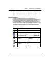
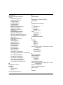
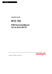
Lucent Technologies User’s Guide CAJUN M770 MANAGER CAJUNVIEW NETWORK MANAGEMENT August 1999 Contents List of Figures ........................................................................................... v List of Tables........................................................................................... vii Chapter 1 Welcome to Cajun M770 Management ................................................... 1 The Purpose of this Manual ..................................................................... 1 Who Should Use This Manual ................................................................. 1 Organization of this Manual .................................................................... 1 Starting Cajun M770 Management.......................................................... 2 What To Do First ............................................................................ 2 Running Cajun M770 Management from Windows ..................... 2 Running Cajun M770 Management from UNIX ........................... 2 Using Chassis View................................................................................... 4 Launching Module Managers ........................................................ 4 Selecting Elements ......................................................................... 5 Using the Toolbar Buttons ............................................................. 5 Using Configuration Windows ................................................................. 6 Chapter 2 Agent Configuration ................................................................................ 7 General Agent Installation and Configuration ......................................... 7 Verifying Agent Installation ........................................................... 7 Downloading New Agent Software ............................................... 7 Viewing the Agent Information Window ...................................... 7 Designating Managers .............................................................................. 8 Viewing the Managers Table .......................................................... 8 Adding Managers to the Managers Table ...................................... 9 Removing Managers from the Managers Table ............................. 9 Updating the Managers Table ...................................................... 10 Chapter 3 Device Configuration ............................................................................. 11 Viewing Device Information .................................................................. 12 Viewing Hardware Configuration .......................................................... 13 Viewing Module Configuration ............................................................. 14 Viewing Port Configuration ................................................................... 15 Enabling Ports .............................................................................. 16 Disabling Ports ............................................................................. 16 Viewing Domain Resource Unit Information ........................................ 17 Viewing ATM Clock Synchronization Configuration............................. 18 Cajun M770 Manager User’s Guide i Resetting Elements ................................................................................. 19 Resetting the Device .....................................................................19 Resetting the Agent ......................................................................19 Resetting the Switch ....................................................................19 Resetting the Module ...................................................................19 ii Chapter 4 Fault Management ................................................................................. 21 Configuring Traps................................................................................... 21 Viewing Traps......................................................................................... 22 Viewing Traps in a Dialog Box .....................................................22 Viewing Traps in the Event Log ...................................................22 Assigning Severity Degrees in UNIX ...................................................... 22 Accessing Severity Degrees ..........................................................22 Editing Severity Degrees ..............................................................23 Chapter 5 Performance Monitoring ........................................................................ 25 Viewing Ethernet Port Counters ............................................................ 26 Viewing Ethernet Port Error Counters................................................... 27 Chapter 6 Port Mirroring ........................................................................................ Accessing Port Mirroring ........................................................................ Enabling Port Mirroring ......................................................................... Disabling Port Mirroring......................................................................... 29 30 31 31 Chapter 7 Port Redundancy.................................................................................... Viewing Port Redundancy Information ................................................. Adding a Port Redundancy .................................................................... Editing a Port Redundancy..................................................................... Deleting a Port Redundancy................................................................... 33 33 34 34 34 Chapter 8 Switch Connected Addresses.................................................................. 35 Sorting the List of Stations ..................................................................... 36 Saving the List of Stations ...................................................................... 36 Chapter 9 VLANs .................................................................................................... 37 Creating and Editing VLANs................................................................... 37 Accessing the VLAN List ...............................................................38 Editing VLAN Names and Numbers .............................................38 Editing VLAN Member Ports ........................................................39 Allowing Inter-VLAN Communication .................................................. 40 Cajun M770 Manager User’s Guide Appendix A Cajun M770 Management Menus ......................................................... Configuration ........................................................................................ Performance ........................................................................................... Administer.............................................................................................. Help ........................................................................................................ 41 41 42 42 43 Appendix B Configuration Fields............................................................................... 45 Appendix C Counter Fields ........................................................................................ 55 Appendix D Trap Fields .............................................................................................. 57 Index ...................................................................................................... 59 Cajun M770 Manager User’s Guide iii iv Cajun M770 Manager User’s Guide List of Figures Figure 1.1 Figure 1.2 Figure 2.1 Figure 2.2 Figure 3.1 Figure 3.2 Figure 3.3 Figure 3.4 Figure 3.5 Figure 3.6 Figure 4.1 Figure 5.1 Figure 5.2 Figure 6.1 Figure 7.1 Figure 8.1 Figure 9.1 Cajun M770 Manager User’s Guide Chassis View ......................................................................... 4 Chassis View Toolbar ............................................................ 5 Agent Information Window ................................................. 8 Managers Table..................................................................... 9 Device Information Dialog Box .......................................... 12 Hub Hardware Window...................................................... 13 Module Configuration Window ......................................... 14 Port Configuration Dialog Box ........................................... 15 DRUs Information Window ................................................ 17 Clock Synchronization Dialog Box ..................................... 18 Traps Configuration Dialog Box ......................................... 21 Ethernet Port Counters Window ........................................ 26 Port Error Counters Window.............................................. 27 Port Mirroring Dialog Box .................................................. 30 Port Redundancy Dialog Box.............................................. 33 Switch Connected Addresses for Device Window .............. 35 Virtual LANs for Device Dialog Box ................................... 38 v List of Figures vi Cajun M770 Manager User’s Guide List of Tables Table 1.1 Table A.1 Table A.2 Table A.3 Table A.4 Cajun M770 Manager User’s Guide Chassis View Toolbar ............................................................ 5 Configuration Menu ........................................................... 41 Performance Menu ............................................................. 42 Administer Menu................................................................ 42 Help Menu .......................................................................... 43 List of Tables viii Cajun M770 Manager User’s Guide Chapter 1 Welcome to Cajun M770 Management Welcome to Cajun M770 Management. This chapter provides an introduction to the structure and assumptions of the manual. It includes the following sections: • The Purpose and Readers of this manual - A description of the goals of this manual and its intended audience. • Organization of the manual - A brief description of the subjects contained in the various sections of the manual. • Starting Cajun M770 Management - Instructions on how to access Cajun M770 Management from your management platform. • Using Chassis View - A brief introduction to the Cajun M770 Chassis View, including instructions on how to select elements and use the toolbar buttons. The Purpose of this Manual The Cajun M770 Manager manual contains the information needed to use the management system efficiently and effectively. Who Should Use This Manual This manual is intended for network managers familiar with network management and its fundamental concepts. Organization of this Manual This manual is structured to reflect the following conceptual divisions: • Welcome to Cajun M770 Management - This section describes the manual’s purpose, intended audience and organization. • Agent Configuration - Viewing and modifying the agent configuration. • Device Configuration - Viewing and modifying the different device configurations. • Managers Configuration - Selecting managers to receive network traps. • Fault Management - Selecting the traps to be sent by the network unit to the managers. • Performance Monitoring - Viewing performance statistics for the ports in a Cajun M770 Multifunction Device. • Port Mirroring - Configuring port mirroring on a Cajun M770 Mutifunction Device. Cajun M770 Manager User’s Guide 1 Chapter 1 Welcome to Cajun M770 Management Port Redundancy - Setting port redundancy for ports in a Cajun M770 Multifunction Device. Switch Connected Addresses - Viewing users and devices connected to selected ports. VLANs - Creating, viewing, and modifying VLANs. Management Menus - The full menu structure of the menus in Cajun M770 Device management. Configuration Fields - All configuration fields referenced and their descriptions. Counter Fields - All counter fields referenced and their descriptions. Trap Fields - All trap fields and their descriptions. Starting Cajun M770 Management This section provides instructions for starting Cajun M770 Management from the various supported management umbrellas. What To Do First To begin: 1 Login to the system using your account name. 2 Ensure that the management platform system is running correctly. Running Cajun M770 Management from Windows To start Cajun M770 Management from HP OpenView: 1 Double-click the icon representing the Cajun M770 Multifunction Device you want to work with. OR Select a Cajun M770 Multifunction Device, open the Lucent menu and select Device Manager. Running Cajun M770 Management from UNIX If you are using NetView/6000: 1 From the Management platform map, select the Cajun M770 Multifunction Device you wish to work with. 2 Open the Tools menu and select Lucent Device Manager. OR 1 Right-click on the Cajun M770 Multifunction Device you wish to work with. 2 Select Lucent: Device Manager. 2 Cajun M770 Manager Users Guide Chapter 1 Welcome to Cajun M770 Management If you are using OpenView (Solaris or HPUX) or NT-OV: 1 From the management platform map, select the Cajun M770 Multifunction Device you wish to work with. 2 Click in the OpenView toolbar. OR Open the Tools menu and select Lucent Device Manager. OR Right-click on the Device you want, and Select Lucent: Device Manager. Cajun M770 Manager User’s Guide 3 Chapter 1 Welcome to Cajun M770 Management Using Chassis View The Cajun M770 Chassis View is a graphical representation of a Cajun M770 Device which displays all modules installed in the chassis. This includes both Cajun M400 modules, DomainX modules, ATM modules, and M-MLS modules. Legacy modules are only displayed in the Chassis View if there is an NMA-Rx agent mounted in the Cajun M770. The NMA-Rx agent should be mounted in the rightmost slot (#14) of the Cajun M770. The 6U legacy modules are displayed in the Chassis View with padding to the width and height of the new 12U modules. Figure 1.1 Chassis View Launching Module Managers The Cajun M770 Manager enables you to launch the manager of a legacy module, an ATM module, or router module from the Chassis View. To launch the manager of one of these modules: 1 Select the module. 2 Click . OR Open the Administer menu and select Launch Device Manager. The requested manager application is launched. 4 Cajun M770 Manager User’s Guide Chapter 1 Welcome to Cajun M770 Management Selecting Elements Within the Chassis View, you can select modules and ports. To select an element, click on it using the left mouse button. The selected element is highlighted. To select multiple elements, press the CTRL key while clicking on each element to be selected. Using the Toolbar Buttons The Toolbar provides shortcuts to the main Chassis View functions. In a Windows environment the toolbar may be displayed as a floating horizontal toolbar or as a docked, vertical toolbar. To display the toolbar, open the Administer menu and select ToolBar. A check is placed next to the Toolbar option when it is activated. To dock the toolbar, drag it to the right edge of the Chassis View. To hide the toolbar, open the Administer menu and select ToolBar. The table below describes the buttons on the Toolbar and gives the equivalent menu options. Table 1.1 Icon Chassis View Toolbar Description Menu Item Exit the application. Configuration View general device information. Configuration Device Information... View the managers table. Configuration View device hardware information. Configuration Hardware... View device agent information. Configuration Agent... View clock synchronization information. Configuration Launch manager. Administer Launch Device Manager... Cajun M770 Manager User’s Guide Exit Zoom Managers Table... Device Element ATM Clock Sync... 5 Chapter 1 Welcome to Cajun M770 Management Table 1.1 Icon Chassis View Toolbar (Continued) Description Menu Item VLANs. A VLAN can be selected. All ports not associated with that VLAN are dimmed in the Chassis View. Open on-line Help. Help Contents When you place the cursor on the toolbar icon for 1 second, a label appears with the name of the button. Using Configuration Windows When using the configuration windows: • Click OK to upload information (if applicable) from the window to the appropriate agent, module, or port. • Click Cancel to close the active window. 6 Cajun M770 Manager User’s Guide Chapter 2 Agent Configuration Before your network or Cajun M770 will work properly, your network agents must be properly configured. This chapter helps you properly setup and configure your agents, and includes helpful configuration notes for the different agent types. The following sections are included: • General Agent Installation and Configuration - General information on agent configuration. • Designating Managers - Assigning management stations for managing the Cajun M770 Device. General Agent Installation and Configuration The following topics describe how to set up and configure all Lucent Technologies agents. Verifying Agent Installation Before configuring your agents, make sure that each has been properly installed. Check that the agent has been properly connected to the device, and the IP address and community name for the agent have been set as described in the agent's Installation Guide. Downloading New Agent Software Downloading agent software is done using the Cajun Download Manager. For instructions, please refer to the on-line help for the Cajun Download Manager, or the Cajun Download Manager User’s Guide included in the Additional Applications User’s Guide. Viewing the Agent Information Window Every Lucent Technologies agent has an Agent Information window which provides you with details about the agent. To view the configuration of an agent: 1 Click . OR Open the Configuration menu and select Element Agent. The Agent Information window appears. Cajun M770 Manager User’s Guide 5 Chapter 2 Agent Configuration Figure 2.1 Agent Information Window The Agent Information window provides information about the main and backup agents, such as their type, position, software version, and operational status. For a full description of all configuration fields in the Agent Information window, refer to Appendix B, Configuration Fields. Designating Managers Agents send alarms to Managers’ workstations that are on the agent's Manager list. Alarms will not be sent out to any other network management stations (NMS). If you want to properly manage a device, your station should be one of its designated Managers. The Manager can be a Cajun M770 Management station or any other SNMP (Simple Network Management Protocol) management console. Note: It is recommended to keep the list limited to actual and relevant managers so as not to place undue stress on the network. Note: Refer to the Cajun M770 Installation Guide for an out-of-band method for editing a device's Manager list. Viewing the Managers Table To view the list of Managers: 1 Click on the toolbar. OR 6 Cajun M770 Manager User’s Guide Chapter 2 Agent Configuration Open the Configuration menu and select Managers Table. The Managers Table dialog box appears. Figure 2.2 Managers Table The dialog box lists the IP addresses, node names of the Managers, and their trap reporting status. Adding Managers to the Managers Table To add managers to the list: 1 Click on the IP address field and enter the IP address of the designated management station. When the change takes effect, the management station’s name will be displayed automatically in the Device Name column. 2 Repeat the procedure for each manager. 3 Click OK. The change takes effect immediately. Note: The indicated manager will receive traps only when Trap Reports for that manager is enabled. Removing Managers from the Managers Table To remove managers from the list: 1 Click on the IP address field and enter 0.0.0.0. 2 Repeat the procedure for each manager. 3 Click OK. The change takes effect immediately. Cajun M770 Manager User’s Guide 7 Chapter 2 Agent Configuration Updating the Managers Table To edit the managers list: 1 Click on the IP address field and change the IP address of the designated management station. When the change takes effect, the management station’s name will be displayed automatically in the Device Name column. 2 Repeat the procedure for each manager. 3 Click OK. The change takes effect immediately. To close the Managers Table dialog box, click Cancel. 8 Cajun M770 Manager User’s Guide Chapter 3 Device Configuration This chapter explains how to view and set the various configuration parameters relevant to devices on your network. It includes the following sections: • Viewing Device Information - View device information about the Cajun M770 Device. • Viewing Hardware Configuration - View power supply parameters of the Cajun M770 Device. • Viewing Module Configuration - View information for the Cajun M770 modules. • Viewing Port Configuration - View information specific to the ports of the Cajun M770 modules. • Viewing Domain Information - View information about the DRUs in the DomainXs of the Cajun M770 Device. • Viewing ATM Clock Synchronization Configuration - View clock synchronization parameters for the Cajun M770 Device. • Resetting Elements - Reset various elements of the Cajun M770 Device. Note: To view agent configuration, refer to Chapter 2, Agent Configuration. Cajun M770 Manager User’s Guide 9 Chapter 3 Device Configuration Viewing Device Information The Device Information dialog box provides high-level information specific to the selected Cajun M770 Device. To view the Device Information dialog box: 1 Click . OR Open the Configuration menu and select Device Information. The Device Information dialog box appears. Figure 3.1 Device Information Dialog Box The Device Information dialog box provides detailed information about the device such as the system name, description, contact, and location, the device type, its MAC address, and any faults that may have occurred on the device. To apply any changes made to the information in the Device Information dialog box, click OK. To close the Device Information dialog box, click Cancel. For a full description of all fields in the Device Information dialog box, refer to Appendix B, Configuration Fields. 10 Cajun M770 Manager User’s Guide Chapter 3 Device Configuration Viewing Hardware Configuration The Hub Hardware window provides information about the presence and status of Power Supply Units (PSUs) and fans. To view hardware parameters from Chassis View: 1 Click . OR Open the Configuration menu and select Device Hardware. The Hub Hardware window appears. Figure 3.2 Hub Hardware Window The Hub Hardware window shows the location, type, HW version, and status of the Power Supply Units (PSUs), and the status of the cooling fans. For a full description of all configuration fields in the Hardware Information window, refer to Appendix B, Configuration Fields. Cajun M770 Manager User’s Guide 11 Chapter 3 Device Configuration Viewing Module Configuration The Device Configuration window provides you with information specific to a selected module. To view the configuration of a Cajun M770 module: 1 Select a module by clicking on its label. 2 Open the Configuration menu and select Element Module. OR Double-click on the module label. The Module Configuration window appears. Figure 3.3 Module Configuration Window The Module Configuration dialog box provides detailed information about the module such as the module type, its position in the device, number of ports, the version of its software, and its DRU usage. To apply any changes made to the information in the Module Configuration dialog box, click OK. To close the Module Configuration dialog box, click Cancel. For a full description of all configuration fields in the Module Configuration dialog box, refer to Appendix B, Configuration Fields. 12 Cajun M770 Manager User’s Guide Chapter 3 Device Configuration Viewing Port Configuration The Port Configuration dialog box provides you with information specific to a selected port. To view the configuration of a port: 1 Select a port by clicking on it. 2 Open the Configuration menu and select Element Port. OR Double-click on a port symbol. OR Right-click on a port and select Port Configuration. The Port Configuration dialog box appears. Figure 3.4 Port Configuration Dialog Box The Port Configuration dialog box provides detailed information about the port, such as the port type, its status, mode of operation, classification, and any faults with the port. The information fields in Port Configuration dialog box may vary according to the type of port selected. For a full description of all configuration fields in the Port Configuration dialog box, refer to Appendix B, Configuration Fields. Cajun M770 Manager User’s Guide 13 Chapter 3 Device Configuration Enabling Ports To enable a port: 1 Select the port in the Chassis View. 2 Open the Configuration menu and select Enable Port. A confirmation box appears. 3 Click Yes. The port is enabled. OR 1 Right-click on the port and select Enable Port. A confirmation box appears. 2 Click Yes. The port is enabled. OR 1 Open the Port Configuration dialog box. 2 Change the Administration Status to enabled. 3 Click OK to apply the change. The port is enabled. To enable more than one port: 1 Select multiple ports by holding down the CTRL key as you click on the ports. 2 Open the Configuration menu and select Enable Port. A confirmation box appears. 3 Click Yes. The selected ports are enabled. Disabling Ports To disable a port: 1 Select the port in the Chassis View. 2 Open the Configuration menu and select Disable Port. A confirmation box appears. 3 Click Yes. The port is disabled. OR 1 Right-click on the port and select Disable Port. A confirmation box appears. 2 Click Yes. The port is disabled. OR 1 Open the Port Configuration dialog box. 2 Change the Administration Status to disabled. 3 Click OK to apply the change. The port is disabled. To disable more than one port: 1 Select multiple ports by holding down the CTRL key as you click on the ports. 2 Open the Configuration menu and select Disable Port. A confirmation box appears. 3 Click Yes. The selected ports are disabled. 14 Cajun M770 Manager User’s Guide Chapter 3 Device Configuration Viewing Domain Resource Unit Information Each DomainX in the Cajun M770 Device has a total of 100 available DRUs. The DRUs Information window provides DRU usage information for each DomainX. To view the DRUs Information window: 1 Open the Configuration menu and choose DRUs. The DRU Information window appears. Figure 3.5 DRUs Information Window The DRUs Information window provides DRU information separately for the left and right DomainX. This information includes the type, slot numbers, and DRU information for each module in the device, and the total number of DRUs in use. For a full description of all configuration fields in the DRUs Information window, refer to Appendix B, Configuration Fields. Cajun M770 Manager User’s Guide 15 Chapter 3 Device Configuration Viewing ATM Clock Synchronization Configuration Some multimedia applications, such as voice, require that a single clock is propagated throughout the network. The clock source is usually a Public Telco switch connected to a local PBX through a telephony network. Using the Cajun M770 ATM Device, up to four external references can be configured, two from ATM ports and two from external E1/T1 sources. These are all directed to the M-SPS module which selects one of them to be the source input timing device. It uses the selected source to generate a 19.44MHz clock which is distributed to all modules. This is used by all ATM ports to synchronize Sonet frames. The ATM Clock Synchronization dialog box provides information about the method currently configured for synchronizing the clocks in the Cajun M770 Device. To view and edit clock synchronization parameters from Chassis View: 1 Click . OR Open the Configuration menu and select ATM Clock Sync. The ATM Clock Synchronization dialog box appears. Figure 3.6 Clock Synchronization Dialog Box The ATM Clock Synchronization dialog box shows the module type, status, and current source of clock synchronization. It also provides a table of clock synchronization parameters for all the clock sources, and allows you to edit their configurations. To edit the configuration of a clock synchronization source: 1 Select one of the sources from the table. 2 Modify the parameters in the Row Configuration area of the dialog box. 3 Click OK. The configuration of the clock source is modified. 16 Cajun M770 Manager User’s Guide Chapter 3 Device Configuration Note: When configuring the ATM source port, ensure that the ATM module/port can be used as a clock synchronization source. Suitable modules/ports are: Ports 1 and 2 on M15-155 modules with C/S 2.0 or higher. All ports on M3-622 modules with C/S 1.0 or higher. For a full description of all configuration fields in the ATM Clock Synchronization dialog box, refer to Appendix B, Configuration Fields. Cajun M770 Manager User’s Guide 17 Chapter 3 Device Configuration Resetting Elements You can reset the entire Cajun M770 Device or various elements of the device without resetting the entire device. Resetting the Device To reset the entire device with all its modules and subsystems: 1 Open the Configuration menu and select Reset Device. The entire device is reset. Resetting the Agent To reset the M-SPV/M-SPX/M-SPS agent of the device: 1 Open the Configuration menu and select Reset Agent. The M-SPV/M-SPX/M-SPS agent CPU is reset. No other modules in the device are affected. Resetting the Switch To reset the agent and modules in the left DomainX: 1 Open the Configuration menu and select Reset DomainX DomainXL. To reset the agent and modules in the right DomainX: 1 Open the Configuration menu and select Reset DomainX DomainXR. Only the selected DomainX is reset. Resetting the Module To reset an individual module: 1 Select a module. 2 Open the Configuration menu and select Reset module is reset. 18 Module. Only the selected Cajun M770 Manager User’s Guide Chapter 4 Fault Management This chapter explains how to configure and view traps on your network. It includes the following sections: • Configuring Traps - Defining the types of traps that will be sent to the managers and alarm log. • Viewing Traps - Viewing the traps sent by the agent. In UNIX and Windows NT: • Severity Degrees - Defining, accessing and understanding severity degrees. Configuring Traps A trap is an SNMP message sent by the agent to its managers. Trap messages may appear in the Configuration Windows of the port or module affected, in addition to being sent to the management stations listed in the Manager’s Table. You can set the types of traps the unit will forward to the management station you are configuring. To configure traps: 1 Open the Configuration menu and select Traps. The Traps Configuration dialog box appears. Figure 4.1 2 3 Traps Configuration Dialog Box Enable the types of traps you want forwarded to the management station you are configuring. Click OK to apply any changes. To close the Traps Configuration dialog box, click Cancel. Cajun M770 Manager User’s Guide 19 Chapter 4 Fault Management For a full description of all traps in the Traps Configuration dialog box, refer to Appendix D, Trap Fields. Viewing Traps Traps that are sent by the agent to its managers may be viewed in two places: • In the appropriate configuration dialog box. • In the event log. Viewing Traps in a Dialog Box A list of traps sent by the agent is maintained by the management application. The list can be viewed in a dropdown list box in the Device Information, Module Configuration, and Port Configuration dialog boxes. Viewing Traps in the Event Log HP OpenView maintains a list of all traps sent by the agents on the network. They may be viewed by opening the Event Log from the HP OpenView network map window. For a full description of the Event Log, refer to the HP OpenView Administrator’s Guide. Assigning Severity Degrees (UNIX and NT-OV Only) Management applications, using the Event Configuration application, allow you to set fault severity degrees system-wide, (for all devices on the network simultaneously), or for specific devices (per IP). If the system-wide setting and an individual device’s setting disagree, the individual device’s setting takes precedence. For more information refer to Severity Degrees in The Reference Guide. Accessing Severity Degrees Only events whose category is “Status Events” affect the device’s status. Events in this category may be found under the enterprises Lannet (.1.3.6.1.4.1.81) and CajunM770 (.1.3.6.1.4.1.81.17.1.15). Severity degree settings may be accessed from the Event Configuration application. To open the Event Configuration application: 1 From the umbrella management application, open the Tools menu and select Lucent Event Configuration. OR Open the Options menu and select Event Configuration. The Event Configuration application appears. 20 Cajun M770 Manager User’s Guide Chapter 4 Fault Management Editing Severity Degrees Severity degrees may be changed for faults on a system-wide basis, or for specific devices (per IP). Caution: Do not change the Event Object Identifier of a fault. Editing Severity Degrees System-Wide To edit severity degree settings system-wide: 1 Select the enterprise which contains the fault whose settings you want to edit. A list of the faults under the enterprise appears in the Event Identification window. 2 Select the fault whose settings you want to edit. 3 Open the Edit menu and select Modify Event. OR Double-click the fault whose settings you want to edit. The Event Configurator window appears. 4 Change the severity setting using the Severity pull-down list. 5 Click OK. 6 Save the changes. — In HP OpenView and NT-OV: Select File Save. — In NetView: Click Apply. Editing Severity Degrees for Specific Devices To edit severity degree settings for specific devices: 1 Select the enterprise which contains the fault whose settings you want to edit. A list of the faults under the enterprise appear in the Event Identification window. 2 Select the fault whose settings you want to edit. 3 Copy the fault by opening the Edit menu and selecting Copy Event. The Event Configurator window appears. 4 Enter a name for the fault in the Event Name field. 5 Set Source to the IP address/es of the specific device/s you want the changes to be effective on. 6 Change the severity setting using the Severity pull-down list. 7 Click OK. 8 Save the changes. — In HP OpenView and NT-OV: Select File Save. — In NetView: Click Apply. Cajun M770 Manager User’s Guide 21 Chapter 4 Fault Management Note: All changes to the severity degrees will only take effect after the changes are saved. Refer to the HPOV Event Configuration application help for more information. 22 Cajun M770 Manager User’s Guide Chapter 5 Performance Monitoring This chapter explains the performance monitoring options of supported devices. It includes the following sections: • Viewing Ethernet Port Counters - Provides a breakdown of the packets going through each port. • Viewing Ethernet Error Port Counters - Displays different Ethernet Error counters for the Cajun M770 ports. Cajun M770 Manager User’s Guide 23 Chapter 5 Performance Monitoring Viewing Ethernet Port Counters Port Counters allow you to accurately view the packet flow activity of each port in the . Once you learn what is normal packet activity for your network, Ethernet Port Counters will help you determine network malfunctions, bottlenecks and overloaded ports. To view Ethernet Port Counters from Chassis View: 1 Select a port or ports to be monitored. — To select a single port, click on the port’s symbol. — To select multiple ports, hold the CTRL key as you click on additional ports. — To select all Ethernet ports of a DomainX module, click on the module’s symbol. 2 Open the Performance menu and select Port Counters. The Ethernet Port Counters window appears. Figure 5.1 Ethernet Port Counters Window Ethernet Counters are gathered for each selected port. The display is updated automatically every thirty seconds. To manually update the display, click Start. Click Clear Counters to reset all the counter values to 0. The exact time you click this button will be entered in the Counters Cleared At field. When you click Clear Counters the counters are not reset on the agent. To close the Ethernet Port Counters dialog box, click Cancel. For a full description of all Ethernet port counters, refer to Appendix C, Counter Fields. 24 Cajun M770 Manager User’s Guide Chapter 5 Performance Monitoring Viewing Ethernet Port Error Counters As part of a proactive fault management system, or if you suspect that something is wrong, you may want to monitor port error counters. To view Ethernet Port Error Counters from Chassis View: 1 Select a port or ports to be monitored. — To select a single port, click on the port’s symbol. — To select multiple ports, hold the CTRL key as you click on additional ports. — To select all Ethernet ports of a DomainX module, click on the module’s symbol. 2 Open the Performance menu and select Port Error Counters. The Port Error Counters window appears. Figure 5.2 Port Error Counters Window Port Error Counters are gathered for each selected port. The display is updated automatically every thirty seconds. To manually update the display, click Start. Click Clear Counters to reset all the counter values to 0. The exact time you click this button will be entered in the Counters Cleared At field. When you click Clear Counters the counters are not reset on the agent. To close the Port Error Counters dialog box, click Cancel. For a full description of all Ethernet Port Error Counters, refer to Appendix C, Counter Fields. Cajun M770 Manager User’s Guide 25 Chapter 5 26 Performance Monitoring Cajun M770 Manager User’s Guide Chapter 6 Port Mirroring Port Mirroring copies all received and transmitted packets (including local traffic) from a source port to a predefined destination port, in addition to the normal destination port of the packets. The source and destination ports must be located in the same DomainX. For more information, refer to Port Mirroring in The Reference Guide. This section explains how to configure a device’s ports to use Port Mirroring, and includes: • Accessing Port Mirroring - Describes how to access the Port Mirroring dialog box. • Enabling Port Mirroring - Describes how to enable and define source and destination modules and ports. • Disabling Port Mirroring - Describes how to disable port mirrors. Note: Port Mirroring is not permitted when there is no link on the destination port. Caution: Do not change the VLAN of the source or destination port while the port mirroring mechanism is operating. Cajun M770 Manager User’s Guide 27 Chapter 6 Port Mirroring Accessing Port Mirroring To open the Port Mirroring dialog box for a DomainX: 1 Open the Configuration menu, and select Port Mirroring left DomainX. OR Open the Configuration menu, and select Port Mirroring right DomainX. The Port Mirroring dialog box appears. DomainXL for the DomainXR for the Note: When none of the ports in the switch support Port Mirroring, the Port Mirroring option in the Configuration menu is inactive. Figure 6.1 Port Mirroring Dialog Box The Port Mirroring dialog box displays configuration options for setting source and destination ports, current source and destination ports, and the Port Mirroring status. For a full description of all configuration fields in the Port Mirroring dialog box, refer to Appendix B, Configuration Fields. 28 Cajun M770 Manager User’s Guide Chapter 6 Port Mirroring Enabling Port Mirroring To enable port mirroring, you must define a source and destination port. Note: Only a single pair of ports can be defined for port mirroring on each DomainX. To enable Port Mirroring for the DomainX: 1 In the Port Mirroring dialog box, open the Port Monitoring drop-down list (refer to Figure 6.1) and select Enable. 2 Define source and destination ports in one of the following ways: a From the Module drop-down list, select a module number and a port number. OR a b 3 In the Chassis View click on the port you want to set. In the Port Mirroring dialog box, click Select from Zoom. The port and module numbers appear in the Port Mirroring dialog box (refer to Figure 6.1). Click OK. The manager sets the source and the destination ports for copying packets, enabling Port Mirroring. Disabling Port Mirroring To disable Port Mirroring: 1 In the Port Mirroring dialog box, open the Port Monitoring drop-down list (refer to Figure 6.1) and select Disable. 2 Click OK. Received and transmitted packets are not copied from one port to another. To close the Port Mirroring dialog box, click Cancel. Cajun M770 Manager User’s Guide 29 Chapter 6 30 Port Mirroring Cajun M770 Manager User’s Guide Chapter 7 Port Redundancy Port Redundancy enables you to define a redundancy relationship between any two ports in a device. One port is defined as the primary port and the other as the secondary port. In case the primary port fails, the secondary port will take over. This connection between the two ports is called a Port Redundancy. For more information refer to Redundancy in The Reference Guide. Viewing Port Redundancy Information To access Port Redundancy: 1 Open the Configuration menu and select Software Redundancy. The Port Redundancy dialog box appears. Figure 7.1 Port Redundancy Dialog Box The Port Redundancy dialog box provides a list of all port redundancies established on the device, with their respective primary and secondary ports. Cajun M770 Manager User’s Guide 31 Chapter 7 Port Redundancy Adding a Port Redundancy To designate a port redundancy connection: 1 In the Port Redundancy dialog box, enter a name for the redundancy in the Redundancy Name field. For example, Redund1. Note: The name for a redundancy may not contain any spaces. 2 3 4 Select a primary port from the Primary field. Select a secondary port from the Secondary field. Click Add. The new port redundancy is added to the list of existing port redundancies. To close the Port Redundancy dialog box, click Cancel. Note: Ports that have already been designated in one redundancy scheme, may not be selected for another one. Editing a Port Redundancy To edit an existing redundancy connection: 1 In the Port Redundancy dialog box, click on the redundancy connection you wish to edit. The connection information appears in the boxes at the bottom of the Port Redundancy window. 2 Change the information as desired. 3 Click Update. The current port redundancy in the list is updated according to the modifications made. Deleting a Port Redundancy To delete a port redundancy connection: 1 In the Port Redundancy dialog box, click on the redundancy connection you wish to delete. 2 Click Delete. The port redundancy is deleted from the list. 32 Cajun M770 Manager User’s Guide Chapter 8 Switch Connected Addresses Networks are becoming increasingly complicated entities. It is not always clear which users are connected to the network and how. The Switch Connected Addresses feature allows you to see which users and devices are connected to selected ports or modules. Keeping track of this information in the network can increase efficiency, security and confidentiality. Switch Connected Addresses provides a list of all selected ports along with the names (IP address or host name), if available, and MAC addresses of the elements connected to them. To view the connected stations: 1 Open the Configuration menu and select Switch Connected Addresses. The Switch Connected Addresses for Device window appears. Figure 8.1 Switch Connected Addresses for Device Window The rows of the Switch Connected Addresses window comprise the following information: • Module - The number of the module and the module type. • Port/Bank - The number of the port in the module. • List of stations connected to port - When a port is selected, the stations connected to the port are listed. These stations can be sorted by the MAC address or host name, or they can be left unsorted. Cajun M770 Manager User’s Guide 33 Chapter 8 Switch Connected Addresses Sorting the List of Stations To sort the list of stations, open the drop-down list in the Sort Method field and select a field. The list is immediately sorted upon selection of a sort field. Saving the List of Stations The list of stations connected to the port may be saved as a text file by clicking the Save As button. The Save As dialog box will open and prompt you for the directory and file name you wish to save the list to. This list can then be referenced in the future using any text editor. 34 Cajun M770 Manager User’s Guide Chapter 9 VLANs This chapter provides all the information and instructions you need to use virtual LANs. It includes the following sections: • Creating and Editing VLANs - Explains how to access and edit the VLAN list. • Allowing Inter-VLAN Communication - Explains how you can allow selected users to have access to all the VLANs. For more information about VLANs, refer to VLANs in The Reference Guide. Creating and Editing VLANs The building blocks of VLANs are switch ports. To build a new VLAN you need to select a VLAN name and number and then decide which switch ports will be members of the VLAN. The default VLAN on the Cajun M770 Device can be set to VLAN 0 (Generic) or VLAN 1 (Default) using the command line interface. For more information, refer to The Cajun M770 User’s Guide. You can change the VLAN configuration on a per port basis. In order to be compliant with the IEEE 802.1Q VLAN standard, you have to modify ports with VLAN 0 to another VLAN. Cajun M770 Manager User’s Guide 35 Chapter 9 VLANs Accessing the VLAN List To create or edit VLAN names, numbers or component switch ports you need to access the VLAN list: 1 Open the Configuration menu and select Virtual LANs. The Virtual LANs for Device dialog box appears. Figure 9.1 Virtual LANs for Device Dialog Box The left column of the Virtual LANs for Device dialog box lists all VLAN names and numbers. Click on a name to select a VLAN. The right column lists member switch ports of the currently selected VLAN. Editing VLAN Names and Numbers To add to the list of VLANs: 1 Click on the LAN # box and enter a number between 1 and 254 that does not already exist in the Virtual LAN list. 2 Click on the LAN Name box and enter a VLAN name. Any name can be used. 3 Click Add VLAN. The new VLAN will be added to the All Virtual LANs list. To delete from the list of Virtual LANs: 1 Select the VLAN you wish to delete. 2 Click Delete VLAN. The VLAN disappears from the list. If there were any elements left on the Assigned Members list you will be asked for confirmation and those elements will be deleted from the VLAN and placed in the default VLAN. 36 Cajun M770 Manager User’s Guide Chapter 9 VLANs Editing VLAN Member Ports To assign ports to VLANs: 1 Arrange the windows so you can see the Virtual LANs for Device dialog box and the Chassis View at the same time. 2 From the All Virtual LANs List, select the VLAN you wish to edit. 3 In the Chassis View, click on the ports you wish to add to the VLAN (use CTRLclick to select multiple ports). By selecting a DomainX module (use CTRL-click to select multiple modules), you select all ports contained within those elements. 4 Click Add Zoom Sel in the Virtual LANs for Device dialog box. The selected switch ports are assigned to the selected VLAN and automatically deleted from any other VLAN. Note: To view the ports associated with a specific VLAN, choose the VLAN from the VLAN dropdown listbox on the Zoom View toolbar. The active ports associated with the chosen VLAN will remain highlighted. All other ports will be dimmed. To disassociate switch ports from VLANs: 1 From the Virtual LANs for Device dialog box, select the VLAN you wish to edit from the All Virtual LANs list. 2 On the Assigned Members list, locate and click on the switch port you wish to delete. 3 Click Remove. The port is removed from the list and automatically reassigned to the default VLAN. Repeat this procedure for every port you wish to remove from the VLAN. Cajun M770 Manager User’s Guide 37 Chapter 9 VLANs Allowing Inter-VLAN Communication Individual switch ports may be given the status of “Global Port”. Global ports can communicate with all VLANs. This feature has many uses: • Executives or administrators in a company can give their switch ports Global port status so they can access all VLANs. • A server attached to a Global port can serve many VLANs. • Indirect communication between VLANs can be arranged. Via a server attached to the Global port, packets (mail, for example) may be transferred to any VLAN. To give the status of Global Port to a switch port: 1 From the Chassis View, open the Configuration menu and select Virtual LANs. 2 Arrange the windows so you can see the Virtual LANs for Device dialog box and the Chassis View at the same time. 3 From the Virtual LANs list, select Global (# 255). 4 In the Chassis View, select the switch port you want to set to Global Port status (use CTRL-click to select multiple switch ports). 5 Click Add Zoom Sel. The selected switch parts are assigned to Global and automatically deleted from any other VLAN. 38 Cajun M770 Manager User’s Guide AppendixA Cajun M770 Management Menus This appendix gives the full menu structure of the menus in the Cajun M770 management application. Configuration Table A.1 Configuration Menu Item Description Device Information Displays information about the device. Agent Element Module Element Element Port Displays configuration information for an agent. Displays configuration information for a module. Displays configuration information for a port. Enable Ports Enables the selected port/s. Disable Ports Disables the selected port/s. Traps Displays trap configuration information. Managers Table Displays managers configuration information. Software Redundancy Displays and enables configuration of software redundancies. Device Hardware Displays the device hardware information. Port Mirroring DomainXL Port Mirroring DomainXR Displays and enables configuration of port mirroring on the left DomainX. Displays and enables configuration of port mirroring on the right DomainX. Virtual LANs Displays and enables configuration of virtual LANs. Switch Connected Addresses Displays a list of stations connected to each of the device’s ports. Cajun M770 Manager User’s Guide 39 Table A.1 Configuration Menu (Continued) Item Description DRUs Displays Domain Resource Unit usage for the right and left DomainX. ATM Clock Sync Displays clock synchronization information. Reset Device Resets the entire hub with all its modules and subsystems. Agent Reset DomainX Reset Resets the M-SPV agent CPU only. Resets the left DomainX. DomainXL Reset DomainX DomainXR Reset Module Exit Zoom Resets the right DomainX. Resets the selected module. Exits Chassis View. Performance Table A.2 Performance Menu Item Description Port Counters Displays information about packets of information received by and sent from a given port. Port Errors Counters Displays information about packets of information received by a given port that generated errors. Administer Table A.3 40 Administer Menu Item Description Launch Device Manager Launches the Cajun M400 Manager, the Cajun M770 ATM Manager, or the Cajun Routing Manager, depending on the module selected. Cajun M770 Manager User’s Guide Table A.3 Administer Menu (Continued) Item Description SMONMaster Launches the Cajun SMONMaster application if an SMON probe exists in the device. ToolBar Toggles the toolbar on and off. Help Table A.4 Help Menu Item Description Contents Opens the on-line help for information. About Cajun M770 Manager Copyright information about the Cajun M770 Manager. Cajun M770 Manager User’s Guide 41 42 Cajun M770 Manager User’s Guide Appendix B Configuration Fields Field Name Description Activity Status The port activity status: • Active - The port is enabled, and data is transferred through the port. • Dormant - The port is enabled, but data is not transferred through it, e.g., because the port acts as the backup port in a pair of redundant ports. • NotActive - The port is disabled. Administration Status The state of the port: • Enabled - The port is enabled and can transmit and receive packets. • Disabled - The port is disabled and cannot transmit or receive packets. Administrative Status The state of the selected port, ports, or ports in the selected LAG: • Enabled - The port is enabled and can transmit and receive packets. • Disabled - The port is disabled and cannot transmit or receive packets. Auto Negotiation The configured state of the Auto-Negotiation protocol between two stations. When enabled, Auto-Negotiation detects the highest common denominator for the flow control capabilities of the endstations, and sets both to the same highest common setting. It also delivers remote link status. For more information, refer to Auto-Negotiation on page 10 of The Reference Guide. Cajun M400 Manager User’s Guide 65 66 Field Name Description Clock Admin State The administered clock synchronization state of the M-SPS module. Possible states are: • enable - Clock synchronization is enabled on the device. • disable, use Internal Clock - Clock synchronization is disabled on the M-SPS module. The M-SPS module uses its internal low accuracy (±20 ppm) oscillator. Clock Status The status of clock synchronization on the device. Possible statuses are: • locked - The M-SPS module is using a clock which is locked to the input timing source. • holdover - The M-SPS module is simulating a clock to which it was previously locked. This state will last until the clock source is fixed. • free_running - The M-SPS module is using its ±4.6 ppm oscillator to generate timing. This only occurs after a reset when there are no healthy timing sources available or when all four sources are configured with a priority of 0. • internal - Clock synchronization is disabled and the M-SPS module is using its low accuracy (±20 ppm) internal oscillator to generate timing. Configuration Symbol For Module Configuration: The version of the module. The version is updated whenever there is a functional modification to the module. For Agent Configuration: The version of the hardware and firmware of the agent. Connected To The DomainX to which the selected module is connected - DomainXL for the left DomainX and DomainXR for the right DomainX. Current Source The current source clock used for clock synchronization. Possible sources are: • ATM A/B - An ATM port on the device. • SYNC A/B - An external source connected to the front panel of the M-SPS. • none - No recognizable clock source. Cajun M400 Manager User’s Guide Field Name Description Device Type The device type. Domain Resource Units The number of Domain Resource Units for the module. Faults A list of faults. Framing The framing type of the external clock source. Possible types are: For M-SPS/ER: • E1_Framed • E1_Unframed For M-SPS/T: • DS1_SF • DS1_ESF For ATM A/B: • --- HW Version Hardware version of the power supply. Stored in X.0 format, where X=1,2,.... MAC Address The MAC address of the device, agent, or ring interface. Module Type The module type. Number of Ports The number of ports located on the module. Operational Status The status of a redundancy element, generally a port. On the Cajun M770 Device, it may refer to the status of the redundancy agent. Possible statuses are: • Enabled - The redundant element is enabled. • Disabled - The redundant element is disabled. • Active - The redundant element is currently active. • Inactive, Dormant - The redundant element is enabled but not active. For more information refer to Redundancy on page 39 of The Reference Guide. Cajun M400 Manager User’s Guide 67 68 Field Name Description Port Classification The level of importance of the port. Ports are classified as follows: • Backbone - device or switch connections (most important). • Valuable - servers or critical users (less important). • Regular - normal users (least important). For more information refer to Port Classification on page 36 of The Reference Guide. Port Functionality The physical media type of the selected port. If the port conforms to a certain standard (Repeater, Transceiver, 10BaseT, etc.), this standard is displayed. If the port does not conform to any standard, Private is displayed. Cajun M400 Manager User’s Guide Field Name Description Port Mode The operational mode of the port or ports on the module. Not all modules support all modes. Both sides of the link must be in the same mode. Flow Control and ISL (Interswitch Link) are recommended for backbone links with Lucent Technologies’ equipment. Note that the Port Speed field will be insensitive if the Use Switches field is set to ON. The components which make up the mode are: • Half Duplex (HDX) - The port operates in Half Duplex. • Full Duplex (FDX) -The port operates in Full Duplex and doubles its speed. No repeaters are allowed in the path. • Flow Control (FC) - Flow Control is a proprietary mechanism that prevents packet loss on the link due to congestion in the Full Duplex mode. • Interswitch Link (ISL) - Interswitch Link is a proprietary mechanism to tag packets with VLAN and priority information across the backbone. This allows two Lucent devices to act as a single logical entity. The possible modes are: • Half Duplex (HDX) • Full Duplex (FDX) • Full Duplex and Flow Control (FDX+FC) • Full Duplex and Interswitch Link (FDX+ISL) • Full Duplex, Flow Control, and Interswitch Link (FDX+FC+ISL) Port Speed The Ethernet speed of the port. Port speed can be either Ethernet (10 Mbps), Fast Ethernet (100 Mbps), or Gigabit Ethernet (1000 Mbps). Some units have 10BaseT/100BaseTX ports, where each port can work in either 10Mbps or 100Mbps. Cajun M400 Manager User’s Guide 69 70 Field Name Description Port STA State The state of the port in terms of the Spanning Tree Protocol. The possible states are: • Disabled - The port is disabled. • Blocking - STP is enabled and currently blocking the port. This means that the port is effectively disabled to prevent the formation of a loop in the network. • Forwarding - The port is currently forwarding information received. For more information refer to Spanning Tree Algorithm (STA) on page 27 of The Reference Guide. Port Type The port type; optionally includes reference to the module to which it is attached and port connector type. Position The position of the main and backup agent (either 1 or 2) within the device. Propagate Status The state of status propagation on the port or module. When enabled, the status of a port or module is passed up one level. For example, when the Propagate Status field of a problematic port is enabled, the port’s icon as well as the module that the port is located on appears red. If Propagate Status is disabled, only the port icon appears red. The following colors indicate the status of the port or module: • Red - Fatal • Grey - Disabled (port only) • Yellow - Warning • Green - Okay By default, status propagation is enabled for all ports and modules. S/W Port Redundancy The state of the port redundancy function between two ports. Possible states are on and off. S/W Version The version of the application software running on the module or agent. Cajun M400 Manager User’s Guide Field Name Description Serial Number A unique number assigned by Lucent Technologies to the selected hardware. Slot Number The slot number in which the module is located. Slots are numbered from left to right, starting with number 1 as the leftmost slot. This number may be 1 - 14. The agent module is inserted in either slot 15 or 16. A module which occupies two enclosure slots, will be identified by the number of the second slot (the right-hand slot). The slot number is the position in which the module is located. There can be up to 5 modules in a device. The Slot Number is set using the rotary switch on the back panel of the device. Source The timing source whose parameters appear in the table row. Possible sources are: • ATM A - An ATM port on the Cajun M770 ATM switch. • ATM B - An ATM port on the Cajun M770 ATM switch. • SYNC A - An external source connected to the front panel of the M-SPS module. • SYNC B - An external source connected to the front panel of the M-SPS module. Source Port The configured timing source port for clock synchronization. The source port can be one of the ATM ports on the Cajun M770 ATM switch or an E1/T1 external source connected to the M-SPS front panel. Suitable ATM ports/modules are: • Ports 1 & 2 on M15-155 modules with C/S 2.0 or higher. • All ports on M3-622 modules with C/S 1.0 or higher. Cajun M400 Manager User’s Guide 71 72 Field Name Description Source Priority The priority of the timing source. The source with the highest priority that is healthy will be selected as the current source. The valid range of priorities is: disable - The source is disabled. 1 - 4 - 4 is the highest. Source Status The status of the timing source. Possible statuses are: • ok - The timing source is healthy and is detected on this source. • loss of signal - The timing source is not detected on this source. • failed - The timing source is detected but is not healthy. Spanning Tree Algorithm The state of Spanning Tree Protocol. Possible states are: • Disabled - STA is disabled. This is the default state. • Enabled - STA is enabled. When activating STA, keep in mind that: • All bridges should run STA. • Redundancy applications and STA cannot coexist. • The Security application and STA cannot coexist. • STA can be activated in Cajun P110 only when an agent module exists. Standalone modules (including Cajun P113F and Cajun P117 Devices) cannot run STA. For more information refer to Spanning Tree Algorithm (STA) on page 27 of The Reference Guide. System Contact Individual responsible for maintenance of the device. System Description A description of the type of system being used. System Location The physical location of the device. Cajun M400 Manager User’s Guide Field Name Description System Name Logical name of the system as defined on the SNMP agent of the device. Type The agent type. Upper Backplane Configuration The configuration of the upper backplane of the Cajun M770 device, used for ATM switch modules. Possible values are: • Not Installed - No upper backplane is installed. The device can not operate as an ATM switch. • Single Domain - The upper backplane supports a configuration of one ATM switch for all 14 slots. • Dual Domain - The upper backplane supports a configuration of two separate ATM switches. One switch includes slots 1 - 7, the other switch includes slots 8 - 14. Use Switches (Mode) The state of the usage of hardware switches. The mode is set to use switches (on) or not to use switches (off). VIDP The state of VIDP (VLAN Information Distribution Protocol). Possible states are “enabled” and “disabled”. For more information refer to VIDP on page 13 of The Reference Guide. VLAN Bridging VLAN Bridging allows a station on one VLAN to communicate with a station on a another VLAN using the bridging capabilities of the M-MLS router. To enable this feature, the M-MLS router must be configured to enable bridging between specific VLANs. Possible values of the VLAN Bridging field are: • enabled - If bridging has been configured on the M-MLS router, the switch allows communication between the VLANs specified in the M-MLS router. • disabled - The switch does not allow interVLAN communication. Cajun M400 Manager User’s Guide 73 74 Field Name Description VLAN ID The VLAN number of the port. Valid VLAN numbers are from 1 - 3071. VLAN Number , ports on the module, or the agentChange the number in this field to move the port to another VLAN. A port which is part of the Generic network will have the VLAN Number 0 (zero), and a port which is part of the Global network will have the VLAN Number 255. This field is relevant only if the Routing Mode field (if it exists) is set to Virtual Routing. The number is assigned when the network is defined, using the VLAN option of the Configuration menu. The VLAN Number can also be assigned using the VLANs option in the Configuration dialog box. Important: The VLAN # of an agent must be set to one of the existing LAN numbers for a port of the device housing the agent (otherwise, you might not be able to communicate with the agent). Wait Time to Restore The amount of time the M-SPS module waits before trying to lock onto a healthy timing source with a higher priority. The valid range is from 10 3600 seconds. If you do not want the device to return to a higher priority source unless all of the current sources fail, set this parameter to infinity by checking the Infinity checkbox. 9999 is displayed in the Wait Time to Restore field. Cajun M400 Manager User’s Guide Appendix C Counter Fields Field Description Broadcast Pkts Received Total number of broadcast packets that entered the Ethernet port. Collisions Total number of Ethernet collisions in which the port was involved. CRC Alignment Total number of Ethernet packets received at this port with FCS error and Framing error. This indicates the number of corrupted packets received. Filtered Error Packets Total number of error packets (CRC, alignment, or excessive length errors) that entered the Ethernet port. Fragments Total number of Ethernet packets received at this port whose octet count is less than the minimum standard packet length. Frames Too Long Total number of Ethernet packets received at this port whose octet count is greater than the maximum standard packet length. Good Packets Sent Total number of packets of legal length without errors that were sent by the Ethernet port. Good Pkts Received Total number of packets of legal length without errors that entered the Ethernet port. Jabber Total number of Ethernet packets received at this port that are too long and include CRC errors. Late Collisions Total number of Ethernet packets received at this port that have late collision errors. Module & Port The number of the module and port. Multicast Pkts Received Total number of multicast packets that entered the Ethernet port. Cajun M400 Manager User’s Guide 75 76 Cajun M400 Manager User’s Guide AppendixD Trap Fields Agent Fault Traps A group of traps which report the failure of the agent in the device. Authentication Traps An SNMP request with an illegal community was received. Backup Agent Fault Traps The trap reports the failure of the backup MSPV agent in the Cajun M770. CAM Last Change Traps The trap reports the last time the Contents Address Memory was changed. Config. Change Traps A group of traps which report a change in the configuration of the device. Fan De-enrollment Traps The trap reports the removal of a fan from the device. Fan Enrollment Traps The trap reports the insertion of a fan into the device. Fans Fault Clear Traps The trap reports that the fan failure condition was corrected. Fault Fan Traps The trap reports the failure of a fan. Fault Traps A group of traps which report a fault in the device. IDS Version Inconsistency Traps The trap reports that the software on the module is outdated and does not support IDS. Module Insert Traps The trap reports the insertion of a module in the device. Module Remove Traps The trap reports the removal of a module from the device. PSU De-enrollment Traps The trap reports the removal of a PSU from the device. Cajun M400 Manager User’s Guide 77 78 PSU Enrollment Traps The trap reports the insertion of a PSU into the device. PSU Fault Clear Traps The trap reports that the PSU failure was corrected. PSU Fault Traps The trap reports the failure of a PSU. STA Version Inconsistency Traps The trap reports that the software on the module is outdated and does not support STA. Temperature Exceed Clear Traps The trap reports that the temperature exceed condition was corrected. Temperature Exceed Traps Notifies the management station of the internal board/enclosure temperature fluctuations. It is generated when the temperature exceeds the hardware defined threshold on the module. Version Inconsistency Traps The trap reports that the software on the module is outdated and does not support the full functionality available from the device. VIDP Version Inconsistency Traps The trap reports that the software on the module is outdated and does not support VIDP. Cajun M400 Manager User’s Guide Index A Accessing port mirroring 30 port redundancy 34 severity degrees 22 VLAN list 38 Administer menu 42 Agent configuration 7 reset 19 software downloading 7 verifying configuration 7 viewing the information box 7 Allowing inter-VLAN communications 40 C Cajun M770 Multifunction Device Management agent configuration 7 connected stations 35 device configuration 11 menus 41 performance monitoring 25 port redundancy 33 VLANs 37 welcome to 1 Chassis View selecting elements 5 toolbar 5 usage 4 Clock synchronization 18 Communication between VLANs 40 Configuration fields 45 Configuration menu 41 Configuring agents 7 devices 11 ports 15 Cajun M770 Manager User’s Guide Counter fields 55 Counters Ethernet port 26 Ethernet port error 27 Creating VLANs 37 D Deleting a port redundancy 34 Designating managers 8 Device Configuration 11 information 12 reset 19 Disabling port monitoring 31 Disabling ports 16 Domain Resource Units (DRUs) 17 Downloading agent software 7 E Editing port redundancy 34 VLAN member switch ports 39 VLAN names and numbers 38 VLANs 37 Enabling port mirroring 31 ports 16 Error counters 27 Ethernet ports counters 26 error counters 27 F Fault management 21 G General agent configuration 7 H Hardware configuration 13 57 Help menu 43 How this manual is organized 1 How to access port mirroring 30 access the VLAN list 38 configure agents 7 configure devices 11 configure ports 15 create VLANs 37 delete a port redundancy 34 designate managers 8 disable port mirroring 31 disable ports 16 download agent software 7 edit a port redundancy 34 edit VLAN member switch ports 39 edit VLAN names and numbers 38 edit VLANs 37 enable port mirroring 31 enable ports 16 reset the agent 19 reset the device 19 reset the module 19 reset the switch 19 run from UNIX 2 select elements 5 use Chassis View 4 use the toolbar 5 verify agent configuration 7 view clock synchronization configuration 18 view connected stations 35 view device information 12 view domain information 17 view hardware configuration 13 view module configuration 14 view the agent information box 7 M Management menus 41 Managers 8 Module configuration 14 reset 19 Monitoring performance 25 58 N NetView/6000 2 O OpenView 4.x (Solaris or HPUX) 3 Organization 1 P Performance monitoring 25 Port redundancy 33 Port counters Ethernet 26 Ethernet error 27 Ports configuration 15 disabling 16 enabling 16 Purpose of this manual 1 R Resetting agent 19 device 19 module 19 switch 19 Running Cajun M770 Multifunction Device Management from UNIX 2 from Windows 2 what to do first 2 S Selecting elements 5 Setting up agents 7 Severity degrees accessing 22 for UNIX 22 Software downloading 7 Starting Cajun M770 Multifunction Device Management 2 Station connections 35 Switch connected addresses 35 Switch reset 19 T Toolbar 5 Cajun M770 Manager User’s Guide Trap fields 57 U UNIX running Cajun M770 Multifunction Device management 2 severity degrees 22 Using Chassis View 4 toolbar 5 V Verifying agent installation 7 Viewing agent information box 7 clock synchronization configuration 18 connected stations 35 device information 12 Domain Resource Units 17 Cajun M770 Manager User’s Guide hardware configuration 13 management menus 41 module configuration 14 VLANs accessing the list 38 creating 37 editing 37 editing member switch ports 39 editing names and numbers 38 inter-VLAN communication 40 overview 37 W Welcome to Cajun M770 Multifunction Device Management 1 Who should use Cajun M770 Multifunction Device Management 1 59 60 Cajun M770 Manager User’s Guide