1
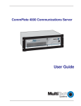
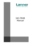
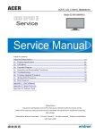
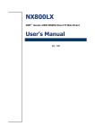
FW-7650 Series 19” 1U Intel Pentium4 / Celeron Rackmount Network Security Platform User’s Manual Copyright and Disclaimers © Copyright 2004 - Lanner Electronics Inc. All Rights Reserved The contents in this publication have been thoroughly checked and considered accurate. The publisher and manufacturer of this product, Lanner Electronics, is not responsible for any violation of patents or other rights of third parties resulting from its use. Neither does Lanner Electronics assume any responsibility for any inaccuracies contained in this manual, nor make any commitment to keep the information in this document up-to-date. Lanner reserves the right to make improvements to this document and/or this product at any given time without notice. No part of this document may be reproduced, stored in a retrieval system, or transmitted in any form or by any means (electronic, mechanical, photocopying, recording, or otherwise, without the formal consent from Lanner. Trademark Acknowledgments All products and/or brand names stated in this publication are the trademarks of their rightful and associated companies. Radio Frequency Emissions Notice This equipment has been tested and found to comply with the digital device limits pursuant to Part 15 of the FCC Rules. These limits are designed to provide reasonable protection against harmful interference when operate in a commercial environment. This equipment generates, uses, and can radiate radio frequency energy and, if not installed and used in accordance with the instruction manual, may cause harmful interference to radio communications. Operation of this equipment in a residential area may cause harmful interference, in which case the user will be required to correct the interference at his expense. ii Safety Instructions The following information relates to the safety of installation and maintenance personnel. Read all instructions before attempting to unpack, install or operate this equipment, especially before connecting the power adapter. Please keep the following in mind as you unpack and install this equipment: Always follow basic safety precautions to reduce the risk of fire, electrical shock and injury to persons. Do not apply power into FW-7650 before installation or when disconnecting this product from its original system setup. To prevent fire or shock hazard, do not expose the unit to rain, moisture or install this product near water. Locate a safe and dry location to place this product. Keep it away from wet surfaces/surroundings. Never push an object of any kind into this product through openings or empty slots, as you may damage parts. Do not attach the power supply cabling to building surfaces. Do not allow anything to rest on the power cabling or allow it to be abused by persons walking on it. Distance your working area from moist floors, ungrounded power extension cables, and unavailable safety grounds. Avoid installation of this product during a lighting storm. Damages caused by electrostatic discharge may result in total or intermittent system failures. To minimize the possibility of ESD damage, an anti-static strap is highly recommended. When cleaning or servicing this unit, avoid using highly toxic or aerosol cleaners. Use a clean damp cloth when wiping its surfaces. Do not place this device in a tight and sealed location. Place the unit where it can access sufficient airflow to its vent holes (openings along its sides). Never block or cover these openings. Do not disassemble this product on your own. iii Getting Technical Assistance Should you encounter questions or problems with your FW-7650, Lanner Electronics is ready to assist you within the guidelines of our product support programs. First, check the electronic product documentation for assistance. If you still cannot find the solution to your problem, contact Lanner sales team with the following information handy: FW-7650 model name Part number Local network configuration details The abnormal behavior and/or error messages reported by your network system Your questions, or a description of the problem you are experiencing Call, fax, or e-mail Lanner Electronics for technical support. Phone: 886-2-8692-6060 Fax: 886-2-8692-6101 E-mail: [email protected] About this Manual This target audience of this manual includes users, administrators and technicians. This publication is a useful reference when installing, configuring, operating and managing the FW-7650. This breakdown and short descriptions of this manual’s contents are as follows: Chapter 1 – Introduction provides an overview of the FW-7650 19” 1U Rackmount network security appliance, including its related features, application usage and technical specifications list. The chapter also guides users through the pre and post installation process by listing safety tips plus an overall detailed description of the control board and system and their vital components. Chapter 2 – Introduce Hardware Installation Chapter 3 – Award BIOS Setup Appendix A –summarizes the specification of the power supply Appendix B –Watchdog Timer Introduction Appendix C –Console Redirection Appendix D– LCD Module and Key Pad iv Table of Contents Copyright and Disclaimers....................................................................................................ii Trademark Acknowledgments...............................................................................................ii Radio Frequency Emissions Notice..................................................................... ii Safety Instructions ............................................................................................... iii Getting Technical Assistance .............................................................................. iv About this Manual................................................................................................ iv Table of Contents ................................................................................................ v C h a p t e r 1.........................................................................................................................1 Getting Started 1 1.1 Introduction.................................................................................................. 1 1.1.1 Features ............................................................................................................................... 1 1.2 Technical Specifications.............................................................................. 2 1.3 Packing Contents ........................................................................................ 3 1.4 MB-X71 System Board................................................................................ 4 1.4.1 1.4.2 1.4.3 Board Layout ........................................................................................................................ 4 Jumper Settings and I/O Connector ..................................................................................... 5 Connector Pin Assignments ................................................................................................. 6 SFC1:Master/Slave Select ................................................................................. 6 CMOS1:Clear CMOS Data ............................................................................... 6 FAN1~3 : 3 Pin FAN Connector.................................................................... 6 LANA1~2 :Type 1 ( RJ-45)............................................................................... 6 LANA3~6 :Type 1 ( RJ-45).............................................................................. 7 COMA1: RS-232 Serial Port #1 Connector ( D-Sub) ................................ 7 PKMB1:PS/2 Keyboard & Mouse Connector (2x4 Header 2.54mm)..... 7 PSA1:20 Pin ATX Power Connector ........................................................... 7 PSA1:20 Pin ATX Power Connector ........................................................... 8 PS4P1:4-Pin Power Connector (P4-4P Male ).......................................... 8 KPA1:LCM Keypad ...................................................................................... 8 LCMA1:LCM CONNECTOR....................................................................... 8 VGAB1 : External VGA Connector ( 12 Pin Header )...................................... 9 IDEA1 : IDE Interface Connector ( 44Pin 2.0mm Pitch Header ) .................... 9 PLRS1:Power LED,HD LED,Reset,Speaker Connector(11 Pin 2.54mm ) ..... 10 FDCA1 : Floppy Interface Connector ( 34 Pin Header ) ................................. 10 CF1:Compact Flash Connector ...................................................................11 LEDE1:2x22 Pin......................................................................................... 12 IDEB1 : IDE Interface Connector ( 40Pin 2.54mm Pitch Header).................. 13 PCIB1:124 Pin Mini PCI Socket ..................................................................... 14 PCIB1:124 Pin Mini PCI Socket(Continued last page) ............................... 15 1.5 FW-7650 19” 1U Rackmount Firewall Mechanisms .................................... 16 1.5.1 1.5.3 Face Panel ........................................................................................................................... 16 Rear View............................................................................................................................. 17 C h a p t e r 2.......................................................................................................................18 FW-7650 Hardware Installation Guide..............................................................................18 2.1 Hardware Installation Guide ........................................................................ 18 Chapter 3..............................................................................................................................22 Award BIOS Setup..............................................................................................................22 3.1 BIOS Setup ................................................................................................. 22 3.2 CMOS Setup Utility ...................................................................................... 23 3.3 Standard CMOS Features ........................................................................... 25 v 3.4 BIOS Features Setup .................................................................................. 27 3.5 Chipset Features Setup............................................................................... 30 3.6 Integrated Peripherals ................................................................................. 32 3.7 Power Management Setup .......................................................................... 34 3.8 PnP/PCI Configuration ................................................................................ 36 3.9 PC Health Status ......................................................................................... 40 3.10 Load Optimized Defaults ............................................................................. 41 3.11 Supervisor/User Password Setting ........................................................... 41 3.12 Save and Exit Setup ................................................................................... 41 3.13 Exit Without Saving ..................................................................................... 42 Appendix A...........................................................................................................................43 Power Supply 43 Appendix B ..........................................................................................................................44 Watchdog Timer 44 A p p e n d i x C...................................................................................................................46 Console Redirection ............................................................................................................46 A p p e n d i x D ..................................................................................................................47 LCD Module and Key Pad For FW-7650...........................................................................47 Terms and Conditions........................................................................................................................ 49 Warranty Policy 49 RMA Service 49 vi Chapter 1 Getting Started 1.1 Introduction Figure 1 – FW-7650 Outlook The FW-7650 is a 1U rackmount network security solution targeting the Enterprise market. The FW-7650 supports Petium4 /Celeron processor with 400/533MHz FSB. It is designed with an Intel 845GV as its northbridge and ICH4(82801DB) as its southbridge.; To enhance network security appliance, FW-7650 comes with Intel 82540EM & 82551QM Ethernet chips and six Ethernet LAN ports from 10/100Mbit up to Gigabit to provide an ideal price/performance solution for building a wide range of desktop and set top boxes to thin clients and web terminals powerful computing and multimedia performance for all the most popular productivity and Internet applications. Designed with the Plug-and-Serve concept in mind, the FW-7650 Series offers two DDR 200/266/333 DIMM Socket support up to 2GB RAM which provide full functionality and performance to be used "exactly" where you need it as well. In addition, one ATA mode CompactFlash type II socket used in installing OS avoiding service disruption caused by hard disk's mechanical/magnetic failures. The FW-7650 has a Mini PCI slot, users can expand their specifications and performance by simply adding add-on cards to the slot. The FW-7650 is a powerful and flexible unit that can meet the vast and various hardware requirement and performance needs of System Integrators, OEM customers and software developers. 1.1.1 Features Listed below are the key features of FW-7650. Supports 2.5” HDD Socket 478 for Intel® Pentium™ 4/Celeron Processor, up to 2.4GHz, 400/ 533MHZ FSB Two DDR200/266/333 DIMM Socket, up to 2GB RAM Supports Two Gigabit Ethernet ports, with two Intel 82540EM chipset. And Four 10/100 Ethernet ports, with four intel 82551QM chipset Supports Compact Flash, Serial(RS-232), and Mini PCI. 19”1U Rackmount network security appliance Suitable Network applications; Virtual Private Network(VPN), Firewall, IDS, … 1 1.2 Technical Specifications Model Name FW-7650 SBC SBC MB-X71 CPU Socket 478 for Intel® Pentium™ 4/Celeron Processor, up to 2.4GHz,533MHZ FSB Chipset Intel® 845GV chipset (pin-to-pin compatible with 845G series); 82801DB I/O Controller Hub 4 (ICH4) BIOS Award BIOS Memory Two DDR200/266/333 DIMM Socket, up to 2GB RAM A. Two Intel 82540EM 32bit Gb Ethernet Controller (Colay Network interface with 82551QM) B. Four Intel 82551QM 10/100 Mb Ethernet Controller SSD Two CompactFlash TypeII Socket I/O Interface One DB-9 RS-232 connector Expansion Slot One Mini-PCI slot RTC Internal RTC with LI battery Power 200W ATX Power Supply Mechanical/ Environmental Form Factor 19” 1U Rackmount Operating Temperature 0 oC – 40 oC Storage Temperature -20 oC – 70 oC Humidity 5% - 95% RH, non-condersing Chassis Material Steel Dimension 428x303x44 mm 5.4 KGS Net Weight Certification CE, FCC CLASS A Software support Linux 6.5 and above, Windows 2000/2003/ XP 2 1.3 Packing Contents Carefully unpack your package and make sure that you have the following items. FW-7650 Network security Platform Console cable 1.8 meters long cross-over Ethernet cable 1.8 meters long straight-through Ethernet cable Face panel name plate label Power cable Drivers and User’s Manual CD Screw Set Slid & Bracket Set If you find anything missing or damaged, promptly contact your dealer for assistance. 3 1.4 MB-X71 System Board MB-X71 is the system board bundled with the FW-7650 Network security platform. The succeeding sections list all MB-X71 related jumper settings and connector pin assignments. 1.4.1 Board Layout Figure 3 – MB-X71 Jumpers and Connectors 4 1.4.2 Jumper Settings and I/O Connector The onboard jumper settings and I/O connector of MB-X71 are custom-tailored to fit the FW-7650 functionality. Changing the jumper settings may result in system malfunction or unforeseen damages. Jumper Settings and I/O Connector Summary for MB-X71 JUMPER CMOS1 FUNCTION Clear CMOS Data SCF1 Master/Slave Select FAN1-3 3 Pin Fan Connector LANA1~2 Type 1 ( RJ-45 ) LANA3~6 Type 1 ( RJ-45) COM1 RS232 Serial Port #1 Connector (D-Sub) PKMB1 PS/2 Keyboard & Mouse Connector (2x4 Header 2.54mm ) PSA1 20 Pin ATX Power Connector PS4P1 4-Pin Power Connector (P4-4P Male ) KPA1 LCM Keypad LCMA1 LCM CONNECTOR VGAB1 External VGA Connector ( 12 Pin Header ) IDEA1 IDE Interface Connector ( 44 Pin 2.0mm Pitch Header ) IDEB1 IDE Interface Connector ( 40 Pin 2.54mm Pitch Header ) PLRS1 Power LED, Reset, Speaker Connector FDCA1 Floppy Interface Connector (34 Pin Header) CF1 Compact Flash Connector LEDE1 2x22 Pin PCIB1 124 Pin Mini PCI Socket 5 1.4.3 Connector Pin Assignments SFC1:Master/Slave Select Compact Flash Card ATA Disk Chip SCF1 Master Slave Slave Master 1-2 2-3(Default CMOS1:Clear CMOS Data CMOS1 Description Normal (Default) Clear CMOS 1-2 2-3 FAN1~3 : 3 Pin FAN Connector Pin No. Description 1 2 3 Ground +12V FAN Status LANA1~2 :Type 1 ( RJ-45) Description Pin No. 1 2 3 4 5 6 7 8 Fast Ethernet Giga Ethernet TX+ TXRX+ T45 T45 RXT78 T78 MD0+ MD0MD1+ MD2+ MD2MD1MD3+ MD3- 6 LANA1~2 LANA3~6 :Type 1 ( RJ-45) Pin No. Description 1 2 3 4 5 6 7 8 TX+ TXRX+ T45 T45 RXT78 T78 COMA1: RS-232 Serial Port #1 Connector ( D-Sub) Pin No. Description 1 2 3 4 5 6 7 8 9 Data Carrier Detect ( DCDA # ) Receive Data ( RXDA ) Transmit Data ( TXDA ) Data Terminal Ready ( DTRA # ) Ground ( GND ) Data Set Ready ( DSRA # ) Request To Send ( RTSA # ) Clear To Send ( CTSA # ) Ring Indicator ( RIA # ) PKMB1:PS/2 Keyboard & Mouse Connector (2x4 Header 2.54mm) Pin No. Description Pin No. Description 1 3 5 7 KBCLK NC NC MSCLK 2 4 6 8 GND KBDATA MSDATA VCC 7 COMA1 PSA1:20 Pin ATX Power Connector Pin No. Description Pin No. Description 1 2 3 4 5 6 7 8 9 10 +3.3V +3.3V GND +5V GND +5V GND Power Good Stand-By 5V +12V 11 12 13 14 15 16 17 18 19 20 +3.3V -12V GND SWITCH GND GND GND -5V +5V +5V PS4P1:4-Pin Power Connector (P4-4P Male ) Pin No. Description 1 2 3 4 GND GND +12V +12V KPA1:LCM Keypad Pin No. Description 1 2 3 4 KPA1 KPA2 KPA3 KPA4 LCMA1:LCM CONNECTOR Pin No. Description Pin No. Description 1 3 5 7 9 11 13 15 VCC LSTINLAFDLPD1 LPD3 LPD5 LPD7 LCD 2 4 6 8 10 12 14 16 PGND VEE LINITLPD0 LPD2 LPD4 LPD6 VCC 8 VGAB1 : External VGA Connector ( 12 Pin Header ) Pin No. Description Pin No. Description 1 3 5 7 9 R G B H-SYNC V-SYNC Detect-display Data 2 4 6 8 10 Ground Ground Ground Ground Ground Deteck-display CLOCK 11 12 IDEA1 : IDE Interface Connector ( 44Pin 2.0mm Pitch Header ) Pin No. Description Pin No. Description 1 3 5 7 9 11 13 15 17 19 21 23 25 27 29 31 33 35 37 39 41 43 Reset # Data 7 Data 6 Data 5 Data 4 Data 3 Data 2 Data 1 Data 0 Ground DMA REQ # IOW # IOR # IOCHRDY DMA ACK # Interrupt SA 1 SA 0 HDC CS 0# HDD Active VCC Ground 2 4 6 8 10 12 14 16 18 20 22 24 26 28 30 32 34 36 38 40 42 44 Ground Data 8 Data 9 Data 10 Data 11 Data 12 Data 13 Data 14 Data 15 NC Ground Ground Ground Ground Ground NC NC SA 2 HDC CS 1# Ground VCC NC 9 PLRS1:Power LED,HD LED,Reset,Speaker Connector(11 Pin 2.54mm ) Pin No. Description 1 2 3 4 5 6 7 8 9 10 11 Power LED + Power LED + GND HDD LED + HDD LED RESET SW + RESET SW – (GND) External Speaker Internal Buzzer NC External Speaker + FDCA1 : Floppy Interface Connector ( 34 Pin Header ) Pin No. Description Pin No. Description 1 3 5 7 9 11 13 15 17 19 21 23 25 27 29 31 33 Ground Ground Ground Ground Ground Ground Ground Ground Ground Ground Ground Ground Ground Ground NC Ground NC 2 4 6 8 10 12 14 16 18 20 22 24 26 28 30 32 34 Density Select NC DS1 Index # Motor Enable A # Drive Select B # Drive Select A # Motor Enable B # Direction # Step # Write Data # Write Gate # Track 0 # Write Protect # Read Data # Head Side Select # Disk Change # 10 CF1:Compact Flash Connector Pin No. Description Pin No. Description 1 2 3 4 5 6 7 8 9 10 11 12 13 14 15 16 17 18 19 20 21 22 23 24 25 GND DATA3 DATA4 DATA5 DATA6 DATA7 CE1# A10 OE# A9 A8 A7 CFVCC3 A6 A5 A4 A3 A2 A1 A0 DATA0 DATA1 DATA2 WP CD2- 26 27 28 29 30 31 32 33 34 35 36 37 38 39 40 41 42 43 44 45 46 47 48 49 50 CD1DATA11 DATA12 DATA13 DATA14 DATA15 CE2# VS1# IOR# IOW# WE# READY# CFVCC3 CSEL VS2# RESET WAIT# INPACK# REG# DASP# DIAG# DATA8 DATA9 DATA10 GND 11 LEDE1:2x22 Pin Pin No. Description Pin No. Description 1 3 5 7 9 11 13 15 17 19 21 23 25 27 29 31 33 35 37 39 41 43 POWER LED POWER LED STATUS Lan1 Link/Active LEDLan1 100 LEDLan1 1G LEDLan2 Link/Active LEDLan2 100 LEDLan2 1G LEDLan3 Link/Active LEDLan3 100 LEDLan3 1G LEDLan4 Link/Active LED Lan4 100 LED Lan4 1G LED Lan5 Link/Active LED Lan5 100 LED Lan5 1G LED Lan6 Link/Active LED Lan6 100 LED Lan6 1G LED NC NC 2 4 6 8 10 12 14 16 18 20 22 24 26 28 30 32 34 36 38 40 42 44 POWER LED POWER LED STATUS Lan1 Link/Active LED+ Lan1 100 LED+ Lan1 1G LED+ Lan2 Link/Active LED+ Lan2 100 LED+ Lan2 1G LED+ Lan3 Link/Active LED+ Lan3 100 LED+ Lan3 1G LED+ Lan4 Link/Active LED Lan4 100 LED Lan4 1G LED Lan5 Link/Active LED Lan5 100 LED Lan5 1G LED Lan6 Link/Active LED Lan6 100 LED Lan6 1G LED NC NC 12 IDEB1 : IDE Interface Connector ( 40Pin 2.54mm Pitch Header) Pin No. Description Pin No. Description 1 3 5 7 9 11 13 15 17 19 21 23 25 27 29 31 33 35 37 Reset # Data 7 Data 6 Data 5 Data 4 Data 3 Data 2 Data 1 Data 0 Ground DMA REQ# IOW # IOR # IOCHRDY DMA ACK # Interrupt SA1 SA0 HDC CS0 # HDD Active LED # 2 4 6 8 10 12 14 16 18 20 22 24 26 28 30 32 34 36 38 Ground Data 8 Data 9 Data 10 Data 11 Data 12 Data 13 Data 14 Data 15 NC Ground Ground Ground Ground Ground NC PD80P / SD80P SA2 HDC CS1 # 40 Ground 39 13 PCIB1:124 Pin Mini PCI Socket Pin No. Description Pin No. Description 1 3 5 7 9 11 13 15 17 19 21 23 25 27 29 31 33 35 37 39 41 43 45 47 49 51 53 55 57 59 TIP 8PMJ-3 8PMJ-6 8PMJ-7 8PMJ-8 LED1_GRNP LED1_GRNN CHSGND INT-B +3.3V RESERVED GROUND CLK GROUND REO +3.3V AD31 AD29 GROUND AD27 AD25 RESERVED C_BE-3 AD23 GROUND AD21 AD19 GROUND AD17 C_BE-2 2 4 6 8 10 12 14 16 18 20 22 24 26 28 30 32 34 36 38 40 42 44 46 48 50 52 54 56 58 60 RING 8PMJ-1 8PMJ-2 8PMJ-4 8PMJ-5 LED2_YELP LED2_YELP RESERVED +5V INT-A RESERVED 3.3VAUX RST +3.3V GNT GROUND PME RESERVED AD30 +3.3V AD28 AD26 AD24 IDSEL GROUND AD22 AD20 PAR AD18 AD16 14 PCIB1:124 Pin Mini PCI Socket(Continued last page) Pin No. Description Pin No. Description 61 63 65 67 69 71 73 75 77 79 81 83 85 87 89 91 93 95 97 99 101 103 105 107 109 111 113 115 IRDY +3.3V CLKRUN SERR GROUND PERR C_BE-1 AD14 GROUND AD12 AD10 GROUND AD8 AD7 +3.3V AD5 RESERVED AD3 +5V AD1 GROUND AC_SYNC AC_SDATA_IN AC_BIT_CLK AC_CODEC_ID1 MOD_AUDIO_MON AUDIO_GND SYS_AUDIO_OUT SYS_AUDIO_OUT GND AUDIO_GND RESERVED VCC5VA 62 64 66 68 70 72 74 76 78 80 82 84 86 88 90 92 94 96 98 100 102 104 106 108 110 112 114 116 GROUND FRAME TRDY STOP +3.3V DEVSEL GROUND AD15 AD13 AD11 GROUND AD9 C_BE-0 +3.3V AD6 AD4 AD2 AD0 RESERVED-WIP RESERVED-WIP GROUND M66EN AC_SDATA_OUT AC_CODEC_ID0 AC_RESET RESERVED GROUND SYS_AUDIO_IN 118 SYS_AUDIO_IN GND 120 122 124 AUDIO_GND MPCIACT 3.3AUX 117 119 121 123 15 1.5 FW-7650 19” 1U Rackmount Firewall Mechanisms This section of the manual describes the mechanical and device nomenclature of FW-7650. 1.5.1 Face Panel LED Indicator Key PAD Console LCM 10/100 LAN Connector 2.5” Hdd Bay Gigabit LAN Connector Figure 5 – FW-7650 Face Panel Face Panel LED Status and Behavior The following table lists and explains the behavior of each LED on the FW-7650 front panel. LED Color Status PWR Green N/A On Off Status Green/Red Ethernet Ports Ethernet Ports Link/ACT Description When FW-7650 power is switched ON No power connected Programmable via GPIO N/A The speed of LAN is 10Mbit/s Green The speed of LAN is 100Mbit/s Orange The speed of LAN is 1000Mbit/s Green Orange On When LAN is connected Flash When Data is accessing Lanner provide the LED status sample in the path //FW-7650_MB-X71/ LED_Sample_Code Console Port: via the console port cable, this connector attaches FW-7650 to the host PC. The Default baud rate is 115200. LAN Connector: Ethernet RJ-45 connector, connected to networking environment using a RJ-45 Ethernet cable LCM & Keypad Please reference the Appendix B 16 1.5.3 Rear View Blowhole Power Socket Power Switch Figure 6 – FW-7650 Rear View Power Switch: Click the Power Switch , and the system will be power on. Faulty or improper use of the power adaptor may cause permanent damage to the power supply and the FW-7650. Plug the adaptor to an electrical wall outlet that matches its specifications. 17 Chapter 2 FW-7650 Hardware Installation Guide 2.1 Hardware Installation Guide Inside of FW-7650 - CPU Installation Step 1: Locate the ZIF socket and open it by first pulling the lever of socket upward. Step 2: Insert the CPU into the socket. Please keep the lever right angle when inserting CPU. Step 1 Step 2 Step 3: When inserting the CPU please note the correct orientation as shown. The notched corner should point toward the end of the lever Step 4: Push the lever down to close the socket. Step 3 Step 4 Step 5: Please take the screw off. Step 6: Please find a cooler (Fan+Heat Sink) within the packing, attach it into the CPU. Step 5 Step 7: Finally, connect the fan cable to the CPU fan header. - System Memory Step 1: Open latches of DIMM socket Step 2: Insert the RAM module into the DIMM socket. Step 6 Step 3: Press the latches into the notches of the RAM module. How to Remove the Hard Disk Bay Step 1: Open both latches of mobile rack by press it. Step 2: Use two hands to pull out the mobile rack. Step 3: Remove the mobile rack straight and smooth. How to Remove the Hard Disk Bay Step 1: Use screwdriver to remove four screws on the cover Step 2: Pick up the cover Step 1 Step 2 Step 3: Connect the 44pin cable, and insert a 2.5” hard disk. Step 4: Screw the 2.5” hard disk from the bottom of the mobile rack, you may find the four screws within the packing. Step 3 Step 4 Step 5: Put the cover back. Step 6: Screw the cover. Step 6 Step 5 - Installing Compact Flash Card Step 1: Insert the compact flash card into the slot carefully as shown in the picture. Step 1 - Installing the Mini-PCI Card Step 1: Insert the PCI expansion card into the mini-PCI slot at 45 degree. Step 2: Push down the PCI expansion card and the PCI expansion card is clicked together completely with the PCI expansion slot. Step 1 Step 2 Chapter 3 Award BIOS Setup 3.1 BIOS Setup Award‘s ROM BIOS provides a built-in Setup program that allows users to modify the basic system configuration and settings. The modified data will be stored in a battery-backed CMOS RAM so that this data will be retained even when the power is turned off. In general, the information saved in the CMOS RAM remains unchanged unless there is a configuration change in the system, such as hard drive replacement or new equipment installment. Starting Setup The AwardBIOS™ is immediately activated when you first power on the computer. The BIOS reads the system information contained in the CMOS and begins the process of checking out the system and configuring it. When it finishes, the BIOS will seek an operating system on one of the disks and then launch and turn control over to the operating system. While the BIOS is in control, the Setup program can be activated in one of two ways: 1. By pressing <Del> immediately after switching the system on, or 2. By pressing the <Del> key when the following message appears briefly at the bottom of the screen during the POST (Power On Self-Test). Press DEL to enter SETUP. If the message disappears before you respond and you still wish to enter Setup, restart the system to try again by turning it OFF then ON or pressing the "RESET" button on the system case. You may also restart by simultaneously pressing <Ctrl>, <Alt>, and <Delete> keys. If you do not press the keys at the correct time and the system does not boot, an error message will be displayed and you will again be asked to... PRESS F1 TO CONTINUE, DEL TO ENTER SETUP Using Setup In general, you use the arrow keys to highlight items, press <Enter> to select, use the PageUp and PageDown keys to change entries, press <F1> for help and press <Esc> to quit. The following table provides more detail about how to navigate in the Setup program using the keyboard. < > Move to previous item < > Move to next item < > Move to the item in the left hand < > Move to the item in the right hand Enter Select item <Esc> Main Menu - Quit and not save changes into CMOS Status Page Setup Menu and Option Page Setup Menu - Exit current page and return to Main Menu <+/PgUp> Increase the numeric value or make changes <-/PgDn> Decrease the numeric value or make changes <F1> General help, only for Status Page Setup Menu and Option Page Setup Menu <F2> Item Help <F5> Restore the previous CMOS value from CMOS, only for Option Page Setup Menu <F7> Load the Optimized Defaults <F9> System Information <F10> Save all the CMOS changes, only for Main Menu Navigating through the menu bar Use the left and right arrow keys to choose the menu you want to be in. To display a sub menu, use the arrow keys to move the cursor to the sub menu you want. Then press <Enter>. A “!” pointer marks all sub menus. Getting Help Press F1 to pop up a small help window that describes the appropriate keys to use and the possible selections for the highlighted item. To exit the Help Window press <Esc> or the F1 key again. 3.2 CMOS Setup Utility Once you enter the AwardBIOS™ CMOS Setup Utility, the Main Menu will appear on the screen. The Main Menu allows you to select from several setup functions and two exit choices. Use the arrow keys to select among the items and press <Enter> to accept and enter the sub-menu. Listed below are explanation of the keys displayed at the bottom of the screen: <ESC> : Exit the utility. <Ç È Æ Å> : Use arrow keys Ç È Æ Å to move cursor to your desired selection. <F1> : General Help <F5> : Previous Values <F6> : Fail-Safe Defaults <F7> : Optimized Defaults <F10> : Saves all changes made to Setup and exits program. +/-/PU/PD : Change Value Note that a brief description of each highlighted selection appears at the bottom of the screen. Standard CMOS Setup: Use this menu for basic system configurations. Advanced BIOS Features: Use this menu to set the Advanced Features available on your system Advanced Chipset Features: Use this menu to change the values in the chipset registers and optimize your system’s performance Integrated Peripherals: Use this menu to specify your settings for integrated peripherals. PnP/PCI Configuration: This entry appears if your system supports PnP/PCI. PC Health Status: This entry shows your PC health status. If Hardware Monitor Chipset is installed. Load Optimized Defaults: Use this menu to load the BIOS default values that are factory settings for optimal performance system operations. Set Supervisor Password: Use this menu to set Supervisor Passwords Set User Password: Use this menu to set User Passwords. Save & Exit Setup: Save CMOS value changes to CMOS and exit setup Exit Without Saving: Abandon all CMOS value changes and exit setup 3.3 Standard CMOS Features The items in Standard CMOS Setup Menu are divided into 9 categories. Each category includes no, one or more than one setup items. Use the arrow keys to highlight the item and then use the <PgUp> or <PgDn> keys to select the value you want in each item. Item Options Date Month DD YYYY Time IDE Channel 0 Master HH : MM : SS Options are in its sub menu IDE Channel 0 Slave Options are in its sub menu IDE Channel 1 Master IDE Channel 2 Master Options are in its sub menu Options are in its sub menu Halt On All Errors No Errors All, but Keyboard All, but Diskette All, but Disk/Key Base Memory N/A Extended Memory N/A Total Memory N/A Description Set the system date. Note that the ‘Day’ automatically changes when you set the date Set the system time Press <Enter> to enter the sub menu of detailed options Press <Enter> to enter the sub menu of detailed options Press <Enter> to enter the sub menu of detailed options Press <Enter> to enter the sub menu of detailed options Select the situation in which you want the BIOS to stop the POST process and notify you Displays the amount of conventional memory detected during boot up Displays the amount of extended memory detected during boot up Displays the total memory available in the system IDE Adapters The IDE adapters control the hard disk drive. Use a separate sub menu to configure each hard disk drive. IDE Primary Master sub menu Use the legend keys to navigate through this menu and exit to the main menu. Use Table 1 to configure the hard disk. Item IDE HDD Auto-detection Options Press Enter Description Press Enter to auto-detect the HDD on this channel. If detection is successful, it fills the remaining fields on this menu. IDE Channel 0 Master Capacity Access Mode Cylinder Head Precomp Landing zone Sector Selecting ‘manual’ lets you set the remaining fields on this screen. Selects the type of fixed disk. "User Type" will let you select the number of cylinders, heads, etc. Note: PRECOMP=65535 means NONE ! Auto Display Disk drive capacity (Approximated). Note that this size is your disk drive usually slightly greater than the size of a formatted disk size given by a disk checking program. CHS LBA Choose the access mode for this hard disk Large Auto Min = 0 Set the number of cylinders for this hard disk. Max = 65535 Min = 0 Set the number of read/write heads Max = 255 Min = 0 **** Warning: Setting a value of 65535 means no hard disk Max = 65535 Min = 0 **** Max = 65535 Min = 0 Number of sectors per track Max = 255 None Auto Manual 3.4 BIOS Features Setup This section allows you to configure your system for basic operation. You have the opportunity to select the system’s default speed, boot-up sequence, keyboard operation, shadowing and security. Virus Warning: The default setting of Virus Warning is “Disabled”. When it is enabled, any attempt to write the boot sector and partition table will halt the system and cause a warning message to appear. If this happens, you can use an anti-virus utility on a virus free, bootable floppy diskette to reboot, to clean and to investigate your system. Quick Power On Self Test : The default setting is “Enabled”. This speeds up the Power On Self Test (POST) by skipping some items that are normally checked during the full POST. If your system is functioning normally, you can choose this feature to speed up the booting process. First / Second / Third / Other Boot Device : The BIOS attempts to load the operating system from the devices in the sequence selected in these items. The settings are Floppy, LS/ZIP, HDD-0/HDD-1/HDD-2/HDD-3, SCSI, CDROM, LAN, and Disabled Swap Floppy Drive : The default setting is “Disabled”. This setting gives you an option to swap A and B floppy disks. Normally, the floppy drive A is the one at the end of the cable and drive B is at the other end. If you set this option to “Enabled”, the Drive A will function as Drive B, and vice-versa under the DOS. Floppy Disk Access Control: This option specifies the read/write access that is set when booting from a Floppy disk drive. The settings are Read/Write or Read-Only. The Optimal and Fail-Safe default settings are Read/Write. Boot Up Numlock Status : The default setting is “On”. If set “Off”, the cursor controls will function on the numeric keypad. Security Option : This setting controls the password in the main screen. The options are “Setup” and “System”. Select “Setup” and it will protect the Setup Utility settings from being tampered with. Select “System” if you want to use password feature every time the system boots up. The default setting is “Setup”. You can create your password by using the “SUPERVISOR/USER PASSWORD” utility on the main program screen. PS/2 Mouse Function Control : When this option is set Enabled, AMIBIOS supports a PS/2 type mouse. The settings are Enabled or Disabled. The default setting is Disabled. System Boot Up Sequence. HDD S.M.A.R.T. for Capability : This allows you to activate the S.M.A.R.T. (Self-Monitoring Analysis & Reporting Technology) capability for the hard disks. S.M.A.R.T is a utility that monitors your disk status to predict hard disk failure. This gives you an opportunity to move data to a safe place before the hard disk becomes offline. Settings: Enabled and Disabled. Video BIOS Shadow : The default setting is “Enabled” which will copy the VGA display card BIOS into system DRAM to improve performance. C8000-CBFFF Shadow to DC000-DFFFF Shadow : The default setting for the shadow feature is “Disabled”. When enabled, the ROM with the specific address is copied into system DRAM. It will also reduce the size of memory available to the system. After you have made your selection in the BIOS FEATURES SETUP, press the <ESC> key to go back to the main program screen. 3.5 Chipset Features Setup DRAM Clock : The chipset support synchronous and asynchronous mode between the host clock and DIMM clock. Host CLK (default) DIMM clock equal to host clock 66MHz DIMM clock equal to 66MHz SDRAM Cycle Length : This item allows you to select the SDRAM cycle length. The settings are 2 or 3. CAS latency Time: When synchronous DRAM is installed, the number of clock cycles of CAS latency depends on the DRAM timing. Do not reset this field from the default value specified by the system designer. DRAM RAS# to CAS# Delay: This field lets you insert a timing delay between the CAS and RAS strobe signals, used when DRAM is written to, read from, or refreshed. Fast gives faster performance. This field applies only when synchronous DRAM is installed in the system. DRAM RAS# Precharge Time: If an insufficient number of cycles is allowed for the RAS to accumulate its charge before DRAM refresh, the refresh may be incomplete and the DRAM may fail to retain data. Fast gives faster performance; and Slow gives more stable performance. This field applies only when synchronous DRAM is installed in the system. System BIOS Cacheable : Selecting “Enabled” allows caching of the system BIOS ROM at F0000h – FFFFFh, resulting in better system performance. However, if any program writes to this memory area, a system error may result. The settings are “Enabled” and “Disabled”. Video BIOS Cacheable: Selecting Enabled allows caching of the video BIOS ROM at C0000h to C7FFFh, resulting in better video performance. However, if any program writes to this memory area, a system error may result. Memory Hole At 15M-16M: You can reserve this area of system memory for ISA adapter ROM. When this area is reserved, it cannot be cached. The user information of peripherals that need to use this area of system memory usually discusses their memory requirements. AGP Aperture Size : Select the size of the Accelerated Graphics Port (AGP) aperture. The aperture is a portion of the PCI memory address range dedicated for graphics memory address space. Host cycles that hit the aperture range are forwarded to the AGP without any translation 3.6 Integrated Peripherals On-Chip (Primary/Secondary) PCI IDE : The Intel 82C440BX chipset contains a PCI IDE interface with support for two IDE channels. Select Enabled to activate the primary and/or secondary IDE interface. Select Disabled to deactivate this interface, if you install a primary and/or secondary add-in IDE interface. IDE Prefetch Mode : The onboard IDE drive interfaces supports IDE prefetching for faster drive accesses. If you install a primary and/or secondary add-in IDE interface, set this field to Disabled if the interface does not support prefetching. The settings are “Enabled” and “Disabled”. Select Enabled if your system contains a Universal Serial Bus (USB) controller and you have USB peripherals USB Controller: USB Keyboard Support : Select Enabled if your system contains a Universal Serial Bus (USB) controller and you have a USB keyboard. Init Display First : This item allows you to decide to active whether PCI Slot of VGA card or AGP first. The settings are “PCI Slot” and “AGP Slot”. Onboard FDD Controller : Select Enabled if your system has a floppy disk controller (FDC) installed on the system board and you want to use it. If you install add-in FDC or the system has no floppy drive, select Disabled in this field. The settings are “Enabled” and “Disabled”. Onboard Serial Port 1 : Select an address and corresponding interrupt for the first and second serial ports. The settings are “3F8/IRQ4”, “2E8/IRQ3”, “3E8/IRQ4”, “2F8/IRQ3”, “Disabled”, “Auto” 3.7 Power Management Setup The Power Management Setup allows you to configure you system to most effectively save energy while operating in a manner consistent with your own style of computer use. This category allows you to select the type (or degree) of power saving and is directly related to the following modes: 1. HDD Power Down 2. Doze Mode 3. Suspend Mode There are four selections for Power Management, three of which have fixed mode setting Disable (Default) No power management. Disables all four modes. Minimum power management. Doze Mode=1hr. Standby Mode =1hr., Suspend Min. Power Saving Mode=1hr., and HDD Power Down=15min. Maximum power management. –Only available for SL CPU’s. Doze Max. Power Saving Mode=1min., Standby Mode=1min., Suspend Mode=1min., and HDD Power Down=1min. Allows you to set each mode individually. When not disabled, each of the ranges User Defined are from 1 min. to 1 hr. except for HDD Power Down which ranges from 1 min. to 15 min. and disabled. Video Off Option : This option is for choosing the setting in which the monitor will turn off. The default setting is “Suspend” N/A Always turn on. Doze During Doze mode, the monitor will be turned off. Standby During Standby mode, the monitor will be turned off. Suspend During Suspend mode, the monitor will be turned off. Video Off Method : This determines the manner in which the monitor is blanked. The default setting is “V/H SYNC+Blank”. V/H SYNC+Blank This selection will cause the system to turn off the vertical and horizontal synchronization ports and write blank to the video buffer. Blank Screen This option only writes blanks to the video buffer. DPMS Initial display power management signaling. Suspend Mode : Option are from “1 Min” to “1 Hour” and “Disable”. The CPU clock will be stopped and the video signal will be suspended, if no Power Management events occur for a specified length of time. Full power function will return when a Wake-Up event is detected. HDD Power Down: Options are from “1 Min”. to “15 Min”. and “Disable”. The IDE hard drive will spin down if it is not accessed within a specified length of time. 3.8 PnP/PCI Configuration This section describes configuring the PCI bus system. PCI, or Personal Computer Interconnect, is a system which allows I/O devices to operate at speeds nearing the speed the CPU itself uses when communicating with its own special components. This section covers some very technical items and it is strongly recommended that only experienced users should make any changes to the default settings. PnP OS Installed : When set to “Yes”, BIOS will only initialize the PnP cards used for booting (VGA, IDE, SCSI). The rest of the cards will be initialized by the PnP operating system like Windows® 95 or 98. When set to “No”, BIOS will initialize all the PnP cards. So, for non-PnP operating system (DOS, Netware®), this option must set to “Yes”. Reset Configuration Data : Normally, you leave this field “Disabled”, Select “Enabled” to reset Extended System Configuration Data (ESCD) when you exit Setup if you have installed a new add-on and the system reconfiguration has caused such a serious conflict that the operating system cannot boot. The settings are : “Enabled and Disabled”. Resource Controlled By : The Award Plug and Play BIOS has the capacity to automatically configure all of the boot and Plug and Play compatible devices. However, this capability means absolutely nothing unless you are using a Plug and Play operating system such as Windows®98. If you set this field to “Manual” choose specific resources by going into each of the sub menu that follows this field ( a sub menu is proceded by a “►”). The settings are “Auto(ESCD)”, “Manual”. IRQ Resources : When resources are controlled manually, assign each system interrupt as one of the following types, depending on the type of device using the interrupt. IRQ3/4/5/7/9/10/11/14/15: These items specify the bus where the specified IRQ line is used. The settings determine if AMIBIOS should remove an IRQ from the pool of available IRQs passed to devices that are configurable by the system BIOS. The available IRQ pool is determined by reading the ESCD NVRAM. If more IRQs must be removed from the IRQ pool, the end user can use these settings to reserve the IRQ by assigning an ISA/EISA setting to it. Onboard I/O is configures by AMIBIOS. All IRQs used by onboard I/O are configured as PCI/PnP. If all IRQs are set to ISA/EISA, and IRQ14/15 are allocated to the onboard PCI IDE, IRQ9 will still be available for PCI and PnP devices. Settings: ISA/EISA and PCI/PnP. DMA Resources : The sub menu can let you control the DMA resource. DMA Resources : The sub menu can let you control the DMA resource. DMA Channel 0/1/3/5/6/7: These items specify the bus that the system DMA(Direct Memory Access) channel is used. The settings determine if AMIBIOS should remove a DMA from the available DMAs passed to devices that are configurable by the system BIOS. The available DMA pool is determined by reading the ESCD NVRAM. If more DMAs must be removed from the pool, the end user can reserve the DMA by assigning an ISA/EISA setting to it. Reserved Memory Size : This option specifies the size of the memory area reserved for legacy ISA adapter cards. The settings are Disabled, 16K, 32K, or 64K. The optimal and Fail-Safe default settings are Disabled. Reserved Memory Address: This option specifies the beginning address (in hex) of the reserved memory area. The specified ROM memory area is reserved for use by legacy ISA adapter cards. This option does not appear if the Reserved Memory Size option is set to Disabled. The settings are C0000,C4000,C8000,CC000,D0000,D4000,D8000,or DC000. PCI/VGA Palette Snoop : Leave this field at “Disabled”. The settings are “Enabled”, “Disabled”. PCI Latency Timer (PCI Clocks): This option is used to control PCI latency timer period (follow PCI clocks). Based on PCI specification 2.1 or later and PCI bus frequency in system, user can select different timer to meet their PCI bus environment. 3.9 PC Health Status CPU Temperature, Fan1 Speed, Fan2 Speed , Fan2 Speed, VCORE, +2.5, +3.3V, +5V, +12V : These items display the current status of all monitored hardware devices/components such as system voltages, temperatures and fan speeds. 3.10 Load Optimized Defaults When you press “Enter” on this item, you get a confirmation dialog box with a message similar to: Load Optimized Defaults (Y/N) ? N Pessing “Y” loads the default values that are factory settings for optimal performance system operations 3.11 Supervisor/User Password Setting Te “SUPERVISOR/USER PASSWORD” utility sets the password. The SBC is shipped with the password disabled. If you want to change the password, you must first enter the current password, then at the prompt -- enter your new password. The password is case sensitive, and can be up to 8 alphanumeric characters. Press <Enter> after you have finished typing in the password. At the next prompt, confirm the new password by re-typing it and pressing <Enter> again. When you are done, the screen automatically reverts to the main screen. Remember that when you use this feature, the “Security Option” line in BIOS FEATURES SETUP will determine when entering the password will be required. To disable the password, press the <Enter> key instead of entering a new password when the “Enter Password” in the dialog box appears. A message will appear confirming that the password is disabled. If you have set both supervisor and user password, only the supervisor password allows you to enter the BIOS SETUP PROGRAM. Note : If you forget your password, the only way to solve this problem is to discharge the CMOS memory 3.12 Save and Exit Setup Pressing <Enter> on this item asks for confirmation: Save to CMOS and EXIT (Y/N)? Y Pressing “Y” stores the selections made in the menus in CMOS – a special section of memory that stays on after you turn your system off. The next time you boot your computer, the BIOS configures your system according to the Setup selections stored in CMOS. After saving the values the system is restarted again. 3.13 Exit Without Saving Pressing <Enter> on this item asks for confirmation: Quit without saving (Y/N)? Y This allows you to exit Setup without storing in CMOS any change. The previous selections remain in effect. This exits the Setup utility and restarts your computer. Appendix A Power Supply Power Supply Specification AC Input Spec : VOLTAGE 100 - 240 VAC FULL RANGE (±10% tolerance) Output Specifications Output Voltage Output Current Min. Output Current Max. Regulation Load Regulation Line Output Ripple & Noise Max 5V 3 25.00 ±5% ±1% 50mV 12V 2 8.00 ±7% ±1% 100mV -5V 0.05 0.50 ±10% ±1% 120mV -12V 0.05 0.50 ±10% ±1% 150mV 3.3V 1 1.4 ±5% ±1% 50mV +5VSB 0.1 1.5 ±5% ±1% 50mV Feature : *Active PFC (full range), MEET IEC-1000-3-2 CLASS D *TEMPERATURE RANGE: OPERATING 00C ---500C. *EMI NOISE FILTER: FCC CLASS B, CISPR22 CLASS B *SAFETY: UL 1950, CSA 22.2 NO/ 950, TUV IEC 950 *Remote on/off control *Cooling: ONE 40 mm DC Fan *3.3V /5V Remote sensing *Extend AC cable ( optional ) *Serial ATA optional Appendix B Watchdog Timer Introduction Most systems need to be self-reliant. It's not usually possible to wait for someone to reboot them if there are some component wrong. Some system designs, such as space probes, are simply not accessible to human operators. If the system ever hangs, such systems are permanently disabled. In other cases, the speed with which a human operator might reset the system would be too slow to meet the uptime requirements of the product. A watchdog timer is a piece of hardware that can be used to automatically detect system anomalies and reset the processor if any occur. Generally speaking, a watchdog timer is based on a counter that counts down from some initial value to zero. The software selects the counter's initial value and periodically restarts it. If the counter ever reaches zero before the software restarts it, the software is presumed to be malfunctioning and the processor's reset signal is asserted. The processor will be restarted as if a human operator had cycled the power. Detail Register, Bit, and Pin Descriptions A watchdog action consists of a series of watchdog instructions. A watchdog instruction is the operation on a register region. This section describes the detail register in LPC I/O(IT8712F). The feathers of Watch dog timer in LPC I/O (IT8712F) is as below description. - Time resolution 1 minute or 1 second, maximunm 255 minutes or 255 seconds - Output to KRST# when expired. The Watch Dog Timer(WDT) function is constituted by a time counter, a time-out status register, and the timer reset control logic. The time-out status bit may be mapped to an interrupt or KRST# through the WDT Configuration register. The WDT has a programmable time-out range from 1 to 255 minutes or 1 to 255 seconds. The units is also programmable, either a minute or a second, via bit7 of the WDT Configuration register. When the WDT Time-out Value register is set to a non-zero value, the WDT loads the value and begin counting down from the value. When the value reaches to 0, the WDT status register will set . Watch Dog Timer Control Register (Index =71h, Default=00h) Bit Description 7 WDT is reset upon a CIR interrupt 6 WDT is reset upon a KBC(mouse) interrupt 5 WDT is reset upon a KBC(keyboard) interrupt 4 WDT is reset upon a read or a write to the Game Port base address 3-2 Reserved 1 Force Time-out. This bit is self-clearing 0 WDT Status. 1:WDT value reaches 0 0: WDT value is not 0 Watch Dog Timer Configuration Register (Index=72h, Default=00h) Bit Description 7 WDT Time-out value select 1: Second 0: Minute 6 WDT output through KRST (pulse) enable 5-4 Reserved 3-0 Select the interrupt level for WDT Watch Dog Timer Time-Out Value Register (Index=73h, Default=00h) Bit Description 7-0 WDT time-out value 7-0 If you enable the watch-dog, the hardware timer will reboot your system if your software encounters an unexpected error, or stops responding. The watch-dog timer period (from enable to reset) was decided by the jumper setting of watch-dog time out period. Please refer to the chapter on jumper settings and connectors. During the period of enable to reset, you could still cancel reset by disabling the watch-dog. Notes : Lanner provide the sample code in the Manual/Driver CD. The path is under //FW-7650_MB-X71/Watchdog Appendix C Console Redirection Console redirection allows you to maintain a system from a remote location by re-directing keyboard input and text output through the serial port. This section will tell you how to use console redirection. 1. Please insert console cable between on FW-7650 and Remote Client System. 2. Setup BIOS in FW-7650. BIOS Æ Advanced Chipset Features Æ Baud Rate : 115200 (Default) BIOS Æ Advanced Chipset Features Æ Console Redirection : Enabled(Default) Enabled Disabled Auto Attempt to redirect console via COM port. Attempt to redirect console when keyboard absent. If keyboard is plug in the Controller board, the Console Redirection will not display BIOS screen on remote client. If keyboard is not plug in the Controller board, the Console Redirection will display BIOS screen on remote client. 3. Configure Console redirection on client system. This example is for Windows platform. i . Click the Start button, point to programs Æ Accessories Æ Communications, and click Hyper Terminal. ii. Enter any name for the new connection and select any icon. iii. Click OK. iv. From the Connect to pull-down menu, select a COM port available on your client system and click OK. v. Select Baud Rate Æ 115200 , Flow control ÆNone , Data bitÆ8 , Parity check Æ None , Stop bit Æ 1. 4. Power on FW-7650 and it will display the bios information on the client system. Appendix D LCD Module and Key Pad For FW-7650 Purpose The purpose of this document is to provide installation information for the LCD module and key pad installed in the FW-7650. Specification overview The LCD module is designed to provide real-time operating status and configuration information for the system. You can reference the document in the Manual/Driver CD for detail specification. The path is under // FW-7650_MB-X71/LCD Module Sample Code/LCD_Datasheet.pdf. The Driver and library is in the Manula/Driver CD. The path is under // FW-7650_MB-X71/LCD Module Sample Code How to install the driver in Windows 2000/XP. In the W2K_WinXP folder, LCM.SYS Æ Windows 2000/XP Driver LCM.REG Æ Windows 2000/XP Registry 1. In Windows 2000, copy LCM.SYS to\\Winnt\system32\drivers In Windows XP , copy LCM.SYS to \\windwos\system32\drivers 2. Double click the LCM.REG and select “YES” 3. Restart the system. LCM1.LIB Æ LCM & Keypad library 1.Copy LCM1.LIB to your make tool directory. 2.If you use "Visual Studio C",add LCM1.LIB path to your Complie Setting How to install in Linux LLCM1.OÆ LCM & Keypad library 1.Copy LCM1.O to your make tool directory. Ex. if your test program file name is 'LLCM2.c' 2. Compile: 'gcc LLCM1 -o LLCM2 LLCM2.c' then use root to run ./LLCM2 for excution. LCM & KeyPad Function Library description Description : 1.Clear_LCM(); =>This Function is Clear the LCD Module. =>Direct write the function to your program. 2.Read_KeyPad(); =>This Function get the KeyPad number if user pressed key. =>Direct write function to your program. Ex. int a; a=Read_KeyPad(); Return Value: "1"=>The Upper Key "2"=>The Down Key "3"=>The Enter Key "4"=>The ESC Key 3.Show_Data(int Dp_Type1,int Dp_Type2,int Dp_Type3,int Dp_Type4, char *Showdata1, char *Showdata2); =>Show string Function. =>Dp_type1 => Entry Mode Set =>Dp_type2 => Display On/Off =>Dp_type3 => Shift =>Dp_type4 => Set Function Please refer the Data Sheet about LCM and Use Decimal to input =>Showdata1 & Showdata2 are the strings that you want to show. =>Showdata1 Shown on Line1 Limited between 20 Character =>Showdata2 Shown on Line2 Limited between 20 Character Ex. Show_data(0,15,0,56,"1234","5678"); Terms and Conditions Date:2004.07.08 Warranty Policy 1. All products are warranted against defects in materials and workmanship for a period of two years from the date of your purchase. 2. The buyer will bear the return freight charges for goods returned for repair within the warranty period; whereas manufacturer will bear the after service freight charges back to user site. 3. The buyer will pay for repair (for replaced components plus service time) and transportation charges (both ways) for items after the expiration of the warranty period. 4. If the RMA Service Request Form does not meet the stated requirement as listed on “RMA Service“, RMA goods will be returned at customer’s expense. 5. The following conditions resulting to the defective goods are excluded from this warranty: A. Improper or inadequate maintenance by the customer B. Unauthorized modification, misuse, or reversed engineering of the product C. Operation outside of the environmental specifications for the product. RMA Service 1. Requesting for a RMA#: To obtain a RMA number, simply fill out and fax the “RMA Request Form” to your supplier. 2. 3. Shipping: A. The customer is required to fill up the problem code as listed. If your problem is not among the codes listed, please write the symptom description on the remark. B. Ship the defective unit(s) on freight prepaid terms. C. Mark the RMA # clearly on the box. D. Customer is responsible for shipping damage(s) resulting from inadequate/loose packing of the defective unit(s). E. Use the original packing materials whenever possible. All RMA# are valid for 30 days only: RMA goods received after the effective RMA# period will be rejected. RMA Service Request Form When requesting RMA service, please fill out this RMA Service Request Form. Without this form your RMA will be REJECTED!!! RMA No: Reasons to Return: □ Repair(Please include failure details) □ Testing Purpose Company: Contact Person: Phone No. Purchased Date: Fax No.: Applied Date: Return Shipping Address: Shipping by: □ Air Freight □ Sea Item Item □ Express Model Name □ Others: Serial Number Problem Code *Problem Code: 01:D.O.A. 02: Second Time R.M.A. 03: CMOS Data Lost 04: FDC Fail 05: HDC Fail 06: Bad Slot Configuration Failure Status 07: BIOS Problem 08: Keyboard Controller Fail 09: Cache RMA Problem 10: Memory Socket Bad 11: Hang Up Software 12: Out Look Damage Request Party Authorized Signatures / Date 13: SCSI 14: LPT Port 15: PS2 16: LAN 17: COM Port 18: Watchdog Timer 19: DIO 20: Buzzer 21: Shut Down 22: Panel Fail 23: CRT Fail 24: Others (Pls specify) Confirmed By Supplier Authorized Signatures / Date PEXNSD01-040709 Version 1.0 Printed and published in Taiwan