1
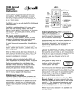
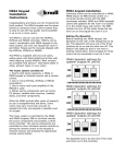
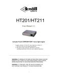
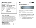
Specifications
MVP44a 8 Channel Power Amplifier
Inputs:
4 pairs of gold RCA jacks
Input impedance:
24 k ohms
Outputs:
Gold 5 way Binding posts
Output power:
50 watts RMS per channel (8 ohms)
Peak output power: 100 watts RMS per channel (8 ohms)
Ideal impedance: 6-8 ohms
Freq. response:
10 Hz - 40 kHz +/- 1 dB (1w)
S/N ratio:
over 105 dB A weighted 50 watts
THD distortion:
<0.1% 20 Hz to 20 kHz
IMD distortion
<0.01% 60 Hz 7 kHz 4:1 (SMPTE)
Trigger control:
12VDC output 60mA max.
Power:
750 watts 117 VAC
Dimensions:
17" x 3.5" x 10.5"
Weight:
22 lbs (10 kg)
Operating Temp:
-20C to +60C (-4F to +140F)
Caution: Never listen to sound that is distorted. If distorted sound
is heard, turn the volume down immediately or speaker
and/or amplifier damage could occur that is not covered by the
warranty. If this problem persists, contact your dealer.
Limited Warranty
Knöll Systems warrants the its electronic products except projectors sold in Canada and the
USA by authorized Knöll dealers to be free from defects in materials and workmanship. This
warranty extends for three full years from the date of purchase by the consumer. Any
products returned freight prepaid to Knöll Systems and found to be defective by Knöll
Systems within the warranty period will be repaired or replaced at Knöll Systems option, at
no charge. Knöll Systems will not be responsible for the actual cost of installation or removal
of the product, nor for any consequential or incidental damages. Some states do not allow the
exclusion or limitation of incidental or consequential damages, so the above limitation or
exclusion may not apply to you. This warranty gives you specific legal rights. You may have
additional rights which vary from state to state. Knöll products sold outside of Canada and
the USA may be covered by warranties provided by an authorized Knöll distributor. Please
contact the distributor in the country that the Knöll product was purchased.
Printed in Canada
Knöll Systems, Richmond, BC & Point Roberts WA
C COPYRIGHT 1998-2003, Knöll Systems, All Rights Reserved
Knöll Systems
tel (604) 272-4555
fax (604) 272-5595
In America:
145 Tyee Drive, #1206
Point Roberts, WA 98281
In Canada:
11791 Machrina Way #120
Richmond, B.C. V7A 4V3
systems
MVP44a
Four stereo power amplifiers with
individual volume control electronics
and four input source selection
INSTALLATION
MANUAL
It is very important to use a top quality
RJ45 8/8 crimper tool. We strongly
suggest using a cat 5 / RJ45 electronic
tester to verify the wire conductors.
Complies with part 15 of the FCC rules. Operation is subject to:
1. This device may not cause harmful interference
2. This device must accept any interference received
including interference that may cause undesired operation.
Version 3.3
Congratulations and thank you for choosing the Knöll
MVP44a power amplifier. The MVP44a is designed to meet
the amplifier needs of custom installed multi-zone systems
where high quality sound is a specific requirement as well
as ease of installation and operation. A six output zone
model is available, MVP64a.
Troubleshooting
Key Features:
1. Individual zone, four source selection. Each of the four rooms
Problem
Action
Power indicator does
not light - no sound
1. Check that the MVP44a is plugged in.
2. Test the AC outlet with a lamp..
3. Check that the MVP44a power button is
on (in).
Sound cuts out
1. Verify speaker impedance is 4-16 ohms.
Changing speakers may be required.
2. Check if the MVP44a feels hot. If it's
hot, increase cooling - see Installation.
Sound is distorted
1. Turn the volume down
2. Check speakers for damage.
3. Check inputs for proper levels.
Source output levels may need adjustment.
4. Speakers may have less than 4 ohm rating
5. If inputs are Y corded to another MVP44a
or stereo receiver, make sure all amps are
turned on or a MR24 buffer may be required.
MVP44a does not
turn off
1. Press any MR60 keypad "OFF" button or
RB8 remote "POWER" button for 5 seconds.
The MVP44a should power down and the
MVP44a led turns orange (standby). Before
turning the MVP44a power switch off (out)
we suggest that the MVP44a be in standby
Speaker pops when
amp turned on or off
1. Speaker may need resistor placed across
terminal. We suggest 2k0 1/4 w resistor
which discharges the speakers internal
capacitor.
can select any of the four stereo sources.
If a problem is encountered with the MVP44a, the most expedient
procedure is to locate the problem and if possible repair it before
requesting service. Be sure to carefully check other system
components such as controllers, CD players, volume controls, wiring,
speakers, etc. that may be at fault.
2. Individual mute, volume, bass, treble and balance adjustment.
Each of the four stereo channels feature adjustments for bass, treble and
balance. Individual room keypads control volume and mute. Any keypad
can turn the whole system on or off.
3. Cost and size efficiency. The MVP44a consists of a total of four
stereo power amplifiers with individual volume control electronics in a 31/2" enclosure. Each power amplifier channel can deliver 50 watts RMS.
4. Automatic protection circuitry. Each MVP44a channel is
individually and fully protected against low impedance, overheating,
overloading, overvoltage and undervoltage. The protection circuitry
automatically restores the amplifier channel as soon as its parameter
returns to the safe operating area.
5. External trigger and functions out. An 12VDC trigger output is
provided to turn other components on or off. Six function ports are
provided (connects to a 590-00) to turn on and off components via IR as
well as provide four IR commands, source from the MR60 keypads
6. Stackable 17" chassis. The MVP44a can be stacked or placed in a
19" EIA equipment rack (requires RK-AMP kit).
7. Data port. For larger systems, multiple MVP44a's can operate in
tandem so all MVP44's turn off and on together and share infrared
signals, page, connect to door chimes, connect to external controllers, etc.
8. Cooling fan. Fans maximize system performance and helps to avoid
early protection system distortion.
9. All on and all off. MR60 keypads turn on any source in all rooms.
10. Volume level indication. MR60 keypads display volume level on
top three rows of buttons. FNC-MUTE level is the lowest.
11. All room volume up and down (rooms on only) via FNC button.
2
15
possible in the sequence to give the components settling time. For
example, sequence a power-on command: CD on, tuner on, and CD
play rather than CD on, CD play, and tuner ON.
7. Make sure the PROGRAM lamp is on.
8. Make sure the bank 1 switch is on and bank 2, 3 and 4 are off.
9. Push the SEQ (sequence) button.
10. Carefully touch (for one sec.) the wire to the bank 1 + terminal
1 to 6 where the first sequence is to be stored.
11. Move the bank 1 switch off and the bank 2 switch on.
12. Touch the wire to the terminal where the first IR signal of the
sequence is stored (for one second). Touch the wire to the
terminal where the second IR signal of the sequence is stored
(for one second). Touch any other terminals until the entire
command sequence is stored.
13. Push the SEQ button and then the PGM button to leave the
program mode (lamp goes out).
14. Move the bank 1 switch to on and bank 2, 3, and 4 to off.
The sequence is now complete.
15. Repeat steps 7 to 14 for each of the other sequences.
Note: 590-00 programming should be fully tested. Occasionally one
source component gets out of sequence especially if IR remote
controls are used (most often when using the remote to turn on and
off source components). The system user should be shown how to
correct for a source component getting out of sequence.
System layout considerations
The MVP44a is the heart of a whole home music system. A MVP44a
is designed to work with 1-4 rooms or zones. Up to three MVP44a's
can be ganged together to allow up to 12 rooms or zones each
individually controlling one or two pairs of enclosure or inwall
speakers. Connection is achieved via the data port using a stereo
3.5mm jack on the rear of the MVP44a.
Rooms are usually controlled by a MR60 keypad. The keypads are
not intented for outdoor use. The MR60 contains an almost all
brand infrared repeater and most functions can be controlled by the
Knoll RB8 remote control. RB8 commands can easily be stored in a
learning remote. The MR60 is available with three different source
layouts (all of the MR60 keypads in one system have to have the
same source layout) and three bezel colors white, almond and ivory
for a total of 9 models. The source layout and bezel colors are easy to
change in the field.
Some rooms will not require a MR60 keypad and most MVP44a
functions can be utilized with an RB8 remote and an infrared
repeater (a MR173 IR converter is required). Up to three IR
receivers in three different rooms can be connected to a single
MR173. The MVP44a includes an internal four single or dual emitter
connection block, so emitters will have to be ordered if required. The
infrared pass through is always available when the amplifier is turned
on and in standby or powered up.
Follow directions from the speaker manufacturers when deciding
speaker locations.
Caution: The MVP44a contains no user serviceable parts, so
do not attempt to open or repair the MVP44a. Refer servicing to
a qualified technician only or contact the factory for information.
14
Note: The MVP44a prefers 6-8 ohm speaker loads. Connecting to
4 ohm loads won't hurt the MVP44a but those channels connected
to 4 ohm loads may occasionally shut down due to overloading.
Never connect the MVP44a to 2 ohm loads.
The MVP44a has a cooling fan to increase long term power output
and reliability.
...continued
3
...System layout considerations continued
In certain commercial applications a microphone paging override
is required. Model MR171 paging and override module takes a
balanced or unbalanced mic, (with defeatable phantom power) or
a line level input and when activated overrides all inputs (even if
some or all zones are in standby) and pages at a preset volume in
all zones.
A variety of door chime and telephone paging, door entry and
front door camera modules are being developed. Check our web
site for more information.
The MVP44a includes a 12VDC trigger output to control and power
various items when the MVP44a is powered up. When the MVP44a
agoes into standby the trigger output ends. It's maximum output is
60mA.
An innovative IR connection system is also included to turn on and
off the various source components as well as four separate
commands. A Xantech 590-00 controller is required for this
purpose. The Xantech 590-00 is a an IR sequence generator. When
it receives commands from the MVP44a it generates an IR command
or sequence of up to 10 commands.
The on command is automatically generated when the MVP44a goes
out of standby and into power up. The off command is automatically
generated when the MVP44a goes from power on to standby. These
sequences are generally used to turn on and off the source equipment.
To activate the four commands, when the system is powered up,
press the MR60 keypad button FNC then quickly press one of the
four source buttons on the top of the MR60 keypad. This will
initiate a pulse at the MVP44a FUNCTION output, that in turn
generates an IR command that is pumped back into the MVP44a IR
emitter port 1 and out to the various emitters connected to ports
2-3-4, that will initiate the command to the source component.
4
in bank 1 positions 1 through 6).
The 590-00 can learn up to 16 different commands on each of its
four banks. If more than 10 different IR commands are to be stored
use bank 2, 3, and 4 to store the sequence commands and bank one
positions 1-6 to execute the sequences.
1. Write down the order for each of the sequences required for all
of the six functions (not programmed with single commands).
2. Turn the bank 2 dip switch on; bank 1, 3, and 4 off.
3. Push PGM (program lamp goes on).
4. Using the wire attached to the 590-00 +12VDC, touch and
hold the other end of the wire to the 590-00 upper + row
terminal 1. While holding the wire in place, press the remote
control button of the first function while the remote is about
2-4" from the 590-00 internal infrared sensor. The 590-00
PROGRAM lamp will flicker while storing the IR signal.
When the IR signal is stored, the confirm lamp comes on.
Release the remote control button and release the wire to the
upper row terminal. The IR signal is now stored in the 590-00
bank 2 terminal 1.
5. Hold the end of the wire to the 590-00 upper + row terminal
2. While holding the wire in place, press the remote control
button of the second function while it is about 2-4 inches from
the 590-00 internal infrared sensor. The 590-00 PROGRAM
lamp will flicker while storing the information. When the
information is stored, the confirm lamp will come on. Release
the remote control button and release the wire to the upper
row terminal. The IR signal is now stored in the 590-00 bank 2
terminal 2.
6. Continue this procedure until all of the required sequence
commands have been learned by the 590-00. If more than 16
IR signals have to be learned, fill up bank 2 with the first 16
IR signals, then turn the bank 2 dip switch off, and the bank 3
switch on. Continue with bank 3 position 1, 2 etc. Use bank 4
positions 1, 2, etc., if required and bank 1 positions 7-16.
Note: When storing an IR signal command sequence, it is most
reliable if commands to a component are timed as far apart as
13
gather all the source remotes (with batteries inserted) near the 59000. Screw one end of a temporary wire to the 590-00 terminal
marked +12VDC. Power up the 590-00 and the MVP44a.
The 590-00 can learn up to 16 different commands on each of its
four banks. If more than 10 different IR commands are being stored
use bank 2, 3, and 4 to store the sequence commands and bank one
positions 1-6 to execute the sequences.
Single IR Command Storing
Start by pushing the RES (reset) button on the back of the
590-00. If any of the six relay activations have a single command
(not a sequence of commands), program the single command(s) first.
For example if the jazz station tuner is on source C and you want to
program the IR command "scan" (two or more news stations have
been programmed in the news station tuner) into function C, program
the 590-00 with this first.
1. Make sure the bank 1 dip switch is on; bank 2, 3, and 4 off.
2. Push PGM (program lamp goes on).
3. Using the wire attached to the 590-00 +12VDC, touch and
hold the other end of the wire to the 590-00 upper + row
terminal 2. While holding the wire in place, push the tuner
remote control button "scan" while it is about 2-4 inches from
the 590-00 internal infrared sensor. The 590-00 PROGRAM
lamp will flicker while storing the IR signal. When the IR signal
is stored, the confirm lamp comes on. Release the remote
control button and release the wire to the upper row terminal.
The IR signal is now stored in the 590-00 bank 1 terminal 2.
4. Store any other single commands in bank 1 positions 1 and 3-6.
5. Push PGM (program lamp will go out).
590-00 Sequence IR Command Storing
The six MVP44a pulse activations can activate a sequence of up to 10
IR commands each. As an overview, the individual IR commands
are first learned and stored in any of the 16 positions in the four
banks (except bank 1 positions 1 through 6), then assembled in order
12
Installation
It is very important to use a top quality RJ45 8/8 crimper
tool. We strongly suggest using a cat 5 / RJ45 electronic
tester to verify the wire conductors.
Installing the MVP44a should be relatively easy. With a bit of
planning, the MVP44a will give trouble free service for years.
1. The most important consideration when installing the
MVP44a is cooling. The MVP44a has a lot of power packed into a
small chassis size. When installing it in an equipment stack, it should
be the top component. It needs at least 1-3/4" of space above the
MVP44a to allow for adequate cooling.
2. When installing the MVP44a in a rack we suggest adding a
1-3/4" blank above and below the MVP44a. In multiple MVP44a
installations, plan for a 3-1/2" blank (double) between each MVP44a
and a 1-3/4" blank on the top and bottom. Amplifiers should
always be the top components in a rack system.
3. If MVP44a channels frequently shut down due to overheating,
either the output levels will have to go down or 8 ohm speakers
installed. If 8 ohm speakers are installed on all channels and some
channels still shut down, call the factory for advice.
4. Connect the MVP44a inputs to the source component outputs with
good quality, short as possible RCA jack cables. Connect each
channel individually.
5. If source D is not being used we suggest you short both of them
out with a RCA shorting jack. This will make the room speakers
quieter in standby modes.
6. Connect the MVP44a speaker outputs to speakers using good
quality speaker wire. Minimum 16 gauge copper wire is
recommended with 14 gauge minimum for runs over 30' (10m)
Make sure the speakers in each room are connected in phase.
Note: Ideally the MVP44a likes 6-8 ohm loads. Connecting to
4 ohm loads won't hurt the MVP44a but those channels
connected to 4 ohm loads may occasionally shut down due to
overloading. Never connect the MVP44a to 2 ohm loads.
5
7. Install MR60 keypads (or infrared receivers) in the rooms with
the speakers. Cat 3 or cat 5 wire can be home run to the MVP44a or
up to three rooms daisy chained on one wire.
***Be sure to set the dip switch on the rear of the MR60***
See the dip switch adjustment below. Connect all eight individual
wires using RJ45 connectors. Four wire conductors are needed for
each keypad (one unique, common: IR , ground and 12VDC).
MR60 Dip Switch
Adjustment
MR60 1 2 3 4
Use either RJ45
connector as they
are in parallel
The rear of the MR60 is shown. Because one to three MR60's can
be connected or daisy chained to the same cat 5 wire, the keypad
position on the wire must be selected using the dip switch. The two
MR60 RJ45 connectors are in parallel. Only one dip switch slider
should be on and the other two off (#1 is shown on in this example).
The MR60 1-2-3 dip switch positions correspond to MVP44a keypad
ports and speaker outputs A3 or B1-B2-B3.
***Even if the keypads are home run, the
MR60 dip switch position has to be selected***
If three keypads are daisy chained on one wire, select the MR60
dip switch on the first MR60 to one, the second MR60 to two and
the third MR60 to three. At the rear of the MVP44a, the RJ45
connector from the three MR60 keypads can be connected any
corresponding keypad Bank A3 or Bank B; port 1, 2 or 3. The
corresponding speaker outputs will be the same number as selected
on the MR60 keypad (example: the MR60 keypad with #2 dip on
and connected to MVP44a keypad bank B will control speaker
outputs B2R and B2L).
After installation, if the keypads are not working properly or not
controlling at all, Check the MR60 dip switch settings, wiring
layout and crimp as well as bank connections very carefully.
6
MVP44a Activation
The 590-00 generates infrared command sequences when a
momentary pulse from any of the six MVP44a function outputs are
activated. Source A is usually reserved for CD use. When the MVP44a
is powered up someone pushing a MR60 Source button or RB8
remote source, the power on (TON) pulse is activated.
Some examples to understand when MVP44a pulses are activated
and the 590-00 macro sequencies are initiated are listed below:
Note: None of the functions below work when any MR60 leds are
blinking to indicate MUTE activated.
Pulse O/P
Activates when:
Power On
(TON)
Any MR60 or RB8 source
key is pushed when all
MR60 leds are off.
FA
FNC then Source A (CD)
(source A
key pushed when system's on
CD player) and no MR60 blinking led's.
FB
FNC then Source B (FM or
(source B
AUX1) key pushed when
Jazz station) the system is on.
FC
FNC then Source C (Dish
(source C
AM or CD2) key pushed
news tuner) when the system is on.
FD
FNC then Source D (AUX or
(source D
AUX2) key pushed when
sat dish#2) the system is on.
Example IR sequence:
Sequence power (on)
command to all
source components
CD skip, CD play or
CD random
CD skip to next disk
Scan to next news
station programmed
into news tuner
Scan up one station
Programming the 590-00
IR functions do not have to be related to the source input. For
example, if source A is a CD player and source B is a jazz tuner,
function A could be a sequence of CD skip, CD play, and CD
random. Function B could be CD Skip to next disk. After deciding
and writing down the commands to be programmed for each of the
six pulse activations (Function A, B, C, D, TON and TOFF),
11
MVP44a to Xantech 590-00
The Xantech 590-00 is an infrared learning "remote" capable of
converting a dry contact closure of each of the MVP44a's four
functions, power-on (TON) and power-off (TOFF) to an IR
macro sequence of up to 10 commands each.
The 590-00 power supply is shipped with the 590-00. Power to
the 590-00 should be on all the time (like a TV set) so the system
IR commands can be sent as soon as any MR60 source buttons are
pressed.
The first time installing and programming a 590-00 connected to a
MVP44a can be a bit tricky, so please follow these directions closely.
See the diagram on page 7.
Connect the 590-00 rear panel "O" and "G" terminals to the wire pair
on the 3.5mm to wire pair (installer supplied). Connect the black wire
with the stripe to the "O". Next insert the 3.5mm plug into the rear of
the MVP44a labelled "IR Emitters" and "1".
8. Connect the emitters to the IR Emitter ports on the rear of the
MVP44a. Single or dual emitters can be used. If a Xantech 590-00 is
being installed do not connect emitters in the MVP44a IR Emitter #1.
9. When connecting two or more MVP44a's in the same home,
connect the amps together using stereo 3.5mm plugs (all three wires are
used) to the data plug on the rear of the MVP44a. The MVP44a's
share power on and off data as well as infrared signals.
The MVP44a source input RCA jacks are Y-corded
together on all amps (source 1 left/right on amp 1
to source 1 left/right on amp 2 etc.)
10. Connect the AC power into an outlet that can supply at least six
amps (700 watts) dedicated to each MVP44a.
11. If a Xantech 590-00 is to be installed, the 590-00 needs to be
wired to the MVP44a removable 8 terminal connector and the
590-00 has to be programmed.
With any type of single conductor wire connect the 590-00 bottom
row - terminals 1, 2, 3, 4, 5, 6 and the -12VDC terminal.
DO NOT connect any wires to the TRIG
terminal on the MVP44a at this time.
Now connect the MVP44a terminal FD to the 590-00 top row +
terminal 1. Next connect the MVP44a terminal FC to the 590-00 top
row + terminal 2.
Continue by individually connecting the MVP44a FB, FA, TOFF and
TON to the 590-00 top row + terminal 3, 4, 5 and 6. If all of the
source equipment has the same IR commands for power-on and
power-off, move the wire on the 590-00 connected to terminal +5
(on the + row) with the wire on the 590-00 terminal +6.
10
Wiring the 590-00 to the MVP44a
The wire/plug from the 590-00 IR emitter port 1 is a mono 3.5mm
with the stripewire to the center/end of the 3.5mm connector. The
rest of the wires can be almost any type.
7
MVP44a Rear Panel
Note 1: Ideal speaker impedance is 6-8
ohms. When using 4 ohm speakers,
individual channels may occasionally
shutdown due to protection system.
3
4
L
A3L+
A3L-
B1L-
B1L+
B2L+
B2L-
B3L-
B3L+
A3R+
A3R-
B1R-
B1R+
B2R+
B2R-
B3R-
B3R+
R
To Keypads
IR Emitters
4/in 3
2
1
Room A3 Room B1 Room B2 Room B3
Room A3
Room B1
Data
Treble Bass Balance Treble Bass Balance
Room B2
Room B3
Treble Bass Balance Treble Bass Balance
FD
FC
FB
FA
TOFF
TON
TRIG
GND
2
12345
12345
12345
12345
12345
12345
12345
Outputs
Outputs
Source Inputs
1
AC120V
8 amps
RJ45 plug function identification
MR60 keypad functions
Infrared receiver
Four source selection (this
room and whole house) and
four function selection buttons
1
2
3
4
FNC
MUTE
DN
UP
OFF
not
used
comm
3
ground
ground
12 VDC
infrared
comm
2
comm
1
Each RJ45 connector uses 4 wires from MR60
to MVP44a for power, communications and IR.
3 are common, 12VDC, GND (either) and IR.
1 is uniqure 2-way comm (1, 2 or 3)
Comm1 goes to keypad slot A1 or B1
Comm2 goes to keypad slot A2 or B2
Comm3 goes to keypad slot A3 or B3
Three bar volume level
indicators, blinks at min or max
Mute button
Function select button
Volume up and down
(this room only or whole
house when FNC selected)
Shut off this room only or
whole house off button
(also blinks when remote
control signal detected)
RJ45 plug color and pair wiring guide
comm 1 brown
white/brown
orange
white/blue
blue
white/orange
green
not used white/green