1
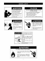
Use & Care Guide Model 0Qus No. 153.312420 40 Gallon I<enmore® c" For potable water @ heating only. Not suitable for space heating. INSTALLER: Affix these instructions to or near the water heater. OWNER: Retain these instructions for future reference. Si no puede leer o entender el ingles y necesita el manual de instrucciones en espaSol, puede solicitarlo al 1-800-821-2017. NO TRATE DE INSTALAR U OPERAR ESTE CALENTADOR DE AGUA SI NO ENTIENDE LAS INSTRUCCIONES. No hacer caso de esta advertencia podria originar lesiones graves o mortales. P/N 319358-000 Sears Brands (0710) Management Hoffman Estates, www. kenmore.com www.sears.com IL 60179 Corporation, U.S.A. Your safety and the safety of others is extremely important in the installation, use and servicing of this water heater. Many safety-related messages and instructions have been provided in this manual and on your own water heater to warn you and others of a potential injury hazard. Read and obey all safety messages and instructions throughout this manual. It is very important that the meaning of each safety message is understood by you and others who install, use or service this water heater. A This is the safety alert symbol. It is used to alert you to potential personal injury hazards. Obey all safety messages that follow this symbol to avoid possible injury or death. DANGER indicates an imminently hazardous situation which, if not avoided, will result in death or injury. WARNING indicates a potentially hazardous situation which, if not avoided, could result in death or injury. _ml!l'll CAUTION indicates a potentially hazardous situation which, if not avoided, could result in minor or moderate injury. CAUTION used without the safety alert symbol indicates a potentially hazardous situation which, if not avoided, could result in property damage. All safety messages will generally tell you about the type of hazard, what can happen if you do not follow the safety message and how to avoid the risk of injury. The California Safe Drinking Water and Toxic Enforcement Act requires the Governor of California to publish a list of substances known to the State of California to cause cancer, birth defects, or other reproductive harm, and requires businesses to warn of potential exposure to such substances. This product contains a chemical known to the State of California to cause cancer, birth defects, or other reproductive This appliance can cause low level exposure to some of the substances listed in the act. harm. IMPORTANT DEFINITIONS Sears Service Center: The Sears Service Center has the ability equivalent to a licensed tradesman in the fields of plumbing and electrical work including a thorough understanding of the requirements of the National Electrical Code as it relates to the installation of electric water heaters. The Sears Service Center also has a thorough understanding of this instruction manual, and is able to perform repairs strictly in accordance with the service guidelines provided by the manufacturer. © 2009 Sears Brands Management Corporation Readandunderstand instruction manual andsafetymessages before installing, operating or servicing thiswaterheater. Failure tofollowinstructions and safety messages couldresultin death orserious injury. Instruction manual mustremain withwaterheater. Explosion Improper installation and use may result in property damage. • Do not operate water heater if flood damaged. • Inspect and replace the anodeas needed. • Install in location with drainage. • Fill tank with water before operation. • Be alert for thermal expansion. Refer to instruction manual for installation and service. Hazard • Before removing any access panels or servicing the water heater, make sure the electrical supply to the water heater is turned "OFF". • Overheated water can cause watertank explosion. • Properly sized temperature and pressure relief valve must be installed in opening provided. • Failure to do this could result in death, serious bodily injury, or property damage. Water temperature over 125°F (52°C) can cause severe burns instantly resulting in severe injury or death. Children, the elderly, and the physically or mentally disabled are at highest riskfor scald injury. Feel water showering. before bathing or Temperature limiting valves are available. Read instruction manual for safe temperature setting. Fire Hazard / Electric Shock Hazard voltage other than shown on the model rating plate. _i_ • Failure to use the correct voltage shown rating plateheater could with resultany in • on Dothe notmodel use this water death, serious bodily injury, or property damage. 3 - YEAR LIMITED WARRANTY ON WATER HEATER For three years from the date of purchase, if this water heater is installed and operated in a single-family owner's manual instructions and all local applicable plumbing codes, Sears will: 1. Supply free water heater parts for those that are defective in material or workmanship. 2. Supply a free water heater for one that develops a leak. home in accordance with the For the second through third year from the purchase date, you must pay the labor cost for installation of parts or water heater. For commercial, institutional, industrial or residential use by two or more families, the above limited warranty is only for two years. During the second year you must pay the labor cost for parts or water heater installation. If governmental regulations prohibit Sears from furnishing a comparable model replacement water heater under this warranty, Sears will furnish a new water heater of comparable output as permitted by such governmental regulations; however, the Owner will be charged for the additional cost associated with the changes made to the replacement water heater design to comply with such governmental regulations. Replacements and/or repairs furnished under this warranty of the original warranty. 1 -YEAR do not carry a new warranty, and are only covered by the unexpired portion EXCLUSIVE KENMORE LABOR WARRANTY For the first year from the date of purchase, Sears will, free of charge, supply and install new water heater parts for defective ones or a new water heater for one that develops a leak. WARRANTY SERVICE To obtain warranty service, call 1-800-4-MY-HOME ® (1-800-469-4663). This warranty applies only while this product is in use in the United States. This warranty gives you specific legal rights, and you may also have other rights which vary from state to state. SEARS BRANDS MANAGEMENT The price of your water heater does not include warrants the installation. A charge will be made on service a. Adjusting Master a free checkup calls due to poor or incomplete thermostat Protection CORPORATION, b. Condensation service Hoffman Estates, IL 60179 call. On water heater installation. These installations arranged by Sears, Sears include: c. Leaks in pipes or fittings Agreements Congratulations on making a smart purchase. Your new Kenmore ® product is designed and manufactured for years of dependable operation. But like all products, it may require preventive maintenance or repair from time to time. That's when having a Master Protection Agreement can save you money and aggravation. The Master Protection Agreement also helps extend the life of your new product. Here's what the Agreement* includes: $250 Food Loss Protection is the result of mechanical or freezer. annually for any food spoilage that failure of any covered refrigerator • Rental reimbursement longer than promised. if repair of your covered product takes • 10% discount off the regular price of any non-covered service and related installed parts. repair • Parts and labor needed to help keep products operating properly under normal use, not just defects. Our coverage goes well beyond the product warranty. No deductibles, no functional failure excluded from coverage-real protection. Once you purchase the Agreement, a simple phone call is all that it takes for you to schedule service. You can call anytime day or night, or schedule a service appointment online. • Expert service by a force of more than 10,000 authorized Sears service technicians, which means someone you can trust will be working on your product. The Master Protection Agreement is a risk free purchase. If you cancel for any reason during the product warranty period, we will provide a full refund. Or, a prorated refund anytime after the product warranty period expires. Purchase your Master Protection Agreement today! • Unlimited service calls and nationwide you want us, whenever you want us. • "No-lemon" guarantee - replacement of your covered product if four or more product failures occur within twelve months. • Product • Annual Preventive extra charge. • Fast help by phone - we call it Rapid Resolution support from a Sears representative on all products. us as a "talking owner's manual." • Power power replacement if your covered Maintenance surge protection fluctuations. against service, product Check as often as and additional * Coverage in Canada varies on some items. For full details, call Sears Canada at 1-800-361-6665. can't be fixed. at your request - no electrical Some limitations and exclusions apply. For prices information in the U.S.A. call 1-800-827-6655. damage - phone Think of due to Sears Installation Service For Sears professional installation of home appliances, openers, water heaters, and other major home items, or Canada call 1-800-4-MY-HOME ®. garage door in the U.S.A. SAFE INSTALLATION, USE AND SERVICE ....................................................................................................................................... 2 GENERAL SAFETY ............................................................................................................................................................................. 3 PRODUCT WARRANTY ..................................................................................................................................................................... 4 TABLE OF CONTENTS ....................................................................................................................................................................... 4 INTRODUCTION 5 ................................................................................................................................................................................. PRODUCT SPECIFICATIONS ............................................................................................................................................................ MATERIALS AND BASIC TOOLS NEEDED ....................................................................................................................................... 5 6 Materials Needed .......................................................................................................................................................................... 6 Basic Tools .................................................................................................................................................................................... 6 Additional Tools Needed When Sweat Soldering ......................................................................................................................... INSTALLATION INSTRUCTIONS .................................................................................................................................................. Removing the Otd Water Heater ................................................................................................................................................ Facts to Consider About the Location ........................................................................................................................................... Insulation Blankets ........................................................................................................................................................................ Facts to Consider About the Convertible Lower Element .......................................................................................................... Water Piping ............................................................................................................................................................................ T & P Valve and Pipe Insulation .................................................................................................................................................. Temperature-Pressure Relief Valve ........................................................................................................................................ Filling the Water Heater .............................................................................................................................................................. 6 7-16 7,8 8 8 8,9 9,10 10 10,11 12 Converting the Lower Element .............................................................................................................................................. 12-14 Wiring .................................................................................................................................................................................... 14,15 Wiring Diagrams ......................................................................................................................................................................... SERVICE AND ADJUSTMENT .................................................................................................................................................... 16 17-22 Temperature Regulation ............................................................................................................................................................. 17 Thermostats ................................................................................................................................................................................ 17 Temperature Settings .................................................................................................................................................................. Lower Thermostat Adjustment ............................................................................................................................................... Anode Rod Inspection ................................................................................................................................................................ Temperature-Pressure Relief Valve Operation ........................................................................................................................... Draining and Flushing ............................................................................................................................................................ Thermostat Removal/Replacement Element Cleaning/Replacement ............................................................................................................................................ ............................................................................................................................................ 17 17,18 18 18 18,19 19 19-22 Drain Valve Washer Replacement .............................................................................................................................................. 22 Service ........................................................................................................................................................................................ 22 TROUBLESHOOTING Start Up Conditions GUIDE ..................................................................................................................................................... 23-25 ................................................................................................................................................................... 23 Thermal Expansion ............................................................................................................................................................. 23 Strange Sounds .................................................................................................................................................................. 23 Operational Conditions .......................................................................................................................................................... 23-25 Smelly Water ................................................................................................................................................................... 23,24 "Air" in Hot Water Faucets .................................................................................................................................................. 24 Rumbling Noise ................................................................................................................................................................... 24 High Temperature Shut Off System ..................................................................................................................................... 24 Not Enough or No Hot Water .......................................................................................................................................... Water Is Too Hot .................................................................................................................................................................. 24,25 25 Leakage Checkpoints ................................................................................................................................................................. REPAIR PARTS LIST ................................................................................................................................................................... 26 27-29 NOTES ......................................................................................................................................................................................... 30,31 WARRANTY ...................................................................................................................................................................................... 32 installed andmaintained, itshould giveyouyearsoftrouble free service. Itisstrongly suggested thatthisnewwaterheater be professionally installed, contact thelocalSears Service Center or anySears store.Theywiltarrange forprompt, quality installation bySearsauthorized contractors. manual; electric company rules; and Local Codes, or in the absence of Local Codes, with the current edition of the NEC - National Electrical Code, NFPA 70. This publication is available from your local government or public library or electric company or by writing Underwriters Laboratories Inc., 333 Pfingsten Road, Northbrook, IL 60062. Abbreviations If after reading this manual you have any questions or do not understand any portion of the instructions, call Sears Service Center. UL- Found In This Instruction Manual: Underwriters Laboratories Inc. Carefully plan the place where you are going to put the water heater. Correct electrical wiring and connections are very important in preventing death from possible electrical shock and fires. NEC - National Electrical Code ANSI-American National Standards Institute Read the General Safety section, page 3 of this manual first and then the entire manual carefully. If you don't follow the safety rules, the water heater will not operate properly. It could cause DEATH, SERIOUS BODILY INJURY AND/OR PROPERTY DAMAGE. This manual contains instructions for the installation, operation, and maintenance of this electric water heater. It also contains warnings throughout the manual that you must read and be aware of. All warnings and all instructions are essential to the proper operation of the water heater and your safety. Since we cannot put everything on the first few pages, READ THIS ENTIRE MANUAL BEFORE ATTEMPTING TO INSTALL OR OPERATE THE WATER HEATER. Examine the location to ensure the water heater complies with the Facts to Consider About the Location section. For California installation, this water heater must be braced, anchored, or strapped to avoid falling or moving during an earthquake. See instructions for correct installation procedures. Instructions may be obtained from California's Office of the State Architect, 1102 Q Street, Suite 5100, Sacramento, CA 95811. Instructions can also be downloaded to your computer at www.dsa.dgs.ca.gov/Pubs. Massachusetts Code requires this water heater to be installed in accordance with Massachusetts 248-CMR 2.00; State Plumbing Code and 248-CMR 5.00. In the Commonwealth of Massachusetts, this product must be installed by a licensed plumber or gasfitter. MAXIMUM DIMENSIONS IN INCHES (mm) RECOVERY RATE GALS. PER HOUR ELEMENT WATTAGE MINIMUM WIRE FUSE OR CIRCUIT BREAKER SIZE SIZE* (GAUGE) (AMPS) MODEL TANK CAPACITY NUMBER IN GALLONS DIA. HEIGHT @ 90°F RISE @ 240 VOLTS 153.332420 40 20.5 (521) 44.0 (1118) 17.3 3800 12 20 * Wiring size based on standard 60°C copper wire. If distance from fuse box to water heater is more than 90 feet, refer to your local electrical code. Materials Needed To simplify the installation Sears has available the installation parts shown below. You may or may not need all of these materials, depending on your type of installation. EXPANSION EXPANSION TANKS FOR THERMAL CONDITIONS AVAILABLE IN 2 GALLONS , AND 5 GALLONS CAPACITY THROUGH LOCAL SEARS STORE OR SERVICE CENTER. METAL DRAIN PANS AVAILABLE IN 20" DIAMETER FOR WATER HEATERS HAVING A DIAMETER 18" OR LESS AND IN 24" DIAMETER FOR WATER HEATERS HAVING A DIAMETER OF 22" OR LESS. WATER HEATER INSTALLATION KIT WITH FLEXIBLE CONNECTORS FOR 3/4" THREADED OR COPPER PLUMBING. Basic Tools Additional You may or may not need all of these tools, depending on your type of installation. These tools can be purchased at your local Sears store. Pipe Wrench (2) Screwdriver 6 Foot Tape or Folding Rule Garden Hose Drill Pipe Dope or Teflon Tape _L. _ Ill} Tools Needed When Sweat Soldering Tubing Cutters or Hacksaw Propane Torch Soft Solder Solder Flux Emery Cloth Wire Brushes TUBING CUTTER DRILL SLOT-HEAD ROLL OF TEFLON TAPE (USE ON WATER CONNECTIONS) SCREWDRIVER \ HACKSAW B J PHILLIPS SCREWDRIVER i PIPE DOPE (SQUEEZE TUBE) USE FOR WATER CONNECTIONS ROLL OF EMERY CLOTH ROLL OF LEAD-FREE SOFT SOLDER 3/4" (19 mm)WIRE GARDEN HOSE 6 FOOT TAPE PIPE WRENCH PROPANE TORCH BRUSH C>-===, 1/2" (13 mm)WIRE BRUSH SOLDER FLUX Removing the Old Water Heater The water passing out of the drain valve may be extremely hot. To avoid being scalded, make sure all connections are tight and that the water flow is directed away from any person. 4, Check again to make sure the electrical supply is turned "OFF" to the water heater. Then unplug the water heater (cord set) or disconnect the electrical supply connection from the water heater junction box. FIGURE 4. 5a, 1. Turn "OFF" electrical supply to the water heater. If you have copper piping to the water heater, the two copper water pipes can be cut with a hacksaw approximately four inches away from where they connect to the water heater. This wilt avoid cutting off the pipes too short. Additional cuts can be made later if necessary. Disconnect the temperaturepressure relief valve drain line. When the water heater is drained, disconnect the hose from the drain valve. Close the drain valve. The water heater is now completely disconnected and ready to be removed. FIGURE 1. 2. Open a nearby hot water faucet until the water is no longer hot. When the water has cooled, turn "OFF" the water supply to the water heater at the water shut-off valve or water meter. FIGURE 5a. FIGURE 2. 3. Attach a hose to the water heater drain valve and put the other end in a floor drain or outdoors. Open the water drain valve. Open a nearby hot water faucet which will relieve pressure in the water heater and speed draining. FIGURE 3. 5b. If you have galvanized pipe to the water heater, loosen the two galvanized pipes with a pipe wrench at the union in each line. Also disconnect the piping remaining to the water heater. These pieces should be saved since they may be needed when reconnecting the new water heater. Disconnect the temperature-pressure relief valve drain line. When the water heater is drained, disconnect the hose from the drain valve. Close the drain valve. The water heater is now completely disconnected and ready to be removed. • Burn hazard • Hotwater discharge. • Keep hands clear of drain valve discharge. FIGURE 5b. • Sensors mounted in the metal drain pan that turn off the water supply to the entire home when water is detected in the drain pan. Mineral Buildup orSediment MayAccumulate • This causes the water heater to become much heavier than normal. • If spilled, could causestaining. • Water supply shut-off devices that activate based on the water pressure differential between the cold water and hot water pipes connected to the water heater. Mineral buildup or sediment may have accumulated in the old water heater. This causes the water heater to be much heavier than normal and this residue, if spilled out, could cause staining. Facts to Consider Installations • Water heater protective in Residential must be Garages located in a area. About the Location You should carefully choose an indoor location for the new water heater, because the placement is a very important consideration for the safety of the occupants in the building and for the most economical use of the appliance. This water heater is not intended for outdoor installation. INSTALLATION IN RESIDENTIAL GARAGES: The water heater must be located and/or protected so it is not subject to physical damage by a moving vehicle. • The location selection must provide adequate clearances for servicing and proper operation of the water heater. Insulation Whether replacing an old water heater or putting the water heater in a new location, the following critical points must be observed. The location selected should be indoors as close to and as centralized with the water piping system as possible. This water heater, as welt as all water heaters, wilt eventually leak. Do not install without adequate drainage provisions so water flow will not cause damage. Blankets Insulation blankets are available to the general public for external use on electric water heaters but are not necessary with this product. The purpose of an insulation blanket is to reduce the standby heat loss encountered with storage tank heaters. Your water heater meets or exceeds the National Appliance Energy Conversation Act standards with respect to insulation and standby loss requirements, making an insulation blanket unnecessary. Should you choose to apply an insulation blanket to this heater, you should follow these instructions below. Failure to follow these instructions can result in fire, serious personal injury, or death. Property Damage Hazard • Do not cover the temperature and pressure relief (T & P) valve with an insulation blanket. • Do not cover the instruction manual. Keep it on the side of the water heater or nearby for future reference. • D__go obtain new warning and instruction labels for placement on the blanket directly over the existing labels. • All water heaters eventually leak • Do not install without adequate drainage. WATER HEATERS EVENTUALLY LEAK: Installation of the water heater must be accomplished in such a manner that if the tank or any connections should leak, the flow of water wilt not cause damage to the structure. When such locations cannot be avoided, a suitable metal drain pan should be installed under the water heater. Drain pans are available at your local Sears stores. Such drain pans must be piped to an adequate drain. Water heater life depends upon water quality, water pressure and the environment in which the water heater is installed. Water heaters are sometimes installed in locations where leakage may result in property damage, even with the use of a metal drain pan piped to a drain. However, unanticipated damage can be reduced or prevented by a leak detector or water shut-off device used in conjunction with a piped metal drain pan. These devices are available from some plumbing supply wholesalers and retailers, and detect and react to leakage in various ways: • Sensors mounted inthe metal drain pan thattriggeran alarm orturn offthe incoming water tothewater heaterwhen leakage is detected. Water Piping Water temperature over 125°F (52°C) can cause severe burns instantly resulting in severe injury or death. Children, the elderly, and the physically or mentally disabled are at highest riskfor scald injury. Feel water showering. before bathing Temperature available. limiting valves or are Read instruction manual for safe temperature setting. HOTTER WATER CANSCALD: Waterheatersareintended to produce hotwater.Waterheatedto a temperature which wiltsatisfy clothes washing, dishwashing, andothersanitizing needs canscaldandpermanently injure youuponcontact. Some people aremorelikelytobepermanently injured byhotwater thanothers.Theseinclude theelderly, children, theinfirm,or physically/mentally handicapped. If anyone usinghotwaterin yourhomefitsintooneofthesegroups orifthereisalocalcode orstatelawrequiring acertain temperature wateratthehotwater tap,thenyoumusttakespecial precautions. Inaddition tousing thelowest possible temperature settingthatsatisfies yourhot waterneeds, ameans suchasamixing valveshould beusedat thehotwatertapsusedbythesepeople oratthewaterheater. Mixingvalvesareavailable atplumbing supplyor hardware stores. Followmanufacturers instructions forinstallation ofthe valves. Beforechanging thefactorysetting onthethermostat, readtheTemperature Regulation section in this manual. NOTE: To protect against untimely corrosion of hot and cold water fittings, it is strongly recommended that di-electric unions or couplings be installed on this water heater when connected to copper pipe. 1. Look at the top cover of the water heater. The hot water outlet is marked hot. Put two or three turns of teflon tape around the threaded end of the threaded-to-sweat coupling and around both ends of the 3/4" threaded nipple. Using flexible connectors, connect the hot water pipe to the hot water outlet of the water heater. 2. Look at the top cover of the water heater. The cold water inlet is marked cold. Put two or three turns of teflon tape around the threaded end of the threaded-to-sweat coupling and around both ends of the 3/4" threaded nipple. Using flexible connectors, connect the cold water pipe to the cold water inlet of the water heater. NOTE: Your water heater is insulated to minimize heat loss from the tank. Further reduction in heat loss can be accomplished by insulating the hot water lines from the water heater. See Figure 7 (below) for mixing valve usage. t HOT WATER OUTLET <[_ HOT COLD WATER INLET COLD 41_ <1_ HOT \ COLD TEMPEREE WATER OUTLET TO f FROM *MIXING VALVE WATER WATER INLET HEATER ON TEMPERATUREPRESSURE RELIEF VALVE HOT WATER OUTLET WATER _ COLD ON HEATER FIGURE 7. DISCHARGE PIPE (Do not cap or plug) Figure 8 shows the attachment of the water piping to the water heater. The water heater is equipped with 3/4" water connections. Ifa water heater is installed in a closed water supply system; such as one having a back-flow preventer, check valve, water meter with a check valve, etc.., in the cold water supply; means must be provided to control thermal expansion. Contact the local utility or Sears Service Center on how to control this situation. NOTE: If using copper tubing, solder tubing to an adapter before attaching the adapter to the water inlet connection. Do not solder the water supply lines directly to the cold water inlet. It will harm the dip tube and damage the tank. 6 INCH AIRMAXIMUM GAP FIGURE 8. T & P Valve and Pipe Insulation Property Damage 1. Locate the temperature and pressure relief valve on the water heater (also known as a T&P relief valve). See Figure 9. Hazard • Avoid water heater damage. 2. Locate the slit running the length of the T&P relief valve insulation. • Install thermal expansion tank if necessary. • Do not apply heat to cold water inlet. 3. Spread the slit open and fit the insulation over the T&P relief valve. See Figure 9. Apply gentle pressure to the insulation to ensure that it is fully seated on the T&P Relief Valve. Once seated, secure the insulation with duct tape, electrical tape, or equivalent. IMPORTANT: The insulation and tape must not • Contact qualified installer or service agency. 10 blockthedischarge opening orhinder access tothemanual relieflever(Figure 9). Ensure adischarge pipeisinstalled intotheT&Pvalvedischarge opening pertheinstructions in thismanual. 4. Locate thehotwater(outlet) &coldwater(inlet)pipestothe waterheater. 5. Locatetheslit runningthelengthof a sectionof pipe insulation. 6. Spreadtheslitopenandsliptheinsulation overthecold water(inlet)pipe.Applygentlepressure alongthelength of theinsulation toensure thatitisfullyseated around thepipe. Also,ensure thatthebaseoftheinsulation isflushwiththe waterheater.Onceseated, secure theinsulation withduct tape,electrical tape,orequivalent. 7. Repeat steps5 and6 forthehotwater(outlet) pipe. 8. Addadditional sections ofpipeinsulation asneeded. Thevalvemustbemarked withamaximum setpressure notto exceedthemarked hydrostatic working pressure ofthewater heater (150psi=1,035kPa)andadischarge capacity nottess thanthewaterheaterinputrateasshownonthemodelrating plate.(Forelectric heaters, wattsx 3.412equalsBtu/hrinput rate) Forsafeoperation ofthewaterheater, thereliefvalvemustnot beremoved fromitsdesignated opening norplugged. Thetemperature-pressure reliefvalvemustbeinstalled directly intothefittingofthewaterheater designed forthereliefvalve. Position thevalvedownward andprovide tubingsothatany discharge willexitonlywithin6inches (153mm)above, oratany distance belowthestructural floor.Becertain thatnocontact is made withanyliveelectrical part.Thedischarge opening must notbeblocked or reduced insizeunderanycircumstances. Excessive length, over30feet(9.14m),or useof morethan fourelbowscancauserestriction andreducethedischarge capacity ofthevalve. T&PRelief Valve Insulation Water Damage efLever • Temperature-pressure pipe must terminate relief valve discharge at adequate drain. No valve or other obstruction is to be placed between the relief valve and the tank. Do not connect tubing directly to discharge drain unless a 6 inch air gap is provided. To prevent bodily injury, hazard to life, or property damage, the relief valve must be allowed to discharge water in quantities should circumstances demand. If the discharge pipe is not connected to a drain or other suitable means, the water flow may cause property damage. Relief Valve Drain Line FIGURE 9. Temperature-Pressure Hazard Relief Valve The Discharge Pipe: • Explosion • • Hazard • Temperature-pressure relief valve must comply with ANSI Z21.22 CSA 4.4 andASME code. • • Properly sized temperature-relief valve must be installed in opening provided. • Can result in overheating excessive tank pressure. and Shall not be smaller in size than the outlet pipe size of the valve, or have any reducing couplings or other restrictions. Shall not be plugged or blocked. Shall be of material listed for hot water distribution. Shall be installed so as to allow complete drainage of both the temperature-pressure relief valve, and the discharge pipe. Shall terminate a maximum of six inches above a floor drain or external to the building. In cold climates, it is recommended that the discharge pipe be terminated at an adequate drain inside the building. Shall not have any valve between the relief valve and tank. ITs5D7.,1[€]:l • Can cause serious injury or death. This heater is provided with a properly certified combination temperature - pressure relief valve by the manufacturer. Water temperature over 125°F (52°C) can cause severe burns instantly resulting in severe injury or death. Children, the elderly, and the physically or mentally disabled are at highest riskfor scald injury. The valve is certified by a nationally recognized testing laboratory that maintains periodic inspection of production of listed equipment of materials as meeting the requirements for Relief Valves for Hot Water Supply Systems, ANSI Z21.22 • CSA 4.4, and the code requirements of ASME. If replaced, the valve must meet the requirements of local codes, but not less than a combination temperature and pressure relief valve certified as indicated in the above paragraph. Feel water showering. before bathing Temperature available. limiting valves or are Read instruction manual for safe temperature setting. 11 The temperature-pressure relief valve must be manually operated at least once a year. Caution should be taken to ensure that (1) no one is in front of or around the outlet of the temperaturepressure relief valve discharge line, and (2) the water manually discharged wilt not cause any bodily injury or property damage because the water may be extremely hot. If after manually operating the valve, it fails to completely reset and continues to release water, immediately close the cold water inlet to the water heater, follow the draining instructions, and replace the temperature-pressure relief valve with a new one. HOT Wiring You must provide all wiring of the proper size outside of the water heater. You must obey local codes and electric company requirements when you install this wiring. If you are not familiar with electric codes and practices, or if you have any doubt, even the slightest doubt, in your ability to connect the wiring to this water heater, obtain the service of a competent electrician. Contact your Sears salesperson to arrange for a professional electrician. WATER HEATERS EQUIPPED FOR ONE VOLTAGE ONLY: This water heater is equipped for one type voltage only. Check the rating plate near the bottom access panel for the correct voltage. DO NOT use this water heater with any voltage other than the one shown on the model rating plate. Failure to use the correct voltage can cause problems which can result in DEATH, SERIOUS BODILY INJURY, OR PROPERTY DAMAGE. If you have any questions or doubts consult your electric company. COLD HOT COLD TEMPERATUREPRESSURE J RELIEF VALVE -- DISCHARGE Fire Hazard / Electric PIPE Shock Hazard (Do not cap or plug) • Failure to use the correct voltage shown on the model rating plate could result in death, serious bodily injury, or property damage. I FLOOR Do not use this water heater with any voltage other than shown on the model rating plate. DRAIN_ FIGURE 10. Filling the Water Heater Property Damage If wiring from your fuse box or circuit breaker box was aluminum for your old water heater, replace it with copper wire. If you wish to reuse the existing aluminum wire, have the connection at the water heater made by a competent electrician. Contact your Sears salesperson to arrange for a professional electrician. Hazard • Avoid water heater damage. • Fill tan kwith water before operating. 1. Provide a way to easily shut off the electric power when working on the water heater. This could be with a circuit breaker or fuse block in the entrance box or a separate disconnect switch. Never use this water heater unless it is completely full of water. To prevent damage to the tank and heating element, the tank must be filled with water. Water must flow from the hot water faucet before turning "ON" power. To fill the water heater with water: 2. Install and connect a circuit directly from the main fuse or circuit breaker box. This circuit must be the right size and have its own fuse or circuit breaker. Refer to the chart in the Product Specifications section for the correct size wire and fuse or circuit breaker. 1. Close the water heater drain valve by turning the handle to the right (clockwise). The drain valve is located on the lower front of the water heater. 3. If metal conduit is used for the grounding conductor: 2. Open the cold water supply valve to the water heater. a, The grounding electrode conductor shall be of copper, aluminum, or copperctad aluminum. The material shall be of one continuous length without a splice or joint. b, Rigid metal conduit, intermediate metal conduit, or electrical metallic tubing may be used for the grounding means if conduit or tubing is terminated in fittings approved for grounding. NOTE: The cold water supply valve must be left open when the water heater is in use. 3. To ensure complete filling of the tank, allow air to exit by opening the nearest hot water faucet. Allow water to run until a constant flow is obtained. This will let air out of the water heater and the piping. 4. Check all new water piping for leaks. Repair as needed. 12 c. Flexible metal conduit or flexible metallic tubing shall be permitted for grounding if all the following conditions are met: The length in any ground exceed 6 feet. return path does Wiring Diagram not The circuit conductors contained therein are protected by overcurrent devices rated at 20 amperes or less. • Before removing any access panels or servicing the water heater, make sure the electrical supply to the water heater is turned "OFF". The conduit or tubing is terminated in fittings approved for grounding. For complete grounding details and all allowable exceptions, refer to the current edition of the NEC- National Electrical Code NFPA 70. • Failure to do this could result in death, serious bodily injury, or property damage. 4. Astandard 1/2" conduit opening has been made in the water heater junction box for the conduit connection. 5. Wiring Diagrams (see Wiring Diagrams section) have been supplied showing the two most common types of connections between the water heater and the power supply. You can easily see which type connection you have by removing the junction box cover on top of the water heater. • • STANDARD WIRING FOR 2 WIRE LEAD WATER HEATERS 240 VOLT SINGLE ELEMENT TO ELECTRIC POWER SUPPLY Two Wire Connection Diagrams: is the most common requiring you to simply connect red to red, black to black, and the ground wire to the green ground screw in the junction box of the water heater. JUNCTION BOX Three Wire Connection Diagram: is used when you are connecting the water heater to a power supply that has a "Time Clock" or "Off Peak" meter. To make these connections refer to block 1 or 2 in this wiring diagram for the type of system you have. BLACK RE NOTE: If you have purchased a three wire connection water heater but you are not on a "Time Clock" or "Off Peak" meter and have a standard two wire connection power supply, simply follow the connection diagram in block 3 of the three wire connection diagram. 1 _ 3 6. Use wire nuts and connect the power supply wiring to the wires inside the water heater's junction box. 7. The water heater must be electrically "grounded" by the installer. A green ground screw has been provided on the water heater's junction box. Connect ground wire to this location. @ o 8. Replace the wiring junction cover using the screw provided. _0 4 ,,, pTO_120480VAC2_220_72_0AVcAC o ,J m CONDUIT "__HEAT LOWER GREEN GROUND SCREW ING ELEMENT FIGURE 24. FIGURE 23. 13 Temperature Regulation IF llmT_,l([e] =1:! Temperature ,_ ...-'_@:k NOTE: Water temperature range of 120°m140°F (49°-60°C) recommended by most dishwasher manufacturers. Water temperature over 125°F (52°C) can cause severe burns instantly resulting in severe injury or death. Children, the elderly, Settings and the physically or mentally disabled Feel water before bathing or showering. _ Temperature limiting valves are available. are at highest riskfor scald injury. Read instruction manual for safe ,,. temperature setting. HOTTER WATER CAN SCALD: Water heaters are intended to produce hot water. Water heated to a temperature which wilt satisfy clothes washing, dish washing, and other sanitizing needs can scald and permanently injure you upon contact. Some people are more likely to be permanently injured by hot water than others. These include the elderly, children, the infirm, or physically/mentally handicapped. If anyone using hot water in your home fits into one of these groups or if there is a local code or state law requiring a certain temperature water at the hot water tap, then you must take special precautions. In addition to using the lowest possible temperature setting that satisfies your hot water needs, some type of tempering device, such as a mixing valve, should be used at the hot water taps used by these people or at the water heater. Mixing valves are available at plumbing supply or hardware stores. Follow manufacturers instructions for installation of the valves, Before changing the factory setting of the thermostat see Temperature Settings table at right. Never allow small children to use a hot water tap, or to draw their own bath water. Never leave a child or handicapped person unattended in a bathtub or shower. 110 116 116 122 (normalshowertemp.) (pain threshold) 35 minutes 1 minute 45 minutes 5 minutes 131 140 5 seconds 2 seconds 25 seconds 5 seconds 149 154 1 second instantaneous 2 seconds 1 second (U.S. Government Memorandum, Thermostat C.P.S.C., Peter L Armstrong, Sept. 15,1978) Adjustments Refer to thermostat illustrations under Thermostats section) • Before removing any access panels or servicing the water heater, make sure the electrical supply to the water heater is turned "OFF". • Failure to do this could result in death, serious bodily injury, or property damage. Thermostats The thermostat is adjustable if a different water temperature is desired, Read all warnings in the Temperature-Regulation section before proceeding, The thermostat of this water heater has been factory set at a position which approximates 120°F (49°C), to reduce the risk of scald injury. The thermostat is factory set at a position which approximates 120°F (49°C), and is adjustable if a different water temperature is desired. Read all warnings in this manual and on the water heating before proceeding. 1. Turn "OFF" the electric power to the water heater at the junction box. 2. Take off the access panel, then fold the insulation back to expose the thermostat. m 3. The slotted adjustment (using a screwdriver) can be turned clockwise ( t_ ) to increase the temperature setting or counter clockwise ((_) to decrease the temperature setting. -- 4. Replace the insulation and access panel. Hw o 4 5. Turn "ON" the power supply. @ FIGURE 27. 14 Anode Rod Inspection TEMPERATURE-PRESSURE RELIEF Property Damage VALVE Hazard • Avoid water heater damage. DISCHARGE • Inspection and replacement of anode as needed. PIPE FIGURE 28B. If after manually operating the valve, it fails to completely reset and continues to release water, immediately close the cold water inlet to the water heater, follow the draining instructions, and replace the temperature-pressure relief valve with a new one. The anode rod is used to protect the tank from corrosion. Most hot water tanks are equipped with an anode rod. The submerged rod sacrifices itself to protect the tank. Instead of corroding the tank, water ions attack and eat away the anode rod. This does not affect the water's taste or color. The rod must be maintained condition. Exposed Support Wire Failure to install and maintain a new properly listed temperaturepressure relief valve wilt release the manufacturer from any claim which might result from excessive temperature or pressure. to keep the tank in operating Pitted Anode Rod If the temperature-pressure relief valve on the appliance weeps or discharges periodically, this may be due to thermal expansion. Your water heater may have a check valve installed in the water line or a water meter with a check valve. Consult your local Sears Service Center for further information. Do not plug the temperature-pressure relief valve. Exposed Support Wire Draining and Flushing Ir 1 e7_,I[€')=1ti FIGURE 28A. Anode deterioration depends on the water conductivity, not necessarily water condition. A corroded or pitted anode rod indicates high water conductivity and should be checked and/ or replaced more often than an anode rod that appears to be intact. Replacement of a depleted anode rod can extend the life of your water heater. Inspection should be conducted by calling Sears Service Center. At a minimum the anode(s) should be checked annually after the warranty period. Temperature-Pressure The temperature-pressure at least once a year. eY_,1It1 =1tl • Burn hazard • Hotwater discharge. • Keep hands clear of drain valve discharge. The water heater should be drained if being shut down during freezing temperatures. Also, periodic draining and cleaning of sediment from the tank may be necessary. Relief Valve Operation relief valve must be manually operated • Before removing any access panels or servicing the water heater, make sure the electrical supply to the water heater is turned "OFF". • Burn hazard • Hotwater discharge. • Failure to do this could result in death, serious bodily injury, or property damage. • Keep hands clear of drain valve discharge. The temperature-pressure relief valve must be manually operated at least once a year. Caution should be taken to ensure that (1) no one is in front of or around the outlet of the temperaturepressure relief valve discharge line, and (2) the water manually discharged wilt not cause any property damage or bodily injury. The water may be extremely hot. 1. Before beginning, turn "OFF" the electric power supply to the water heater. 2. Open a nearby hot water faucet until the water is no longer hot. 3. Close the cold water inlet valve. 4. Connect a hose to the drain valve and terminate it to an adequate drain or external to the building. 5. Open the water heater drain valve and allow all of the water to drain from the tank. Flush the tank with water as needed to remove sediment. 15 NOTE: If the water heater is going to be shut down and drained for an extended period, the drain valve should be left open with hose connected allowing water to terminate to an adequate drain. NOTE: Some of the terminals may require straight-in wiring through an eye-opening. If wires are now looped, recut and strip wire 3/8" to a straight length and insert. 8. Put plastic terminal cover back in place. 6. Close the drain valve, refill the tank, and restart the heater as directed in this manual. 9. Replace the insulation to cover the thermostat. 10. Replace access panel, then turn the electric power on. Element Improper NOTE: These instructions are written for element cleaning and element replacement. installation and use may result in property damage. To remove replace it: • Fill tank with water before operation. Never use this water heater unless it is completely full of water. To prevent damage to the tank and heating element, the tank must be filled with water. Water must flow from the hot water faucet before turning "ON" power. Thermostat Cleaning/Replacement the element from your tank in order to clean or • Before removing any access panels or servicing the water heater, make sure the electrical supply to the water heater is turned "OFF". Removal/Replacement • Failure to do this could result in death, serious bodily injury, or property damage. • Before removing any access panels or servicing the water heater, make sure the electrical supply to the water heater is turned "OFF". 1. • Failure to do this could result in death, serious bodily injury, or property damage. Before beginning, turn "OFF" the electric power supply to the water heater. After the power has been turned off, open a nearby hot water faucet until the water is no longer hot. 1. Turn "OFF" the electrical power to the water heater at the junction box. 2. Remove the access panel, then fold the insulation back to expose the thermostat. 3. Lift out the tab as shown below to unctip the terminal cover from the thermostat. The terminal cover can now be removed from the thermostat. LIFT OUT TAB TO UNCLIP TERMINAL COVER FROM TH ERMOSTAT FIGURE 30. 2, JACKET TERMINAL COVER CLIPPED TO THIS POINT PLASTIC Turn off the water supply to the water heater at the water Shut-off valve or water meter. TABS ON BOTH SIDES OF TERMINAL COVER HOL IT IN PLACE BRACKET LOWER THERMOSTAT 3, ELEMENT JACKET FIGURE 31. Attach a hose to the water heater drain valve and put the other end in a floor drain or outdoors. Open the water heater drain valve. Open a nearby hot water faucet which will relieve pressure in the water heater and speed draining. FIGURE 29. 4. 5. Disconnect wires from the thermostat. Remove the thermostat from behind bracket. 6. Place the new thermostat in the bracket making sure it fits firmly against the tank. Attach the wires to the new thermostat. 7. the thermostat FIGURE 32. 16 eT_,W =1t,i • Burn hazard • Hotwater discharge. • Keep hands clear of drain valve discharge. FIGURE 36. The water passing out of the drain valve may be extremely hot. To avoid being scalded, make sure all connections are tight and that the water flow is directed away from any person. 4. 8. Clean the area around the element opening. Remove any sediment from or around the element opening, inside the tank. g. If you are cleaning the element you have removed, do so by scraping or soaking in vinegar or a de-liming solution. Remove the screw securing the access panel, then remove the panel. Fire Hazard Electric Shock " and Hazard • Do not use replacement elements with any voltage other than shown on the model rating plate. 5. Failure to use the correct voltage shown on the model rating plate could result in FIGURE 33. Fold the insulation back to expose the thermostat. death, serious bodily injury, or property damage. Replacement elements must (1) be the same voltage and (2) no greater wattage than listed on the model rating plate affixed to the water heater. 10. A new gasket should be used in all cases to prevent a possible water leak. (See Element Gasket in the Repair Parts List Chart). Place the new element gasket on the thread side of the cleaned or new element and screw into tank, securing tightly using an element wrench. FIGURE 34. 6. Lift out the tab as shown to unclip the terminal cover from the thermostat. The terminal cover can now be removed from the thermostat. FIGURE 37. LIFT OUT TAB TO UNCLIP TERMINAL COVER FROM TH ERMOSTAT JACK_ TERMINAL _'_ PLASTIC COVER 11. Close the water heater drain valve by turning the handle to the right (clockwise). The drain valve is on the lower front of the water heater. TABS ON BOTH SIDES OF TERMINAL COVER HOL IT IN PLACE CLIPPED TO \ THERMOSTAT AT _ THIS POINT _ 12. Open the cold water supply valve to the water heater. NOTE: The cold water supply valve must be left open when the water heater is in use. THERMOSTAT BRACKET 13. To insure complete filling of the tank, allow air to exit by opening the nearest hot water faucet. Allow water to run until a constant flow is obtained. This will let air out of the water heater and the piping. r_-TAN K LOWER THERMOSTAT -1 _E - ELEMENT FIGURE 35. 7. Improper Disconnect the two wires on the element and unscrew the old element from the tank. installation and use may result in property damage. • Fill tank with water before operation. 17 Never use this water heater unless it is completely full of water. To prevent damage to the tank and heating element, the tank must be filled with water. Water must flow from the hot water faucet before turning "ON" power. 14. Check element for water leaks. If leakage occurs, tighten element or repeat steps 2 and 3, remove element and reposition gasket. Then repeat steps 10 through 14. 15. Reconnect the two wires to the element and then check to make sure the thermostat remains firmly against the surface of the tank. Drain Valve Washer Replacement • Before removing any access panels or servicing the water heater, make sure the electrical supply to the water heater is turned "OFF". • Failure to do this could result in death, serious bodily injury, or property damage. NOTE: For replacement, use a 17/32" x 13/64" x 1/8" thick washer available at your nearest hardware store. For ordering a replacement washer, refer to the Repair Parts List section. FIGURE 38. 16. Replace terminal cover on thermostat making sure that the locking tabs on the terminal cover are in place. LIFT OUT TAB TO UNCLIP TERMINAL COVER FROM TH ERMOSTAT • JACKET • TERMINAL COVER CLIPPED TO THIS POINT PLASTIC TABS ON BOTH SIDES OF TERMINAL COVER HOL IT IN PLACE BRACKET LOWER THERMOSTAT Before beginning turn "OFF" the electrical power supply to the water heater. Follow Draining instructions. See Draining section. • Turning counter clockwise, remove the hex cap below the screw handle. • Remove the washer and put the new one in place. • Screw the handle and cap assembly back into the drain valve and retighten using a wrench. DO NOT OVER TIGHTEN. • Follow Filling the Water Heater instructions in the Installation Instructions section. • Check for leaks. • Turn "ON" electric power to the water heater. ELEMENT JACKET FIGURE 39. 17. Replace the insulation so that it completely thermostat and element. covers the WASHER FIGURE 40. 18. Replace access panel. FIGURE 42. 19. Turn "ON" electric power to water heater. I Service Before calling for repair service, read the Start Up Conditions and Operational Conditions found in the Troubleshooting section of this manual. If a condition persists or you are uncertain about the operation of the water heater, let a qualified person check it out. Contact Sears Repair (1-800-469-4663). FIGURE 41. 18 Services at 1-800-4-MY-HOME ® Start Up Conditions NOTE: Expansion tanks are pre-charged with a 40 psi air charge. If the inlet water pressure is higher than 40 psi, the THERMAL EXPANSION expansion tank's air pressure must be adjusted to match that pressure, but must not be higher than 80 psi. HOT COLD COLD WATER INLET FITTING Property Damage PRESSURE REDUCING VALVE WITH BY-PASS Hazard • Avoid water heater damage. • Install thermal expansion tank or device if necessary. • Contact qualified installer or service agency. INLET COLD WATER SHUTOFF As water is heated, it expands (thermal expansion). In a closed system, the volume of water wilt grow. As the volume of water grows, there wilt be a corresponding increase in water pressure due to thermal expansion. Thermal expansion can cause premature tank failure (leakage). This type of failure is not covered under the limited warranty. Thermal expansion can also cause intermittent temperature-pressure relief valve operation: water discharged from the valve due to excessive pressure build up. The temperature-pressure relief valve is not intended for the constant relief of thermal expansion. This condition is not covered under the limited warranty. 6INCH MAXIMUM AIR GAPt__ WATER HEATER COLD WATER INLET FITTING HOT Dimensions in Inches Diameter PRESSURE 2 8 (203 mm) 12-3/4" (323 mm) 3/4"Male 153.331050 5 11 (279 rara) 14-3/4" (375 ram) 3/4"Male 3: Expansion Tank Sizing Inlet* Water Pressure Expansion Tank Capacity Needed COLD WATER SHUTOFF GAUGE ALTERNATE RECOMMENDED INSTALLATION (HORIZONTAL MOUNTING) FIGURE 43. 153.331020 Table INLET 6INCH Pipe Fitting On Tank Length STRAPPING PRESSURE REDUCING Table 2: Thermal Expansion Tank Specifications Tank COLD FLOOR, CEILING JOIST, ETC, VALVEWlTH BYPASS A properly-sized thermal expansion tank should be installed on all closed systems to control the harmful effects of thermal expansion. Thermal expansion tanks are available from Sears stores and through the Sears Service Centers. Contact the local plumbing inspector, water supplier and/or the Sears Service Center for assistance in controlling these situations. Model Number RECOMMENDED INSTALLATION (VERTICAL MOUNTING) STRANGE SOUNDS Possible noises due to expansion and contraction of some metal parts during periods of heat-up and cool-down do not represent harmful or dangerous conditions. Operational Chart Water Heater Capacity (Gallon) 30 40 50 66 82 40psi 2 2 2 5 5 50psi 2 2 2 5 5 60psi 2 2 5 5 5 70psi 2 2 5 5 5 80psi 2 5 5 5 5 Conditions SMELLY WATER In each glass-lined water heater there is installed one anode rod (see parts section) for corrosion protection of the tank. Certain water conditions wilt cause a reaction between this rod and the water. The most common complaint associated with the anode rod is one of a "rotten egg smell." This odor is derived from hydrogen sulfide gas dissolved in the water. The smell is the result of four factors which must all be present for the odor to develop: A. A concentration of sulfate in the supply water. *Highest recorded inlet water pressure in a 24 hour period or regulated water pressure. B. Little or no dissolved oxygen in the water. C. A sulfate reducing bacteria within the water heater. (This harmless bacteria is non-toxic to humans.) D. An excess of active hydrogen in the tank. This is caused by corrosion protective action of the anode. 19 Smelly water may be eliminated or reduced in some water heater models by replacing the anode rod (s) with one of tess active material, and then chlorinating the water heater tank and all hot water lines. Contact the local Sears Service Center for further information concerning an Anode Replacement Kit #9001453 and this Chlorination Treatment. Anode replacement and chlorination of the tank are not covered by the water heater's limited warranty. • Before removing any access panels or servicing the water heater, make sure the electrical supply to the water heater is turned "OFF". If the smelly water persists after the anode replacement and chlorination treatment; then you should consider chlorinating or aerating your water supply. • Failure to do this could result in death, serious bodily injury, or property damage. Do not remove the anode leaving the tank unprotected. By doing so, all warranty on the water heater tank is voided. 1. Before beginning, turn "OFF" electrical power supply to the water heater. "AIR" IN HOT WATER FAUCETS Explosion Hazard • Flammable hydrogen gases may be present. • Keep all ignition sources away from faucet when turning on hot water. FIGURE 44. 2. Remove the screw securing the access panel, then remove the panel. HYDROGEN GAS: Hydrogen gas can be produced in a hot water system that has not been used for a long period of time (generally two weeks or more). Hydrogen gas is extremely flammable and explosive. To prevent the possibility of injury under these conditions, we recommend the hot water faucet be opened for several minutes at the kitchen sink before any electrical appliances which are connected to the hot water system are used (such as a dishwasher or washing machine). If hydrogen gas is present, there wilt probably be an unusual sound similar to air escaping through the pipe as the hot water faucet is opened. There must be no smoking or open flame near the faucet at the time it is open. 3. Fold the insulation back to expose the thermostat. 4. Reset the high limit by pushing in the red button marked "RESET". BUTTON _ RESET RUMBLING NOISE In some water areas, scale or mineral deposits wilt build up on your heating elements. This buildup wilt cause a rumbling noise. Follow Element Cleaning/Replacement instructions to clean and replace the elements. HIGH TEMPERATURE FIGURE 45. 5. Replace the insulation so that it completely thermostat and element. SHUT OFF SYSTEM the 6. Replace the access panel. The water heater has a high limit shut off system with a reset button located on the thermostat. Follow the resetting instructions behind the access panel. covers 7. Turn "ON" electric power to the water heater. which refer to the high limit If the high limit must be reset again, call Sears Service Department to find out why the high limit turned "OFF" the electric power NOTE: If your water heater is connected to an "Off Peak" Clock, and uses the "3 wire lead" wiring diagram in the Wiring Diagram section, then the water heater wilt have a high limit on both the lower thermostat. Follow the instructions to reset the high-limit behind the lower access panel. NOT ENOUGH OR NO HOT WATER 1, 2O In a new installation, the water heater may not be properly connected. Make sure the cold water supply valve is open. Review and check piping installation. Make sure that the cold water line is connected to the cold water inlet to the water heater and the hot water line to the hot water outlet on the water heater. 2. 3. 4. Make sure the electrical "ON". supply to your water heater is Check for loose or blown fuses in your water heater circuit. Circuit breakers weaken with age and may not handle their rated load and should be replaced. 8. During very cold weather, the incoming water will also be colder and it will require a longer time to become heated. 9. The hot water usage may exceed the capacity of the water heater. If so, wait for water heater to recover after abnormal demand. Also examine pipes and faucets for possible water leaks. 10. If you can not determine the problem, then call the Sears Service Department. Make certain the disconnect switch, if used, is in the "ON" position. 5. Check to see the electric service to your house has not been interrupted. If this is the case, contact the electric company. 6. Is the thermostat set to the desired temperature? Temperature Regulation section. 7. If you had experienced very hot water and now no hot water, the problem may be due to the high temperature shut off system. See High Temperature Shut Off System in the Troubleshooting section. See WATER IS TOO HOT Adjust the thermostat to a lower setting. See the Temperature Regulation section. 21 Never use this water heater unless it is completely full of water. To prevent damage to the tank and heating element, the tank must be filled with water. The water must flow from the hot water faucet before turning "ON" power. A. *Condensation may be seen on pipes in humid weather or pipe connections may be leaking. B. Small amounts of water from the temperature-pressure relief valve may be due to thermal expansion or high water pressure in your area. C. *The temperature-pressure tank fitting. relief valve may be leaking at the D. *The element may be leaking at the tank fitting. • Before removing any access panels or servicing the water heater, make sure the electrical supply to the water heater is turned "OFF". • Failure to do this could result in death, serious bodily injury, or property damage. Read and understand instruction manual and safety messages before installing, operating or servicing this water heater. Turn electrical power "OFF", remove access panel and insulation cap with handle. If leaking around element, follow proper draining instructions and remove element. Reposition or replace gasket on element. Place element into opening and tighten securely. Then follow Filling the Water Heater instructions in the Installation Instructions section. Failure to follow instructions and safety messages could result in death or serious injury. Instruction manual must remain with water heater. E. Water from drain valve may be due to the valve being opened slightly Read this manual first. Then before checking the water heater make sure the electric supply has been turned "OFF", and never turn the electric supply "on" before the tank is completely full of water. F. *The drain valve may be leaking at the tank fitting. G. Use this guide to check a "Leaking" water heater. Many suspected "Leakers" are not leaking tanks. Often the source of the water can be found and corrected. If you are not thoroughly familiar with electric codes, the water heater, and safety practices, contact your local Sears Service Center to check the water heater. Improper Water in the water heater bottom or on the floor may be from condensation, loose connections or the temperaturepressure relief valve. DO NOT replace the water heater until a full inspection of all possible water sources is made and necessary corrective steps taken. Leakage from other appliances, water lines, or ground seepage should also be checked. To check where threaded portion enters tank, insert cotton swab between jacket opening and fitting. If cotton is wet, follow Draining instructions in the Service and Adjustment section and then remove fitting. Put pipe dope or teflon tape on the threads and replace. Then follow Filling the Water Heater instructions in the Installation Instructions section. installation and use may result in property damage. • Fill tank with water before operation. 22 KENMORE 6 ELECTRIC WATER HEATERS 153.312420 40 Gallon _ I [