1
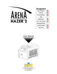
HDTV ENCODER
DM-JV600U
INSTRUCTIONS
POWER
ON
OFF
For Customer Use:
Enter below the Serial No. which is
located on the rear of cabinet. Retain
this information for future reference.
Thank you for purchasing this JVC product.
Before operating this unit, please read the instructions
carefully to ensure the best possible performance.
This instruction book is made from 100% recycle paper.
Model No.
DM-JV600U
Serial No.
LST0159-001C
IMPORTANT SAFEGUARDS
1. Read all of these instructions.
2. Save these instructions for later use.
3. All warnings on the product and in the operating instructions should be adhered to.
4. Unplug this appliance system from the wall outlet before cleaning. Do not use liquid cleaners or aerosol
cleaners. Use a damp cloth for cleaning.
5. Do not use attachments not recommended by the appliance manufacturer as they may cause hazards.
6. Do not use this appliance near water – for example, near a bathtub, washbowl, kitchen sink, or laundry tub,
in a wet basement, or near a swimming pool, etc.
7. Do not place this appliance on an unstable cart, stand, or table. The appliance may fall,
causing serious injury to a child or adult, and serious damage to the appliance.
Use only with a cart or stand recommended by the manufacturer, or sold with the
appliance.
Wall or shelf mounting should follow the manufacturer’s instructions, and should use a
mounting kit approved by the manufacturer.
An appliance and cart combination should be moved with care. Quick stops, excessive
S3125A
force, and uneven surfaces may cause the appliance and cart combination to overturn.
8. Slots and openings in the cabinet and the back or bottom are provided for ventilation, and to insure reliable
operation of the appliance and to protect it from overheating, these openings must not be blocked or
covered. The openings should never be blocked by placing the appliance on a bed, sofa, rug, or other
similar surface. This appliance should never be placed near or over a radiator or heat register. This appliance
should not be placed in a built-in installation such as a bookcase unless proper ventilation is provided.
9. This appliance should be operated only from the type of power source indicated on the marking label. If you
are not sure of the type of power supplied to your home, consult your dealer or local power company. For
appliance designed to operate from battery power, refer to the operating instructions.
10. This appliance system is equipped with a 3-wire grounding type plug (a plug having a third (grounding) pin).
This plug will only fit into a grounding-type power outlet. This is a safety feature. If you are unable to insert
the plug into the outlet, contact your electrician to replace your obsolete outlet. Do not defeat the safety
purpose of the grounding plug.
11. For added protection for this product during a lightning storm, or when it is left unattended and unused for
long periods of time, unplug it from the wall outlet and disconnect the antenna or cable system. This will
prevent damage to the product due to lightning and power-line surges.
12. Do not allow anything to rest on the power cord. Do not locate this appliance where the cord will be abused
by persons walking on it.
13. Follow all warnings and instructions marked on the appliance.
14. Do not overload wall outlets and extension cords as this can result in fire or electric shock.
15. Never push objects of any kind into this appliance through cabinet slots as they may touch dangerous
voltage points or short out parts that could result in a fire or electric shock. Never spill liquid of any kind on
the appliance.
16. Do not attempt to service this appliance yourself as opening or removing covers may expose you to dangerous
voltage or other hazards. Refer all servicing to qualified service personnel.
17. Unplug this appliance from the wall outlet and refer servicing to qualified service personnel under the
following conditions:
a. When the power cord or plug is damaged or frayed.
b. If liquid has been spilled into the appliance.
c. If the appliance has been exposed to rain or water.
d. If the appliance does not operate normally by following the operating instructions. Adjust only those
controls that are covered by the operating instructions as improper adjustment of other controls may result
in damage and will often require extensive work by a qualified technician to restore the appliance to normal
operation.
e. If the appliance has been dropped or the cabinet has been damaged.
f. When the appliance exhibits a distinct change in performance – this indicates a need for service.
18. When replacement parts are required, be sure the service technician has used replacement parts specified
by the manufacturer that have the same characteristics as the original part. Unauthorized substitutions may
result in fire, electric shock, or other hazards.
19. Upon completion of any service or repairs to this appliance, ask the service technician to perform routine
safety checks to determine that the appliance is in safe operating condition.
2
SAFETY PRECAUTIONS
CAUTION
ATTENTION
RISK OF ELECTRIC SHOCK
DO NOT OPEN
RISQUE D’ELECTROCUTION
NE PAS OUVRIR
CAUTION: TO REDUCE THE RISK OF ELECTRIC SHOCK,
DO NOT REMOVE COVER (OR BACK).
NO USER-SERVICEABLE PARTS INSIDE.
REFER SERVICING TO QUALIFIED SERVICE PERSONNEL
ATTENTION: POUR EVITER TOUT RISQUE D’ELECTROCUTION
NE PAS OUVRIR LE BOITER.
AUCUNE PIECE INTERIEURE N’EST
A REGLER PAR L’UTILISATEUR.
SE REFERER A UN AGENT QUALIFIE EN CAS DE PROBLEME.
Le symbole de l’éclair à l’intérieur d’un triangle équilatéral est
destiné à alerter l’utilisateur sur la présence d’une “tension
dangereuse” non isolée dans le boîtier du produit. Cette
tension est suffisante pour provoquer l’électrocution de
personnes.
The lightning flash with arrowhead symbol, within an
equilateral triangle, is intended to alert the user to the
presence of uninsulated “dangerous voltage” within the
product’s enclosure that may be of sufficient magnitude
to constitute a risk of electric shock to persons.
Le point d’exclamation à l’intérieur d’un triangle équilatéral
est destiné à alerter l’utilisateur sur la présence d’opérations
d’entretien importantes au sujet desquelles des
renseignements se trouvent dans le manuel d’instructions.
The exclamation point within an equilateral triangle is
intended to alert the user to the presence of important
operating and maintenance (servicing) instructions in
the literature accompanying the appliance.
*Ces symboles ne sont utilisés qu’aux Etats-Unis.
WARNING:
TO REDUCE THE RISK OF FIRE OR
ELECTRIC SHOCK, DO NOT EXPOSE THIS
APPLIANCE TO RAIN OR MOISTURE.
This unit should be used with 120 V AC only.
CAUTION:
To prevent electric shocks and fire hazards, DO
NOT use any other power source.
NOTE:
The rating plate (serial number plate) is on the rear of the unit.
AVERTISSEMENT:
POUR EVITER LES RISQUES D’INCENDIE OU
D’ELECTROCUTION, NE PAS EXPOSER
L’APPAREIL A L’HUMIDITE OU A LA PLUIE.
Ce magnétoscope ne doit être utilisé que sur
du courant alternatif en 120 V.
ATTENTION:
Afin d’éviter tout resque d’incendie ou
d’électrocution, ne pas utiliser d’autres
sources d’alimentation électrique.
INFORMATION for USA
This equipment has been tested and found to comply with
the limits for a Class A digital device, pursuant to Part 15
of the FCC Rules. These limits are designed to provide
reasonable protection against harmful interference when
the equipment is operated in a commercial environment.
This equipment generates, uses, and can radiate radio
frequency energy and, if not installed and used in
accordance with the instruction manual, may cause
harmful interference to radio communications. Operation
of this equipment in a residential area is likely to cause
harmful interference in which case the user will be
required to correct the interference at his own expense.
REMARQUE:
La plaque d’identification (numéro de série) se trouve
sur le panneau arrière de l’appareil.
WARNING:
The battery used in the DM-JV600U must be replaced
by a JVC authorized service dealer only.
CAUTION
CAUTION
CHANGES OR MODIFICATIONS NOT APPROVED BY
JVC COULD VOID USER’S AUTHORITY TO
OPERATE THE EQUIPMENT.
Use of controls or adjustments or performance of procedures other than those specified herein may result in hazardous radiation exposure.
THIS DEVICE COMPLIES WITH PART 15 OF THE
FCC RULES. OPERATION IS SUBJECT TO THE
FOLLOWING TWO CONDITIONS: (1) THIS DEVICE
MAY NOT CAUSE HARMFUL INTERFERENCE, AND
(2) THIS DEVICE MUST ACCEPT ANY INTERFERENCE RECEIVED, INCLUDING INTERFERENCE
THAT MAY CAUSE UNDESIRED OPERATION.
Note
Place a cover on the terminal not in use.
Static may cause a malfunction or failure of the unit.
INFORMATION for Canada
This Class A digital apparatus meets all requirements of
the Canadian Interference-Causing Equipment Regulations.
Cet appareil numérique de la classe A respecte toutes les
exigences du Reglement sur le matériel brouilleur de
Canada.
3
Main Features
Encoded to MPEG-2(ISO/IEC13818-2)
Thank you for purchasing this
HDTV ENCODER DM-JV600U.
Input SMPTE292M(1080i/720p) standard HDTV digital serial video signal, encode it to MPEG-2(ISO/IEC13818-2)
and output as DVB-ASI TS(Transport Stream).
Supports SDI embedded Audio signal 2 channels
Encodes SMPTE299M standard SDI embedded Audio signal 2 channels to MPEG-1Layer 2 (ISO/IEC11172-3) and
output as TS format.
Dolby™ Digital (AC-3) pass through Compliance
When Dolby™ Digital bitstream is applied to [AES/EBU] terminal, TS Format output could be obtained as this equipment is Dolby™ Digital (AC-3) 1-5.1 channel pass through
compliant.
In addition, when PCM signal is applied to [AES/EBU] terminal, it is possible to encode with MPEG-1 Layer 2.
Equipped with RS-232C terminal
Each feature can be set or operated on the front panel with
FL display. Besides, this unit can be remote-controlled
through the 9-pin connector on the rear panel.
If should be noted that it may be unlawful to re-record
pre-recorded tapes, records, or discs without the consent of the owner of copyright in the sound or video recording, broadcast or cable program and in any literary,
dramatic musical, or artistic work embodied therein.
1U EIA size can be mounted to the rack
Owing to the compact size design, it can be mounted to the
EIA rack.
3-2 Pull down feature
Prior to important video/ audio recording, always perform
a test recording to confirm that video/ audio is properly
recorded.
Please note that we will not provide compensation for
contents of video/ audio recording due to improper video/
audio recording caused by defects when using this equipment.
Dolby is a trademark of Dolby Laboratories.
4
By converting to the SMPTE292M (1080i/720p) standard
HDTV digital serial video signal, input movie film image that
is 24 frame per one second can also be compressed to
high quality using 3-2 Pull down feature.
Equipped with ASI output terminal
Video recording is possible by connecting to D-VHS digital
video recorder from JVC that is equipped with ASI input terminal.
Table of Contents
Main Features ...................................... 4
Table of Contents ................................. 5
Precautions .......................................... 6
Names and Functions
Front Panel ........................................... 7
Rear Panel ........................................... 8
Preparation
Connecting ........................................... 9
Mounting to a Rack ............................ 10
Menu setting
Menu Flow Chart ................................ 11
Menu Setting ...................................... 12
Basic operation
Others
How to Change Menu Setting ............
Restoring the Default Menu
Setting Value ......................................
Starting the Encoding .........................
Checking Operation Status ................
Checking Error Log ............................
Using the Administration Menu ............
INTRODUCTION
Introduction
16
17
18
20
21
22
Error Log ............................................ 24
Setting the 3-2 Pulldown .................... 26
Specifications ..................................... 27
5
Precautions
Maintenance and operating environment
Transportation
Do not store or use this equipment in the following environments. This will cause malfunctioning and damage.
Turn off the power and unplug the power cord from AC
outlet before transportation.
This may cause damage to power cord, fire or electrical
shock.
When moving or carrying the main unit, do no hold it
by the front panel as this can easily be detached by
pulling it toward you.
If moving or carrying the main unit while holding it by the
front panel, the main unit might be caused to fall as a
result of the front panel becoming detached. Such an incident may cause unexpected injury or a malfunction of
the main unit.
• Locations beyond the allowable operating temperature
range of 5 °C and 40 °C.
• Locations beyond the allowable operating humidity
level of 30 % and 80 %.
• Near equipment that produces strong magnetic fields, such
as transformers or motors.
• Near equipment that emits radio waves, such as transceivers and mobile phones.
• Locations with excessive dust and sand.
• Locations that are subject to excessive vibration.
• Locations prone to condensation.
• Locations that emit radiation, X-rays or corrosive gases.
Handling
Do not stack up the equipment to prevent temperature
within from rising.
Do not stand this equipment vertically during use.
Handle this equipment with care. Do not subject it to
physical shock.
Do not place heavy objects or ride on this equipment.
Placing heavy object such as TV monitor or placing bigger object than this unit may cause injury as the object
may become unbalanced and fall.
In addition, the cover may deform due to the weight and
the component inside may damage resulting in fire and
electrical shock.
Wipe this equipment using soft rags.
Wiping with thinner or benzene may dissolve or tarnish
its surface. For dirt that cannot be easily removed, wipe
using a neutral detergent diluted with water, followed by
wiping with a dry cloth.
Do not place object filled with water (vase, flowerpot,
cup, cosmetics and medicine etc).
It will result in fire and electrical shock if water is spilt into
the equipment.
Do not insert anything into the equipment. It will result in
fire and electrical shock if metal or inflammable object is
inserted from the ventilation hole.
Saving Energy
Turn off the power to save energy when the equipment is
not to be used for extensive periods of time.
Fan Replacement
Fans mounted on the inner side of front panel and rear
panel are subject to wear and tear. Replace them every 3
years. It is recommended to fill in the provided label with
replacement date and paste it on this unit.
Consult your local JVC dealer when replacing fan.
Power Cord
Do not use the power cord supplied with this equipment
on other devices.
Do not place heavy object on the power cord nor
placing the power cord under this unit.
This may cause damage to power cord, fire or electrical
shock.
Use the power cord supplied to this unit.
Using the power cord with different voltage rating or damaged power cord may cause fire or electrical shock.
Precautions on operation
The display of this unit may appear 2 seconds after turning on the power. This is compliant to the regulation of
high frequency of power supply and is not faulty.
6
Front Panel
6
5
4
1
POWER
POWER
MULTI FORMAT
HIGH DEFINITION
TELEVISION
ENCODER
ENTER
Switch to turn on/off power. After this is switched
to ON, a “Now Initializing” will be displayed on the
Display 5 of front panel before normal screen is
displayed.
ON
OFF
7
1 [POWER] Power switch
ESC
3 2
About Display
Names and Functions
FAULT
Normal display
HDTV ENCODER
DM-JV600U
After turning on the power, it may take 2 secMemo
onds before display light up.
Press the 8 / 9 buttons
2 [ESC] button
Press this button when switching Display 5 on
the front panel from menu setting display to normal display.
Changing of the setting value in Menu item can
also be cancelled by this button.
Display the control setting status of this unit
Local Running
S Y N : H D - I N S TA R T: A u t o
Display the setting status of how encoding
will start
3 [ENTER] button
Press this button when switching Display 5 on
the front panel from normal display to menu setting display.
Changing of the setting value in Menu item can
also be confirmed by this button.
Memo
Refer to page 16 for changing the menu.
Display the setting status of reference synchronized signal
Press the 8 / 9 buttons
V: 1 0 8 0 i
20000kbps
A:MPEG
384kbps
Display the setting status of encoding of
video signal
Display the setting status of encoding of audio signal
4 [8 / 9 / ; / :] buttons
Press this button to select menu item or change
the setting value of menu item during menu setting display.
Displays the current
operation status
Main Menu
Main Menu
+Configuration Menu
5
Display
The operation status, error content and menu
item of this unit will be displayed.
☞ Following item “About display”
6 [POWER] indicator
Indicate that sub menu is
present
Sub Menu
Configuration Menu
>Save & Reboot
Indicate executable
menu items or alterable
menu setting value
Light up in green during operation.
7 [FAULT] indicator
Light up in orange when error occurs on this unit.
Status Menu
-Status
:Running
Indicate that sub menu is
not present
7
Rear Panel
8
9 0
AC 120V ~ 50 Hz/60 Hz
IN
HDSDI
MONI
OUT
!
2
RS-232C
Input terminal for digital audio signal (PCM or
Dolby™ Digital bitstream). Connect to the digital audio signal output terminal of the device outputting
audio signal.
Input terminal for HD serial digital video signal.
This terminal also receives audio signal when
audio signal is embedded into HD serial digital
video signal.
Connect to the HD serial digital video signal output terminal of the device outputting video signal.
Memo When using the audio signal input terminal,
set the audio input item in the Configuration
Menu to “AES/EBU”.
Page 13 “Configuration Menu”
☞
0 [HD-SDI MONI OUT] Video signal output
Cautions • For the audio signal to be input to AES/EBU
IN terminal, use the 48 kHz audio signal that
is synchronized with video signal.
Memo nal that has not gone through re-clock process
• If Dolby™ Digital bitstream is inputted when
the Audio Format under the Initial Param
Menu is set as “MPEG”, loud sound might
be produced. Make sure that “DD-PT” is set
before inputting Dolby™ Digital bitstream.
cannot be used as a formal SMPTE292M
(1080i/720p) standard HDTV serial digital
video signal.
$ [RS-232C]Remote terminal (D-sub 9pin)
The output signal of HD-SDI MONI.OUT termi-
By connecting to the device for remote control, control of this unit can be performed externally.
! [ASI OUT] TS output terminal (BNC ×2)
TS output terminal.Encodes and outputs the
video signal inputted into HD-SDI IN video signal
input terminal 9 and the audio signal inputted
into AES/EBU IN terminal #.
This terminal also outputs encoded audio signal
when audio signal is embedded into HD serial
digital video signal.
Pin assignment of RS-232C remote terminal
Pin No.
9
Signal name
Content
1
N.C
2
RxD
Received data
3
TxD
Transmitted data
4
N.C
synchronized signal input terminal (BNC)
5
SG
Input external reference synchronized signal.
For reference synchronized signal, use the signal
that is compliant to SMPTE259M (D1).
6
N.C
7
N.C
8
N.C
9
N.C
5
1
6
@ [REF IN (D1)] External reference
When using the external reference synchronized
Memo signal input terminal, set the Sync Mode item in
the Configuration Menu to “REF”.
Page 13 “Configuration Menu”
☞
• When using the external reference synchronized
Cautions signal, keep the phase difference of external reference synchronized signal and input video signal within ±5H (1H: D1signal cycle).
(Phase zero is defined when the forth pin of D1 signal matches with first pin of input video signal.)
• Input D1 signal before turning on the power of this
unit. The encoding may not start if D1 signal is not
input when the power of this unit is turned on.
8
AES/EBU IN
(BNC)
9 [HD-SDI IN] Video signal input terminal (BNC)
Output terminal for through HDTV serial digital
video signal.
For checking the video signal inputted into HDSDI IN video signal input terminal 9 on the rear
panel.
REF IN(D1)
$
# [AES/EBU IN] Audio signal input terminal
Use the power cord supplied to connect to an AC
120 V 50 Hz/60 Hz outlet.
terminal (BNC)
#
1
ASI OUT
8 [AC IN] Power input terminal
@
Tranfer speed
Data bit
Parity
StopBit
Flow Control
Ground
38.4 kbps
8 bit
None
1 bit
None
Connecting
One example of the basic systems using this unit is described below.
Turn OFF the power of all devices before connecting or disconnecting.
HDTV VTR
AUDIO
INPUT
AUDIO INPUT / AUDIO MONITOR SELECT
VIDEO
INPUT
CH1
CH2
CH3
CH4
AES/EBU CH1
L
ANALOG CH1
R
CH2
CH3
CH4
LINE
CH2
CH3
CH4
CPN
SDI
AUDIO
MONITOR
CH1
R
P
dB OVER dB
0
CH3
CH2
R
P
dB OVER dB
0
POWER
SIF
CH4/TRACKING
R
P
dB OVER dB
0
R
P
dB OVER dB
0
+4
+4
+4
+4
+2
+2
+2
+2
0
0
0
0
CFGEN16:9 AP
CTLTCUB DFSERVO
AUTOOFFP.READV.VARPB/EEREMOTE
525
625
CONDITION
COUNTER
RESET
VCON
MENU
SET
HOLD
SEARCH VAR
REMOTE
ON
I
OFF
O
UB
PB
PB/EE
P.PLAY
STILL
M
H
ASSEM VIDEO
S
DA2
DA1
DA3
F
DA4
REC
EJECT
PLAY
PAUSE/STILL
X1
X-1
PHONES
CH2
CH1
REC
CH3
CH4
TRACKING
IN
PULL FOR VARIABLE
METER MODE
FINE
PULL
RELEASE
ENTRY
INSERT
OUT
CANCELPREVIEW
TRACKING
SHIFT
PLAY
Synchronized Signal
Generator
REF signal
PLAYER RECORDER
AUTO EDIT
REVIEW
TC
PREROLL
USER
TOP
VIDEO
AUDIO
STAND BY
REW
STOP
FF
SERVO/SYS
TIME CODE
ON SCREEN
OTHERS
D1 signal
PULL
RELEASE
FWD
REV
HD-SDI OUT
AES/EBU OUT
Dolby™ Digital
ENCODER
DIGITAL AUDIO signal
HD-SDI signal
Dolby™ Digital bitstream
HD-SDI IN
AC IN 120V ~ 50 Hz/60 Hz
REF IN(D1)
MONI.
OUT
IN
HDSDI
2
AES/EBU IN
RS-232C
1
ASI OUT
REF IN(D1)
AES/EBU IN
Preparation
DM-JV600U
ASI OUT
ASI OUT
Supplied power cord
DVB-ASI signal
AC 120V 50 Hz/60 Hz
DVB-ASI signal
DIGITAL VIDEO RECORDER
SR-VDA300U
HDTV DECODER
DM-D4600U
ASI IN
Y
TRISYNC IN
AC IN
DVB-ASI IN
CABLE BOX
Pr
POWER
1
AES/EBU OUT CH1
2
PR/CR
R AUDIO L
HD
ASI
OUT
ALARM
SDI OUT
Pb
RS-422
RS-232C
10BASE-T
Y
AUDIO VIDEO OUT
1
B.B IN
2
IN
VIDEO
REMOTE PAUSE/
AV COMPULINK
OUT
IN
3
AES/EBU OUT CH2
VHF/UHF
ANTENNA
IN(L-1)
R AUDIO
VIDEO
3
AC120V
SD
1A
S VIDEO
OUT
TV
IN(L-2)
S VIDEO
OUT
IN
G
DVB-ASI
IN
SYNC
POL
+
ANALOG VIDEO OUT
(Y, Pb, Pr)
AES/EBU OUT
DIGITAL AUDIO signal
Speaker
AMP
DIGITAL
AUDIO IN
Monitor
ANALOG VIDEO signal
VIDEO IN
If there is interruption of input signal due to switching of HD-SDI input signal or reconnection of signal cable,
Cautions video or audio signal may not output for about 20 seconds.
☞
When [AES/EBU] terminal is set and used as Audio Input (
Page 13) terminal under the Initial Param Menu
screen, noise may be introduced into the audio signals if [REF IN] and [HD-SDI IN] are stopped halfway.
In addition, when the Dolby™ Digital bitstream is inputted from devices such as DVD player that is not synchronized externally, audio signal might be mixed with noise.
Use the following specified cables to avoid misoperation.
• HD-SDI input cable
: 5C-FB, less than 10 m
• HD-SDI monitor output cable : 5C-FB, less than 3 m
This unit may output a full-screen grey signal depends on the following input signal status.
• When the input video signal that is not compliant to SMPTE292M (1080i/720p) is detected
• If the phase difference against input video signal exceeds the range of ±5H when synchronizing to external
signal generator
9
Mounting to a Rack
By making use of the hole on inner side of front panel, this unit can be mounted to EIA rack.
Caution
• When mounting this unit to
rack, mount the L shape
bracket to both ends of the
rack to ensure strength.
• When mounting to the rack,
mount it in the way such that
this unit will not protrude out
from the rack.
(The depth of the rack should
be at least 700 mm)
Remove the foot
Foot
POW
ER
ON
OFF
Remove the front panel
EIA Rack
Mount this unit to rack using the supplied
4 screws
Return the front panel to its original status
POW
ER
ON
OFF
Front Panel
Caution
Do not remove the mounting bracket.The
mounting may become unstable due to
loosen screws. In addition, if the mounting
direction of the bracket is wrong, it will be
extremely dangerous as the bracket will not
be properly mounted onto the rack.
10
Menu Flow Chart
The menu of this unit consists of 3 level of menus namely “Main menu”, “Sub menu” and “Setting items”.
Display screen
Menu Item
Main Menu
Sub Menu
Setting
HDTV ENCODER
DM-JV600U
ENTER
ENTER
ESC
Configuration Menu
+ Operate Param Menu
“Operate Param Menu”
Configuration Menu
+ Initial Param Menu
☞ Page 13
“Initial Param Menu”
Current operation status and error log can
be confirmed.
ENTER
ESC
Configuration Menu
>Save & Reboot
☞ Page 16
“How to Change Menu Setting”
Main Menu
+ Administration Menu
Configuration Menu
>Default & Reboot
☞ Page 17
“Restoring the Default Menu Setting Value”
Administrator menu. Password is required
to operate.
☞ Page 22 “Using the Administration
Menu”
ESC
☞ Page 12
Setting of the encoding bit rate/starting
method of encoding/various parameters,
saving and reset of the menu item setting
are possible.
Main Menu
+ Status Menu
ENTER
ENTER
ESC
• Control Mode
• Start Mode
• Sync Mode
• TS Rate
• Video Mode
• Audio Format
• Audio Input
• Audio ExDelay
• Audio Enable
• PSI Enable
• PAT TS ID
• PMT PID
• PCR PID
• Video PID
• Audio PID
• Video Stream ID
• Audio Stream ID
• Video Copyright
• Video Org/Copy
• Audio Copyright
• Audio Org/Copy
Menu setting
Main Menu
+ Configuration Menu
• Video Rate
• Asp
• 32Pulldown
• Audio Mode
• Audio Rate
• Start
• Stop
Status Menu
- Status : Running
☞ Page 20
“Checking Operation Status”
Status Menu
+ Log
☞ Page 21
“Checking Error Log”
11
Menu Setting
Configuration Menu
: Default setting
Item
Operate Param
Menu
Video Rate
Content
Memo
9000kbps
to
20000kbps to
40000kbps
Set the bit rate of the encoded video signal.
The setting value can be set in 10 kbps step.
Asp
When the Video Mode
item in the menu is set
to “1080i”
16:9 1920 × 1080 16:9 1440 × 1080
16:9 1280 × 1080
When the Video Mode
item in the menu is set
to “720p”
16:9 1280 × 720
Set the horizontal size of the encoded video signal.
16:9 1920 × 1080: Encode with 1920(H) × 1080(V) size
16:9 1440 × 1080: Encode with 1440(H) × 1080(V) size
16:9 1280 × 1080: Encode with 1280(H) × 1080(V) size
16:9 1280 × 720: Encode with 1280(H) × 720(V) size
3-2Pulldown
Auto OFF
Set the 3-2 Pulldown.
Auto : Perform 3-2 Pulldown process automatically
depends on the video signal.
OFF : Does not perform 3-2 Pulldown process.
☞ Page 26 “Setting the 3-2 Pulldown”
Audio Mode
Stereo Single
Set the channel mode of the audio encoded signal.
Stereo : Encode with stereo mode.
Single : Encode with single channel mode (monaural).
Audio Rate
When the Audio Mode
item in the menu is set
to “Stereo”
384kbps 256kbps
192kbps
When the Audio Mode
item in the menu is set
to “Single”
192kbps
128kbps
96kbps
Set the bit rate of the encoded audio signal.
Start
Stop
12
Setting value
Start the encoding.
☞ Page 18 “Starting the Encoding”
Stop the encoding.
☞ Page 19 “Stop the encoding manually”
When the Audio Enable under the Initial Param Menu
screen is set to ON, the upper limit value of Video
Rate is
When the Audio Format under the Initial Param Menu
screen is set as
• MPEG: TS Rate - 700kbps
• DD-PT (Dolby™ Digital
Pass Through) : TS Rate 1000kbps
When Audio Enable is set to
OFF,
• TS Rate - 200kbps
Memo
• The setting value of the
Audio Rate item in the
Operate Param Menu
may change if Audio
Mode setting is changed.
• The setting of Audio
Mode and Audio Rate under the Operate Param
Menu are disallowed
when Audio Format under
the Initial Param Menu is
set as DD-PT (Dolby™
Digital Pass Through).
Configuration Menu
: Default setting
Item
Initial Param
Menu
Control Mode
Start Mode
Setting value
Content
Local Remote
Set the operation mode of this unit.
Local : Set to this mode when operating this unit
using the buttons on the front panel.
Remote : Set to this mode when using RS-232C
terminal $ on the rear panel to perform
remote control of this unit.
Auto Manual
Set the starting mode of encoding.
Auto
: Start the encoding automatically.
Manual : Start the encoding using the menu.
☞ Page 18 “Starting the Encoding”
Memo
HD-IN REF
Set the synchronized signal that is the reference for encoding.
HD-IN : Synchronize with the input video signal.
REF : Synchronize with the D1 signal input into
REF IN terminal @ on the rear panel.
TS Rate
10000kbps
to
21000kbps to
50000kbps
Set the TS bit rate.
The setting value can be changed in 10 kbps step.
Video Mode
1080i 720p
Set the Video Mode.
Encode with 1080i: 1080i format.
Encode with 720p: 720p format.
Audio Format
MPEG DD-PT
(Dolby™ Digital Pass
Through)
Setting the Audio Format.
MPEG : Encoding with MPEG Layer 2.
DD-PT(Dolby™ Digital Pass Through) :
Dolby™ Digital bitstream will be output in TS
Format.
Audio Input
AES/EBU EMB
Select the input audio signal.
AES/EBU : Encode the audio signal input into AES/EBU
terminal # on the rear panel.
EMB
: Encode the Embedded audio signal
input into HD-SDI IN terminal 9 on the
rear panel.
Audio ExDelay
1ms
to
10ms to
500ms
This setting is meant for compensating the delays
introduced when encoders are connected to
external equipment.
(Denary, Millisecond unit)
Setting value is 1 ms step variable.
ON OFF
Set whether to output audio signal or not.
ON : Output audio information.
OFF : Does not output audio information.
When input video signal is used in synchronized mode, video signal may not output for
about 20 seconds due
to switching of signal or
reconnection of signal
cable.
Menu setting
Sync Mode
Memo
The setting value of the
Video Rate item in the Operate Param Menu may
change if TS Rate setting
value is changed.
Memo
The setting value of the Asp
item in the Operate Param
Menu may change if Video
Mode setting value is
changed.
Memo
Audio Enable
This setting is only valid
when Audio Format is set
as DD-PT (Dolby™ Digital
Pass Through).
13
Menu Setting
Configuration Menu (continued)
: Default setting
Item
Setting value
Content
ON
OFF
Set the PSI (Program Specific Information) to ON/
OFF.
ON : PAT and PMT will be output.
OFF : PAT and PMT will not be output.
PAT TS ID
0001
to
0001
to
FFFF
Set the ID of PAT TS.
PAT TS ID is the Transport Stream ID within PAT.
PAT (Program Association Table) is the correspondences
table of Program number and PMT PID.
PMT PID
0010
to
0010
to
1FFE
Set the PMT Packet ID.
PMT (Program Map Table) is an index table that
designates the various stream PIDs which
constituted the program.
PCR PID
0010
to
0101
to
1FFE
Set the PCR Packet ID.
PCR (Program Clock Reference) is clock data that is
output periodically.
It is used by the decoder to synchronize with internal
clock for PLL synchronization.
Video PID
0020
to
0102
to
1FFE
Set the Video Packet ID.
Audio PID
0020
to
0103
to
1FFE
Set the Audio Packet ID.
Video Stream ID
E0
to
E0
to
EF
Set the ID of Video PES stream.
Initial Param
Menu
PSI Enable
14
Configuration Menu (continued)
: Default setting
Initial Param
Menu
Audio Stream ID
Setting value
Content
Memo
C0
to
C0
to
DF
Set the ID of Audio PES stream.
Video Copyright
OFF
ON
Set the copyright flag of Video PES.
OFF : Set the copyright flag of Video PES to OFF.
ON : Set the copyright flag of Video PES to ON.
Video Org/Copy
Org
Copy
Set the Original/ Copy of Video PES.
Org : Set the Video PES to Original.
Copy : Set the Video PES to Copy.
Audio Copyright
OFF
ON
Set the copyright flag of Audio PES.
OFF : Set the copyright flag of Audio PES to OFF.
ON : Set the copyright flag of Audio PES to ON.
Audio Org/Copy
Org
Copy
Set the Original/ Copy of Audio PES.
Org : Set the Audio PES to Original.
Copy : Set the Audio PES to Copy.
Save & Reboot
Save the setting value of the menu and restart this unit.
☞ Page 18 “Starting the Encoding”
Default & Reboot
Return the setting value of the menu to default and
restart this unit.
☞ Page 17 “Restoring the Default Menu Setting Value”
This setting is disabled
when Audio Format under
the Initial Param Menu
screen is set as DD-PT
(Dolby™ Digital Pass Through).
(Fixed as 0xBD)
Menu setting
Item
15
How to Change Menu Setting
The various features of this unit can be set using the menu. The setting value, which is stored in the
internal memory will reappear upon turning on the power.
Example
Remote control of this unit
can be achieved by using
the RS-232C terminal on
the rear panel.
[Configuration Menu]
≠
[Initial Param Menu]
≠
[Control Mode]
≠
“Remote”
8 / 9 / ; / :buttons
Display
POWER
POWER
FAULT
MULTI FORMAT
HIGH DEFINITION
TELEVISION
ENCODER
ENTER
ESC
ON
OFF
ENTER ESC
button button
Operation Flow Chart
Display Flow Chart
Press the ENTER button
Main Menu
Main Menu screen will be displayed.
+Configuration Menu
Press the 8 / 9 buttons
Main Menu
Select the Configuration Menu.
+Configuration Menu
Press the ENTER button
Configuration Menu
Configuration Menu screen will be displayed.
+Operate Param Menu
Press the 8 / 9 buttons
Configuration Menu
Select the Initial Param Menu.
+Initial Param Menu
Press the ENTER button
Initial Param Menu
Initial Param Menu screen will be displayed.
> C o n t ro l M o d e : L o c a l
Press the 8 / 9 buttons
Initial Param Menu
Select the Control Mode item and press the ENTER button.
> C o n t ro l M o d e : L o c a l
Press the 8 / 9 buttons
Initial Param Menu
Select the “Remote” and press the ENTER button.
>Control Mode:Remote
Memo
Press the ESC button
Initial Param Menu
>Save & Reboot ?
Press the ENTER button
The Operate Param Menu
setting will be reflected in
the output even if “Save &
Reboot” is not executed.
Caution
..Now Initializing..
HDTV ENCODER
DM-JV600U
16
Do not turn off the power
switch during “Now Initializing” display.
The setting value may not
be saved or may return to
default setting.
Restoring the Default Menu Setting Value
Each feature that has been set using the menu can be returned to default (factory setting).
All the menu settings return to default.
Display Flow Chart
Press the ENTER button
Main Menu
Main Menu screen will be displayed.
+Configuration Menu
Press the 8 / 9 buttons
Main Menu
Select the Configuration Menu.
+Configuration Menu
Press the ENTER button
Configuration Menu
Configuration Menu screen will be displayed.
+Operate Param Menu
Press the 8 / 9 buttons
Configuration Menu
Select the Default & Reboot.
>Default & Reboot
Press the ENTER button
Configuration Menu
Execution confirmation screen will be displayed.
>Default & Reboot ?
Basic operation
Operation Flow Chart
Caution
Do not turn off the
power switch during
“Now Initializing” display.
Press the ENTER button
Setting to default of the menu setting and reboot of this
unit will be performed.
..Now Initializing..
HDTV ENCODER
DM-JV600U
17
Starting the Encoding
There are 2 ways to start the encoding. One is to start the encoding automatically and the other one
is to start it manually by setting the menu.
Display
8 / 9 / ; / :buttons
POWER
POWER
FAULT
MULTI FORMAT
HIGH DEFINITION
TELEVISION
ENCODER
ENTER
ESC
ON
OFF
ENTER ESC
button button
Start the encoding automatically
Operation Flow Chart
Press the ENTER button
Display Flow Chart
Initial Param Menu
Display the Initial Param Menu screen according to
steps 1~5 on Page 16 “How to Change Menu Setting”.
>Control Mode :Local
Press the 8 / 9 buttons
Initial Param Menu
Select the Start Mode item and press the ENTER button.
>Start Mode
Memo
The default setting of the
Start Mode item is set to
“Auto” in order to start the
encoding automatically.
Page 13 “Start Mode
item”
☞
:Auto
Memo
Press the 8 / 9 buttons
Initial Param Menu
Select the “Auto” and press the ENTER button.
>Start Mode
Press the ESC button
Initial Param Menu
:Auto
☞
>Save & Reboot ?
Press the ENTER button
The encoding will start after the menu setting is saved
and reboot of this unit is performed.
..Now Initializing..
HDTV ENCODER
DM-JV600U
18
The encoding can be manually started or stopped if
the Start Mode item in the
menu is set to “Manual”.
Page 19 “Start the
encoding manually”
☞
Start the encoding manually
Memo
Operation Flow Chart
Display Flow Chart
Press the ENTER button
Main Menu
Main Menu screen will be displayed.
+Configuration Menu
Press the 8 / 9 buttons
Configuration Menu
Select the Configuration Menu and press the ENTER
button.
Press the 8 / 9 buttons
Select the Operate Param Menu and press the ENTER button.
The encoding will stop if menu
item has been changed during manual encoding and
“>Save&Reboot” has been
excecuted.
Start the encoding manually
once again.
+Operate Param Menu
Operate Param Menu
VideoRate:20000kbps
Press the 8 / 9 buttons
Operate Param Menu
Select the Start item and press the ENTER button.
>Start?
Basic operation
Set the Start Mode item
in the menu to “Manual” according to the procedure on
Page 18 “Start the
encoding automatically”.
Press the ENTER button
This starts the encoding.
Stop the encoding manually
Operation Flow Chart
Display Flow Chart
Press the ENTER button
Main Menu
Main Menu screen will be displayed.
+Configuration Menu
Press the 8 / 9 buttons
Configuration Menu
Select the Configuration Menu and press the ENTER
button.
Press the 8 / 9 buttons
Select the Operate Param Menu and press the ENTER button.
+Operate Param Menu
Operate Param Menu
VideoRate:20000kbps
Press the 8 / 9 buttons
Operate Param Menu
Select the Stop item and press the ENTER button.
>Stop?
Press the ENTER button
Stop the encoding.
19
Checking Operation Status
The operation status of this unit can be confirmed from the display.
Display
8 / 9 / ; / :buttons
POWER
POWER
FAULT
MULTI FORMAT
HIGH DEFINITION
TELEVISION
ENCODER
ENTER
ON
ESC
OFF
ENTER ESC
button button
Operation Flow Chart
Display Flow Chart
Press the ENTER button
Main Menu
Main Menu screen will be displayed.
+Configuration Menu
Press the 8 / 9 buttons
Main Menu
Select the Status Menu.
+Status Menu
Press the ENTER button
Status Menu screen will be displayed.
Press the 8 / 9 buttons
Current operation status will be displayed by selecting
the Status item.
Status Menu
-Status
:Running
Status Menu
-Status
:Running
Memo
Indicate that the encoding
is in process.
Status Menu
-Status
:Running
Indicate that the encoding
is in standby status.
Status Menu
-Status
:Ready
Status Menu
-Status
20
:Fatalerror
Indicates that fatal error
has occurred.
Page 24 “Error Log”
☞
Checking Error Log
The error occurrence can be confirmed on the display. Up to 64 occurrences can be stored.
Display Flow Chart
Press the ENTER button
Main Menu
Main Menu screen will be displayed.
+Configuration Menu
Press the 8 / 9 buttons
Main Menu
Select the Status Menu.
+Status Menu
Press the ENTER button
Status Menu
Status Menu screen will be displayed.
-Status
Press the 8 / 9 buttons
Status Menu
Select the Log item and press the ENTER button.
+Log
Press the 8 / 9 buttons
00:Feb07 14:06 0001
The error log stored will be displayed.
For detailed error log display, read page 24 “Error log”.
-system boot
:Running
Basic operation
Operation Flow Chart
21
Using the Administration Menu
The information regarding built-in program or firmware version can be obtained from the
Administration Menu. In addition, clock setting and the display brightness could be adjusted.
* Please carry out the clock setting before use.
8 / 9 / ; / :buttons
Display
Examples of setting
Setting the clock using
the Administration Menu
screen.
POWER
POWER
FAULT
MULTI FORMAT
HIGH DEFINITION
TELEVISION
ENCODER
ENTER
ON
ESC
OFF
ENTER ESC
button button
Operation Flow Chart
Display Flow Chart
Press the ENTER button
Main Menu
Main Menu screen will be displayed.
+Configuration Menu
Press the 8 / 9 buttons
Main Menu
Select the Administration Menu.
+Administration Menu
Press the ENTER button
Administration Menu
The Administration Menu screen will be displayed.
-Model
:DM-JV600U
Press the 8 / 9 buttons
Choose the Time item and press ENTER button.
Administration Menu
>Time : 04/03/19
Press the 8 / 9/; / : Buttons
; / : Buttons : Move the cursor to
the highlight
the places when changes are to
be made.
8/ 9 Buttons
: Change the values highlighted by
the cursor.
Press the [ENTER] button once charges are made.
22
22:00
Administration Menu
>Time : 04/03/19
22:0
At the selected places,
cursor will start to blink.
Administration menu
Item
Content
Model
Displays the model name.
SerNo
Displays the serial number.
Time
Setting the Clock.
Year/Month/Day Hour : Minute (For the Year setting,
only the last 2 digits of the year will be used)
FL Brghtness
(Initial Setting: 0)
Setting the Display brightness.
Firm
Displays the firmware version.
Ucode
Displays the version of the µ code.
Boot
Displays the version of boot program.
MISC FPGA
Displays the version of MISC FPGA.
STC FPGA
Displays the version of STC FPGA.
I/O PWB
Displays the version of I/O PWB.
I/O VI PLD
Displays the version of I/O VI PLD.
I/O AU PLD
Displays the version of I/O AU PLD.
Basic operation
Setting range is between 0 to 3.
0 : Brightest setting.
23
Error Log
The stored error log can be displayed by performing the operation on page 21 “Checking Error Log”.
The error content is displayed by error code.
Display
a
b
c
d
e
a: Error log No.
b: Error occurrence date
c: Error occurrence time
d: Error code
e: Error content
00 : Feb07 14 : 06 0001
-system boot
* For the error content with plenty of characters, press
the ; / : buttons to scroll the display.
* The date and hour of this unit is adjusted to Greenwich Mean Time (GMT).
Error code
Error code:Error content
Cause of error
0001:
system boot
Restart of this unit has been performed.
0020:
communication error
The communication error caused by control
device communication has occurred.
0021:
command parameter error
The value of command and parameter created
by control device communication is abnormal.
0022:
command busy
This unit has received action command
when it is busy.
0040:
sync input error
The synchronized signal cannot be detected.
Troubleshooting
Confirm the connection to external
device.
Confirm the setting of external device.
Confirm the connection to external
synchronized signal generator and
the synchronized signal itself.
0041:
sync input error recover
0050:
sync no input timeout error
The detection of the synchronized signal
has timed out when this unit restarts.
0080:
enc hardware video input error
The video input signal is abnormal.
Confirm the connection between
HD-SDI IN terminal and connected
device.
Confirm the signal input into HDSDI IN terminal
The audio input signal is abnormal.
Confirm the connection between
AES/EBU IN terminal and connected device.
Confirm the signal input into AES/
EBU IN terminal.
Resync process has occured when synchronizing to video input signal.
Confirm the connection between HDSDI IN terminal and connected
device(Frequent reconnection of the
connector may cause the error).
Confirm the signal input into HD-SDI IN
terminal.
0081:
enc hardware video input error recover
0084:
enc hardware audio input error
0085:
enc hardware audio input error recover
0088:
enc hardware resync
24
Error code
Error code:Error content
Cause of error
Troubleshooting
0002:
parameter error
The content of the internal parameter
(default parameter and others) is abnormal.
0008:
FAN stop error
FAN operation is abnormal.
This unit is abnormal.
Switch the power to “OFF” and turn
on the power again. Consult your
local JVC dealer if the problem is
still unsolved.
0009:
FAN stop error recover
001a:
FAN stop timeout error
0013:
hardware fatal error
The hardware of this unit is abnormal.
0014:
software fatal error
The software of this unit is abnormal.
0015:
system boot fatal error
The restart of this unit is abnormal.
0044:
video frame interrupt timeout error
The interruption of video frame has
timed out.
0045:
video frame interrupt timeout error recover
0060:
domino chip running error
The IC inside this unit is abnormal.
0061:
domino chip running error recover
0072:
domino chip boot fatal error
0073:
domino chip running fatal error
00a0:
enc software video input error
The process of the input stage of video
signal is abnormal.
Others
00a1:
enc software video input error recover
00a2:
enc software video running error
00a3:
enc software video running error recover
00a8:
enc software audio input error
The process of the input stage of audio
signal is abnormal.
00a9:
enc software audio input error recover
00aa:
enc software audio running error
00ab:
enc software audio running error recover
25
Setting the 3-2 Pulldown
Encoding image film material
It is required to convert the video signal (Pulldown) in order to view the image recorded with
24 frames per second such as movie film on a system for HDTV video signal that is 30
frames per second (60 field) used in TV broadcasting. Normally, HDTV VTR utilize 3 - 2
Pulldown (Telecine) method to achieve image signal conversion before recording on tape.
When this equipment is encoding signals which have been recorded with 3 - 2 Pulldown
processing, it is possible to encode by automatically skip 24 frames in order to increase
compression ratio. (Inverse Telecine)
3-2 Pulldown auto setting
For 3-2 Pulldown method, the odd number frame is converted to 2 fields and the even number frame is converted to 3 fields. With this feature, it is possible to convert 2 frames into 5
fields which means that 24 frames could be converted into 60 fields.
Film
1st scene
HDTV VTR Field Field
1
2
Frame 1
ENCODER
Frame 1
2nd scene
3rd scene
Field Field Field Field
1
2
1
2
Frame 2
Frame 3
Frame 2
4th scene
Field Field
1
2
Field Field
1
2
Frame 4
Frame 5
Frame 3
Frame 4
When 3- 2 Pulldown under the Operate Param Menu is set to AUTO, input image signals will
automatically be detected for 3 -2 Pulldown processing information, unnecessary fields will
be discarded and only the original 24 frames will be encoded.
26
Specifications
Video input
HD SDI IN ×1
SMPTE292M (common for 1080i/720p)
SMPTE299M (Embedded Audio)
800 mVp-p, 75 Ω (BNC unbalanced)
1080i:1920 × 1080 frame frequency 29.97Hz
720p:1280 × 720 frame frequency 59.94Hz
Audio input
AES/EBU IN ×1
AES/EBU
(48 kHz sampling frequency synchronized with video
signal)
1 Vp-p, 75 Ω (BNC unbalanced)
Synchronized input
REF IN ×1
<Output signal>
SMPTE259M
800 mVp-p, 75 Ω (BNC unbalanced)
Video output
MONITOR OUT ×1
SMPTE292M(common for 1080i/720p)
800 mVp-p, 75 Ω (BNC unbalanced)
DVB/ASI(188byte format,packet mode)
800 mVp-p, 75 Ω (BNC unbalanced)
ASI OUT ×2
<Video encoding>
MPEG-2
(ISO/IEC13818-2)
Video encoding profile
1080i MP@HL
1920 × 1080 59.94 Hz
1080i MP@HL
1440 × 1080 59.94 Hz
1080i MP@HL
1280 × 1080 59.94 Hz
720p MP@H14L 1280 × 720 59.94 Hz
<Audio encoding>
MPEG-1 Layer 2
(ISO/IEC11172-3)
Stereo mode
Bit rate
Sampling
Video bit rate
9Mbps~40 Mbps
9Mbps~40 Mbps
9Mbps~40 Mbps
9Mbps~40 Mbps
Single mode
Bit rate
384 kbps
256 kbps
192 kbps
48 kHz
192 kbps
128 kbps
96 kbps
48 kHz
Sampling
Dolby™ Digital(AC-3) Pass
Through
Channel : 1-5.1 channel
Sampling : 48 kHz
Bit rate : 56 kbps to 640 kbps
<General>
Interface
Power supply
Power consumption
Allowable operating temperature
Allowable storage temperature
Allowable operating humidity
Mass
RS-232C ×1
AC 120 V 50 Hz/60 Hz
70 W , 0.6 A
5 °C to 40 °C
–20 °C to 60 °C
30 % to 80 %
Approx. 10 k˝
<Accessories>
Instruction Manual .............. ×1
Power cord (2.4 m) ................... ×1
Screws for mounting rack ... ×4
Label ................................... ×1
<Appearance>
465
430
[unit : mm]
REF IN(D1)
ASI OUT
HDSDI
AC 120V ~ 50/60Hz
<Input signal>
IN
MONI
OUT
2
1
AES/EBU IN
RS-232C
635
665
25
5
49
ON
OFF
44
POWER
482
*Dolby is a trademark of Dolby Laboratories.
*Specifications and appearance of this unit are subject to change for improvement without prior notice.
27
DM-JV600U
HDTV ENCODER
VICTOR COMPANY OF JAPAN, LIMITED
¨
¨
is a registered trademark owned by VICTOR COMPANY OF JAPAN, LTD.
is a registered trademark in Japan, the U.S.A., the U.K. and many other countries.
© 2004 VICTOR COMPANY OF JAPAN, LIMITED
Printed in japan
LST0159-001C