1
Programming Manual
Logix5000 Controllers ASCII Strings
Catalog Numbers 1756-L1, 1756-L55, 1756-L61, 1756-L62, 1756-L63, 1769-L31, 1769-L32C, 1769-L32E, 1769-L35CR, 1769-L35E,
1789-L60, 1794-L34, PowerFlex 700S/SE
Important User Information
Solid-state equipment has operational characteristics differing from those of electromechanical equipment. Safety
Guidelines for the Application, Installation and Maintenance of Solid State Controls (publication SGI-1.1 available from
your local Rockwell Automation sales office or online at http://www.rockwellautomation.com/literature/) describes some
important differences between solid-state equipment and hard-wired electromechanical devices. Because of this difference,
and also because of the wide variety of uses for solid-state equipment, all persons responsible for applying this equipment
must satisfy themselves that each intended application of this equipment is acceptable.
In no event will Rockwell Automation, Inc. be responsible or liable for indirect or consequential damages resulting from
the use or application of this equipment.
The examples and diagrams in this manual are included solely for illustrative purposes. Because of the many variables and
requirements associated with any particular installation, Rockwell Automation, Inc. cannot assume responsibility or
liability for actual use based on the examples and diagrams.
No patent liability is assumed by Rockwell Automation, Inc. with respect to use of information, circuits, equipment, or
software described in this manual.
Reproduction of the contents of this manual, in whole or in part, without written permission of Rockwell Automation,
Inc., is prohibited.
Throughout this manual, when necessary, we use notes to make you aware of safety considerations.
WARNING: Identifies information about practices or circumstances that can cause an explosion in a hazardous environment, which may
lead to personal injury or death, property damage, or economic loss.
ATTENTION: Identifies information about practices or circumstances that can lead to personal injury or death, property damage, or
economic loss. Attentions help you identify a hazard, avoid a hazard, and recognize the consequence
SHOCK HAZARD: Labels may be on or inside the equipment, for example, a drive or motor, to alert people that dangerous voltage may be
present.
BURN HAZARD: Labels may be on or inside the equipment, for example, a drive or motor, to alert people that surfaces may reach
dangerous temperatures.
IMPORTANT
Identifies information that is critical for successful application and understanding of the product.
Allen-Bradley, Rockwell Software, Rockwell Automation, and TechConnect are trademarks of Rockwell Automation, Inc.
Trademarks not belonging to Rockwell Automation are property of their respective companies.
Summary of Changes
This manual contains new and updated information.
IMPORTANT RSLogix 5000 programming software is now known as Studio 5000™ Logix Designer application, a
component of Studio 5000 Engineering and Design Environment.
The following controllers are no longer supported in the Logix Designer
application, version 21.
Catalog Number
Description
1756-L61
ControlLogix 5561 Controller
1756-L61S
ControlLogix 5561S Controller
1756-L62
ControlLogix 5562 Controller
1756-L62S
ControlLogix 5562S Controller
1756-L63
ControlLogix 5563 Controller
1756-L63S
ControlLogix 5563S Controller
1756-L64
ControlLogix 5564 Controller
1756-L65
ControlLogix 5565 Controller
1768-L43
CompactLogix 5343 Controller
1768-L43S
CompactLogix 5343S Controller
1768-L45
CompactLogix 5345 Controller
1768-L45S
CompactLogix 5345S Controller
1769-L23E-QBF1
CompactLogix 5323E-QB1 Controller
1769-L23E-QBFC1
CompactLogix 5323E-QBFC1 Controller
1769-L23-QBFC1
CompactLogix 5323-QBFC1 Controller
1769-L31
CompactLogix 5331 Controller
1769-L32C
CompactLogix 5332C Controller
1769-L32E
CompactLogix 5332E Controller
1769-L35CR
CompactLogix 5335CR Controller
1769-L35E
CompactLogix 5335E Controller
Changes throughout this revision are marked by change bars, as shown in the
margin of this page.
There are a number of minor changes throughout this publication that were
made to clarify existing information. The major changes are listed below.
Change
Page
Updated sample project folder location.
page 22
Updated data type editor image.
page 23
Rockwell Automation Publication 1756-PM013C-EN-P - November 2012
3
Summary of Changes
Notes:
4
Rockwell Automation Publication 1756-PM013C-EN-P - November 2012
Table of Contents
Preface
Studio 5000 Engineering and Design Environment and
Logix Designer Application . . . . . . . . . . . . . . . . . . . . . . . . . . . . . . . . . . . . . . . . . 7
In This Manual . . . . . . . . . . . . . . . . . . . . . . . . . . . . . . . . . . . . . . . . . . . . . . . . . . . . 7
Chapter 1
Communicating with an ASCII Device Introduction. . . . . . . . . . . . . . . . . . . . . . . . . . . . . . . . . . . . . . . . . . . . . . . . . . . . . . . 9
Connect the ASCII Device . . . . . . . . . . . . . . . . . . . . . . . . . . . . . . . . . . . . . . .
Configure the Serial Port . . . . . . . . . . . . . . . . . . . . . . . . . . . . . . . . . . . . . . . . .
Configure the User Protocol . . . . . . . . . . . . . . . . . . . . . . . . . . . . . . . . . . . . . .
Create String Data Types . . . . . . . . . . . . . . . . . . . . . . . . . . . . . . . . . . . . . . . . .
Read Characters from the Device . . . . . . . . . . . . . . . . . . . . . . . . . . . . . . . . . .
Send Characters to the Device. . . . . . . . . . . . . . . . . . . . . . . . . . . . . . . . . . . . .
Enter ASCII Characters . . . . . . . . . . . . . . . . . . . . . . . . . . . . . . . . . . . . . . . . . .
10
11
12
14
15
17
19
Chapter 2
Processing ASCII Characters
Introduction. . . . . . . . . . . . . . . . . . . . . . . . . . . . . . . . . . . . . . . . . . . . . . . . . . . . .
Extract a Part of a Bar Code . . . . . . . . . . . . . . . . . . . . . . . . . . . . . . . . . . . . . . .
Look Up a Bar Code. . . . . . . . . . . . . . . . . . . . . . . . . . . . . . . . . . . . . . . . . . . . . .
Create the PRODUCT_INFO Data Type . . . . . . . . . . . . . . . . . . . . .
Search for the Characters. . . . . . . . . . . . . . . . . . . . . . . . . . . . . . . . . . . . . .
Identify the Lane Number. . . . . . . . . . . . . . . . . . . . . . . . . . . . . . . . . . . . .
Reject Bad Characters. . . . . . . . . . . . . . . . . . . . . . . . . . . . . . . . . . . . . . . . .
Enter the Product IDs and Lane Numbers . . . . . . . . . . . . . . . . . . . . . .
Check the Bar Code Characters . . . . . . . . . . . . . . . . . . . . . . . . . . . . . . . . . . .
Convert a Value. . . . . . . . . . . . . . . . . . . . . . . . . . . . . . . . . . . . . . . . . . . . . . . . . .
Decode an ASCII Message . . . . . . . . . . . . . . . . . . . . . . . . . . . . . . . . . . . . . . . .
Build a String . . . . . . . . . . . . . . . . . . . . . . . . . . . . . . . . . . . . . . . . . . . . . . . . . . . .
ASCII Character Codes. . . . . . . . . . . . . . . . . . . . . . . . . . . . . . . . . . . . . . .
Rockwell Automation Publication 1756-PM013C-EN-P - November 2012
21
21
22
23
23
24
24
25
25
26
27
28
29
5
Table of Contents
6
Rockwell Automation Publication 1756-PM013C-EN-P - November 2012
Preface
Studio 5000 Engineering and
Design Environment and
Logix Designer Application
The Studio 5000™ Engineering and Design Environment combines engineering
and design elements into a common environment. The first element in the
Studio 5000 environment is the Logix Designer application. The Logix Designer
application is the rebranding of RSLogix™ 5000 software and will continue to be
the product to program Logix5000™ controllers for discrete, process, batch,
motion, safety, and drive-based solutions.
The Studio 5000 environment is the foundation for the future of
Rockwell Automation® engineering design tools and capabilities. It is the one
place for design engineers to develop all the elements of their control system.
In This Manual
This manual shows how to manipulate ASCII strings in Logix5000 controllers.
This manual is one of a set of related manuals that show common procedures for
programming and operating Logix5000 controllers. For a complete list of
common procedures manuals, see the Logix 5000 Controllers Common Procedures
Programming Manual, publication 1756-PM001.
The term Logix5000 controller refers to any controller that is based on the
Logix5000 operating system, such as:
· CompactLogix controllers
· ControlLogix controllers
· DriveLogix controllers
· FlexLogix controllers
· SoftLogix5800 controllers
Rockwell Automation Publication 1756-PM013C-EN-P - November 2012
7
Preface
Notes:
8
Rockwell Automation Publication 1756-PM013C-EN-P - November 2012
Chapter
1
Communicating with an ASCII Device
Introduction
You can exchange ASCII data with a device through the serial port of the
controller. For example, you can use the serial port to:
· read ASCII characters from a weigh scale module or bar code reader.
· send and receive messages from an ASCII triggered device, such as a
MessageView terminal.
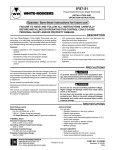
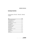
Connection from the serial port of the controller to the ASCII device
42237
In addition to the controller serial port, firmware revision 3.1 and greater of the
1756-EWEB EtherNet/IP Web Server module supports a socket interface that
lets Logix5000 controllers exchange ASCII data using TCP or UDP socket
services. See the EtherNet/IP Web Server User Manual, publication ENETUM0527, revision C or later.
Rockwell Automation Publication 1756-PM013C-EN-P - November 2012
9
Chapter 1
Communicating with an ASCII Device
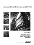
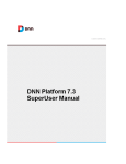
Connect the ASCII Device
1. On the serial port of the ASCII device, determine which pins send signals
and which pins receive signals.
2. Connect sending pins to corresponding receiving pins and attach jumpers.
If the communications
Then wire the connectors
Handshake
ASCII Device
Controller
1 CD
1 CD
2 RDX
2 RDX
3 TXD
3 TXD
4 DTR
4 DTR
COMMON
COMMON
6 DSR
6 DSR
7 RTS
7 RTS
8 CTS
8 CTS
9
9
42231
Do not handshake
ASCII Device
Controller
1 CD
1 CD
2 RDX
2 RDX
3 TXD
3 TXD
4 DTR
4 DTR
COMMON
COMMON
6 DSR
6 DSR
7 RTS
7 RTS
8 CTS
8 CTS
9
9
3. Attach the cable shield to both connectors.
4. Connect the cable to the controller and the ASCII device.
10
Rockwell Automation Publication 1756-PM013C-EN-P - November 2012
42232
Communicating with an ASCII Device
Chapter 1
1. On the Online toolbar in the controller project, click the controller
button.
Configure the Serial Port
2. Select the Serial Port tab.
3. Select User mode and enter the configuration settings for the serial port.
• Select the baud rate, data bits, parity, and stop bits.
• Select the Control Line option:
If
And
And this is the
You are not using a modem
You are using a modem
Select
Then
No Handshaking
Both modems in a point-to-point
link are full-duplex
Full Duplex
Master modem is full-duplex
master controller.
while slave modem is half-duplex
slave controller
Full Duplex
Half Duplex
Check the Continuous Carrier check box.
All modems in the system are
half-duplex
Half Duplex
Clear the Continuous Carrier check box
(default).
• For RTS Send Delay, enter the delay (in 20 ms units) between the time
the RTS signal turns on (high) and the time that data is sent. For
example, a value of 4 produces an 80 ms delay.
• For RTS Off Delay, enter the delay (in 20 ms units) between the time
the last character is sent and the time that the RTS signal turns off
(low).
4. Click Apply.
Rockwell Automation Publication 1756-PM013C-EN-P - November 2012
11
Chapter 1
Communicating with an ASCII Device
Configure the User Protocol
1. Select the User Protocol tab.
42252
• Enter a buffer size that is greater than or equal to the greatest number of
characters in a transmission. (Twice the number of characters is a good
guideline.)
• For ABL or ARL instructions, enter termination characters to mark the
end of the data. For ASCII codes, see the back cover of this manual.
If the device sends
Then
One termination character • In the Termination Character 1 text box, type
the hexadecimal ASCII code for the first
character.
• In the Termination Character 2 text box, type
$FF.
Two termination
characters
Notes
For printable characters,
such as 1 or A, type the
character.
In the Termination Character 1 and 2 text boxes,
type the hexadecimal ASCII code for each character.
• For AWA instruction, enter append characters. For ASCII codes, see
the inside back cover of this manual.
To append
Then
Notes
One character
• In the Append Character 1 text box, type the
hexadecimal ASCII code for the first character.
• In the Append Character 2 text box, type $FF.
For printable characters,
such as 1 or A, type the
character.
Two characters
In the Append Character 1 and 2 text boxes, type
the hexadecimal ASCII code for each character.
• If the ASCII device is configured for XON/XOFF flow control, select
the XON/XOFF check box.
• If the ASCII device is a CRT or is pre-configured for half duplex
transmission, select the Echo Mode check box.
12
Rockwell Automation Publication 1756-PM013C-EN-P - November 2012
Communicating with an ASCII Device
Chapter 1
• Select the Delete Mode:
If the ASCII device is
Select
Notes
CRT
CRT
• The DEL character ($7F) and the character that precedes the DEL character are not sent to
the destination.
• If echo mode is selected and an ASCII instruction reads the DEL character, the echo returns
three characters: BACKSPACE SPACE BACKSPACE ( $08 $20 $08).
Printer
Printer
• The DEL character ($7F) and the character that precedes the DEL character are not sent to
the destination.
• If echo mode is selected and an ASCII instruction reads the DEL character, the echo returns
two characters: / ($2F) followed by the character that was deleted.
None of the above
Ignore
The DEL character ($7F) is treated as any other character.
2. Click OK.
Rockwell Automation Publication 1756-PM013C-EN-P - November 2012
13
Chapter 1
Communicating with an ASCII Device
Store ASCII characters in tags that use a string data type.
Create String Data Types
42811
42812
You can use the default STRING data type. It stores
up to 82 characters.
IMPORTANT
or
You can create a new string data type to store the number of
characters that you define.
Use caution when you create a new string data type. If you later decide to change the size of the
string data type, you may lose data in any tags that currently use that data type.
If you
Make a string data type smaller
Make a string data type larger
Then
·The data is truncated.
·The LEN is unchanged.
The data and LEN is reset to zero.
1. In the controller organizer, right-click Strings and choose New String
Type…
2. Type a name for the data type.
3. Type the maximum number characters that this string data type will store.
4. Click OK.
42233
14
Rockwell Automation Publication 1756-PM013C-EN-P - November 2012
Communicating with an ASCII Device
Read Characters from the Device
Chapter 1
As a general rule, before you read the buffer, use an ACB or ABL instruction to
verify that the buffer contains the required characters.
· An ARD or ARL instruction continues to read the buffer until the
instruction reads the required characters.
· While an ARD or ARL instruction is reading the buffer, no other ASCII
Serial Port instructions, except the ACL, can execute.
· Verifying that the buffer contains the required characters prevents the
ARD or ARL from holding up the execution of other ASCII Serial Port
instructions while the input device sends its data.
For additional information on ASCII Serial Port instructions, see Logix5000
Controllers General Instruction Set Reference Manual, publication 1756-RM003.
For example, the device sends s fixed number of characters, such as a bar code
reader:
EXAMPLE
A bar code reader sends bar codes to the serial port (channel 0) of the controller. Each bar code
contains 24 characters. To determine when the controller receives a bar code, the ACB instruction
continuously counts the characters in the buffer.
bar_code_count.EN
/
ACB
ASCII Chars in Buffer
Channel
0
SerialPort Controlbar_code_count
Character Count
0
EN
DN
ER
When the buffer contains at least 24 characters, the controller has received a bar code. The ARD
instruction moves the bar code to the bag_bar_code tag.
GEQ
Grtr Than or Eql (A>=B)
Source A bar_code_count.pos
0
Source B
24
ARD
ASCII Read
Channel
Destination
0
bag_bar_code
''
SerialPort Controlbar_code_read
String Length
24
Characters Read
0
EN
DN
ER
42227
Rockwell Automation Publication 1756-PM013C-EN-P - November 2012
15
Chapter 1
Communicating with an ASCII Device
For example, the device sends a variable number of characters, such as a message
or display terminal.
EXAMPLE
Continuously test the buffer for a message.
· Because each message ends in a carriage return ($0D), the carriage return is configured as the
termination character in the Controller Properties dialog box, User Protocol tab.
· When the ABL finds a carriage return, its sets the FD bit.
MV_line.EN
/
ABL
ASCII Test For Buffer Line
Channel
0
SerialPort Control
MV_line
Character Count
0
EN
DN
ER
When the ABL instruction finds the carriage return (MV_line.FD is set), the controller removes the
characters from the buffer, up to and including the carriage return, and places them in the MV_msg
tag.
MV_line.FD
ARL
ASCII Read Line
Channel
Destination
SerialPort Control
String Length
Characters Read
EN
0
MV_msg
''
MV_read
12
0
DN
ER
42226
16
Rockwell Automation Publication 1756-PM013C-EN-P - November 2012
Communicating with an ASCII Device
Send Characters to the Device
Chapter 1
When you send characters to the device, you need to determine whether you will
always send the same number of characters each time and whether you want to
append terminations characters to the data.
For example, you always send the same number of characters and want to
automatically append one or two characters to the end of the data.
EXAMPLE
When the temperature exceeds the high limit (temp_high is on), the AWA instruction sends five
characters from the string[1] tag to a MessageView terminal.
· The $14 counts as one character. It is the hex code for the Ctrl-T character.
· The instruction also sends (appends) the characters defined in the user protocol. In this example,
the AWA instruction sends a carriage return ($0D), which marks the end of the message.
temp_high
AWA
ASCII Write Append
Channel
Source
SerialPort Control
String Length
Characters Sent
EN
0
string[1]
'$1425\1'
temp_high_write
5
6
DN
ER
42229
And then to always send the same number of characters:
EXAMPLE
When the temperature reaches the low limit (temp_low is on), the AWT instruction sends nine
characters from the string[2] tag to a MessageView terminal. (The $14 counts as one character. It is the
hex code for the Ctrl-T character.)
temp_low
AWT
ASCII Write
Channel
Source
SerialPort Control
String Length
Characters Sent
EN
0
string[2]
'$142224\01$r'
temp_low_write
9
9
DN
ER
42229
Rockwell Automation Publication 1756-PM013C-EN-P - November 2012
17
Chapter 1
Communicating with an ASCII Device
For example, you send a different number of characters each time and want to
automatically append one or two characters to the end of the data:
EXAMPLE
When alarm is on, the AWA instruction sends the characters in alarm_msg and appends a termination
character.
· Because the number of characters in alarm_msg varies, the rung first moves the length of
alarm_msg (alarm_msg.LEN) to the length of the AWA instruction (alarm_write.LEN).
· In alarm_msg, the $14 counts as one character. It is the hex code for the Ctrl-T character.
alarm
MOV
Move
Source alarm_msg.LEN
5
Dest
alarm_write.LEN
5
AWA
ASCII Write Append
Channel
Source
SerialPort Control
String Length
Characters Sent
EN
0
alarm_msg
'$1425\1'
alarm_write
5
6
DN
ER
42229
And then to send a different number of characters each time:
EXAMPLE
When MV_update is on, the AWT instruction sends the characters in MV_msg.
· Because the number of characters in MV_msg varies, the rung first moves the length of MV_msg
(MV_msg.LEN) to the length of the AWT instruction (MV_write.LEN).
· In MV_msg, the $16 counts as one character. It is the hex code for the Ctrl-V character.
MV_update
MOV
Move
Source MV_msg.LEN
10
Dest
MV_write.LEN
10
AWT
ASCII Write
Channel
Source
0
MV_msg
'$161365\8\1$r'
SerialPort Control
MV_write
String Length
10
Characters Sent
10
EN
DN
ER
42229
18
Rockwell Automation Publication 1756-PM013C-EN-P - November 2012
Communicating with an ASCII Device
Enter ASCII Characters
IMPORTANT
Chapter 1
This String Browser window shows the characters up to the value of the LEN
member of the string tag. The string tag may contain additional data, which
the String Browser window does not show.
1. Double-click the value area of the Source.
42616
A text entry box appears:
Dollar sign ($24)
Single quote ($27)
Line feed ($0A)
New line ($0D$0A)
Form feed ($0C)
Carriage return ($0D)
Tab ($09)
42615
The number of characters that you see in the
window. This is the same as the LEN member of the
string tag.
The maximum number of characters that the string
tag can hold.
2. Enter the characters for the string.
3. Click OK.
Rockwell Automation Publication 1756-PM013C-EN-P - November 2012
19
Chapter 1
Communicating with an ASCII Device
Notes:
20
Rockwell Automation Publication 1756-PM013C-EN-P - November 2012
Chapter
2
Processing ASCII Characters
Introduction
You can process ASCII characters to:
· interpret a bar code and take action based on the bar code.
· use a weight from a weigh scale when the weight is sent as ASCII
characters.
· decode a message from an ASCII triggered device, such as an operator
terminal.
· build a string for an ASCII triggered device using variables from your
application.
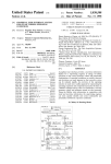
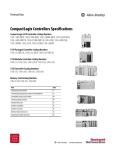
Extract a Part of a Bar Code
For example, a bar code may contain information about a bag on a conveyor at an
airport. To check the flight number and destination of the bag, you extract
characters 10 - 18.
Airline
Bar code
N
W
A
Character number
1
2
3
Origin
4
5
H
O
P
6
7
8
Flight #
9
Destination
5
0
5
8
10
11
12
13
5
0
5
8
14
A
M
S
15
16
17
A
M
S
Date
18
0
2
2
2
0
1
19
20
21
22
23
24
9 characters
EXAMPLE
In the baggage handling conveyor of an airport, each bag gets a bar code. Characters 10 - 18 of the bar
code are the flight number and destination airport of the bag. After the bar code is read (bag_read.EM
is on) the MID instruction copies the flight number and destination airport to the bag_flt_and_dest
tag.
42808
Rockwell Automation Publication 1756-PM013C-EN-P - November 2012
21
Chapter 2
Processing ASCII Characters
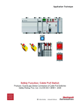
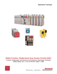
For example, in a sorting operation, an array of a user-defined data type creates a
table that shows the lane number for each type of product. To determine which
lane to route a product, the controller searches the table for the product ID
(characters of the bar code that identify the product).
Look Up a Bar Code
Tag Name
product_id
’GHI’
Value
− sort_table
− sort_table[0]
+ sort_table[0].Product_ID
+ sort_table[0].Lane
− sort_table[1]
+ sort_table[1].Product_ID
+ sort_table[1].Lane
− sort_table[2]
+ sort_table[2].Product_ID
+ sort_table[2].Lane
’ABC’
1
’DEF’
2
’GHI’
lane
3
3
To look up a bar code:
· Create the PRODUCT_INFO Data Type.
· Search for the Characters.
· Identify the Lane Number.
· Reject Bad Characters.
· Enter the Product IDs and Lane Numbers.
TIP
To copy the above components from a sample project, open the samples folder.
For version 20 and earlier:
…\RSLogix 5000\Projects\Samples
For version 21 and later:
…\Users\Public\Documents\Studio 5000\Samples\ENU\[version]\Rockwell Automation
Open this project.
22
Rockwell Automation Publication 1756-PM013C-EN-P - November 2012
Processing ASCII Characters
Chapter 2
Create the PRODUCT_INFO Data Type
To create a new data type:
Create this user-defined data type.
Data Type: PRODUCT_INFO
Name
PRODUCT_INFO
Description
Identifies the destination for an item based on an ASCII string of characters
that identify the item
Members
Name
Data Type
+ Product_ID
STRING
Lane
DINT
Style
Description
ASCII characters that identify the item
Decimal
Destination for the item, based on its ID
Right-click and choose New Data Type.
Search for the Characters
43038
The SIZE instruction:
· Counts the number of elements in the sort_table array (type
PRODUCT_INFO). This array contains the product ID for each item
and the corresponding lane number for the item.
· Counts the number of elements in Dimension 0 of the array. In this
case, that is the only dimension.
· Sets the Length of the subsequent FSC instruction equal to the size of
the sort_table array.
The FSC instruction searches each Product_ID member in the sort_table array
until the instruction finds a match to the product_id tag.
· The sort_table_search tag controls the FSC instruction.
· Although the previous instruction sets the Length of this instruction,
you enter an initial value to verify the project.
· The product_id tag contains the bar code characters that you want to
find.
Rockwell Automation Publication 1756-PM013C-EN-P - November 2012
23
Chapter 2
Processing ASCII Characters
Identify the Lane Number
43038
When the FSC instruction finds the product ID within the sort_table array, the
instruction sets the FD bit. The POS member indicates the element number
within the sort_table array of the match. The corresponding LANE member
indicates the lane number of the match.
Based on the POS value, the MOV instruction moves the corresponding lane
number into the lane tag. The controller uses the value of this tag to route the
item.
After the MOV instruction sets the value of the lane tag, the RES instruction
resets the FSC instruction so it can search for the next product ID.
Reject Bad Characters
43038
If the FSC instruction does not find the product ID within the sort_table array,
the instruction sets the DN bit. The MOV instruction moves 999 into the lane
tag to notify the controller to reject or reroute the item.
After the MOV instruction sets the value of the lane tag, the RES instruction
resets the FSC instruction so it can search for the next product ID.
24
Rockwell Automation Publication 1756-PM013C-EN-P - November 2012
Processing ASCII Characters
Chapter 2
Enter the Product IDs and Lane Numbers
In the sort_table array, enter the ASCII characters to identify each item and the
corresponding lane number for the item.
Tag Name
Value
− sort_table
− sort_table[0]
+ sort_table[0].Product_ID
+ sort_table[0].Lane
− sort_table[1]
+ sort_table[1].Product_ID
+ sort_table[1].Lane
Check the Bar Code Characters
{…}
{…}
ASCII characters that identify the first item
Lane number for the item
{…}
ASCII characters that identify the next item
Lane number for the item
Use a compare instruction (EQU, GEQ, GRT, LEQ, LES, NEQ) to check for
specific characters.
· The hexadecimal values of the characters determine if one string is less than
or greater than another string.
· When the two strings are sorted, as in a telephone directory, the order of
the strings determines which one is greater.
l
e
s
s
e
r
g
r
e
a
t
e
r
ASCII Characters
Hex Codes
1ab
$31$61$62
1b
$31$62
A
$41
AB
$41$42
B
$42
a
$61
ab
$61$62
AB < B
a>B
Use one of these compare instruction:
To see if the string is:
Enter this instruction:
Equal to specific characters
EQU
Not equal to specific characters
NEQ
Greater than specific characters
GRT
Equal to or greater than specific characters
GEQ
Less than specific characters
LES
Equal to or less than specific characters
LEQ
Rockwell Automation Publication 1756-PM013C-EN-P - November 2012
25
Chapter 2
Processing ASCII Characters
For example:
EXAMPLE
When bag_flt_and_dest is equal to gate[1], xfer[1] turns on. This routes the bag to the required gate.
42808
Convert a Value
You can convert the ASCII representation of a value to an DINT or REAL value
that you can use in your application.
· The STOD and STOR instructions skip any initial control or nonnumeric characters (except the minus sign in front of a number).
· If the string contains multiple groups of numbers that are separated by
delimiters (for example, / ), the STOD and STOR instructions convert
only the first group of numbers.
For example, to convert ASCII characters to a floating-point value:
EXAMPLE
After reading the weight from the scale (weight_read.EM is on), the STOR instruction converts the
numeric characters in weight_ascii to a REAL value and stores the result in weight.
42810
For example, to convert ASCII characters to an integer value:
EXAMPLE
When MV_read.EM is on, the STOD instruction converts the first set of numeric characters in
MV_msg to an integer value. The instruction skips the initial control character ($06) and stops at the
delimiter ( \ ).
42620
26
Rockwell Automation Publication 1756-PM013C-EN-P - November 2012
Processing ASCII Characters
Decode an ASCII Message
Chapter 2
You can extract and convert a value from an ASCII message that contains
multiple values. For example, a message may look like this:
First value
[Ctrl-F]
message #
Control character
Second value
Third value
\ F-key
\
F-key action
Delimiter
Delimiter
[CR]
Termination character
Rung A: Find and Convert
a Floating-Point Value
42810
Rung B: Find and Convert
an Integer Value
42810
The FIND instruction locates characters within a string.
· The Source contains the string tag to search.
· The Result contains the location where the FIND instruction locates the
search value you specify.
The MID instruction identifies a group of characters within a string and places
them in their own string tag.
· The source is the same string tag as for the FIND instruction.
· The quantity values tells the MID instruction how many characters to pull
from the source.
· The start value is the same as the Result value from the FIND instruction.
This tells the MID instruction where to start pulling characters from the
Source.
· The Destination contains the characters you located.
Rockwell Automation Publication 1756-PM013C-EN-P - November 2012
27
Chapter 2
Processing ASCII Characters
Build a String
This example builds a string that contains two variables. For example, an operator
terminal may require a string that looks like this:
[Ctrl-F]
message #
Control character
\
address
Delimiter
[CR]
Termination character
· For more variables, use additional INSERT or CONCAT instructions.
· If you need to send a floating-point value, use a RTOS instruction in place
of the DTOS instruction.
· The final string does not include the termination character. When you
send the string, use an AWA instruction to automatically append the
termination character.
EXAMPLE
To trigger a message in a MessageView terminal, the controller sends the terminal a message in this
format: [Ctrl-T] message # \ address [CR]
ATTENTION: When send_msg is on, the rung does this:
· The first DTOS instruction converts the message number to ASCII characters.
· The INSERT instruction inserts the message number (in ASCII) after the control character [CtrlT]. (The hex code for Ctrl-T is $14.)
· The second DTOS instruction converts the node number of the terminal to ASCII characters.
· The CONCAT instruction puts the node number (in ASCII) after the backslash [ \ ] and stores
the final string in msg.
ATTENTION: To send the message, an AWA instruction sends the msg tag and appends the carriage return [CR].
42813
28
Rockwell Automation Publication 1756-PM013C-EN-P - November 2012
ASCII Character Codes
Character
Dec
Hex
Character
Dec
Hex
Character
Dec
Hex
Character
Dec
Hex
[ctrl-@] NUL
0
$00
SPACE
32
$20
@
64
$40
‘
96
$60
[ctrl-A] SOH
1
$01
!
33
$21
A
65
$41
a
97
$61
[ctrl-B] STX
2
$02
“
34
$22
B
66
$42
b
98
$62
[ctrl-C] ETX
3
$03
#
35
$23
C
67
$43
c
99
$63
[ctrl-D] EOT
4
$04
$
36
$24
D
68
$44
d
100
$64
[ctrl-E] ENQ
5
$05
%
37
$25
E
69
$45
e
101
$65
[ctrl-F] ACK
6
$06
&
38
$26
F
70
$46
f
102
$66
[ctrl-G] BEL
7
$07
‘
39
$27
G
71
$47
g
103
$67
[ctrl-H] BS
8
$08
(
40
$28
H
72
$48
h
104
$68
[ctrl-I] HT
9
$09
)
41
$29
I
73
$49
i
105
$69
[ctrl-J] LF
10
$l ($0A)
*
42
$2A
J
74
$4A
j
106
$6A
[ctrl-K] VT
11
$0B
+
43
$2B
K
75
$4B
k
107
$6B
[ctrl-L] FF
12
$0C
,
44
$2C
L
76
$4C
l
108
$6C
[ctrl-M] CR
13
$r ($0D)
-
45
$2D
M
77
$4D
m
109
$6D
[ctrl-N] SO
14
$0E
.
46
$2E
N
78
$4E
n
110
$6E
[ctrl-O] SI
15
$0F
/
47
$2F
O
79
$4F
o
111
$6F
[ctrl-P] DLE
16
$10
0
48
$30
P
80
$50
p
112
$70
[ctrl-Q] DC1
17
$11
1
49
$31
Q
81
$51
q
113
$71
[ctrl-R] DC2
18
$12
2
50
$32
R
82
$52
r
114
$72
[ctrl-S] DC3
19
$13
3
51
$33
S
83
$53
s
115
$73
[ctrl-T] DC4
20
$14
4
52
$34
T
84
$54
t
116
$74
[ctrl-U] NAK
21
$15
5
53
$35
U
85
$55
u
117
$75
[ctrl-V] SYN
22
$16
6
54
$36
V
86
$56
v
118
$76
[ctrl-W] ETB
23
$17
7
55
$37
W
87
$57
w
119
$77
[ctrl-X] CAN
24
$18
8
56
$38
X
88
$58
x
120
$78
[ctrl-Y] EM
25
$19
9
57
$39
Y
89
$59
y
121
$79
[ctrl-Z] SUB
26
$1A
:
58
$3A
Z
90
$5A
z
122
$7A
ctrl-[ ESC
27
$1B
;
59
$3B
[
91
$5B
{
123
$7B
[ctrl-\] FS
28
$1C
<
60
$3C
\
92
$5C
|
124
$7C
ctrl-] GS
29
$1D
=
61
$3D
]
93
$5D
}
125
$7D
[ctrl-^] RS
30
$1E
>
62
$3E
^
94
$5E
~
126
$7E
[ctrl-_] US
31
$1F
?
63
$3F
_
95
$5F
DEL
127
$7F
Rockwell Automation Support
Rockwell Automation provides technical information on the Web to assist you in using its products.
At http://www.rockwellautomation.com/support/, you can find technical manuals, a knowledge base of FAQs, technical and
application notes, sample code and links to software service packs, and a MySupport feature that you can customize to make the
best use of these tools.
For an additional level of technical phone support for installation, configuration, and troubleshooting, we offer TechConnect
support programs. For more information, contact your local distributor or Rockwell Automation representative,
or visit http://www.rockwellautomation.com/support/.
Installation Assistance
If you experience a problem within the first 24 hours of installation, review the information that is contained in this manual.
You can contact Customer Support for initial help in getting your product up and running.
United States or Canada
1.440.646.3434
Outside United States or Canada
Use the Worldwide Locator at http://www.rockwellautomation.com/support/americas/phone_en.html, or contact your local Rockwell
Automation representative.
New Product Satisfaction Return
Rockwell Automation tests all of its products to ensure that they are fully operational when shipped from the manufacturing facility.
However, if your product is not functioning and needs to be returned, follow these procedures.
United States
Contact your distributor. You must provide a Customer Support case number (call the phone number above to obtain one) to your
distributor to complete the return process.
Outside United States
Please contact your local Rockwell Automation representative for the return procedure.
Documentation Feedback
Your comments will help us serve your documentation needs better. If you have any suggestions on how to improve this document,
complete this form, publication RA-DU002, available at http://www.rockwellautomation.com/literature/.
Rockwell Otomasyon Ticaret A.Ş., Kar Plaza İş Merkezi E Blok Kat:6 34752 İçerenköy, İstanbul, Tel: +90 (216) 5698400
Rockwell Automation Publication 1756-PM013C-EN-P - November 2012
Supersedes Publication 1756-PM013B-EN-P - July 2008
Copyright © 2012 Rockwell Automation, Inc. All rights reserved. Printed in the U.S.A.