1
Quick Check Cabinet Mount with Quick Tread
Surface Mounted
Site Specifications
Power Requirements
Air Supply Req. (IS Units)
115/230v, 15 amp* 50/60 Hz 1 phƗ
90-150 PSI (6.2-10.3 bar)
Approximate Air
Consumption
Min. Concrete Spec.
Grout Spec.
25 SCFM @ 90 PSI
(648 Lpm @ 6.2 bar)
3 in. (76 mm) thick,
3000 PSI (20,700kPA) rating
only required when needed to level sensors
Max. Longitudinal Slope
1/4 in. per ft. (21 mm/m)
Max. Lateral Slope
1/16 in. per ft. (5 mm/m)
Pedestal Location
36-96 in. (914-2438 mm) from QT1
Product Specifications
Max. Wheel Weight
Cabinet Mount Quick Check and Quick Tread Installation
Amperage shown is minimal circuit rating.
Isolated ground recommended.
See 6778-T for complete site specifications.
*
Ɨ
3500 lb. (1588 kg) per wheel
Test Entry Speed
2 to 8 mph (3-13 km/h)
Shipping Weight
Quick Check Cabinet
290 lbs (132 kg)
Quick Check Cabinet
Mount Sensor
889 lbs (403 kg)
Quick Tread
530 lbs (241 kg)
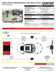
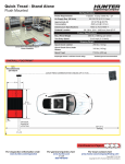
OVERALL FOOTPRINT
15 ft.
RECOMMENDED
BAY WIDTH
QUICK TREAD COMMUNICATION CABLES (UP TO 75 ft.)
DISTANCE OF
LONGEST
WHEELBASE
VEHICLE TO BE
TESTED
(TYPICAL 165 in.)
67 in.
WALL TO
FRONT
WHEEL STOP:
TYPICAL 118 in.
(SPECIFIED
RANGE 126 TO
102 in.)
SENSOR
HEIGHT:
7 ft. 10 in.
4 in.
TYPICAL
RECOMMENDED
BAY LENGTH
30 ft. 2 in.
TO
28 ft. 2 in.
OPTIONAL
PEDESTAL
LOCATION
Continued on Page 2
For inspection information visit:
www.hunter.com/inspection
For general inquiries visit:
www.hunter.com
or call
800 448-6848
For local contact visit:
www.hunter.com/company/findrep.cfm
Form 6892-T, 02-15b
Copyright © 2015, Hunter Engineering Company
Quick Check Cabinet Mount with Quick Tread
Surface Mounted
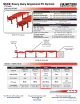
QUICK CHECK DIMENSIONS
96 in.
(8 ft.)
24 1/2 in.
16 1/4 in.
82 in.
(7 ft. 10 in.)
82 in.
(7 ft. 10 in.)
45 1/4 in.
23 1/2 in.
QUICK TREAD DIMENSIONS
PEDESTAL
5 in. 14 7/8 in.
67 in.
(5 ft. 7 in.)
44 in.
(3 ft. 8 in.)
34 1/2 in.
39 in.
(3 ft 3 in.)
5 in.
17 3/8 in.
96 in. (8 ft.) is the maximum distance
between the middle of the pedestal
and nearest edge of Quick Tread.
Any further will reduce max
vehicle test entry speed.
36 to 96 in.
(3 ft. to 8 ft.)
24 in.
(2 ft.)
87 in.
(7 ft. 3 in.)
3 1/2 in.
STACK HEIGHT
OPTIONAL IN-GROUND CONDUIT SPECIFICATIONS
PEDESTAL
RAMP ONE
RAMP TWO
Additional conduit
from pedestal to
console for a Burndy
cable (max length of
75 feet), and two Cat5
cables may also be
desired. Air supply to
pedestal should also be
considered.
Form 6892-T, 02-15b
Copyright © 2015, Hunter Engineering Company