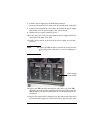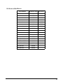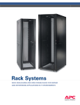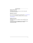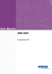
1
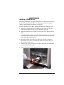
Adding a Disk Drive
The internal disk drives (A upper and B lower) are located in the back of
the SPU. The internal disk drives are hot swapable when the proper
software and hardware procedures are followed.
To add a disk drive in the SPU, perform the following hardware steps:
1. Align the new disk drive into the disk tray and insert the four (2 on
each side) mounting screws to secure the disk to the tray.
2. Align the disk and tray assembly to the empty slot in the back of the
SPU.
3. Carefully slide the disk into the SPU until it firmly seats into the disk
card. Note that the guide tabs on each side of the disk tray fully seat
to the guide pins on the chassis.
4. Angle the bottom of the disk cover plate into the SPU so that the
hooked tabs go over the extended pins inside the chassis. This acts
like a hinge for the cover.
5. Push the top of the cover plate towards the SPU until it is flush with
the chassis and fully seated.
6. Tighten the single, captive mounting screw.
1
Once you have completed the addition of the disk drive, you must
perform the Hot swap procedure:
Hot Swap Software Procedure
NOTE
Step 1.
HP often uses different manufacturers for disks having
the same product number. This hot swap procedure will
not automatically update the disk driver’s internal
manufacturer information to that of the added disk drive.
Do an ioscan on the added disk drive to ensure that it is
accessible an also as a double check that it is a proper
installation. Refer to the above note. For example:
# ioscan /dev/dsk/cXtXdX
Step 2.
Create a physical volume using pvcreate with the -B option. -B
creates an area on the disk for a LIF volume, boot utilities, and
a BDRA (Boot Data Reserved Area). For example,
# pvcreate -B /dev/rdsk/cXtXdX
Step 3.
Create a directory for the volume group using mkdir.
Step 4.
Create a device file named group in the above directory with
the mknod command.
Step 5.
Create the root volume group specifying each physical volume
to be included using vgcreate. For example:
vgcreate /dev/vgroot /dev/dsk/cXtXdX
Step 6.
Use mkboot to place boot utilities in the boot area:
mkboot /dev/rdsk/cXtXdX
Step 7.
Use mkboot -a to add an AUTO file in boot LIF area, for
example:
mkboot -a ‘’hpux (52.3.0;0)/stand/vmunix’’
/dev/rdsk/cXtXdX
Step 8.
2
Create the root logical volume. You must specify contiguous
extents (-C y) with bad block relocation disabled (-r n). For
example,
lvcreate -C y -r n root /dev/vgroot
Step 9.
Extend the mirrors onto the disk you’ve added. For example:
lvextend -m 1 <LV name> /dev/vgroot/root /dev/dsk/cXtXdX
Step 10. Specify that logical volume be used as the root logical volume,
for example:
lvln -r /dev/vgroot/root
At this point you will need to create a file system on the disk. Refer to
your HP-UX system administration documentation.
Hot Swap Procedure for Unattached Physical Volumes
Follow these steps to replace a hot swap disk drive for unattached
physical volumes.
NOTE
Step 1.
HP often uses different manufacturers for disks having
the same product number. This hot swap procedure will
not automatically update the disk driver’s internal
manufacturer information to that of the added disk drive.
Do an ioscan on the replaced disk drive to ensure that it is
accessible an also as a double check that it is a proper
replacement. Refer to the above note. For example:
# ioscan /dev/dsk/c2t4d0
3
Step 2.
Create a physical volume using pvcreate with the -B option. -B
creates an area on the disk for a LIF volume, boot utilities,
and a BDRA (Boot Data Reserved Area). For example:
# pvcreate -B /dev/rdsk/cXtXdX
Step 3.
Create a directory for the volume group using mkdir.
Step 4.
Create a device file named group in the above directory with
the mknod command.
Step 5.
Create the root volume group specifying each physical volume
to be included using vgcreate. For example,
# vgcreate /dev/vgroot /dev/dsk/cXtXdX
Step 6.
Use mkboot to place boot utilities in the boot area:
# mkboot /dev/rdsk/cXtXdX
Step 7.
Use mkboot -a to add an AUTO file in boot LIF area, for
example:
# mkboot -a ‘’hpux (52.3.0;0)/stand/vmunix’’
/dev/rdsk/cXtXdX
Step 8.
Create the root logical volume. You must specify contiguous
extents (-C y) with bad block relocation disabled (-r n). For
example,
# lvcreate -C y -r n root /dev/vgroot
Step 9.
Attach the new disk drive to the active volume group with the
vgchange command.
# vgchange -a y <volume group name>
For example:
# vgchange -a y /dev/vg00
Step 10. After running the mkboot command, do an lvlnboot -R to link
the added disk drive into the boot data reserved area of all the
physical volumes in the volume group.
# lvlnboot -R
Step 11. Create mirrors on the disk you’ve added. For example,
4
lvextend -m 1 <LV name> /dev/vgroot/root /dev/dsk/cXtXdX
Step 12. Synchronize the mirrors. This may take several minutes as it
will have to copy all the data from the original copy of the data
to the mirrored extents. The logical volume(s) are still
accessible to users’ applications during this command.
#vgsync <VG name>
For example:
#vgsync /dev/vg00
At this point the system should be fully functional.
5
6
Adding a Power Supply
Before unpacking the new power supply, inspect the shipping carton for
obvious damage. If damage to the shipping carton is observed, report it to
the carrier immediately.
Carefully unpack the new power supply. Check it for damage. If no
damage is observed, proceed with the instructions that follow. If damage
is noticed, do not install the power supply. Get a replacement power
supply.
WARNING
Be careful lifting the power supply into the SPU, it
weights approximately 7.88 Kg (17.5lbs.).
WARNING
The AC power to the SPU does not have to be
disconnected to add a power supply to the SPU. Also
the power switch on the SPU does not have to be in
the standby position to perform this task.
To add a power supply in the SPU, perform the following steps:
1. Be sure the power switch on the power supply is in the OFF position.
2. Remove the front bezel.
3. Remove the EMI shield.
4. Remove the power supply slot cover in the desired position, by
loosening the two captive screws at the top edge of the cover, then pull
it away from the SPU.
5. Align the power supply with the selected empty slot in the front of the
SPU.
6. Slide the power supply into the SPU while holding the
insertion/extractor lever out (horizontal).
7
7. Push the power supply into the SPU firmly until the
insertion/extractor lever can hook under the extended tab on the SPU.
8. Push the insertion/extractor lever down, flush with the power supply.
This firmly seats the power supply to the system board.
9. Tighten the two captive mounting screws.
10. Be sure the power cord associated with the power supply installed is
connected at the back of the SPU.
11. Put the power switch, on the front of the power supply, in to the ON
position.
NOTE
The power OK LED should be on when the power switch is
in the ON position, and there is a power cord plugged
in.
Power Supply
Power Switch
12. Replace the EMI shield by inserting the tabs on the top of the EMI
shield into the slots chassis just below the front panel. Then push the
EMI shield into the chassis and tighten the two mounting screws on
the bottom.
13. Replace the front bezel by aligning it over the front panel and front of
the chassis and snapping it to the bezel retainer clips along the sides
8
of the chassis.
Once the system is re-assembled, be sure there are no errors on the front
panel or system console. Be sure the system is ready for customer use.
9
10
Upgrading Secure Web Console Firmware
The following paragraphs describe the procedures to upgrade your
Secure Web Console (SWC) firmware.
Secure Web Console Firmware (HP Direct) Upgrade
Procedure
To upgrade the firmware on your SWC proceed as follows:
NOTE
Before upgrading, end any sessions with the SWC using
the [Close Console] menu option.
If direct FTP access is not available (firewall, etc.) refer to
Secure Web Console Firmware Upgrade Using A Local
FTP Server later in this section.
CAUTION
Do not disconnect the SWC power during the upgrade
procedure.
Failure to follow any precautions in this procedure can
result in an incorrectly configured or damaged SWC.
Step 1.
Log into the SWC as Administrator.
Step 2.
Select the [Upgrade] option from the [Support] menu.
Step 3.
The Upgrade Software screen will be displayed, fill in the
following:
• Use the default login, Anonymous (Use your e-mail address
as a password).
• Source System IP address: 192.151.11.37
• File path: /dist/webconsole/XX.X
11
NOTE
Step 4.
NOTE
The path above is for demonstration only. The XX.X at the
end of the example will be filled with the upgrade version
you are installing.
Select [OK] to launch the update process.
As the upgrade progresses, you will see messages about
the files being brought in and written into flash memory.
The files will include:
• APPLICATION.ROM
• BOOTSTRAP.ROM
• RESOURCES.ROM
• upgrade.cnf
If the secure web console already has this version of
firmware, a pop-up window will appear indicating that
Your SWC does not need to be upgraded (Aborted).
If you have a problem reconnecting to the WEB Console
after the Upgrade, make sure the browser's cache is
cleared and restarted by exiting your browser then
restarting it.
Step 5.
Once the process is completed, a pop-up window stating
Upgrade Complete, SWC is now resetting will appear and the
SWC will automatically reboot.
Step 6.
RESET the SWC by cycling power (power off then on again).
Secure Web Console Firmware Upgrade Using A Local
FTP Server
This procedure should be used when direct access to the HP FTP server
is not available (e.g. firewalls).
12
CAUTION
Permanent damage to the product may result if these
instructions are not followed EXACTLY.
CAUTION
The transfer must be done in Binary mode and the local
FTP server must be FTP accessible by the Secure Web
Console.
Do Not transfer the files from HP to the local server in
ASCII mode.
If you do, you will permanently disable the SWC.
Failure to follow this precaution can cause the SWC to
stop working.
This failure is UNRECOVERABLE
Step 7.
Use the HP FTP site (192.151.11.37) and path
(/dist/webconsole/XX.X) to transfer the following files to your
local FTP server in binary mode:
• APPLICATION.ROM
• BOOTSTRAP.ROM
• RESOURCES.ROM
• upgrade.cnf
NOTE
The path above is for demonstration only. The XX.X at the
end of the example will be filled with the upgrade version
you are installing.
13
Step 8.
Using FTP, transfer these files to an empty directory on your
local FTP server.
Ensure that the file and directory permissions are set so that
ALL files can be read by the FTP user.
CAUTION
Ensure that no other files, beside those listed above, are in
the local FTP directory.
If the directory contains extraneous files, it may
permanently damage the Secure Web Console.
Step 9.
14
Perform the upgrade procedure using the [Upgrade] menu
option on the Secure Web Console.
Add-On Memory
Follow these procedures to add memory to an rp7400 server.
Memory Configuration Rules
An rp7400 system supports up to 4 memory carriers (numbered 0, 1, 2,
and 3), each with slots for 4 memory DIMM pairs (numbered 0a/b, 1a/b,
2a/b, and 3a/b). For the DIMMs to work, both DIMMs in a slot pair must
be the same type (i.e., the same part number).
• Performance considerations. For best performance, install
DIMMs evenly among the carriers, loading carriers 0, 1, 2, and 3 in
sequence. For example, four 512MB memory DIMM pairs should be
loaded into slot 0a/b on carrier 0, then slot 0a/b on carrier 1, and so
on.
Although not a requirement for performance, the largest memory
sizes should be installed first, making it more convenient if the
memory DIMMs are re-sequenced at a later time.
• Cooling considerations. The following will help optimize air flow
cooling within the system.
Always install memory carriers in the sequence 0, 1, 2, than 3. For
example, if you have only two memory carriers, make sure they are
installed as carrier 0 and carrier 1.
Install DIMMs into the carriers in the following slot order: 0a/b, 1a/b,
2a/b, 3a/b.
NOTE
The most important rule is that DIMMs of the same type
are distributed evenly amongst the carriers. If necessary,
remove and re-sequence existing memory modules
to balance the distribution; otherwise, a PDC error
may occur.
15
Procedure Overview
1. Remove power from the system.
2. Remove the front bezel.
3. Extend the SPU out the back of the cabinet.
4. Remove the back top cover
5. Remove the back air baffle
6. Remove the memory carrier.
7. Install new memory DIMMs in the memory carrier.
8. Reinstall the memory carrier.
9. Replace the back air baffle
10. Replace the top cover.
11. Slide the SPU back into the cabinet.
12. Replace the front bezel.
13. Power ON the SPU.
14. Verify the installation.
16
Step 1.
CAUTION
Remove Power From the System
Before starting any shut down type procedures, be sure to
check with the System Administrator or customer to
ensure a system backup has been performed recently.
To shut down and power off the rp7400 computer system,
perform the following steps.
a. Stop all active applications.
b. Perform a normal Operating System shut down, informing
all logged on users of the impending shut down.
c. Once the Operating system has halted, put the power
switch in the standby (0) position.
CAUTION
With the power switch in the standby position, there is
still power to the inside of the SPU.
d. Remove A.C. from the SPU by unplugging the power cords
(up to 3) from the back of the SPU.
Step 2.
Remove the Front Bezel
a. Grasp the front bezel on each side.
b. Pull the front bezel away from the cabinet.
Step 3.
CAUTION
Extend the SPU out the Back of the Cabinet
Be aware of the cables at the back of the SPU while
moving the SPU in or out of the cabinet.
To extend the SPU out the back of the cabinet:
a. Remove the four (two on each side) retainer screws, holding
the bezel flange to the cabinet vertical post.
17
b. Carefully extend the SPU out the front of the cabinet
approximately 2 to 4 inches.
c. Loosen the six (three on each side) mounting screws
holding the bezel brackets to the side of the SPU.
d. Lift the bezel bracket up and off the SPU chassis. Be sure
that both left and right side brackets are removed.
e. Be sure the rear door is open and does not swing closed
during the SPU movement. If necessary the rear door can
be removed
f. Carefully extend the SPU out the back of the cabinet until
the stops on the rails halt reward motion.
18
NOTE
It is recommended that you pull the SPU from the back of
the cabinet. This allows you to monitor the cable
movement to avoid snags and tangles with other SPUs or
cables.
The SPU should now be fully extended out the back of the
cabinet.
WARNING
Step 4.
CAUTION
Only extend one SPU at a time. Never attempt to
extend more that one SPU for any reason.
Remove the Back Top Cover
Operating the system without the back top cover in place
can make the SPU susceptible to EMI problems. Replace
the back top cover before operating the system.
To remove a back top cover from the SPU:
a. Loosen the two captive screws along the back edge of the
top cover.
b. Lift the back edge of the top cover up and away from the
SPU
Step 5.
CAUTION
Remove the Back Air Baffle
Operating the system without the back air baffle will
create air flow problems and possibly shorten the life of
the internal components. Hewlett-Packard does not
recommend the system be powered on with the air baffles
removed. Also, operation of the system without the top
cover and air baffle in place can make the system
19
susceptible to EMI problems.
To remove the back air baffle from the:
a. Loosen the two captive mounting screws at the support
bridge.
b. Grasp the air baffle along the extruded handle on the back
edge of the air baffle and lift it out of the SPU.
Step 6.
Remove the Memory Carrier
The memory carriers (up to four) are located along the back of
the SPU.
CAUTION
Be sure to have an anti-static pad or ESD compliant work
place to rest the memory carrier on.
To remove the memory carrier from the SPU:
a. Grasp the insertion/extractor levers on the appropriate
memory carrier and pull them up to disengage the memory
carrier form the system board.
b. Carefully pull the memory carrier out of the SPU.
Step 7.
Install the Memory DIMMs in the Memory Carrier
The memory DIMM resides in slots located on the memory
carrier. The memory DIMMs are loaded in DIMM pairs.
Memory DIMMs are keyed and only install into a memory
carrier one way. Memory DIMMs are only installed in matched
(memory size) pairs. Be sure the memory DIMM being
installed is matched to the appropriate DIMM in the pair slot.
To add a memory DIMM in the memory carrier:
a. Align the memory DIMM over the correct memory carrier
slot. Be sure the extractor levers are in the open position
(angled out from the memory slot).
b. Firmly and evenly (pressure on both ends of the memory
20
DIMM) press the memory DIMM into the memory carrier
slot until the memory DIMM fully seats and the extractor
levers are up against the outside edges of the memory
DIMM.
c. Pick up the memory carrier and visually check to see that
all memory DIMMs are seated fully. No memory DIMM
card edge should be higher than the others. This indicates
that a memory DIMM is not fully seated into the memory
carrier slot. Press firmly on the raised edge to seat the
memory DIMM into its’ socket.
d. Replace the memory DIMM hold down bracket.
Step 8.
Replace the Memory Carrier
The memory carriers (up to four) are located along the back of
the SPU. Memory carriers are installed from slot 0 through
slot 3 (slot 0 is the right most slot facing the back of the SPU).
To replace the memory carrier in the SPU:
a. While holding the memory carrier by the extended
insertion/extractor levers, align the memory carrier with
the appropriate slot card guides on the system board.
b. Carefully lower the memory carrier into the card guides,
until the insertion/extractor levers hook under the card
guide edges.
c. Press the insertion/extractor levers down until the memory
carrier firmly seats into the system board. The
insertion/extractor levers should be parallel with the
memory carrier edge.
Step 9.
CAUTION
Replace the Back Air Baffle
Operating the SPU without the back air baffle will create
air flow problems and possibly shorten the life of the
internal components. Hewlett-Packard does not
recommend the SPU be powered on with the air baffles
removed. Also, operation of the SPU without the top cover
and air baffle in place can make the SPU susceptible to
21
EMI problems.
To replace the back air baffle in the SPU:
a. Angle the back edge of the air baffle onto the support
bridge flange, then lower the air baffle over the CPU
cooling towers (up to four).
CAUTION
Be sure all CPU cooling tower tops are centered in the
support brackets. The support brackets have enough
play in them to allow proper alignment.
b. Be sure the air baffle sits flush into the SPU.
c. Tighten the two captive screws at the support bridge.
Step 10. Replace the Back Top Cover
To replace the back top cover in the SPU:
a. Angle the back edge of the top cover into the support
bridge. Be sure the tabs at the back edge of the top cover
insert into the slots on the support bridge.
b. Lower the top cover onto the SPU. Firmly press the top
cover down onto the SPU, making sure the outer edges of
the top cover are over the top edges of the chassis.
c. Tighten the two captive screws.
Step 11. Insert the SPU Back into the Cabinet
CAUTION
Be aware of the cables at the back of the SPU while
moving the SPU in or out of the cabinet.
To insert the SPU into the cabinet from the back:
a. Press the rail slide locks (one on each side) to release the
rail locks while gently pushing the SPU forward.
b. Carefully insert the SPU all the way into the cabinet until
22
the front of the SPU sticks out approximately 2 to 4 inches.
NOTE
It is recommended that you push the SPU from the back of
the cabinet. This allows you to monitor the cable
movement to avoid snags and tangles with other SPUs
or cables.
c. Align the left and right bezel bracket key slots over the
three bracket screws on each side of the SPU.
d. Slide the bezel brackets down and tighten the six (three on
each side) bracket screws.
e. Carefully push the SPU back into the cabinet until the
bezel brackets contact the cabinet vertical rails.
f. Insert the four (two on each side, T25) SPU retainer
screws, located just below and above bezel snap tabs.
Check all cables to be sure none have been loosened during the
previous procedure. Close or replace the rear door.
23
Step 12. Replace the Front Bezel
To replace the front bezel, perform the following steps:
a. Align the front bezel over the front of the SPU.
b. Press the front bezel onto the cabinet until it snaps into
place.
Step 13. Power the System On
CAUTION
Before applying A.C. power to an rp7400 computer, be sure
all covers and cooling fans are properly installed. Failure
to perform this check could result in decreased computer
component life and reliability.
a. Be sure all connected peripherals are on, with no errors or
faults indicated.
b. Be sure the SPU power switch is in the standby (0)
position.
CAUTION
When the power cords are connected to the SPU, there will
be power present inside the SPU chassis, even with the
power switch in the standby position.
c. Carefully insert the A.C. power cords (3) into the line filter
receptacles at the back of the SPU.
NOTE
Be sure to plug all three power cords into the back of the
SPU. Also be sure the cabinet PDU is plugged into an
appropriate wall outlet.
d. Put the power switch in the on (|) position. At this time
you will hear the cooling fans coming up to speed and being
synchronized. This creates a high pitched squeak for a few
seconds. The fans should drop to normal speed within a few
seconds. If not check the front panel or console for fault
24
indications.
e. Check all front panel LEDs for normal indications, with no
warnings ar faults indicated.
The SPU should take a few minutes to perform all selftests
and initialization routines. At the end of this you should be
able to launch the operating system or initiate other software
routines.
Step 14. Verify the Installation
Issue the ME command in the boot console handler to verify
the system recognizes the new memory configuration.
25
26
Add I/O Cards
The rp7400 server has 12 expansion I/O slots accessible through side panels on the rear of the SPU chassis.
Six slots are located on each of the two sides.
Slots 3 through 12 are “TwinTurbo” slots supporting 66MHz, 64-bit I/O cards. Slots 1 and 2 are “Turbo”
slots supporting cards with lower speed and bandwidth. If higher speed cards are installed in slots 1 or 2,
they will function but their performance will be reduced. Similarly, slower cards can be installed in slots 3
through 12, but their performance will not be improved.
There are two configuration rules to consider:
• Load the slowest cards in slots 1 and 2.
• When possible, balance the total number of PCI cards between the two sides. E.g., when adding four PCI
cards, install two on the right (slots 1 through 6) and two on the left (slots 7 through 12).
CAUTION
If you are installing the A3783A 10/100Base-TX LAN card, do not connect any type of MAU
transceiver to the AUI connector while the system is powered up. Doing so will cause power
to be shut off to the I/O slot and will generate a High Priority Machine Check (HPMC) error.
If you are going to connect a MAU transceiver to this card’s AUI connector, make sure the
system is powered down first. When the system is powered back on, this connection will then
not generate an error condition.
Refer to the instructions shipped with this LAN card for further information.
Procedure Overview
1. Remove power from the system
2. Remove the front bezel
3. Extend the SPU out the back of the system
4. Remove the PCI slot cover
5. Insert the new PCI card
6. Replace the PCI slot cover
7. Slide the SPU back into the cabinet
8. Replace the front bezel
9. Power the system back on
10. Verify the procedure
27
Step 1.
CAUTION
Remove Power from the System.
Before starting any shut down type procedures, be sure to check with the System
Administrator or customer to ensure a system backup has been performed recently.
To shut down and power off the N Class computer system, perform the following steps.
a. Stop all active applications.
b. Perform a normal Operating System shut down, informing all logged on users of the
impending shut down.
c. Put the power switch in the standby position.
CAUTION
With the power switch in the standby position, there is still power to the inside of the SPU.
d. Remove A.C. from the SPU by unplugging the power cords (up to 3) from the back of the SPU.
Step 2.
Remove the Front Bezel
a. Grasp the front bezel on each side.
b. Pull the front bezel away from the cabinet.
Step 3.
CAUTION
Extend the SPU out the Back of the System
Be aware of the cables at the back of the SPU while moving the SPU in or out of the cabinet.
To extend the SPU out the back of the cabinet:
a. Remove the four (two on each side) retainer screws, holding the bezel flange to the cabinet
vertical post.
b. Carefully extend the SPU out the front of the cabinet approximately 2 to 4 inches.
c. Loosen the six (three on each side) mounting screws holding the bezel brackets to the side of
the SPU.
d. Lift the bezel bracket up and off the SPU chassis. Be sure that both left and right side
brackets are removed.
e. Be sure the rear door is open and does not swing closed during the SPU movement. If
necessary the rear door can be removed
f. Carefully extend the SPU out the back of the cabinet until the stops on the rails halt
rearward motion.
NOTE
It is recommended that you pull the SPU from the back of the cabinet. This allows you to
monitor the cable movement to avoid snags and tangles with other SPUs or cables.
The SPU should now be fully extended out the back of the cabinet.
28
WARNING
Step 4.
NOTE
Only extend one SPU at a time. Never attempt to extend more that one SPU for any
reason.
Remove the PCI Cover Plate
Steps 4 through 8 apply to the six PCI card slots on either side of the SPU. As viewed from
the rear of the cabinet, slots 1 through 6 are on the left side. The lowermost slot in the array
is slot 1. Slots 7 through 12 are on the right side, with slot 7 being the lowermost slot in the
array.
a. Loosen the two captive screws at the end of the I/O card slot cover.
b. Swing the cover away and off of the SPU.
Step 5.
NOTE
Insert the I/O Card Into the Slot
The PCI card slots have separators which protect against touching adjacent cards when
plugging in PCI cards. The separators also have tabs which facilitate removing the cards.
a. Remove the metal slot cover, if present, at the rear of the SPU.
b. Align the PCI card with the appropriate slot.
c. Insert the PCI card into the card cage, between the separator/extractor cards.
d. Press firmly on the PCI card to be sure it is fully seated.
Step 6.
Replace the PCI Cover Plate
a. Swing the I/O slot cover closed.
b. Tighten the two captive screws at the end of the slot cover.
NOTE
Step 7.
CAUTION
The PCI card slots have separators which protect against touching adjacent cards when
plugging in PCI cards. The separators also have tabs which facilitate removing the cards.
Insert the SPU Back Into the Cabinet
Be aware of the cables at the back of the SPU while moving the SPU in or out of the cabinet.
To insert the SPU into the cabinet from the back:
a. Carefully insert the SPU all the way into the cabinet until the front of the SPU sticks out the
front approximately 2 to 4 inches.
b. Align the left and right bezel bracket key slots over the three bracket screws on each side of
the SPU.
c. Slide the bezel brackets down and tighten the six (three on each side) bracket screws.
d. Carefully push the SPU back into the cabinet until the bezel brackets contact the cabinet
vertical rails.
29
e. Insert the four (two on each side, T25) SPU retainer screws, located just below and above
bezel snap tabs.
Check all cables to be sure none have been loosened during the previous procedure. Close or
replace the rear door.
Step 8.
Replace the Front Bezel
To replace the front bezel, perform the following steps:
a. Align the front bezel over the front of the SPU.
b. Press the front bezel onto the cabinet until it snaps into place.
Step 9.
CAUTION
Power the System On
Before applying A.C. power to an rp7400 computer, be sure all covers and cooling fans are
properly installed. Failure to perform this check could result in decreased computer
component life and reliability.
a. Be sure all connected peripherals are on, with no errors or faults indicated.
b. Be sure the SPU power switch is in the standby (0) position.
CAUTION
When the power cords are connected to the SPU, there will be power present inside the SPU
chassis, even with the power switch in the standby position.
c. Carefully insert the A.C. power cords (3) into the line filter receptacles at the back of the SPU.
NOTE
Be sure to plug all three power cords into the back of the SPU. Also be sure the cabinet PDU
is plugged into an appropriate wall outlet.
d. Put the power switch in the on (|) position. At this time you will hear the cooling fans coming
up to speed and being synchronized. This creates a high pitched squeak for a few seconds. The
fans should drop to normal speed within a few seconds. If not check the front panel or console
for fault indications.
e. Check all front panel LEDs for normal indications, with no warnings ar faults indicated.
The SPU should take a few minutes to perform all selftests and initialization routines. At the
end of this you should be able to launch the operating system or initiate other software routines.
Step 10. Verify the Procedure
Run the ioscan utility to ensure the system recognizes the I/O card.
30
I/O Scan-to-Slot Matrix
Slot Number
Hardware Path
Slot Type
1
0/5/0
2xPCI
2
0/5/0
2xPCI
3
0/4/0
4xPCI
4
0/8/0
4xPCI
5
0/10/0
4xPCI
6
0/2/0
4xPCI
7
1/12/0
4xPCI
8
1/10/0
4xPCI
9
1/4/0
4xPCI
10
1/2/0
4xPCI
11
1/8/0
4xPCI
12
1/0/0
4xPCI
Core I/O 10/100 base T
0/0/0/0
Core I/O ext SCSI
0/0/1/0
Core I/O Int SCSI
0/0/2/0
Core I/O GSP
0/0/4/0
Core I/O UPS
0/0/5/0
31