1
HP Ultrium tape drives
Technical reference manual
Generation 3 drives
Volume 3—the SCSI interface
Part Number: Q1530–90901 Volume 3
Edition 6, December 2004
<Bold Header>
Legal and notice information
© Copyright 2000–2004—Hewlett-Packard Development Company, L.P.
The information contained in this document is subject to change without notice.
Hewlett-Packard makes no warranty of any kind with regard to this material, including, but not limited to, the implied warranties of
merchantability and fitness for a particular purpose. Hewlett-Packard shall not be liable for errors contained herein or direct,
indirect, special, incidental or consequential damages in connection with the furnishing, performance, or use of this document.
This document contains proprietary information which is protected by copyright. All rights reserved. No part of this document may
be photocopied, reproduced or translated to another language without the prior written consent of Hewlett-Packard.
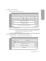
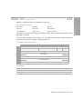
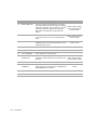
Revision history
Version
Date
Changes
Edition 1
Nov. 2000
All
Edition 2
Mar. 2001
Addition of Read and Write attribute commands and Drive Error Codes
Edition 3
May 2002
Inclusion of the Request Block Address command and the Control mode page, together
with numerous small changes
Edition 5
July 2003
Many small changes
Edition 6
December 2004
Generation 3 version
This document is frequently revised and updated. To find out if there is a later version, please ask your HP OEM Representative.
<Bold Header>
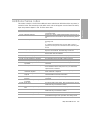
Related documents . . . . . . . . . . . . . . . . . . . .
Documents specific to HP Ultrium drives .
Documentation map . . . . . . . . . . . . . .
General documents and standardization
....................
....................
....................
....................
...
...
...
...
...
...
...
...
....
....
....
....
...
...
...
...
. 7
. 7
. 7
10
The SCSI interface . . . . . . . . . . . . . . . . . . . . . . . . . . . . . . . . . . . . . . . . . . . . . . . . . . . . .
Supported messages . . . . . . . . . . . . . . . . . . . . . . . . . . . . . . . . . . . . . . . . . . . . . . . . .
Supported commands. . . . . . . . . . . . . . . . . . . . . . . . . . . . . . . . . . . . . . . . . . . . . . . . .
SCSI features . . . . . . . . . . . . . . . . . . . . . . . . . . . . . . . . . . . . . . . . . . . . . . . . . . . . . . . . .
Design approach . . . . . . . . . . . . . . . . . . . . . . . . . . . . . . . . . . . . . . . . . . . . . . . . . . . .
Power-on . . . . . . . . . . . . . . . . . . . . . . . . . . . . . . . . . . . . . . . . . . . . . . . . . . . . . . . . .
Reset strategy . . . . . . . . . . . . . . . . . . . . . . . . . . . . . . . . . . . . . . . . . . . . . . . . . . . . . .
Abort handling . . . . . . . . . . . . . . . . . . . . . . . . . . . . . . . . . . . . . . . . . . . . . . . . . . . . .
LUN identification (parallel SCSI only) . . . . . . . . . . . . . . . . . . . . . . . . . . . . . . . . . . . . . . .
Bus parity or CRC errors . . . . . . . . . . . . . . . . . . . . . . . . . . . . . . . . . . . . . . . . . . . . . . .
Disconnect strategy . . . . . . . . . . . . . . . . . . . . . . . . . . . . . . . . . . . . . . . . . . . . . . . . . .
Multi-initiator support . . . . . . . . . . . . . . . . . . . . . . . . . . . . . . . . . . . . . . . . . . . . . . . . .
Fibre Channel operation . . . . . . . . . . . . . . . . . . . . . . . . . . . . . . . . . . . . . . . . . . . . . . . . .
Fibre Channel addressing . . . . . . . . . . . . . . . . . . . . . . . . . . . . . . . . . . . . . . . . . . . . . .
Field replaceable units . . . . . . . . . . . . . . . . . . . . . . . . . . . . . . . . . . . . . . . . . . . . . . . . . .
CD-ROM emulation. . . . . . . . . . . . . . . . . . . . . . . . . . . . . . . . . . . . . . . . . . . . . . . . . . . . .
11
11
12
13
13
13
13
14
15
15
16
17
18
18
20
21
1 Interface Implementation
2 Messages
Message Out support . . . . . . . . . .
Message In support . . . . . . . . . . .
Extended Message support . . .
Status . . . . . . . . . . . . . . . . . . . . . . .
...
...
...
...
...
...
...
...
....
....
....
....
...
...
...
...
...
...
...
...
...
...
...
...
....
....
....
....
...
...
...
...
...
...
...
...
...
...
...
...
....
....
....
....
.
.
.
.
..
..
..
..
23
24
25
26
Summary . . . . . . . . . . . . . . . . . . . . . . . . . . . . . . . . . . . . . . . . . . . . . . . . . . . . . . . . . . . .
Command details . . . . . . . . . . . . . . . . . . . . . . . . . . . . . . . . . . . . . . . . . . . . . . . . . . . . . .
Pre-execution checks . . . . . . . . . . . . . . . . . . . . . . . . . . . . . . . . . . . . . . . . . . . . . . . . . . . .
Bad LUN check . . . . . . . . . . . . . . . . . . . . . . . . . . . . . . . . . . . . . . . . . . . . . . . . . . . . .
Deferred Error check . . . . . . . . . . . . . . . . . . . . . . . . . . . . . . . . . . . . . . . . . . . . . . . . .
Diagnostic Status check . . . . . . . . . . . . . . . . . . . . . . . . . . . . . . . . . . . . . . . . . . . . . . .
Fixed Bit check . . . . . . . . . . . . . . . . . . . . . . . . . . . . . . . . . . . . . . . . . . . . . . . . . . . . .
Flag Link check . . . . . . . . . . . . . . . . . . . . . . . . . . . . . . . . . . . . . . . . . . . . . . . . . . . . .
29
29
30
30
30
31
31
31
3 Commands—introduction
Contents
3
Contents
Contents
Illegal Command check . . . . . . . . . . . . . . . . . . . . . . . . . . . . . . . . . . . . . . . . . . . . . . . . 31
Illegal Field/Request check . . . . . . . . . . . . . . . . . . . . . . . . . . . . . . . . . . . . . . . . . . . . . . 31
Media Access check . . . . . . . . . . . . . . . . . . . . . . . . . . . . . . . . . . . . . . . . . . . . . . . . . . 32
Media Information check . . . . . . . . . . . . . . . . . . . . . . . . . . . . . . . . . . . . . . . . . . . . . . . 33
Media Write check . . . . . . . . . . . . . . . . . . . . . . . . . . . . . . . . . . . . . . . . . . . . . . . . . . . 33
Parameter List check. . . . . . . . . . . . . . . . . . . . . . . . . . . . . . . . . . . . . . . . . . . . . . . . . . . 34
Reservation check . . . . . . . . . . . . . . . . . . . . . . . . . . . . . . . . . . . . . . . . . . . . . . . . . . . . 34
Unit Attention check . . . . . . . . . . . . . . . . . . . . . . . . . . . . . . . . . . . . . . . . . . . . . . . . . . . 34
Command descriptor block . . . . . . . . . . . . . . . . . . . . . . . . . . . . . . . . . . . . . . . . . . . . . . . . 35
4 Commands
ERASE . . . . . . . . . . . . . . . . . . . . . . . . . . . . . . . . . . . . . . . . . . . . . . . . . . . . . . . . . . 19h 38
INQUIRY . . . . . . . . . . . . . . . . . . . . . . . . . . . . . . . . . . . . . . . . . . . . . . . . . . . . . . . . . 12h 39
INQUIRY data pages . . . . . . . . . . . . . . . . . . . . . . . . . . . . . . . . . . . . . . . . . . . . . . . . . . 40
Vital Product Data pages . . . . . . . . . . . . . . . . . . . . . . . . . . . . . . . . . . . . . . . . . . . . . . . 44
Supported Vital Product Data Pages page . . . . . . . . . . . . . . . . . . . . . . . . . . . . . . . . . 44
Unit Serial Number page 45
Device Identification page . . . . . . . . . . . . . . . . . . . . . . . . . . . . . . . . . . . . . . . . . . . . 45
Defined identifiers. . . . . . . . . . . . . . . . . . . . . . . . . . . . . . . . . . . . . . . . . . . . . . . . . . 46
Extended INQUIRY Data VPD page . . . . . . . . . . . . . . . . . . . . . . . . . . . . . . . . . . . . . 48
Sequential Access Device Capabilities page . . . . . . . . . . . . . . . . . . . . . . . . . . . . . . . 48
Drive Component Revision Levels pages . . . . . . . . . . . . . . . . . . . . . . . . . . . . . . . . . . 49
LOAD/UNLOAD . . . . . . . . . . . . . . . . . . . . . . . . . . . . . . . . . . . . . . . . . . . . . . . . . . . 1Bh 50
LOCATE . . . . . . . . . . . . . . . . . . . . . . . . . . . . . . . . . . . . . . . . . . . . . . . . . . . . . . . . . 2Bh 53
LOG SELECT . . . . . . . . . . . . . . . . . . . . . . . . . . . . . . . . . . . . . . . . . . . . . . . . . . . . . . 4Ch 55
LOG SENSE . . . . . . . . . . . . . . . . . . . . . . . . . . . . . . . . . . . . . . . . . . . . . . . . . . . . . . 4Dh 57
Log page format . . . . . . . . . . . . . . . . . . . . . . . . . . . . . . . . . . . . . . . . . . . . . . . . . . . . . 58
Supported Log Pages page . . . . . . . . . . . . . . . . . . . . . . . . . . . . . . . . . . . . . . . . . . . . . . 59
Write Error Counters log page . . . . . . . . . . . . . . . . . . . . . . . . . . . . . . . . . . . . . . . . . . . 60
Read Error Counters log page . . . . . . . . . . . . . . . . . . . . . . . . . . . . . . . . . . . . . . . . . . . . 60
Sequential Access Device log page . . . . . . . . . . . . . . . . . . . . . . . . . . . . . . . . . . . . . . . . 61
Temperature log page . . . . . . . . . . . . . . . . . . . . . . . . . . . . . . . . . . . . . . . . . . . . . . . . . 62
DTD Status log page . . . . . . . . . . . . . . . . . . . . . . . . . . . . . . . . . . . . . . . . . . . . . . . . . . 62
Very High Frequency Data (VHF) . . . . . . . . . . . . . . . . . . . . . . . . . . . . . . . . . . . . . . . 63
Very High Frequency Polling Delay . . . . . . . . . . . . . . . . . . . . . . . . . . . . . . . . . . . . . . 64
DTD Primary Port Status . . . . . . . . . . . . . . . . . . . . . . . . . . . . . . . . . . . . . . . . . . . . . . 64
TapeAlert log page . . . . . . . . . . . . . . . . . . . . . . . . . . . . . . . . . . . . . . . . . . . . . . . . . . . 65
Tape Usage log page . . . . . . . . . . . . . . . . . . . . . . . . . . . . . . . . . . . . . . . . . . . . . . . . . 67
Tape Capacity log page. . . . . . . . . . . . . . . . . . . . . . . . . . . . . . . . . . . . . . . . . . . . . . . . 68
Data Compression log page . . . . . . . . . . . . . . . . . . . . . . . . . . . . . . . . . . . . . . . . . . . . . 68
Performance Data log page . . . . . . . . . . . . . . . . . . . . . . . . . . . . . . . . . . . . . . . . . . . . . 69
Device Status log page. . . . . . . . . . . . . . . . . . . . . . . . . . . . . . . . . . . . . . . . . . . . . . . . . 70
MODE SELECT . . . . . . . . . . . . . . . . . . . . . . . . . . . . . . . . . . . . . . . . . . . . . . . . 15h/55h 71
Mode parameter pages . . . . . . . . . . . . . . . . . . . . . . . . . . . . . . . . . . . . . . . . . . . . . . . . 72
Mode page representation. . . . . . . . . . . . . . . . . . . . . . . . . . . . . . . . . . . . . . . . . . . . 73
Mode data format. . . . . . . . . . . . . . . . . . . . . . . . . . . . . . . . . . . . . . . . . . . . . . . . . . 73
Mode block descriptor . . . . . . . . . . . . . . . . . . . . . . . . . . . . . . . . . . . . . . . . . . . . . . . . . 76
4
Contents
Contents
5
Contents
Read-Write Error Recovery mode page. . . . . . . . . . . . . . . . . . . . . . . . . . . . . . . . . . . . . 76
Disconnect-Reconnect page. . . . . . . . . . . . . . . . . . . . . . . . . . . . . . . . . . . . . . . . . . . . . 78
SCSI drives . . . . . . . . . . . . . . . . . . . . . . . . . . . . . . . . . . . . . . . . . . . . . . . . . . . . . 78
Control mode page . . . . . . . . . . . . . . . . . . . . . . . . . . . . . . . . . . . . . . . . . . . . . . . . . . 79
Data Compression Characteristics page . . . . . . . . . . . . . . . . . . . . . . . . . . . . . . . . . . . . 79
Device Configuration page . . . . . . . . . . . . . . . . . . . . . . . . . . . . . . . . . . . . . . . . . . . . . 81
Medium Partitions mode page . . . . . . . . . . . . . . . . . . . . . . . . . . . . . . . . . . . . . . . . . . . 83
Fibre Channel Logical Unit Control mode page . . . . . . . . . . . . . . . . . . . . . . . . . . . . . . . 84
SCSI LUN Control mode page . . . . . . . . . . . . . . . . . . . . . . . . . . . . . . . . . . . . . . . . . . . 84
Fibre Channel Port Control mode page. . . . . . . . . . . . . . . . . . . . . . . . . . . . . . . . . . . . . 85
SCSI Port Control Mode page . . . . . . . . . . . . . . . . . . . . . . . . . . . . . . . . . . . . . . . . . . . 87
Normal page . . . . . . . . . . . . . . . . . . . . . . . . . . . . . . . . . . . . . . . . . . . . . . . . . . . . 87
Sub-pages . . . . . . . . . . . . . . . . . . . . . . . . . . . . . . . . . . . . . . . . . . . . . . . . . . . . . . 87
Information Exceptions mode page . . . . . . . . . . . . . . . . . . . . . . . . . . . . . . . . . . . . . . . 91
Device Time mode page . . . . . . . . . . . . . . . . . . . . . . . . . . . . . . . . . . . . . . . . . . . . . . . 92
CD-ROM Emulation/Disaster Recovery mode page . . . . . . . . . . . . . . . . . . . . . . . . . . . . 94
MODE SENSE . . . . . . . . . . . . . . . . . . . . . . . . . . . . . . . . . . . . . . . . . . . . . . . . . 1Ah/5Ah 96
PERSISTENT RESERVE IN . . . . . . . . . . . . . . . . . . . . . . . . . . . . . . . . . . . . . . . . . . . . . . 5Eh 98
PERSISTENT RESERVE OUT . . . . . . . . . . . . . . . . . . . . . . . . . . . . . . . . . . . . . . . . . . . 5Fh 101
Additional parameter data . . . . . . . . . . . . . . . . . . . . . . . . . . . . . . . . . . . . . . . . . . 103
PREVENT/ALLOW MEDIUM REMOVAL. . . . . . . . . . . . . . . . . . . . . . . . . . . . . . . . . . . 1Eh 105
READ . . . . . . . . . . . . . . . . . . . . . . . . . . . . . . . . . . . . . . . . . . . . . . . . . . . . . . . . . . 08h 106
READ 6 (CD-ROM mode) . . . . . . . . . . . . . . . . . . . . . . . . . . . . . . . . . . . . . . . . . . . . . . 08h 109
READ 10 (CD-ROM mode) . . . . . . . . . . . . . . . . . . . . . . . . . . . . . . . . . . . . . . . . . . . . . 28h 110
READ ATTRIBUTE . . . . . . . . . . . . . . . . . . . . . . . . . . . . . . . . . . . . . . . . . . . . . . . . . . 8Ch 111
MAM attribute data . . . . . . . . . . . . . . . . . . . . . . . . . . . . . . . . . . . . . . . . . . . . . . . . . 115
Attribute ID values 116
Standard device type attributes. . . . . . . . . . . . . . . . . . . . . . . . . . . . . . . . . . . . . . . 116
Standard medium type attributes. . . . . . . . . . . . . . . . . . . . . . . . . . . . . . . . . . . . . . 118
Standard host type attributes . . . . . . . . . . . . . . . . . . . . . . . . . . . . . . . . . . . . . . . . 118
READ BLOCK LIMITS . . . . . . . . . . . . . . . . . . . . . . . . . . . . . . . . . . . . . . . . . . . . . . . .05h 120
READ BUFFER . . . . . . . . . . . . . . . . . . . . . . . . . . . . . . . . . . . . . . . . . . . . . . . . . . . . 3Ch 121
READ CAPACITY (CD-ROM mode) . . . . . . . . . . . . . . . . . . . . . . . . . . . . . . . . . . . . . . . 25h 124
Read Capacity data . . . . . . . . . . . . . . . . . . . . . . . . . . . . . . . . . . . . . . . . . . . . . . 124
READ MEDIA SERIAL NUMBER . . . . . . . . . . . . . . . . . . . . . . . . . . . . . . . . . . . . . . . . .ABh 125
READ POSITION . . . . . . . . . . . . . . . . . . . . . . . . . . . . . . . . . . . . . . . . . . . . . . . . . . .34h 127
READ TOC (CD-ROM mode). . . . . . . . . . . . . . . . . . . . . . . . . . . . . . . . . . . . . . . . . . . . 43h 131
Read TOC data 132
RECEIVE DIAGNOSTICS RESULTS . . . . . . . . . . . . . . . . . . . . . . . . . . . . . . . . . . . . . . 1Ch 133
RELEASE UNIT . . . . . . . . . . . . . . . . . . . . . . . . . . . . . . . . . . . . . . . . . . . . . . . . . 17h/57h 135
REPORT DENSITY SUPPORT. . . . . . . . . . . . . . . . . . . . . . . . . . . . . . . . . . . . . . . . . . . 44h 137
REPORT DEVICE IDENTIFIER. . . . . . . . . . . . . . . . . . . . . . . . . . . . . . . . . . . . . . . . . . . A3h 140
REPORT LUNS . . . . . . . . . . . . . . . . . . . . . . . . . . . . . . . . . . . . . . . . . . . . . . . . . . . . A0h 141
REPORT SUPPORTED OPCODES . . . . . . . . . . . . . . . . . . . . . . . . . . . . . . . . . . . . . . . A0h 143
REPORT SUPPORTED TASK MANAGEMENT FUNCTIONS . . . . . . . . . . . . . . . . . . . . . A3h 145
REQUEST SENSE . . . . . . . . . . . . . . . . . . . . . . . . . . . . . . . . . . . . . . . . . . . . . . . . . . .03h 147
Request Sense data . . . . . . . . . . . . . . . . . . . . . . . . . . . . . . . . . . . . . . . . . . . . . . . . . 148
Fixed format. . . . . . . . . . . . . . . . . . . . . . . . . . . . . . . . . . . . . . . . . . . . . . . . . . . . . 148
Descriptor format 152
Sense data management . . . . . . . . . . . . . . . . . . . . . . . . . . . . . . . . . . . . . . . . . . . . . . 154
Current sense . . . . . . . . . . . . . . . . . . . . . . . . . . . . . . . . . . . . . . . . . . . . . . . . . . . . 154
UNIT ATTENTION sense . . . . . . . . . . . . . . . . . . . . . . . . . . . . . . . . . . . . . . . . . . . . 155
DEFERRED ERROR sense . . . . . . . . . . . . . . . . . . . . . . . . . . . . . . . . . . . . . . . . . . . . 156
Sense keys . . . . . . . . . . . . . . . . . . . . . . . . . . . . . . . . . . . . . . . . . . . . . . . . . . . . . . . . 157
Additional Sense codes . . . . . . . . . . . . . . . . . . . . . . . . . . . . . . . . . . . . . . . . . . . . . . . 159
Error codes . . . . . . . . . . . . . . . . . . . . . . . . . . . . . . . . . . . . . . . . . . . . . . . . . . . . . . . . 163
RESERVE UNIT . . . . . . . . . . . . . . . . . . . . . . . . . . . . . . . . . . . . . . . . . . . . . . . . 16h/56h 164
REWIND . . . . . . . . . . . . . . . . . . . . . . . . . . . . . . . . . . . . . . . . . . . . . . . . . . . . . . . . 01h 166
SEEK (CD-ROM mode) . . . . . . . . . . . . . . . . . . . . . . . . . . . . . . . . . . . . . . . . . . . . . . . . 2Bh 167
SEND DIAGNOSTIC . . . . . . . . . . . . . . . . . . . . . . . . . . . . . . . . . . . . . . . . . . . . . . . .1Dh 168
Standard self-test . . . . . . . . . . . . . . . . . . . . . . . . . . . . . . . . . . . . . . . . . . . . . . . . . 169
SET CAPACITY . . . . . . . . . . . . . . . . . . . . . . . . . . . . . . . . . . . . . . . . . . . . . . . . . . . . 0Bh 170
SET DEVICE IDENTIFIER. . . . . . . . . . . . . . . . . . . . . . . . . . . . . . . . . . . . . . . . . . . . . . A4h 171
SPACE . . . . . . . . . . . . . . . . . . . . . . . . . . . . . . . . . . . . . . . . . . . . . . . . . . . . . . . . . .11h 172
START/STOP (CD-ROM mode) . . . . . . . . . . . . . . . . . . . . . . . . . . . . . . . . . . . . . . . . . . 1Bh 175
TEST UNIT READY . . . . . . . . . . . . . . . . . . . . . . . . . . . . . . . . . . . . . . . . . . . . . . . . . . 00h 176
VERIFY . . . . . . . . . . . . . . . . . . . . . . . . . . . . . . . . . . . . . . . . . . . . . . . . . . . . . . . . . . 13h 177
WRITE . . . . . . . . . . . . . . . . . . . . . . . . . . . . . . . . . . . . . . . . . . . . . . . . . . . . . . . . . .0Ah 178
WRITE ATTRIBUTE . . . . . . . . . . . . . . . . . . . . . . . . . . . . . . . . . . . . . . . . . . . . . . . . . 8Dh 180
WRITE BUFFER . . . . . . . . . . . . . . . . . . . . . . . . . . . . . . . . . . . . . . . . . . . . . . . . . . . . 3Bh 183
WRITE FILEMARKS . . . . . . . . . . . . . . . . . . . . . . . . . . . . . . . . . . . . . . . . . . . . . . . . . . 10h 186
Glossary . . . . . . . . . . . . . . . . . . . . . . . . . . . . . . . . . . . . . . . . . . 187
Index . . . . . . . . . . . . . . . . . . . . . . . . . . . . . . . . . . . . . . . . . . . . 191
6
Contents
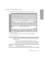
Related documents
This is one of six volumes that document HP Ultrium drives. This volume provides background
information for driver and application developers. The following documents provide additional
information:
Documents specific to HP Ultrium drives
• Hardware Integration Guide, volume 1 of the HP Ultrium Technical Reference Manual
• Software Integration Guide, volume 2 of the HP Ultrium Technical Reference Manual
• Specifications, volume 4 of the HP Ultrium Technical Reference Manual
• HP Ultrium Configuration Guide, volume 5 of the HP Ultrium Technical Reference Manual
• Background to Ultrium Drives, volume 6 of the HP Ultrium Technical Reference Manual
• HP Ultrium Technology White Paper, which describes the features and benefits of
HP Ultrium drives
Please contact your HP supplier for copies.
Documentation map
The following will help you locate information in the 6-volume Technical Reference Manual:
Drives—general
l
SCSI Drives
Connectors
Controller architecture
Front Panel LEDs
Mechanism and hardware
FC Drives
1 HW Integration: ch. 7 1 HW Integration: ch. 4
6 Background: ch. 4
1 HW Integration: ch. 6 1 HW Integration: ch. 3
6 Background: ch. 3
Specifications
4 Specs
Installation and configuration
SCSI Drives
Connectors
FC Drives
1 HW Integration: ch. 7 1 HW Integration: ch. 4
Determining the configuration
2 SW Integration: ch. 2 2 SW Integration: ch. 2
External drives (SCSI only)
1 HW Integration: ch. 5
In Libraries
n/a
1 HW Integration: ch. 1
In Servers (SCSI only)
1 HW Integration: ch. 4
n/a
In Tape Arrays (SCSI only)
1 HW Integration: ch. 3
n/a
Modes of Usage (SCSI only)
1 HW Integration: ch. 8
n/a
Related documents
7
Optimizing performance (SCSI only)
SCSI Drives
FC Drives
1 HW Integration: ch. 8
n/a
2 SW Integration: ch. 4
UNIX configuration
5 UNIX Config
Operation
External drives (SCSI only)
In Libraries
SCSI Drives
FC Drives
1 HW Integration: ch. 5
n/a
1 HW Integration: ch. 1
In Servers (SCSI only)
1 HW Integration: ch. 4
n/a
In Tape Arrays (SCSI only)
1 HW Integration: ch. 3
n/a
SCSI Drives
FC Drives
Cartridges
Cartridge Memory (LTO-CM)
Cartridges
2 SW Integration: ch. 5
6 HW Integration: ch. 5
1 HW Integration: ch. 9 1 HW Integration: ch. 5
Features
6 HW Integration: ch. 5
Managing the use of cartridges
2 SW Integration: ch. 1
Use of cartridges
2 SW Integration: ch. 3
Interface
SCSI Drives
SCSI Guide
3 SCSI
Commands
3 SCSI: ch. 4
Error codes
1 HW Integration: ch. 10 1 HW Integration: ch. 6
Implementation
Interpreting sense data
3 SCSI: ch. 1
2 SW Integration: ch. 3
Messages
3 SCSI: ch. 2
Mode pages
—see the MODE SENSE command
3 SCSI: ch. 4
Pre-execution checks
Responding to Sense Keys and ASC/Q
Sense Keys and ASC/Q
—see REQUEST SENSE command
8
FC Drives
3 SCSI: ch. 3
2 SW Integration: ch. 6
3 SCSI: ch. 4
Maintenance and troubleshooting
SCSI Drives
Cleaning
External drives (SCSI only)
In Libraries
FC Drives
2 SW Integration: ch. 5
2 SW Integration: ch. 7
1 HW Integration: ch. 5
n/a
1 HW Integration: ch. 1
In Servers (SCSI only)
1 HW Integration: ch. 4
n/a
In Tape Arrays (SCSI only)
1 HW Integration: ch. 3
n/a
Monitoring drive and tape condition
2 SW Integration: ch. 7
Software troubleshooting techniques
2 SW Integration: ch. 1
Dealing with errors
SCSI Drives
Error Codes
Handling errors
How error correction works
FC Drives
1 HW Integration: ch. 10 1 HW Integration: ch. 6
2 SW Integration: ch. 5
6 Background: ch. 4
Logs—see the LOG SENSE command
3 SCSI: ch. 4
Recovering from write and read errors
2 SW Integration: ch. 7
Software response to error correction
2 SW Integration: ch. 3
Software response to logs
2 SW Integration: ch. 3
TapeAlert log
2 SW Integration: ch. 7
Ultrium features
SCSI Drives
Adaptive Tape Speed (ATS)
FC Drives
6 Background: ch. 1
Autoload
1 HW Integration: ch. 2
Automation Control Interface (ACI)
1 HW Integration: ch. 2
6 Background: ch. 1
Cartridge Memory (LTO-CM)
1 HW Integration: ch. 2
2 SW Integration: ch. 5
6 HW Integration: ch. 5
Data Compression, how it works
Data Compression, managing
Design principles
OBDR and CD-ROM emulation
Performance optimization
6 Background: ch. 5
2 SW Integration: ch. 5
6 Background: ch. 1
6 Background: ch. 1
2 SW Integration: ch. 7
1 HW Integration: ch. 8
n/a
2 SW Integration: ch. 1
Performance, factors affecting
2 SW Integration: ch. 4
Related documents
9
SCSI Drives
FC Drives
Software design
2 SW Integration: ch. 1
Supporting Ultrium features
2 SW Integration: ch. 5
Ultrium Format
6 Background: ch. 2
General documents and standardization
• Enhanced Small Computer System Interface (SCSI-2), ANSI X3T9.2-1993 Rev. 10L,
available through ANSI
• See http://www.t10.org/t10_main.htm for ANSI SCSI-3 and other specifications
Copies of documents of other standards bodies can be obtained from:
ANSI 11 West 42nd Street
New York,
NY 10036-8002
USA
ISO CP 56
CH-1211 Geneva 20
Switzerland
ECMA 114 Rue du Rhône
CH-1204 Geneva
Switzerland
Global Engineering Documents 2805 McGaw
Irvine, CA 92714
USA
10
Tel: +41 22 849 6000
Web URL: http://www.ecma.ch
Tel: 800 854 7179 or 714 261 1455
1 Interface Implementation
HP Ultrium drives use SCSI-3 as the interface to connect to the host system.
The SCSI interface
The Small Computer System Interface (SCSI) is an industry standard, approved by the American
National Standards Institute (ANSI). You are recommended to read the ANSI standard document
in conjunction with this manual. The ANSI specification defines the interface in general while this
document describes the HP Ultrium implementation.
The SCSI implementation provides a drive with a standard set of features and functions. These
include the following:
• Synchronous data transfers
• Asynchronous data transfers
• Implementation of all mandatory and most optional commands of the Sequential Access
command set
• LVD (Low-Voltage differential) SCSI connection
• Ultra-320 wide SCSI
• Conformance to the following SCSI standards:
• SAM-2 ANSI INCITS.366:2003
• SPI-4 ANSI INCITS.362:2002
• SPC3
• SSC-2 ANSI INCITS.380:2003
Supported messages
The following messages are supported by the drives:
•
ABORT
•
BUS DEVICE RESET
•
COMMAND COMPLETE
The SCSI interface
11
Interface Implementation
This chapter gives an overview of how the interface operates.
Full details of the messages are given in Chapter 2 and of commands in Chapter 3 and
Chapter 4.
•
DISCONNECT
•
IDENTIFY
•
IGNORE WIDE RESIDUE
•
INITIATOR DETECTED ERROR
•
MESSAGE PARITY ERROR
•
MESSAGE REJECT
• NO-OP (no operation)
•
PARALLEL PROTOCOL REQUEST (PPR)
•
RESTORE POINTERS
•
SAVE DATA POINTER
•
SYNCHRONOUS DATA TRANSFER REQUEST
•
WIDE DATA TRANSFER REQUEST
For implementation details on these messages, see Chapter 2, “Messages”
Supported commands
The following commands are supported by the drives. They include all Mandatory and Extended
commands and most Optional commands.
19h
ERASE
12h
INQUIRY
1Bh
LOAD/UNLOAD
2Bh
LOCATE
4Ch
LOG SELECT
A3h (0Ch) REPORT SUPPORTED OP CODES
4Dh
LOG SENSE
A3h (0Dh) REPORT SUPPORTED TASK MNGMNT FUNCTNS
15h/55h MODE SELECT
1Ah/5Ah MODE SENSE
5Eh
PERSISTENT RESERVE IN
REQUEST SENSE
44h
REPORT DENSITY SUPPORT
A3h (05h) REPORT DEVICE IDENTIFIER
A0h
REPORT LUNS
56h/16h RESERVE UNIT
01h
REWIND
1Dh
SEND DIAGNOSTIC
0Bh
SET CAPACITY
5Fh
PERSISTENT RESERVE OUT
1Eh
PREVENT/ALLOW MEDIUM REMOVAL
08h
READ
11h
SPACE
8Ch
READ ATTRIBUTE
00h
TEST UNIT READY
05h
READ BLOCK LIMITS
13h
VERIFY
3Ch
READ BUFFER
0Ah
WRITE
8Dh
WRITE ATTRIBUTE
ABh (01h) READ MEDIA SERIAL NUMBER
A4h (06h) SET DEVICE IDENTIFIER
34h
READ POSITION
3Bh
WRITE BUFFER
1Ch
RECEIVE DIAGNOSTIC RESULTS
10h
WRITE FILEMARKS
57h/17h RELEASE UNIT
12
03h
Interface Implementation
The following additional commands are supported for CD-ROM mode:
08h
READ 6
43h
READ TOC
28h
READ 10
2Bh
SEEK
25h
READ CAPACITY
1Bh
START/STOP UNIT
For implementation details on these commands, see Chapter 3, “Commands—introduction” and
Chapter 4, “Commands”.
Design approach
The features supported by the drive are based on standards, both official and de facto. The drive is
fully compliant with the current SCSI standards: SPC3, SSC2, SAM2, and the relevant transport
protocol (e.g. SPI4 for the parallel SCSI drive). All mandatory commands and features are
supported, as well as some that are optional. In addition, some features from older standards are
still supported for backwards compatibility.
Power-on
The drive will respond to INQUIRY, TEST UNIT READY, REPORT LUNS and REQUEST SENSE commands
within 250 ms of power on. The first command received from an initiator (other than INQUIRY and
REQUEST SENSE) will result in CHECK CONDITION status, with UNIT ATTENTION sense data reported
for the power on. Once the drive has completed its self-test and set-up procedures, it will attempt
to reload any tape that is already present in the drive. It may take some time to recover the tape,
especially if it was positioned near EOM when power was cycled. During tape recovery, medium
access commands will result in a sense key of NOT READY, with additional sense of 0401h (drive
in process of becoming ready).
Reset strategy
The drive supports reset as follows:
• The current I/O process is aborted
• Any queued I/O processes from other initiators are removed
• All negotiated settings are cleared (parallel SCSI drives only)
• Mode parameters are cleared to their default values
• Any reservations are cleared (but not persistent reservations)
• Any buffered writes are flushed to tape
• The logical position becomes undefined, unless Rewind-On-Reset has been configured in
which case the drive will rewind to BOM
SCSI features
13
Interface Implementation
SCSI features
• A UNIT ATTENTION condition is set, based on the type of reset
The drive will respond to INQUIRY, TEST UNIT READY, REPORT LUNS and REQUEST SENSE within
250 ms of the reset line being released. The first command from any initiator (other than INQUIRY,
REQUEST SENSE and REPORT LUNS) will result in CHECK CONDITION status with UNIT ATTENTION
sense data for the reset. Note that all commands will receive BUSY status until the drive has
completed its internal reset.
The Reset button on the front panel and the ACI_RESET_L line on the Automation Controller
Interface are both connected to the Power-Up Reset interrupt on the processor. The effect is
equivalent to power-cycling the drive. The contents of the tape and cartridge memory may not be
consistent after the action and any data in the drive buffer will be lost.
Abort handling
If an abort condition is detected before a command phase completes, the bus is set to bus free and
the command is not executed.
If an abort condition is detected between the end of the command phase and the start of the status
phase, the bus is set to bus free and the processing below is carried out.
If an abort condition is detected during status phase, the bus is set to bus free.
If a command (other than INQUIRY for standard data or REQUEST SENSE) is received after the
abort but before the drive is ready to process the command, the behavior depends on whether
Disconnects are allowed.
• If disconnects are allowed, the drive will disconnect and wait until the abort processing has
completed before executing the command.
• If disconnects are not allowed, a BUSY response will be returned.
14
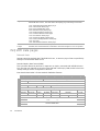
Command
Abort Processing
ERASE
Long erase is aborted as quickly as possible without corrupting the tape
format. Short erase completes.
INQUIRY
None
LOAD/UNLOAD
Load completes and logically positions the tape at BOT.
Unload is aborted leaving the logical position at BOT unless the operation
is past the “point of no return” in which case the tape is ejected.
LOCATE
The logical position is set back to that at the start of the operation.
LOG SELECT
If data transfer is complete, the command is completed, otherwise no action
is taken
LOG SENSE
None
MODE SELECT
If data transfer is complete, the command is completed, otherwise no action
is taken.
MODE SENSE
None
Interface Implementation
Abort Processing
PREVENT/ALLOW
MEDIUM REMOVAL
The command completes.
READ
The logical position is set to that at the start of the operation.
READ BLOCK LIMITS
None
READ BUFFER
None
READ POSITION
None
RECEIVE DIAGNOSTICS
RESULTS
None
RELEASE UNIT
The command completes.
REQUEST SENSE
Sense data is discarded.
RESERVE UNIT
The command completes.
REWIND
The command completes.
SEND DIAGNOSTIC
If data transfer is complete, the command is completed, otherwise no action
is taken
SPACE
The logical position is set back to that at the start of the operation.
TEST UNIT READY
None
WRITE
The logical position is set back to that at the start of the operation.
WRITE BUFFER
If data transfer is complete, the command is completed, otherwise no action
is taken.
WRITE FILEMARKS
The logical position is set back to that at the start of the operation
VERIFY
The logical position is set back to that at the start of the operation
LUN identification (parallel SCSI only)
Identify messages are used to identify the LUN being addressed by the initiator, and to identify
which LUN is reselecting the initiator. The old LUN field in the CDB from the SCSI-2 standards is
obsolete and should not be used (set to 0).
Bus parity or CRC errors
If the drive detects a bus parity error in a message out or command phase, it will still accept the
command, which will then return CHECK CONDITION. Additional sense is 4700h (SCSI parity
error). Detection of a parity error during the data out phase also causes the drive to return CHECK
CONDITION. Additional sense is set to 4701h (data phase CRC error detected) if the bus is in DT
mode or 4700h if not.
SCSI features
15
Interface Implementation
Command
If Information Units is enabled (parallel SCSI only), the drive will drop the bus on detecting a CRC
error during a LQ_IU. If the CRC error occurs during the Information Units command phase or
data out phase, the drive will return CHECK CONDITION with a CRC error. Additional sense is set to
4703h (Information Unit CRC error detected).
On detecting an Initiator Detected error, the drive will return CHECK CONDITION with additional
sense of 4800h (initator detected error message received). The exception is when Information
Units mode is enabled (parallel SCSI only), when one of the following occurs:
• If an IDE message is received during a LQ_IU, the drive drops the bus and retries the LQ_IU
pair.
• If the message is received during Status IU, the drive retries the LQ_Status pair.
• If the message is received during Data IU, the drive sends a LQ_Status with CHECK
CONDITION and additional sense of 4800h.
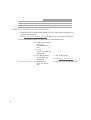
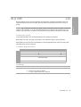
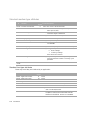
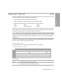
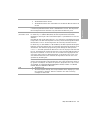
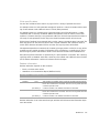
Disconnect strategy
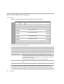
The disconnect strategy used by the drive is based on maximizing the use of the bus for large
sequential data transfers from a large data buffer. The drive will disconnect whenever it believes
that it will provide better bus use. This may be between command and data phases, between
bursts of data or before sending status. However, the drive will guarantee that it sends the
configured maximum burst size or the remaining data in the transfer in any single data phase
burst if the maximum burst size has been set to a value other than zero.
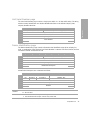
The following diagram gives an overview of the drive’s disconnect strategy:
16
Interface Implementation
CDB arrives
REQUEST SENSE from
an initiator in CA or
INQUIRY with EVPD=0
Yes
No
No
Interface Implementation
Disconnect
priv granted
Yes
Send data
Disconnect
No
No
Data transfer
required?
Yes
Execute cmd
Reselect
Reselect
Transfer data &
execute cmd
Previous cmd
still in progress?
Yes
Send status
Send status
Send BUSY
status
Cmd complete
Cmd complete
Cmd complete
Multi-initiator support
All drives are design to operate within a multi-initiator environment. The maximum number of
concurrently connected initiators is as follows:
• Parallel SCSI drives: up to 15 initiators
• Fibre Channel drives: up to 32 initiators shared across both ports
SCSI features
17
Sense Data, Unit Attention and Deferred Errors are maintained for each initiator. Mode
Parameters are common to all initiators.
The untagged queuing model implemented by the drives guarantees that all commands are
executed in strict order of receipt. Certain non-media access type commands, such as TEST UNIT
READY, INQUIRY, REQUEST SENSE and REPORT LUNS, are implicitly allowed to queue-jump other
media access type commands, such as REWIND.
The parallel SCSI drive supports the full command queuing model with a queue depth of 1
(necessary for connectivity purposes). The FC drive supports the basic queuing model with a
queue depth of 4. See “Standard Inquiry Data format (LUN0)” on page 40 for details of the BQue
and CmdQue bits which define this support.
Fibre Channel operation
NOTE:
This applies only to Fibre Channel drives.
The following sections have information specific to Fibre Channel operation:
• “Fibre Channel Logical Unit Control mode page” on page 84
• “Fibre Channel Port Control mode page” on page 85
• “Vital Product Data pages” on page 44
Fibre Channel addressing
Before describing HP’s implementation of Fibre Channel addressing, the concepts of Names and
Addresses need to be clarified.
Names
Names are 64-bit identifiers assigned permanently to the tape drive during manufacture. They are
commonly referred to as World Wide Names since they must be guaranteed unique. The names
are typically used for identifying the device to operating systems, since addresses are assigned
dynamically. There at least eight different name formats distinguished by the Network Address
Authority (NAA). Only one is used on HP Ultrium drives. This is the IEEE Registered Name
(NNA=5) and has the following format:
This name is made up of three fields:
• NAA Identifier (4 bits). “5” indicates a IEEE Registered Name.
18
Interface Implementation
• IEEE Company ID (24 bits). Assigned by IEEE to the company.
• Vendor Specified ID (36 bits). Assigned by the company.
Addresses
Each Fibre Channel port also has a Port Address which is assigned during loop initialization
and/or Fabric Login. This is a 24-bit value in the following format:
If the loop is not attached to a fabric (in other words, when it is private,) the top two bytes will be
zero. If the loop is attached to a fabric, the tape drive is assigned the top two bytes when it logs
into the fabric.
Together, the three bytes provide a unique address on the Fibre Channel fabric that is used for
frame addressing. It forms the equivalent of the Target ID or Initiator ID in SCSI.
HP’s implementation of names and addresses
The HP implementation uses three adjacent IEEE Registered Names:
• The first (last bits = 00) is used as the Port A World Wide Name.
• The second (last bits = 01) is used as the Port B World Wide Name.
• The third name (last bits = 10) is used for the Device World Wide Name.
(These are assigned during manufacture from HP’s pool of names, although only the first will
actually be stored in the drive NV-RAM).
The port addresses will be assigned using the ‘standard’ AL_PA initialization mechanisms. The
‘Fibre Channel Port Control mode page’ controls this. The drive has the ability to support hard
addresses as part of this scheme.
Fibre Channel operation
19
Interface Implementation
The AL_PA is the Arbitrated Loop Physical Address. This is normally assigned dynamically during
loop initialization.
The values of the names can be obtained using the Device Identification Vital Product Information
Page (part of the INQUIRY command).
Implications for libraries
• Normally a standalone drive will operate using its own ‘hard’ names.
• The drive knows it is in a library or other ‘managed’ environment since one of the signal
lines on the ACI (Automation Control Interface) will be tied down.
In this case, the drive will not go on the FC loop until it is told to. The library can optionally
download a new, soft base name (Port A/Device Name) into the drive at this point. The drive
will then use this as the origin of its names. The library manufacturer would be responsible for
obtaining this IEEE Registered Name. It would be a property of the library, not the drive.
• If the library wants to ‘warm swap’ drives, it can. It just ‘turns off’ the drive with the soft
name using the ACI and then turns on the spare drive, downloading the same name to it.
• If a drive is removed from the library, it will not have the ACI signal tied low and so will
revert to its original hard name. It should forget the soft name in this case.
• If the library controller breaks, the drive will time out the ACI interface in ~10 seconds. The
drive still knows it is in a library since the ACI signal is still tied low, so in this case it will
use the soft name last downloaded. This will allow drive access without confusing the host.
Field replaceable units
An FRU code identifies which part of the hardware is considered to have failed. These codes turn
up in sense data byte 14 and as the sense code qualifier for sense codes 4400h (internal target
failure) and 40XX (diagnostic failure).
20
Interface Implementation
Although there are no actual Field Replaceable Units on HP Ultrium drives, the following subassemblies can be replaced at Repair Centres:
•
Drive PCA
•
Head Assembly
•
Mechanism
•
Front Panel
CD-ROM emulation
The One Button Disaster Recovery (OBDR) functionality in HP Ultrium drives enables them to
emulate CD-ROM devices in specific circumstances (also known as being in “Disaster Recovery”
mode). The drive can then act as a boot device for PCs that support booting off CD-ROM.
Interface Implementation
A CD-ROM capable drive can be switched into CD-ROM mode by powering on with the eject
button held down. The drive then alters its behavior as follows:
• The front panel lights flash a “warbling” sequence.
• CD-ROM commands are executed (as opposed to tape drive mode when they would be
rejected). Commands specific to CD-ROM mode are READ 10, READ TOC and READ
CAPACITY. In the case of SCSI commands 08h (READ), 1Bh (LOAD/UNLOAD) and 2Bh
(LOCATE), these are interpreted as CD-ROM commands 08h (READ 6), 1Bh (START/STOP)
and 2Bh (SEEK) respectively.
• Writing is disabled.
• Normal INQUIRY data is modified to add a field indicating that the drive supports CD
emulation and to switch the peripheral device type field to indicate a CD-ROM drive.
• The mode header and mode block descriptor are modified.
• A CD-Emulation mode page is added.
• Mode data changes to reflect CD-ROM medium type and block size.
• Status reporting by the media access check is altered.
• The drive’s sense data when the media is not ready for access always indicates “loading”.
If a tape is inserted while the drive is in CD-ROM mode, the drive assumes that it will contain an
image of a CD offset 20 blocks into the tape. It reads the first 250 kilobytes of this image into
buffer space reserved for CD-caching. It then looks for a special message (“EL TORITO
SPECIFICATION”) at the 8th byte of the 18th record of the image. If the drive fails to find this
message, it ejects the tape and waits in CD-ROM mode for a properly-written CD-image tape to
be inserted.
The drive will remain in CD-emulation mode until one of the following occurs:
• A MODE SELECT command switches it back to tape drive mode using the CD-emulation
mode page.
CD-ROM emulation
21
• A SCSI bus reset occurs following the reading of at least 100 blocks of CD-ROM data by a
host.
• The user power-cycles the drive or resets it using the forced-eject mechanism.
NOTE: If the drive exits CD-ROM mode through either of the first two of these, the tape will
remain at the last logical position when in CD-ROM mode.
22
Interface Implementation
2 Messages
This chapter includes all SCSI messages, both supported and unsupported. Parts of this chapter
come from Section 5, Logical Characteristics, of the SCSI standards (see page 11).
The message system provides an initiator and a target on the SCSI bus with a means of managing
communication. The available messages are listed in this chapter.
Message Out support
Name
Code Support
Abort
06h
An abort condition is generated (see “Abort handling” on page 14).
Bus Device Reset
0Ch
A reset condition is generated (see “Reset strategy” on page 13).
Extended Message
01h
See “Extended Message Support” below.
Identify
80h+ The Identify Out message is sent by the initiator to identify the Logical
Unit to be accessed and to set Disconnect Privilege.
Initiator Detected
Error
05h
The initiator has detected an error in the data being sent in a Command,
Data or Status phase. The drive will send a restore data pointers
message to retry the data transfer. (See “Message In support” below for
details).
If the message is received immediately after an Identify message or after
the Command Complete message has been sent, the drive will go Bus
Free.
09h
The initiator has detected a parity error in a message. The drive will retry
the message. (See “Message In support” below for details).
If the message is received immediately after an Identify message or after
the Command Complete message has been sent, the drive will go Bus
Free.
Message Reject
07h
This message is sent when the initiator does not support a message sent
by the drive or that the message is inappropriate. If the message being
rejected is Disconnect, Synchronous Data Transfer Request or Wide Data
Transfer Request, the operation continues without those features. For all
other messages, the message is treated as an Abort message.
If the message is received during a Command, Data or Status phase,
immediately after an Identify message or after the Command Complete
message has been sent, the drive will go Bus Free.
No Operation
08h
This message has no effect and is ignored.
23
Messages
Message Parity Error
Message In support
Name
Code
Support
Command Complete
00h
This message is sent by the drive at the end of the status phase to
indicate that a command is complete. Once the message is sent, the
drive releases the bus and goes to Bus Free.
Disconnect
04h
This message is sent by the drive to indicate that it is about to
disconnect from the bus and go to Bus Free. During a Data phase, it is
always pre-ceded by a Save Data Pointers message. If a Message
Reject message is received in response to this message, then the
disconnect is prevented.
Extended Message
01h
See “Extended Message Support” below.
Identify
8Xh
The Identify In message is sent to the initiator during reconnect to
indicate which Logical Unit is reconnecting.
Ignore Wide Residue
23h
This message is sent by the drive to the host to indicate that a byte on
a wide bus is not valid.
This is supported whenever a wide transfer is active. It should be sent
at the end of the data phase. The standard action of the drive is to
send this message between the data phase and the status phase with
no disconnect.
24
Message Reject
07h
This message is sent to the initiator when the message received by the
drive is unsupported or inappropriate.
Restore Pointers
03h
This message causes the initiator to reset its data transfer pointers to
the values they held when the last save data pointers message was
sent. It will be sent when a parity error is detected on the bus or when
an Initiator Detected Error message is received in order to retry the
data phase.
Save Data Pointers
02h
This message instructs the initiator to save its current data transfer
pointers for use with a subsequent Restore pointers message. This
message will always be sent before a Disconnect message during
data phases.
Messages
Extended Message support
Name
Code
Support
Synchronous Data
Transfer Request
01h
The drive can initiate a Synchronous data transfer negotiation. If the
message is received after selection and before the command phase, it
will then go to message-in phase and respond with a valid response to
complete the negotiation.
Wide Data Transfer
03h
The drive can initiate a Wide data transfer negotiation. If the message
is received after selection and before the command phase, it will then
go to message-in phase and respond with a valid response to complete
the negotiation.
Note that SDTR negotiated parameters will become asynchronous after
a WDTR.
Parallel Protocol
Request
04h
The drive will never initiate a Parallel Protocol Request transfer
negotiation but will expect the initiator to do so.
If the message is received after selection and before the command
phase, it will then go to message-in phase and respond with a valid
response to complete the negotiation.
Synchronous Data Transfer Request
7
6
5
4
3
0
Extended Message (01h)
1
Extended Message Length (03h)
2
SDTR (01h)
3
Transfer Period Factor
4
Req/Ack Offset
2
1
0
2
1
0
7
6
5
4
3
0
Extended Message (01h)
1
Extended Message Length (02h)
2
WDTR (01h)
3
Transfer Width Exponent
Messages
Wide Data Transfer Request
25
Parallel Protocol Request
7
6
5
4
3
0
Extended Message (01h)
1
Extended Message Length (06h)
2
Parallel Protocol Request (04h)
3
Transfer Period Factor
4
Reserved (0)
5
Req/Ack Offset
1
0
Transfer Width Exponent
6
7
2
PComp_En
RTI
Rd_Strm WR_Flow Hold_MCS QAS_Req DT_Req IU_Req
Fields:
Transfer Period
Factor
08h Transfer period of 6.25 ns, Paced Information Unit transfers
09h Transfer period of 12.5 ns (FAST-80). Only valid when DT transfers have
been requested
0Ch Transfer period of 50 ns (FAST-20) — LVD/SE drives only
19h Transfer period of 100 ns (FAST-10)
32h Transfer period of 200 ns (FAST-5)
Req/Ack Offset
This has a maximum value of 255.
Transfer Width
Exponent
For ST transfers, this can be either 0 (Narrow) or 1 (Wide).
PComp_En
Precompensation enable bit. Supported.
RTI
Retain Training Information bit. Supported.
For DT transfers, it must be set to 1.
Rd_Strm
0
Read streaming and read flow control enable bit. Not supported, so the
drive will always return zero.
Wr_Flow
0
Write flow control enable bit. Not supported; the drive will always return
zero.
Hold_MCS
0
Hold Margin Control Settings bit. Not supported; the drive will always return
zero.
QAS_Req
0
QAS enable request bit. Not supported; the drive will always return zero.
DT_Req
This bit determines whether DT mode has been requested, in other words,
packetized data transfers. Supported.
IU-Req
Information units enabled request bit. Supported.
Status
A Status byte is sent from the drive to the host during the Status phase at the end of each
command as specified in the SCSI specification, unless the command has been cleared by an
ABORT message, by a BUS DEVICE RESET message, or by a hard reset.
26
Messages
The Status bytes that the drive returns are as follows:
GOOD: This status indicates that the drive has successfully completed the command.
02h
CHECK CONDITION: Any error, exception, or abnormal condition that causes sense data to be
set returns CHECK CONDITION. The REQUEST SENSE command should be sent following
this status to determine the nature of the error.
04h
CONDITION MET: This status will never be returned by an HP Ultrium tape drive.
08h
BUSY: The drive is unable to execute the command at this time. Try again later. The drive tries
to avoid using this status code during normal operation. It can sometimes be used after
commands have been aborted, during power-on and if there are multiple selecting initiators.
10h
INTERMEDIATE: This status will never be returned by an HP Ultrium tape drive.
14h
INTERMEDIATE CND: This status will never be returned by an HP Ultrium tape drive.
18h
RESERVATION CONFLICT: Returned if the drive is reserved by another party. See the
Reservation check.
22h
COMAND TERMINATED: This status will never be returned by an HP Ultrium tape drive.
28h
QUEUE FULL
Messages
00h
Status
27
28
Messages
3 Commands—introduction
This chapter contains notes relating to the SCSI commands listed in Chapter .
Summary
The following table is a summary of the SCSI commands for sequential access devices, showing
the operation code:
Command Name
Opcode
00h
01h
03h
05h
08h
08h
0Ah
0Bh
10h
11h
12h
13h
15h
16h
17h
19h
1Ah
1Bh
1Bh
1Ch
1Dh
1Eh
25h
28h
TEST UNIT READY
REWIND
REQUEST SENSE
READ BLOCK LIMITS
READ
READ 6 (CD-ROM)
WRITE
SET CAPACITY
WRITE FILEMARKS
SPACE
INQUIRY
VERIFY
MODE SELECT
RESERVE UNIT
RELEASE UNIT
ERASE
MODE SENSE
LOAD/UNLOAD
START/STOP UNIT (CD-ROM)
RECEIVE DIAG RESULTS
SEND DIAGNOSTIC
PREVENT MEDIUM REMOVAL
READ CAPACITY (CD-ROM)
READ 10 (CD-ROM)
2Bh
2Bh
34h
3Bh
3Ch
43h
44h
4Ch
4Dh
55h
56h
57h
5Ah
5Eh
5Fh
8Ch
8Dh
A0h
A3h (05h)
A3h (0Ch)
A3h (0Dh)
A4h (06h)
ABh (01h)
Command Name
LOCATE
SEEK (CD-ROM)
READ POSITION
WRITE BUFFER
READ BUFFER
READ TOC (CD-ROM)
REPORT DENSITY SUPPORT
LOG SELECT
LOG SENSE
MODE SELECT (10)
RESERVE UNIT (10)
RELEASE UNIT (10)
MODE SENSE (10)
PERSISTENT RESERVE IN
PERSISTENT RESERVE OUT
READ ATTRIBUTE
WRITE ATTRIBUTE
REPORT LUNS
REPORT DEVICE IDENTIFIER
REPORT SUPPORTED OPCODES
REPORT SUPPORTED TASK MGMNT FNS
SET DEVICE ID
READ MEDIA SERIAL NUMBER
Command details
The command descriptions in Chapter 4 are listed in alphabetical order of command name. Each
command is described briefly. This is followed by a list of pre-execution checks which are
described below. The Command Descriptor Block (CDB) is then given, with details of the various
parameter bits and fields.
Summary
29
Commands—introduction
Opcode
Pre-execution checks
NOTE:
In compliance with the SCSI specification, the drive terminates a command with a
CHECK CONDITION status and sets the sense key to ILLEGAL REQUEST when a reserved bit, byte,
field or code is received which is not zero.
Before executing a command, the drive makes a number of checks. They fall into three categories:
• Checks on the command sent by the host. These ensure that no reserved or fixed fields have
been set to illegal values. They check the syntax of commands, in other words the cross
dependency of fields. For example, the Flag bit must not be set if the Link bit is not set.
• Checks to ensure that there are no outstanding UNIT ATTENTION or DEFERRED ERROR events
posted for the host that has sent the command.
• Checks on media access abilities. These are performed for commands requiring access to
the cartridge. A command is rejected if it attempts to access the cartridge when no
cartridge is present or the cartridge is unloaded.
The checks are described below in alphabetical order. The usual order of execution is Illegal Field,
Fixed Bit, Flag Link, Bad LUN, Reservation, Deferred Error, Unit Attention, Media Access, Media
Write, Diagnostic Status, Humidity, Parameter List.
Bad LUN check
For all commands except INQUIRY 12h, this checks that the LUN specified by the host is zero. The
LUN is taken from the lowest 5 bits of the host’s IDENTIFY message.
• If no IDENTIFY message is supplied, the LUN is taken from the host’s Command Descriptor
Block.
• If an IDENTIFY message is supplied, the LUN in the host’s Command Descriptor Block is
ignored
• If the LUN is unsupported, and the host command is not REQUEST SENSE, CHECK
CONDITION is reported to the host with a sense key of ILLEGAL REQUEST, and additional
sense of 2500h (logical unit not supported).
• If the LUN is unsupported, and the host command is REQUEST SENSE, the original sense
data is replaced with a sense key of ILLEGAL REQUEST, and additional sense of 2500h
(logical unit not supported). This new sense data is returned to the host. Once the
command has completed successfully, the sense data is cleared.
Deferred Error check
A deferred error is generated when a command with immediate report fails after the report has
been returned. The check looks to see if a deferred error exists for the host which sent the
command, in other words, a deferred error for which CHECK CONDITION status has not yet been
30
Commands—introduction
reported. If such an error exists, then the drive reports CHECK CONDITION. The sense data for the
command is set to DEFERRED ERROR (which was generated when some previous command failed).
Note that if a UNIT ATTENTION condition and a DEFERRED ERROR condition both exist for an
initiator, the DEFERRED ERROR condition will be reported first. This is because the operation leading
to the deferred error must have been older than that leading to the unit attention. The drive reports
the conditions in the order in which they arose.
Diagnostic Status check
This ensures that the drive is in a fit state to access the media. It does this by checking that there is
no DIAGNOSTIC FAIL status within the drive.
If the drive has failed diagnostics, CHECK CONDITION is reported with a sense key of HARDWARE
ERROR and additional sense of 400Xh (diagnostic failure on component X).
Fixed Bit check
For the READ, VERIFY and WRITE commands, a Fixed bit set to 1 indicates that the length parameter
of the command is for fixed block mode. If fixed block mode is selected then the block size in the
Mode Select block descriptor must not be zero. Otherwise CHECK CONDITION is reported and the
sense data is set as described for the ILLEGAL FIELD check.
Flag Link check
This check ensures that the host has not set the Flag bit in the control byte of the command without
setting the Link bit as well. If the test fails then CHECK CONDITION is reported with a sense key of
ILLEGAL REQUEST and additional sense of 2400h (invalid field in CDB). The Flag field is identified
as the bad field.
Illegal Command check
If the drive does not recognize the opcode of the command that it has been sent, it will do one of
the following:
• Report an invalid field in the command descriptor block. The sense key will be set to ILLEGAL
REQUEST, the additional sense code will be set to 2400h (invalid field in CDB) and the field
pointer in the sense data will be zero.
Illegal Field/Request check
Checks are performed to ensure the host has not set any of the following in the command
descriptor block:
• a fixed field
Pre-execution checks
31
Commands—introduction
• Report CHECK CONDITION status. The sense key will be set to ILLEGAL REQUEST and the
additional sense code will be set to 2000h (invalid command opcode).
• a reserved field
• the control field
• two or more fields to logically conflicting values
If a field has been set to an illegal value:
• CHECK CONDITION status is reported to the host with a sense key of ILLEGAL REQUEST and
additional sense of 2400h “invalid field in CDB”.
• The sense key specific bit is set and the sense key specific bytes will be a field pointer.
• The command/data bit is set, indicating that the illegal parameter was in the command.
NOTE: Command descriptor blocks are scanned from left (bit 7) to right (bit 0), and down
(from byte 0 to byte n). The field pointer will be set to point to the first bit of the first illegal field
encountered using this scanning route. In some cases, where multiple fixed fields are
contiguous, the field pointer might be set to point to the first bit of the first fixed field in the
group of fixed fields, whereas the actual illegality may lie in a later bit.
Media Access check
This checks if the drive is able to perform media access commands. If the media is inaccessible
then CHECK CONDITION status is reported with a sense key of NOT READY. The additional sense
will be set to one of the codes associated with the NOT READY key.
32
Commands—introduction
Media Information check
During power-on and following a SCSI reset, knowledge of the whereabouts of the cartridge is
unavailable. It is not possible to execute commands which assume that this knowledge is available
until the drive has recovered from the power-on or reset.
The test checks whether the drive knows if a cartridge is physically present in the drive.
If information about the tape cartridge is not available, the test fails with CHECK CONDITION, a
sense key of NOT READY, and additional sense of 3E00 (logical unit has not self-configured yet).
Commands—introduction
Media Write check
This checks whether the media is write-protected. If it is, CHECK CONDITION is reported with a
sense key of DATA PROTECT and additional sense of 2700h (write-protected).
Pre-execution checks
33
Parameter List check
For LOG SELECT, MODE SELECT and some diagnostic commands, the associated data sent to the
drive is in the form of parameter lists. These are described under the command names in the next
chapter. Checks are performed to test the following:
• Fixed and reserved fields have not been modified. Fixed fields are indicated by a number
in round brackets following the field name.
• A field has been set to an invalid value.
• The syntax of the page of parameters has been violated—for example, where a particular
value in one field imposes limitations on the valid range for another field.
If a field has been set to an illegal value, CHECK CONDITION is reported to the host with a sense
key of ILLEGAL REQUEST and additional sense of 2600h (invalid field in parameter list).
The drive scans the data in the Command Description Block from “left” (bit 7) to “right”, and
“down” (from byte 0 to byte n). It sets the field pointers to the first bit of the first bad field
encountered. If the bad field is contained in a contiguous group of fixed fields, the pointers
indicate the first bit of the first field in the group, even though the error may be in a later field in the
group.
NOTE: With MODE SELECT, the drive checks the integrity of the whole parameter list before acting on
any parameters, so all the mode parameters need to be correct before any of them are implemented.
Reservation check
This checks to see if the drive has been reserved for use by a host, and if it has, whether the host is
the same host that sent the command being executed.
If the drive has been reserved for some other host then RESERVATION CONFLICT status is reported.
See the RESERVE UNIT (page 164) and RELEASE UNIT (page 135) commands.
Unit Attention check
This checks if a UNIT ATTENTION condition exists for the host which sent the command. If it does,
the drive reports CHECK CONDITION status with a sense key of UNIT ATTENTION. The remaining
sense data will be set according to the unit attention condition which exists. See Unit Attention
Sense in the description of the REQUEST SENSE command on page 155.
34
Commands—introduction
Command descriptor block
A SCSI command descriptor block (CDB) is a sequence of 6, 10, 12 or 16 bytes sent by a host to
a SCSI target with the bus in command phase. The CDB tells the drive what action should be
performed. The final byte is known as the Control byte.
7
6
5
3
Group Code
0
2
1
Operation Code
(MSB)
Multi-Byte Parameter
n−1
n
0
Reserved (0)
1
2
4
(LSB)
Vendor Unique (0)
Reserved (0)
NACA(0) Flag (0) Link (0)
There are a number of fields in a CDB which are common to all commands. These are shown in
the following table.
Group Code and The operation code uniquely identifies the command. The top three bits of the
Operation Code operation code are known as the group code and these define the length of the
command descriptor block:
Group
Group
Group
Group
Group
Group
Group
Group
0
1
2
3
4
5
6
7
Six-byte commands
Ten-byte commands
Ten-byte commands
Six-byte commands
Sixteen-byte commands
Twelve-byte commands
not supported
not supported
A reserved field should always be set to zero. The drive checks reserved fields, and if
one is non-zero then it will reject the command with CHECK CONDITION.
Multi-Byte
Parameter
A multi-byte parameter field in a command is “big-endian”, that is, bit 7 of the first
byte of this field is the most significant.
Control
The control field is mainly concerned with the use of linked commands. These are not
supported by the LTO SCSI Command Set, so a CHECK CONDITION will be generated
if this field is set to anything other than zero.
Vendor-Unique
This field is ignored by the firmware
NACA
0 The Normal ACA flag is 0, indicating that it is not supported.
Flag
0
Link
0 Linked commands are not supported.
Command descriptor block
Commands—introduction
Reserved
35
36
Commands—introduction
This chapter describes all SCSI commands. Parts of the chapter are based on sections of the SCSI
specification (see page 11).
For general notes on the command descriptions, see Chapter 3.
37
Commands
4 Commands
ERASE
19h
The ERASE command is used to erase data on tape from the current logical position. The Long bit
is used to decide whether the ‘old’ data is physically overwritten or not. ERASE commands (short or
long) to a drive containing a WORM cartridge will not overwrite or erase user data on tape.
Pre-execution checks:
Illegal Field
Reservation
Deferred Error
Unit Attention
Media Access
Media Write
Diagnostic Status
Command descriptor block:
7
6
5
4
3
2
1
0
Immed
Long
Operation Code (19h)
0
Reserved (0)
1
2–4
Reserved (0)
5
Control
CDB fields:
Immed
0 The drive reports status after the command has completed.
1 The drive reports status when it starts the command (after any pre-execution checks and
prerequisite unloads have completed).
Long
The Long bit controls the distance to be erased.
0 The current position becomes the end of logical data.
1 End of Data is written, followed by Data Set Separators to the end of the tape.
NOTE: Short erase is only used to truncate data at the current logical position. It cannot be
used to create a “hole” in the tape into which data can subsequently be written “in place”. This
will merely cause the drive to streamfail. The logical tape position is unaffected by this
command. A CHECK CONDITION for Early Warning EOM (drive error code 2C98h) will only be
given if the tape is logically positioned past EOT immediately before the erase.
Erase Specific status:
Event
38
Status
Key
Additional Sense
The erase fails
CHECK CONDITION HARDWARE ERROR 5100h (erase failure)
WORM media: Erase would
result in user data being overwritten.
CHECK CONDITION DATA PROTECT
Commands
300Ch (WORM medium
—overwrite attempted)
INQUIRY
12h
NOTE: This command is immune from most of the pre-execution checks that other commands
must pass (for example, it can be executed while the unit is reserved for another host). Unit
attention and deferred error conditions are preserved and reported on subsequent commands.
Pre-execution checks:
Only the Illegal Field Check is performed before the command is executed.
If the EVPD bit is clear, the page code must be zero, otherwise illegal request is reported.
If the EVPD bit is set, the page code must be one of the supported page codes for Inquiry data.
Otherwise illegal request is reported.
Command descriptor block:
7
6
5
4
3
2
1
0
Operation Code (12h)
0
LUN
1
Reserved (0)
EVPD
Page Code
2
3
Allocation Length
4
Control
5
CDB fields:
LUN
This field is ignored.
EVPD
Enable Vital Product Data
0
1
Normal inquiry data is returned.
A page of vital product data is returned.
INQUIRY 12h
39
Commands
INQUIRY tells the drive to return information about the basic operating parameters to the host.
These parameters cannot be changed. The drive returns Inquiry data to the host in a data-in
phase.
If the EVPD bit is zero the Page Code field must be zero.
If the EVPD bit is set to 1, the drive returns the Inquiry page in this Page Code field:
Page Code
00h
80h
83h
86h
C0h
C1h
C2h
C3h
C4h
C5h
C6h
Supported Vital Product Pages page
Unit Serial Number page
Device Identification page
Extended Inquiry Data page
Firmware Revision Levels page
Hardware Revision Levels page
PCA Revision Levels page
Mechanism Revision Levels page
Head Assembly Revision Levels page
ACI page
ARM Firmware Revision Levels page
The maximum amount of data (in bytes) that should be returned. If more than this is
available, the amount returned is truncated to allocation length. No error is reported.
Allocation
Length
INQUIRY data pages
Returned data:
INQUIRY returns its standard data if the EVPD bit is zero, or returns a page of data as specified by
the Page Code field when EVPD is one.
Standard Inquiry Data format (LUN0)
This is the data returned by the drive in response to an Inquiry command with its EVPD bit set to
zero. The data also depends on the value of the LUN field in the Inquiry CDB, the LUN value in the
identify message and the configuration of the drive.
Note that the data below is for the standard distribution firmware.
7
5
2
1
0
Reserved (0)
Version Number (5)
Obsolete
Obsolete
NACA(0)
HiSup(0)
Response Data Format (2)
Additional Length (5Bh)
4
5
SCCS (0)
ACC (0)
6
BQue(0)
EncSvr(0)
7
8
Obsolete
(MSB)
15
16
31
40
3
Peripheral Device Type (01h)
RMB (1)
2
3
4
Peripheral Qualifier (000b)
0
1
6
Commands
(MSB)
3PC (0)
Reserved (0)
Protect(0)
VS(0)
TPGS (01b)
MultiP(0)
MChngr(0)
Obsolete
Adr16
WBus16
Sync
Linked(0)
Vendor Identification
(“HP
“)
Product Identification
Obsolete
CmdQue(1)
VS(0)
(LSB)
(LSB)
7
5
(MSB)
36
2
1
0
(LSB)
Reserved (0)
39
WORM Version
40
41
WORM
Reserved (0)
42
(MSB)
OBDR string (“$DR-10”) or Reserved (0) if not supported
48
49
(LSB)
Reserved (0)
55
Reserved (0)
56
Clocking
QAS (0)
IUS
Reserved (0)
57
58
3
Product Revision Level
35
43
4
(MSB)
Version Descriptor 1
59
(LSB)
-------72
(MSB)
Version Descriptor 8
73
74
(MSB)
(LSB)
Reserved (0)
95
(LSB)
The Standard Inquiry Data is based on the SCSI 3 standard for Standard Inquiry Data.
For the LUN to which the drive is attached, the Peripheral Qualifier field is set to 000b, the
Peripheral Device Type field is set to 01h, the Removable Medium (RMB) flag is set to 1 and the
Device-type modifier is set to 0.
Inquiry Data fields
Peripheral Qualifier
Peripheral Device Type
000b There is a device on the logical unit selected, so the LUN field in the
identify message was 0.
011b The LUN field in the identify message has specified an unsupported
logical unit. This means any LUN other than 0.
01h Sequential Access Device
05h CD Device (reported when in OBDR mode)
1Fh No Device (the Peripheral Qualifier will be 011b in this case)
RMB
1
The Removable Medium bit is one, indicating that the tape can be
removed.
Device-Type Modifier
0
This is a six-bit user defined code, set to zero.
Version Number
5
The drive complies with the SPC-3 standard.
INQUIRY 12h
41
Commands
32
6
NACA
0
The Normal ACA flag is 0, indicating that it is not supported.
HiSup
0
The Hierarchical Support flag is 0, indicating that the hierarchical
addressing model is not supported.
Response Data Format
2
The Inquiry Data format complies with the SCSI-3 standard.
Additional Length
SCCS
ACC
TPGS
The length in bytes of the length of the rest of the Inquiry data.
0
No storage array controller component is embedded in the drive.
0
No Access Controls Coordinator may be addressed through this LUN.
01b Target Port Group Support. Only implicit asymmetric logical unit access is
supported.
3PC
0
Third-Party Copy commands are not supported.
Protect
0
Protection information is not supported.
BQue
Basic Queuing flag
0
The flag is zero for SCSI drives, with CmdQue = 1.
1
The flag is 1 for Fibre Channel drives, with CmdQue = 0.
EncSvr
0
The drive does not support Enclosure Services command.
VS
0
Vendor-Specific field—not currently used
MultiP
1
The drives has multiple ports.
MChngr
0
The drive is not embedded within or attached to a medium transport
element.
Adr16
1
16-Bit Addresses are supported. The flag is only valid for parallel SCSI.
WBus16
1
Wide Bus 16 is supported. The flag is only valid for parallel SCSI.
1
Synchronous data transfer is supported. The flag is only valid for parallel
SCSI.
Linked
0
The drive does not support linked commands.
CmdQue
0
For FC drives, with BQue = 1.
1
For SCSI drives, with BQue = 0.
Sync
Vendor
Identification
A vendor-specific, 8-byte string of ASCII characters, left justified and padded
with space characters “HP”.
Product Identification
A left-justified, vendor-specific, 16-byte string field of ASCII characters with
space character padding on the right. The string consists of two parts:
• First half (bytes 16–23): “Ultrium”
• Second half (bytes 24–31): “<generation>-<interface type>”
The following strings have been defined:
Gen 1 SCSI drive: “Ultrium 1-SCSI”
All Gen 2 drives: “Ultrium 2-SCSI”
All Gen 3 drives: “Ultrium 3-SCSI”
42
Commands
Product Revision Level A vendor-specific string of four ASCII characters: “CNNV”:
C is the codename (G for a Gen 3 SCSI drive, L for Gen 3 FC drive)
NN are two digits that indicate the build of the variant.
V is an ASCII character representing the OEM variant of the code. “D” is the
standard distribution variant.
•
•
•
WORM
OBDR string
Clocking
QAS
IUS
Version Descriptor
The version of WORM supported.
1
The drive supports the LTO WORM specification.
Commands
WORM Version
“$DR-10” if the drive supports Tape Disaster Recovery.
0
For FC drives.
3
For SCSI drives, indicating that the drive supports both ST and DT
transfers.
0
The drive does not support Quick Arbitration and Selection.
Information Units
0
Not supported for all drives other than SCSI.
1
Supported for SCSI drives.
These fields can be used to identify up to eight standards to which the drive
conforms. The values supported are listed below.
For SCSI drives, it is recommended that the first version descriptor is used for the
SCSI architecture standard, followed by the physical standard, if any, followed
by the SCSI protocol, followed by the appropriate SPC version, followed by the
device type command set, followed by the secondary command set, if any.
The following are the SCSI version descriptors:
Value
1
2
3
4
5–8
005Ch
0B56h
0300h
037Dh
0000h
Standard
SAM2 ANSI INCITS.366.2003
SPI4 ANSI INCITS.362:2002
SPC3
SSC2 ANSI INCITS
not used
The following are the FC version descriptors:
Value
1
2
3
4
5
6
7
8
0054h
0917h
0D7Ch
0DA0h
131Bh
1320h
0277h
021Ch
Standard
SAM-2 T10/1157-D rev 23
FCP-2 ANSI NCITS.332:1999
FC-AL-2 ANSI NCITS.350:200x
FC-FS (no version claimed)
FC-Tape T11/1315 revision 1.17
FC-FLA (no version claimed)
SPC-2 ANSI NCITS.351:2001
SSC ANSI NCITS.335:2000
Vendor Specific data may be sent after the Product Revision Level.
INQUIRY 12h
43
Vital Product Data pages
The following tables describe the vital product data pages. These pages are returned by the
INQUIRY command when the EVPD bit is set and the appropriate Page Code is set in the
Command Descriptor Block. They contain vendor-specific product information.
Supported Vital Product Data Pages page
This is the data returned by the drive in response to an Inquiry command with its EVPD bit set to
one and its Page Code field set to 0.
This page contains a list of all the VPD page-codes supported by the drive.
7
0
44
6
5
Peripheral Qualifier (0)
4
3
2
1
Page Code (00h)
2
Reserved (0)
3
Page Length (XXh)
4
Supported Pages Code (00h)
5
Unit Serial Number page (80h)
6
Device Identification page(83h)
7
Extended Inquiry Data page (86h)
8
Sequential Device Access Capabilities page (B0h)
9
Firmware Revision Levels page (C0h)
10
Hardware Revision Levels page (C1h)
11
PCA Revision Levels page (C2h)
12
Mechanism Revision Levels page (C3h)
13
Head Assembly Revision Levels page (C4h)
14
Auto-Changer Interface Revision Levels page (C5h)
15
ARM Firmware Revision Levels page (C6h)
Commands
1
Peripheral Device Type (1)
0
Unit Serial Number page
The Unit Serial Number page contains a single value which is a 10-byte ASCII string. The string,
with the Vendor Identification and Product Identification fields in the standard Inquiry data,
uniquely identifies the drive.
6
5
4
3
Peripheral Qualifier (0)
1
Page Code (80h)
2
Reserved (0)
1
0
Page Length (0Ah)
3
4
2
Peripheral Device Type (1)
Commands
7
0
(MSB)
Serial Number
13
(LSB)
Device Identification page
The Device Identification page contains information that identifies the tape drive uniquely. For
SCSI, a combination of the Vendor ID and Serial Number is returned. For Fibre Channel, the Port
and Device Names are returned as well
7
0
6
5
4
3
Peripheral Qualifier (0)
1
0
Peripheral Device Type (1)
1
Page Code (83h)
2
Reserved (0)
3
Page Length (n−3)
4
2
(MSB)
Identification Descriptors
n
(LSB)
Identification Descriptors are constructed as follows:
7
1
6
PIV
Rsvd (0)
4
3
2
1
0
Code Set
Association
Identifier Type
Reserved (0)
2
Identifier Length (n−3)
3
4
5
Protocol Identifier
0
(MSB)
n
Identifier
Protocol
Identifier
0h Fibre Channel
Code Set
1 The Identification Descriptor is a binary field.
(LSB)
1h Parallel SCSI
2 The Identification Descriptor contains only ASCII data.
INQUIRY 12h
45
PIV
1 The Protocol Identifier field is valid. This is set for an Association value of 1.
Association
0 The Identifier field is associated with the addressed logical unit.
1 The Identifier field is associated with the port that received the request.
2 The Identifier field is associated with the SCSI target device that contains the addressed
logical unit.
3 Reserved
Identifier Type
1 Vendor ID followed by the product identification field from the standard inquiry data and
the serial number field from the Serial Number Inquiry page.
3 All devices with a Fibre Channel interface support an Identifier type 3. In this case the
Identification Descriptor is the Fibre Channel 64-bit Name Identifier.
Defined identifiers
The following identifiers will be returned in the given order. What Port Name is returned depends
on which port the Inquiry is sent to.
Logical Unit Identifier
7
5
4
3
Protocol Identifier (0)
0
1
6
PIV (0)
Rsvd (0)
3
Identifier Length (8)
SSC Device Logical Unit Name (IEEE Registered Name)
11
0
Identifier Type (3)
Reserved (0)
(MSB)
1
Code Set (1)
Association (0)
2
4
2
(LSB)
Port Name (FC only)
7
4
3
PIV (1)
Rsvd (0)
Association (1)
Reserved (0)
3
Identifier Length (8)
11
Commands
(MSB)
2
1
0
Code Set (1)
2
4
46
5
Protocol Identifier (0)
0
1
6
Port Name
(IEEE Registered Name)
Identifier Type (3)
(LSB)
Port Identifier (FC only)
5
4
3
Protocol Identifier (0)
0
1
6
PIV (1)
Rsvd (0)
Association (1)
3
Identifier Length (4)
Port Identifier
7
0
Identifier Type (4)
Reserved (0)
(MSB)
1
Code Set (1)
2
4
2
(LSB)
The Port Identifier will be set to 1 if the addressed port is port A, and set to 2 if the addressed port
is Port B.
Target Name
7
5
4
3
Protocol Identifier
0
1
6
PIV (1)
Rsvd (0)
Association (2)
Reserved (0)
Identifier Length (8)
Device Name
(IEEE Registered Name)
11
0
Identifier Type (3)
3
(MSB)
1
Code Set (1)
2
4
2
(LSB)
Target Name
7
6
PIV (1)
Rsvd (0)
4
3
Protocol Identifier
0
1
5
Reserved (0)
3
Identifier Length (34)
4
(MSB)
12
(MSB)
27
28
37
(MSB)
1
0
Code Set (2)
Association (2)
2
11
2
Vendor ID
Product Identification
Serial Number
Identifier Type (1)
(LSB)
(LSB)
(LSB)
INQUIRY 12h
47
Commands
7
Extended INQUIRY Data VPD page
This page provides an application client with a means of obtaining information about the drive.
7
0
6
5
4
3
Peripheral Qualifier (0)
2
1
0
Peripheral Device Type (1)
1
Page Code (86h)
2
Reserved (0)
Page Length (3Ch)
3
Reserved (0)
4
RTO (0)
Reserved (0)
5
GRD_CHK(0) APP_CHK(0) REF_CHK(0)
HEADSUP(0) ORDSUP(0)
SIMSUP(1)
NV_SUP(0)
V_SUP (0)
6
7
Reserved (0)
63
1
SIMSUP
The drive supports the Simple Task attribute.
Sequential Access Device Capabilities page
This page provides the application client with a means of determining which features are
supported by the Device Server.
7
0
6
5
4
Peripheral Qualifier (0)
3
2
1
0
Peripheral Device Type (1)
1
Page Code (B0h)
2
Reserved (0)
3
Page Length (4h)
Reserved (0)
WORM
Reserved (0)
WORM
48
Commands
1
The Device Server supports Write Once Read Many (WORM) operation.
Drive Component Revision Levels pages
6
5
4
Peripheral Qualifier (0)
0
3
Page Code
2
Reserved (0)
3
Page Length (5Ch)
(MSB)
Component (“CCCCCCCCCCCC”)
29
30
(MSB)
Version (“RRR.VVV”)
48
49
(MSB)
Date (“YYYY/MM/DD hh:mm”)
72
73
1
0
Peripheral Device Type (1)
1
4
2
(MSB)
Variant (“XXXXXXXXXXXX”)
95
Commands
7
(LSB)
(LSB)
(LSB)
(LSB)
The Drive Component Revision Levels pages contain details of the revisions of each of the major
sub assemblies of the drive. For any given product, if these pages are the same then the drive has
been built with the same components and with the same manufacturing process.
Each entry is a null-terminated ASCII string.
Page Code
Page Code
C0h
C1h
C2h
C3h
C4h
C5h
C6h
-
Firmware
Hardware
PCA
Mechanism
Head Assembly
ACI
ARM
Component Name
“Firmware”
“Hardware”
“PCA”
“Mechanism”
“Head Assy”
“ACI”
“IO Firmware”
Component A 12-character entry to identify the component that the revision is for.
Version
A 7-character version code with a three-digit major revision number, a period and a threedigit minor version number.
Date
The date of the version.
Variant
An identifier indicating what version of the product this is.
INQUIRY 12h
49
LOAD/UNLOAD
1Bh
The LOAD/UNLOAD command allows the host to specify that a tape cartridge present in the drive
is either made ready for data transfer (“loaded”) or disabled for data transfer (if Prevent Media
Removal is set). It can also cause the cartridge to be ejected from the drive (“unloaded”).
Pre-execution checks:
Illegal Field
Reservation
Deferred Error
Unit Attention
Diagnostic Status
Media Information
If an unload is to be performed, the drive checks if the tape is currently being loaded. If it is,
CHECK CONDITION is reported with a sense key of NOT READY and additional sense of 0401h
(becoming ready).
If a load is to be performed, the drive checks to ensure that a tape cartridge is present. If not, it
reports CHECK CONDITION with a sense key of NOT READY and additional sense of 3A00h
(medium not present). If the media is currently being unloaded or ejected, it reports CHECK
CONDITION with sense key of NOT READY and additional sense of 0400h (cause not reportable).
Command descriptor block:
7
6
5
4
3
0
Operation Code (1Bh)
1
Reserved (0)
2
1
0
Immed
Reserved (0)
2
Reserved (0)
3
Reserved (0)
4
Hold
EOT (0)
ReTen
Load
Control
5
CDB fields:
Immed
0 The drive reports status after the command has completed.
1 The drive reports status when it starts the command (after any pre-execution checks and
prerequisite unloads have completed).
Hold
0 A normal load/unload will be performed.
1 A load will cause the cartridge to be pulled in and seated in the drive, but the tape will not
be threaded.
An unload will cause the tape to be unthreaded, but the cartridge will not be ejected.
In Hold position, the Cartridge Memory is accessible.
ReTen
Load
This field is ignored.
0 The drive performs an unload operation.
1 The drive performs a load operation.
50
Commands
Load/Unload specific status:
Following a successful LOAD command, CHECK CONDITION is posted to all initiators other than the
initiator of the LOAD command. The sense key is set to UNIT ATTENTION, with additional sense of
2800h (not ready to ready transition). There is an exception to this: if a load occurs when the tape
is already loaded, no UNIT ATTENTION sense is generated.
Commands
Once UNIT ATTENTION is cleared, unsolicited positional sense is set. The sense key will be NO
SENSE with additional sense of 0004h (BOT detected).
If an unformatted tape is inserted, the drive loads it and it behaves as if it is a blank tape.
If a cartridge with no Cartridge Memory or a failed Cartridge Memory is loaded, CHECK
CONDITION is returned with a sense key of MEDIUM ERROR, with additional sense of 5200h
(cartridge fault).
Loading a cartridge
The drive loads a tape automatically when it is inserted, without any host interaction. If the load is
successful, media access commands are permissible (see the Media Access check).
If the tape is already loaded when a Load request is received, the tape is positioned at the
beginning of the tape (as though a REWIND had been sent). Unlike a “full” load, UNIT ATTENTION
with additional sense of 2800h (not ready to ready transition) is not generated for other hosts.
If the tape is in the process of being loaded when the Load request is received, the drive will wait
for the load to complete and, assuming the load was successful, take one of the following actions:
• If the Load was issued by the current host (that is, a previous immediate-reported load) and
completed successfully, GOOD status is reported. No further action is taken.
• If the Load was issued by some other host (or was an autoload) and completed successfully,
CHECK CONDITION is reported, with a sense key of UNIT ATTENTION and additional sense of
2800h (not ready to ready transition).
• If the Load was issued by the current host and failed, CHECK CONDITION is reported, since
a deferred error condition will exist for the current host.
• If the Load was issued by some other host and failed, the load will be re-attempted on
behalf of the current host.
Unloading a cartridge
If an unload is requested and there is a tape present in the drive (either loaded, loading or
unloading):
1. Any buffered data is written to tape.
2. The tape is rewound to the physical BOM (beginning of media).
3. If medium removal is prevented, CHECK CONDITION is reported with a sense key of ILLEGAL
REQUEST and additional sense of 5302h (medium removal prevented).
LOAD/UNLOAD 1Bh
51
4. GOOD status is reported if the tape unloaded successfully. Otherwise, another unload
operation is initiated on behalf of the host that issued the unload request.
Following an unload, any media access commands will be rejected by the Media Access check.
• If an unload request is received while the tape is in the process of unloading (for example,
as a result of pressing the eject button), it will be queued until the unload is complete.
• If an unload request is received while there is no tape present, or if a tape is present but not
loaded and medium removal is prevented, GOOD status is reported.
It is possible to unload and eject the cartridge by pressing the Eject button on the front panel.
52
Commands
LOCATE
2Bh
The LOCATE command moves the current logical position to the position specified by the
command. The new position is specified by the offset from start of the media in terms of blocks.
The first block (that is, BOT) is block address 0.
Commands
Any unwritten data is written to tape before the command is executed.
Pre-execution checks:
Illegal Field
Reservation
Deferred Error
Unit Attention
Media Access
Diagnostic Status
Command descriptor block (10-byte version):
7
6
5
3
2
1
0
BT (0)
CP (0)
Immed
Operation Code (2Bh)
0
Reserved (0)
1
Reserved (0)
2
3
4
(MSB)
Block Address
6
7
Reserved (0)
8
Partition (0)
9
Control
(LSB)
(16-byte version):
7
6
Reserved (0)
1
4
3
Dest Type
Reserved (0)
2
2
1
0
Rsvd (0)
CP (0)
Immed
BAM (0)
Partition (0)
3
4
5
Operation Code (92h)
0
(MSB)
11
12
Logical Identifier
(LSB)
Reserved (0)
14
Control
15
CDB fields:
BT
Block address Type. This field is not supported and should always be set to zero indicating
that the Block Address field represents the count of all blocks and filemarks between the
beginning of the media and the current logical position.
LOCATE 2Bh
53
CP
Immed
Change Partition. This field is not supported and should be set to zero.
0 The drive only reports status after the Locate command has completed.
1 The drive reports status when it starts the command and continues with the positioning in
the background.
BAM
0 This field is not supported.
Block
Address
The Block Address specifies the number of blocks and filemarks between BOM and the
position to be located.
Partition
Not supported.
Dest type 00b Specifies that the Logical Identifier field is a logical object identifier.
01b Specifies that the Logical Identifier field is a logical file identifier.
Other values are not supported.
Logical
Identifier
The specific block on tape to locate. It can be a generic block, either a record or a filemark
(Dest Type = 00b) or a specific filemark on tape (Dest Type = 01b).
Locate specific status:
Event
Status
EOD encountered
CHECK CONDN BLANK CHECK
0005h (EOD encountered).
EOM encountered
CHECK CONDN MEDIUM ERROR
0002h (EOT encountered). EOM bit set.
Failed to read data—
media error or non-fatal
drive error
CHECK CONDN HARDWARE ERROR 3B00h (sequential positioning error)
Early Warning EOM
encountered
Early warning end of medium information is not reported for Locate commands
Data format corrupt
CHECK CONDN MEDIUM ERROR
54
Commands
Key
Additional Sense
3001h (can’t read media, unknown format)
LOG SELECT
4Ch
The Log Select command causes log data on the drive to be reset to its default value or to be set to
an initiator specific value.
Pre-execution checks:
Reservation
Deferred Error
Unit Attention
Commands
Illegal Field
Command descriptor block:
7
6
5
4
2
1
0
PCR
SP (0)
Operation Code (4Ch)
0
Reserved (0)
1
PC
2
Reserved (0)
3
Reserved (0)
6
7
3
(MSB)
Parameter List Length
8
(LSB)
Control
9
CDB fields:
The following are valid combinations of values for the PCR (Parameter Code Reset), Parameter List
Length and PC (Page Control) fields:
PCR
Parameter List Length
1
0
1
0
0
>0
PC
Result
01b or 11b All the logs on the drive that can be reset are reset to their
default values.
00b or 10b No action is taken and GOOD status is returned.
01b or 11b Data is sent from the host and is written to the indicated
logs, provided those logs are writable.
Otherwise CHECK CONDITION status is returned, the sense key is set to ILLEGAL REQUEST with
additional sense of 2400h (Invalid Field in CDB).
PCR
0
Parameter Code Reset. The function performed is defined by the PC field.
SP
0
The Save Page (SP) flag is not supported and must be set to 0.
LOG SELECT 4Ch
55
PC
The Page Control field defines the type of parameter values to be selected:
00b No operation is performed. The Parameter List Length must be zero. If it is not, check
or condition invalid field in CDB is set.
10b
01b The drive will clear logs as specified by the parameter data.
11b The drive will clear all of its internal logs.
Parameter
List Length
56
Commands
0
No data is to be transferred. This is not considered an error.
>0 Specifies how many bytes of parameter data are to be sent. The data transferred will
consist of zero or more 4-byte log page headers with the page length in those
headers set to zero. For each log page header received, the drive clears the
associated log.
LOG SENSE
4Dh
LOG SENSE allows the host to read the drive’s logs. A single log is returned with each invocation of
LOG SENSE.
Pre-execution checks:
Deferred Error
Unit Attention
Commands
Illegal Field
The Page Code must match one of the supported log page codes. If it does not, then CHECK
CONDITION status is reported. Sense data will be as described in the Illegal Field Checks.
Command descriptor block:
7
6
4
3
2
1
0
PPC (0)
SP (0)
Operation Code (4Dh)
0
Reserved (0)
1
PC
2
3
Page Code
Reserved (0)
4
5
Parameter Pointer
6
7
5
(MSB)
8
9
Allocation Length
(LSB)
Control
CDB fields:
PC
The Page Control field defines the type of log parameter to be returned:
00b Current Threshold Values—any parameters in the log that are counters contain
the maximum value that they can count to.
01b Current Cumulative Values—any parameters in the log that are counters contain
their current counts.
NOTE: Counts are reset to their default cumulative values (see below) following a
power-on, reset or bus device reset. Media related counts are also reset following
a load.
10b Default Threshold Values—same as the Current Threshold Values
11b Default Cumulative Values—any parameters in the log that are counters contain
the initial values of those counters (set at power-on, reset, bus device reset and, in
the case of media logs, load).
The PC field has no effect on the data returned when the selected log contains event or
trace codes rather than counts.
Page Code
The Page Code field identifies which log page is being requested by the host. See
page 59 for the list of valid page codes.
LOG SENSE 4Dh
57
Parameter
Pointer
0
All parameters are returned.
n
Parameter data of a specified log page is returned in ascending order
beginning from this code. If this code is larger than the largest
parameter in the page, the drive will return CHECK CONDITION with
additional sense of 2400h (Invalid Field In CDB).
The Allocation Length field specifies the maximum number of bytes of data that should
be returned to the host. The drive will return the entire log or Allocation Length bytes,
whichever is the lesser.
Allocation
Length
Log page format
All log pages except Page 0 consist of a page code header followed by a number of parameters.
The page header has the following format:
7
6
5
4
0
Page Code
1
Reserved (0)
2
(MSB)
3
2
1
Page Length
3
0
(LSB)
The Page Code specifies which Log page is being returned. The Page Length indicates the number
of additional bytes in the parameters.
For the Log Select command only, the four bytes shown above are sent for each log page to be
cleared. The Page Length field should be set to zero.
For the Log Sense command one or more parameters is sent. See the actual page descriptions
above for more information. Note that all the parameters for a particular page must be sent. Each
parameter has the following format:
7
0
6
5
4
(MSB)
DU (0)
(MSB)
n
Parameter Code
58
1
DS (1)
TSD (0)
ETC (0)
TMC(0)
0
(LSB)
Rsvd (0)
LP (0)
Parameter Length (n−3)
3
4
2
Parameter Code
1
2
3
Parameter Bytes
(LSB)
A two-byte value that uniquely identifies the parameter within the log.
DU, TSD, ETC, TMC
and LP
0 Must be zero. For a full description of these fields refer to the SCSI-2
standard.
DS
1 Must be 1, indicating that drive will maintain the saving of data itself. Note
that the host must set the SP bit to 1 in a LOG SELECT command, otherwise a
CHECK CONDITION will result.
Commands
Parameter Length
The length of Parameter Bytes in bytes.
Parameter Bytes
The actual parameter data.
This SCSI log may be recovered using a Log Sense command with the PC field set to anything and
the Page Code field set to 00h. The page lists the page codes of other logs supported by the drive.
It can neither be reset nor written.
The page has the following format:
7
0
Reserved (0)
3
5
4
3
2
1
0
Page Code (00h)
Reserved (0)
1
2
6
(MSB)
Page Length (0Dh)
4
Supported Pages (00h)
5
Write Error Counters (02h)
6
Read Error Counters (03h)
7
Sequential Access Device Log (0Ch)
8
Temperature (0Dh)
9
DTD Status (11h)
10
Protocol Specific (18h)
11
TapeAlert Log (2Eh)
12
Tape Usage Log (30h)
13
Tape Capacity Log (31h)
14
Data Compression Log (32h)
15
Performance Log (34h)
16
Device Status Log (3Eh)
(LSB)
LOG SENSE 4Dh
59
Commands
Supported Log Pages page
Write Error Counters log page
The Write Error Counters log is page 02h. The Page Length is 38h. There are seven parameters, 0
through 6. All fields are four bytes long.
All these counters are updated when the data set is physically written. They relate to the current
tape and are cleared when the tape is unloaded.
Parm. Definition
Description
0
Errors corrected without substantial delay Total number of errors corrected without delay
1
Errors corrected with possible delays
Total number of errors corrected using retries
2
Total
Sum of parameters 3 and 6
3
Total errors corrected
The number of data sets that needed to be rewritten
4
Total times error correction processed
Number of CCQ sets rewritten
5
Total data sets processed
The total number of data sets written
6
Total uncorrected errors
The number of data sets that could not be written
This data can be reset to zero, but not written.
Read Error Counters log page
The Read Error Counters log is page 03h. The Page Length is 38h. There are seven parameters, 0
through 6. All fields are four bytes long.
All these counters are updated when the data set is physically read. They relate to the current tape
and are cleared when the tape is unloaded.
Parm. Definition
0
Errors corrected without substantial delay Total number of errors corrected without delay
1
Errors corrected with possible delays
2
Total
Sum of parameters 3 and 6
3
Total errors corrected
The number of data sets that were corrected after a
read retry
4
Total times error correction processed
Number of times C2 correction is invoked
5
Total bytes processed
The total number of data sets read
6
Total uncorrected errors
The number of data sets that could not be read after
retries
This data can be reset to zero, but not written.
60
Description
Commands
Total number of errors corrected using retries
Sequential Access Device log page
Parm. Description
0001h The number of data bytes received from application clients during write command operations.
This is the number of bytes transferred over SCSI, before compression.
0002h The number of data bytes written to the media as a result of write command operations, not
counting the overhead from ECC and formatting. This is the number of data bytes transferred to
media, after compression.
0003h The number of data bytes read from the media during read command operations, not counting
the overhead from ECC and formatting. This is the number of data bytes transferred from media
with compression.
0004h The number of data bytes transferred to the initiator or initiators during read command
operations. This is the number of bytes transferred over SCSI, after decompression.
0100h Cleaning required, a non-volatile cleaning indication.
A non-zero value of parameter 0100H (cleaning required) relates to the drive It indicates that a
condition requiring cleaning has been detected and a subsequent cleaning cycle has not yet been
completed. The parameter is updated asynchronously. It persists across hard resets and power
cycles, and is cleared when a cleaning cycle is performed.
LOG SENSE 4Dh
61
Commands
The Sequential Access Device Log page is page 0Ch. The Page Length is 40h. Five parameters are
supported, all eight bytes long. With the exception of 0100h (cleaning required), they are
updated when a data set is logically written and cleared at the start of tape load; the values of
each parameter relate to the current tape.
Temperature log page
The Temperature Log page is page 0Dh. The following parameters are supported:
Parm. Description
0h
The current temperature of the drive in ºC (binary value). If the temperature is less than 0, 0 is
reported. If the temperature sensor is not functioning properly, FFh is reported.
1h
The maximum temperature in ºC (binary value) at which the drive can operate continuously
without degrading reliability and operation. This parameter is not supported so FFh is returned.
7
6
5
4
3
2
0
Page Code (0Dh)
1
Reserved (0)
(MSB)
2
Page Length (0Ch)
3
(MSB)
4
DU (0)
DS (1)
TSD (0)
ETC (0)
TMC (0)
7
Parameter Length (2h)
8
Reserved (0)
0
(LSB)
Parameter Code (0000h)
5
6
1
(LSB)
LBIN (1)
LP (1)
Temperature (ºC)
9
(MSB)
10
Parameter Code (0001h)
11
DU (0)
12
DS (1)
TSD (0)
ETC (0)
TMC (0)
(LSB)
LBIN (1)
LP (1)
Parameter Length (2h)
13
14
Reserved (0)
15
Reference Temperature (ºC)
DTD Status log page
The Data Transfer Device (DTD) Status Log page is page 11h. The following parameters are
supported:
Parm.
Description
0000h
Very High Frequency data
0001h
Very High Frequency polling delay
0100h–01FFh DTD Primary Port status
62
Commands
Very High Frequency Data (VHF)
7
5
(MSB)
DU (0)
3
2
1
0
Parameter Code (0000h)
1
2
4
DS (1)
TSD (0)
ETC (0)
(LSB)
TMC (0)
LBIN (1)
LP (1)
CRqrd
DInit
MThrd
DAcc
IntfC
TAFC
Parameter Length (4h)
3
4
Rsvd (0)
HIU
MAcc
Cmpr
5
InXtm
Rsvd (0)
RAA
MPrsnt
WrtP
CRqst
Rsvd (0) MStd
Commands
0
6
Tape Motion Status
6
Reserved (0)
7
RRqst
HIU
Host Initiated Unload bit
MAcc
If set, the MAM is accessible. MPrsnt must be set as well.
Cmpr
Compress bit. If set, the DTD currently has data compression enabled.
WrtP
Write Protect bit. If set, the media in the DTD is physically write-protected. Only valid if
MPrsnt is set.
CRqst
Clean Requested bit
CRqrd
Cleaning Required. If set, head cleaning must be performed before normal data
operations are possible. This takes priority over CRqst, and both may be set at the
same time.
DInit
DTD Initialized. When set, the data returned by the VHF parameter data is valid.
InXtn
In Transition. If 0, the DTD is in the state reflected by the rest of byte 5 and is not
attempting to leave this state. This bit must be 0 if RRqst is set.
RAA
Robotic Access Allowed. If set, robotic media access to the DTD is allowed.
MPrsnt
Media Present bit (hardware sensor)
MStd
Media Seated. If set, the tape is mechanically seated, that it physical loading is
complete. Otherwise the tape is still threading.
MThrd
Media Threaded
DAcc
Data Accessible. If set, the DTD has finished processing a load operation. The bit is
cleared to 0 at the beginning of the next unload operation.
Tape Motion
Status
00h
01h
02h
03h
04h
05h
06h
07h
08h
09h–7Fh
80h–FFh
No tape motion
Cleaning operation in progress
Tape being loaded
Tape being unloaded
Tape in motion
Reading
Writing
Locating
Rewinding
Reserved
Vendor unique
LOG SENSE 4Dh
63
RRqst
Recovery Requested. Set to 1 as long as a recovery procedure is available. In these
circumstances, InXtn must be 0.
IntfC
Interface Changed. If set, the interface status has changed since the last time this page
was retrieved. It is cleared to 0 when the page is retrieved for the initiator.
TAFC
If set, at least one TapeAlert Flag had Changed since the last time the TapeAlert flags
were retrieved.
Very High Frequency Polling Delay
7
0
6
5
(MSB)
DU (0)
DS (1)
TSD (0)
2
1
ETC (0)
0
(LSB)
TMC (0)
LBIN (1)
LP (1)
Parameter Length (2h)
3
4
3
Parameter Code (0001h)
1
2
4
(MSB)
VHF Polling Delay
5
(LSB)
The VHF Polling Delay is 16 milliseconds.
DTD Primary Port Status
Parallel SCSI
7
0
6
(MSB)
3
4
64
DU (0)
4
3
2
DS (1)
TSD (0)
ETC (0)
0
(LSB)
TMC (0)
LBIN (1)
LP (1)
Parameter Length (4h)
Reserved (0)
Current Bus Mode
5
Reserved (0)
6
Most Recent Transfer Period Factor
7
Current SCSI Address
Commands
1
Parameter Code (0101h)
1
2
5
Rsvd (0)
Fibre Channel
Port 0
0
6
5
(MSB)
DU (0)
DS (1)
TSD (0)
2
1
0
ETC (0)
(LSB)
TMC (0)
LBIN (1)
LP (1)
Signal
PIC
Parameter Length (8h)
3
4
CrrTop
5
(MSB)
Current Speed
LC
Conflict
Current N_Por_ID
7
(LSB)
Reserved (0)
8–10
11
3
Parameter Code (0101h)
1
2
4
Commands
7
Rsvd
Current FC_AL Loop ID
Port 1
7
0
6
5
(MSB)
DU (0)
DS (1)
TSD (0)
2
1
0
ETC (0)
LBIN (1)
LP (1)
Signal
PIC
(LSB)
TMC (0)
Parameter Length (8h)
3
4
CrrTop
5
(MSB)
Current Speed
7
LC
Conflict
Current N_Por_ID
(LSB)
Reserved (0)
8–10
11
3
Parameter Code (0102h)
1
2
4
Rsvd
Current FC_AL Loop ID
TapeAlert log page
The TapeAlert log page is page 2Eh. There are 64 parameters numbered from 1 through 64. Only
parameters 1 through 18, 20 through 23, 29 through 39 and 55 have definitions for tape drives
without attached loaders. The remaining parameters are always zero.
NOTE: Parameters 24–28, 50–54, 56–58 have recently been added to the list and may or
may not be supported.
The Parameter Control Byte value for each parameter is 40h.
All parameters are one byte long. Each parameter is either zero to indicate the corresponding
condition has not occurred or one to indicate that the corresponding condition has occurred. All
log parameters are cleared when the log is read. The Log is also cleared at power on, on a reset
LOG SENSE 4Dh
65
condition and by a Log Select command. Specific flags may be cleared when corrective action has
removed the condition that caused the flag to be set.
The supported parameters are as follows:
Parameter
66
Description
Type
1
Read Warning
Warning
2
Write Warning
Warning
3
Hard Error
Warning
4
Media
Critical
5
Read Failure
Critical
6
Write Failure
7
Media Life
Warning
8
Not Data Grade
Warning
Critical
9
Write-Protect
Critical
10
No Removal
Information
11
Cleaning Media
Information
12
Unsupported Format
Information
13
Recoverable Snapped Tape
Critical
14
Unrecoverable Snapped Tape
Critical
15
Memory in Cartridge Failure
Warning
16
Forced Eject
17
Read-Only Format
Warning
18
Tape Directory Corrupted
Warning
19
Nearing Media Life
20
Clean Now
21
Clean Periodic
22
Expired Cleaning Media
23
Invalid Cleaning Cartridge
24
Retension Requested
Warning
25
Dual-port Interface Error
Warning
26
Cooling Fan Failure
Warning
Critical
Information
Critical
Warning
Critical
Critical
27
Power Supply Failure
Warning
28
Power Consumption
Warning
Warning
29
Drive Maintenance
30
Hardware A
31
Hardware B
32
Interface
33
Eject Media
34
Download Fault
Warning
35
Drive Humidity
Warning
Commands
Critical
Critical
Warning
Critical
Description
Type
36
Drive Temperature
Warning
Warning
37
Drive Voltage
38
Predictive Failure
39
Diagnostics Required
Warning
Critical
50
Lost Statistics
Warning
51
Tape Directory Invalid at Unload
Warning
52
Tape System Area Write Failure
Critical
53
Tape System Area Read Failure
Critical
54
No Start of Data
Critical
55
Loading Failure
Critical
56
Unrecoverable load Failure
Critical
57
Automation Interface Failure
Critical
58
Firmware Failure
Warning
59
WORM medium — integrity check failed
Warning
60
WORM medium — overwrite attempted
Warning
Commands
Parameter
Tape Usage log page
The Tape Usage log page code is 30h. There are nine parameters. These are all read directly from
the LTO-CM Tape Usage Log.
This data relates to the current tape and can be neither reset nor written.
Parm. Description
Length
Updated When
1
Thread Count
4
Tape threaded
2
Total Data Sets Written
8
Data set physically written
3
Total Write Retries
4
Data set physically written
4
Total Unrecovered Write Errors
2
Data set physically written
5
Total Suspended Writes
2
Data set physically written
6
Total Fatal Suspended Writes
2
Data set physically written
7
Total Data Sets Read
8
Data set physically written
8
Total Read Retries
4
Data set physically written
9
Total Unrecovered Read Errors
2
Data set physically written
LOG SENSE 4Dh
67
Tape Capacity log page
The Tape Capacity log page code is 31h. The Page Length is 20h. There are four parameters, 1
through 4. Parameters 2 and 4 are not supported and are returned as zero. All parameters are 4
bytes long. All parameters are in megabytes (1,048,576 bytes) and assume no compression. This
data relates to the current tape and can be neither reset nor written.
The supported parameters are as follows:
Parm. Description
Length
Updated When
1
Main Partition Remaining Capacity
4
Data set physically written
2
Alternate Partition Remaining Capacity
4
n/a
3
Main Partition Maximum Capacity
4
If Set Capacity succeeds
4
Alternate Partition Maximum Capacity
4
n/a
Data Compression log page
The Data Compression log page code is 32h and the page length is 4Ch. There are ten
parameters, 0 through 9. Parameters 0 and 1 are two bytes long. Parameters 2 through 9 are
each 4 bytes long.
The supported fields are listed below. Parameters 2 through 9 occur as pairs that represent a large
number of bytes transferred. The first four-byte parameter represents the number of whole
megabytes transferred, rounded to the nearest megabyte. The second four-byte parameter
represents the difference between this number of megabytes and the actual number of bytes. This
may be a signed quantity.
This data relates to the current tape and is cleared at the start of tape load. It may not be written.
Parameter Description
68
Length
Updated When
0
Read compression ratio X 100
2
Data set logically read
1
Write compression ratio X 100
2
Data set logically written
2
Megabytes transferred to host
4
Data set logically read
3
Bytes transferred to host
4
Data set logically read
4
Megabytes read from tape
4
Data set logically read
5
Bytes read from tape
4
Data set logically read
6
Megabytes transferred from host
4
Data set logically written
7
Bytes transferred from host
4
Data set logically written
8
Megabytes written to tape
4
Data set logically written
9
Bytes written to tape
4
Data set logically written
Commands
Performance Data log page
The Performance Data log page is 34h. This log is intended to report data of interest to a user/
application on how efficiently the drive is being used.
Length Updated
0
Repositions per 100 MB
2
After each 100 MB has been physically written
1
Data rate into buffer
2
After each data set has been logically written
2
Maximum data rate
2
After each data set has been logically written
3
Current data rate
2
After each data set has been logically written
4
Native data rate
2
Fixed
Commands
Parameter Description
The Parameter Control Byte is 60h for all the parameters.
All the parameters relate to the current tape. They are all cleared at the start of tape load, except
Parameter 4, which is never cleared. All data will be reset when the log page is reset. The
parameters are as follows.
Repositions per 100 MB
Number of tape direction changes per 100 MB written. The higher the figure the more
wear occurs.
Data rate into buffer
Rate at which data is entering the buffer (after data compression), given in units of
100 KB/s. This is the true ‘tape’ data rate.
Maximum data rate
Given the compressibility of the data that has been sent to the drive, this is the
maximum data rate that could be achieved, given in units of 100 KB/s. The figure is
calculated based on the compressibility of each dataset received, and datasets that
have a compressibility greater than the compression bandwidth of the drive will be
‘capped’.
Current data rate
Rate at which data is being accepted by the drive before compression, given in units of
100 KB/s.
Native data rate
The native rate (that is, without using compression) at which the drive writes data to
tape, given in units of 100 KB/s:
Drive
Value
Native Data Rate
Generation 1 full-height
Generation 1 half-height
Generation 2
Generation 3
96h
4Bh
12Ch
230h
15 MB/s
7.5 MB/s
30 MB/s
80 MB/s
NOTE: These figures are for
native media types and will
vary when earlier format
media is loaded
LOG SENSE 4Dh
69
Device Status log page
The Device Status log page is 3Eh, with a page length of 28h. PCB = Parameter Control Byte.
Parameter Description
Length Updated
PCB
0
Device Type
4
Obsolete. Set to all zeros.
40h
1
Device Status Bits
4
Used to provide remote status of selected
40h
monitoring points on the drive. See below for the
format.
2
Total Number of Loads
4
Number of loads/unloads over the life of the
device.
3
Cleaning Cartridge
Status
4
Accumulated number of uses of the last cleaning 40h
cartridge. Updated after the tape is loaded and
a cleaning event attempted. If there is no value,
FFFFFFFFh is returned.
4
Product Number
4
Unique number that identifies the product
Device Status Bits
The parameter has the following format:
7
6
Reserved (0)
CRQ
Cleaning Required flag
CR
Cleaning Requested flag
ECT
Exhausted Cleaning Tape flag
Device Status
00b
01b
10b
11b
Medium Status
Field not supported
Device status OK
Device status degraded
Device status failed
The overall status of the tape cartridge:
00b
01b
10b
11b
Commands
Field not supported
Temperature OK
Temperature degraded
Temperature failed
The overall status of the drive:
00b
01b
10b
11b
2
1
0
CRQ
CR
ECT
Temperature
Reserved (0)
5
Temperature
3
Reserved (0)
2
70
4
Reserved (0)
0
1
5
Field not supported
Medium status OK
Medium status degraded
Medium status failed
Device Status
Medium Status
60h
40h
MODE SELECT
15h/55h
The Mode Select parameter list is transferred from the host to the drive during the data-out phase.
It contains zero or more bytes of information. If any information is sent, it should consist of a Mode
Parameter Header followed by zero or more mode select pages. Internal parameters are set
according to the values specified in the header and pages. Fields in the parameter list are checked
and the operation will terminate if an error is found.
NOTE: The drive does not check that the parameter list is correct before modifying internal
parameters. The list is checked as the operation proceeds, so if there is an error in the list, all
parameters up to that point will be set to their new values, but the parameter in error and later
parameters will not be updated.
Pre-execution checks:
Illegal Field
NOTE:
Reservation
Deferred Error
Unit Attention
Failure to flush write-behind data will be reported as a Deferred Error.
The parameter list length must be such that only “entire” parts of a parameter list are sent. It is
illegal to send a partial mode parameter header, a partial mode block descriptor or a partial
mode page. If this happens, then CHECK CONDITION status is reported. The sense key is set to
ILLEGAL REQUEST. The additional sense is set to 1A00h (parameter list length error).
Extra checks may be performed on the data, see the descriptions for the parameter list for more
details.
Command descriptor block
6-Byte version
7
6
4
3
2
1
0
Operation Code (15h)
0
1
5
Reserved (0)
PF
2
Reserved (0)
3
Reserved (0)
4
Parameter List Length
5
Control
Reserved (0)
SP (0)
MODE SELECT 15h/55h
71
Commands
MODE SELECT is used to send configuration data to the drive. Both 6-byte and 10-byte versions of
the command are supported.
10-byte version
7
6
5
Reserved (0)
1
(MSB)
2
PF
Reserved (0)
Reserved (0)
6
7
3
1
0
Operation Code (55h)
0
2
4
(MSB)
Parameter List Length
8
SP (0)
(LSB)
(LSB)
Control
9
CDB fields:
PF
SP
Parameter List
Length
Page Format
0
The MODE SELECT parameter data is not SCSI-2 mode page compatible. Only
the parameter header and block descriptor may be sent.
1
The parameter data is SCSI-2 mode-page compatible.
Save Pages
0
This bit is not supported and must be zero.
0
No data is transferred.
>0 The length in bytes of the MODE SELECT parameter list to be transferred.
Specific status:
Following a successful Mode Select command, Unit Attention status is posted to all initiators other
than the initiator of the Mode Select command. The sense key is set to UNIT ATTENTION. Additional
sense is set to 2A01h (mode parameters changed).
Mode parameter pages
Mode data is recovered from the drive by means of a MODE SENSE command. After modification,
it is returned to the drive via a MODE SELECT command. In real-life, many hosts do not use MODE
SENSE and return whatever MODE SELECT data suits them into the drive.
72
Commands
Mode page representation
Square brackets [ ] Square brackets indicate that the parameter may be modified. The number inside the
brackets is the default value for the field—in other words, the power-up or reset
value.
•
•
•
•
MODE SELECT may modify this value by sending the page with a new value in
the field.
MODE SENSE (current values) will return the current value of the parameter.
MODE SENSE (default values) will return the value in brackets [].
MODE SENSE (changeable values) will return a value of all ones.
Round brackets ( ) Round brackets indicate that the parameter is fixed. The number inside the brackets is
the fixed value for the field.
•
•
•
MODE SELECT must set the parameter to this value, otherwise CHECK
CONDITION will be reported with a sense key of ILLEGAL REQUEST.
MODE SENSE (default values) will return the fixed value.
MODE SENSE (changeable values) will return a value of all zeros.
Mode data format
Mode data consists of a 4-byte header, optionally followed by block descriptor and Mode
Parameter pages:
7
1
6
(MSB)
3
4
(MSB)
11
12
(MSB)
n
5
4
3
2
Mode Parameter Header
Mode Block Descriptor
Mode Parameter Pages
1
0
(LSB)
(LSB)
(LSB)
Mode parameter pages
HP Ultrium drives support the following pages:
• 01h “Read-Write Error Recovery mode page” on page 76
• 02h “Disconnect-Reconnect page” on page 78
• 0Ah “Control mode page” on page 79
• 0Fh “Data Compression log page” on page 68
• 10h “Device Configuration page” on page 81
• 11h “Medium Partitions mode page” on page 83
MODE SELECT 15h/55h
73
Commands
Certain conventions are used in the following Mode Parameter pages in order to describe the
nature of the parameters. Most parameters are given by name, followed by a number in brackets.
The brackets have the following meanings:
• 18h (FC drives only) 18h (SCSI drives only) “SCSI LUN Control mode page” on page 84
• 19h (FC drives only) 19h (SCSI drives only) “SCSI Port Control Mode page” on page 87
• 1Ch “Information Exceptions mode page” on page 91
• 3Ch “Device Time Mode Page” on page 92
• 3Fh OBDR FW variants only: “CD-ROM Emulation/Disaster Recovery mode page” on
page 94
• Return all pages (page 3Fh) — for MODE SENSE only
Mode parameter header
The Mode Parameter header must always be sent at the start of Mode Select data. It is always
returned at the start of Mode Sense data.
6-byte header
The 6-byte Mode Parameter header has the following format:
7
6
5
4
3
2
1
0
0
Mode Data Length
1
Medium Type [00h or 01h if WORM media is loaded or 80h if in CD-ROM mode]
2
WP
Buffered Mode [001b]
Speed (0)
Block Descriptor Length
3
10-byte header
The 10-byte Mode Parameter header has the following format:
7
0
(MSB)
1
5
4
3
2
Mode Data Length
1
0
(LSB)
2
Medium Type [00h or 01h if WORM media is loaded or 80h if in CD-ROM mode]
3
WP
4
6
7
Commands
Buffered Mode [001b]
Speed (0)
Reserved (0)
5
74
6
(MSB)
Block Descriptor Length
(LSB)
Header fields
MODE SENSE: Mode Data Length field is set to the number of bytes of data available to
return excluding itself (in other words, the number of actual bytes available is
mode data length + 1 for 6-byte MODE SENSE or +2 for 10-byte MODE
SENSE).
NOTE: The actual amount returned may be truncated to the allocation length
for the command.
Medium Type
00h The usual medium type when the drive is in normal tape drive mode.
01h WORM media is loaded
80h The tape drive is in CD-ROM emulation mode for OBDR.
WP
Buffered Mode
Write Protect. Ignored for MODE SELECT.
0
MODE SENSE: The tape is write-enabled
1
MODE SENSE: The tape is write-protected
0
The drive will not report GOOD status on Write and Write Filemarks commands until all
data (blocks and filemarks) has been successfully written to tape.
1
The drive will report GOOD status for Write and Write Filemarks commands as soon as
all the data or marks specified in the command have been transferred to the data
buffer. Data for multiple commands from different initiators may be buffered. This is the
default value.
NOTE: It is strongly recommended that this field is set to 1, otherwise there will be
significant performance penalties. A method of flushing the buffer to tape without
changing logical position is available with the Write Filemarks command.
Speed
Block Descriptor
Length
2
The drive will report GOOD status for Write and Write Filemarks commands as soon as
all the data or marks specified in the command have been transferred to the data
buffer and all buffered data from different initiators has been successfully written to the
tape.
0
The Speed field is not used and should be zero.
Only the values 0 and 8 are valid. Any value other than 0 or 8, CHECK CONDITION status is
reported. See the Parameter List check for details of the sense data generated.
0
No block descriptor is being transferred.
8
The Mode Parameter header must be followed by the 8-byte block descriptor
described in the next section.
MODE SELECT 15h/55h
75
Commands
Mode Data Length MODE SELECT: Mode Data Length field must be zero.
Mode block descriptor
The format of the Mode Parameter block descriptor is as follows:
7
6
5
4
(MSB)
1
Number of Blocks (0)
3
0
(LSB)
Reserved (0)
4
5
2
Density Code
0
1
3
(MSB)
Block Length [0 or 800h]
7
(LSB)
Mode Parameter block descriptor fields:
Density Code
This specifies the format of the media loaded in the drive. See “REPORT DENSITY
SUPPORT 44h” on page 137 for details.
Block Length
This indicates the size of fixed blocks for fixed mode Read and Write commands. It is
also used in the decision process on whether to report an illegal length record on reads.
00h
The default value when the drive is in normal tape drive mode.
800h
The tape drive is in CD-ROM emulation mode for OBDR.
Read-Write Error Recovery mode page
The Read-Write Error Recovery mode page has the following format:
0
7
6
PS (0)
Rsvd (0)
5
3
2
1
0
DTE (0)
DCR (0)
Page Code {01h}
Additional Page Length {0Ah}
1
2
4
Reserved (0)
TB (0)
Res (0)
EER (1)
PER [0]
Read Retry Count
3
4–7
Reserved (0)
8
Write Retry Count
9–11
Reserved (0)
Read-Write Error Recovery page fields:
TB
Transfer Block
0
EER
Enable Early Recovery
1
76
Commands
Always set to 0, meaning that an unrecoverable data block will not be
transferred to the host.
The drive should attempt error correction before performing retries.
DTE
Post Error. Although this bit is changeable, the drive’s internal behavior always
corresponds to PER=0.
0
The drive does not report CHECK CONDITION for recovered errors. The DTE
bit must also be zero.
1
The drive reports CHECK CONDITION for recovered errors.
Disable Transfer on Error
0
DCR
Disable Correction
0
Read Retry Count
Always set to 0, meaning that the drive will not terminate the transfer for errors
recovered within the limits established by the read-write error parameters.
Always set to 0, meaning that the use of error correction codes for error
recovery is allowed.
The number of times the drive will attempt its recovery algorithm during a read
operation before reporting an unrecoverable error.
0
The drive will not use its recovery algorithm during read operations.
15h The drive will attempt 21 retries.
Write Retry Count
The number of times the drive will attempt its recovery algorithm during a write
operation before reporting an unrecoverable error.
0
The drive will not use its recovery algorithm during read operations.
0Ah The value for all Ultrium drives, giving 10 retries.
MODE SELECT 15h/55h
77
Commands
PER
Disconnect-Reconnect page
SCSI drives
The Disconnect-Reconnect page has the following format for SCSI drives:
0
7
6
PS (0)
Rsvd (0)
5
4
3
Additional Page Length {0Eh}
2
Buffer Full Ratio (0)
3
Buffer Empty Ratio (0)
(MSB)
5
6
(MSB)
7
8
(MSB)
9
10
(MSB)
11
12
1
0
Page Code {02h}
1
4
2
Bus Inactivity Limit (0)
(LSB)
Disconnect Time Limit [0]
(LSB)
Connect Time Limit (0)
(LSB)
Maximum Burst Size [0]
Reserved (0)
(LSB)
DTDC (0)
Reserved (0)
13–15
Disconnect-Reconnect page fields:
Buffer Full Ratio
0 Buffer management is controlled by the drive, so this should always be zero.
Connect Time Limit
0 Buffer management is controlled by the drive, so this should always be zero.
Bus Inactivity Limit
0 This parameter is not supported and should be zero.
Disconnect Time Limit
0 This parameter is not supported and should be zero.
Connect Time Limit
0 This parameter is not supported and should be zero.
Maximum Burst Size
>0 The maximum amount of data that will be transferred during a data-in or
data-out phase before disconnecting. This field is in units of 512 bytes. The
maximum burst size that the drive supports is 127 (7Fh) blocks of 512 bytes,
that is, 64 KB less 512 bytes.
0 The drive may send bursts of any size. This is the default value.
DTDC
0 The Data Transfer Disconnect Control field is not supported and should be
zero.
NOTE: If the host does not grant disconnect privilege in its IDENTIFY message these
parameters become meaningless. The drive will stay connected on the bus for the duration of
an operation or until the host sends a mid-operation IDENTIFY granting disconnect privilege.
78
Commands
Control mode page
The Control Mode page is defined as follows:
6
5
PS (0)
Rsvd (0)
4
Reserved (0)
Queue Algorithm Modifier (0)
Rsvd (0)
RAC [0]
Reserved (0)
(MSB)
(MSB)
GLTSD(0)
RECL (0)
SWP (0)
QErr (0)
RAERP(0)
DQue (0)
UAAERP(0)
(MSB)
(LSB)
(LSB)
Extended Self-Test Completion Timeout (0)
11
EAERP(0)
Autoload Mode
Busy Timeout Period (0)
9
10
0
Ready AER Hold-off Period (0)
7
8
Rsvd (0)
Reserved (0)
5
6
1
Page Code {0Ah}
TST (0)
2
4
2
Page Length {0Ah}
1
3
3
Commands
0
7
(LSB)
Control mode page fields:
Autoload Mode
0
If a cartridge is inserted, the drive pulls it in and threads the tape.
1 or When a cartridge is inserted, the drive pulls it in but does not thread the tape. In
2 this position, only the Cartridge Memory is accessible.
All other values are invalid.
Data Compression Characteristics page
The Data Compression Characteristics Mode page is defined as follows:
7
6
5
4
3
0
Page Code {0Fh}
1
Page Length {0Eh}
2
2
DCE [1]
DCC (1)
Reserved (0)
3
DDE (1)
RED (0)
Reserved (0)
4
(MSB)
7
8
11
12
15
(MSB)
Compression Algorithm (1)
Decompression Algorithm (1)
1
0
(LSB)
(LSB)
Reserved (0)
MODE SELECT 15h/55h
79
Data Compression Characteristics mode page fields:
DCE
Data Compression Enable. This bit controls whether the drive uses compression when
writing. The value has no meaning when reading, that is, if the tape contains
compressed data, decompression will occur regardless of the setting of this bit.
The bit is analogous to the Select Data Compression Algorithm field on the Device
Configuration mode page (see page 81).
0
1
DCC
Compression is disabled
Compression is enabled
Data Compression Capable
Read only. It will have the value of 1, indicating that compression is supported.
DDE
Data Decompression Enable
Read only. It will have the value of 1, indicating that compression is enabled.
RED
Report Exception on Decompression
Read only. It will have the value 0, meaning that the drive returns CHECK CONDITION
status when it encounters data that cannot be decompressed. This applies when data
has been compressed with an unknown or unsupported compression algorithm.
Compression
Algorithm
This indicates which compression algorithm will be used to process data from the host
when the DCE bit is set to one. If the host selects an algorithm which the drive does not
support, CHECK CONDITION is returned, with a sense key of ILLEGAL REQUEST. Only
the default algorithm (ID 1) is supported.
Decompression This will also always be 1, indicating that the default decompression algorithm should
Algorithm
be used.
80
Commands
Device Configuration page
The drive supports the Device Configuration page, which has the following format:
6
PS (0)
Rsvd (0)
5
3
2
Rsvd(0)
Obsolete
CAF (0)
Active Format (0)
Active Partition (0)
4
Write Buffer Full Ratio (0)
5
Read Buffer Empty Ratio (0)
(MSB)
Write Delay Time: 012Ch
7
8
DBR (0)
BIS (1)
RSmk(0)
AVC (0)
(LSB)
SOCF (00)
RBO(0)
REW (0)
Gap Size (0)
9
EOD Defined (000)
10
11
0
Page Code {10h}
3
6
1
Additional Page Length {0Eh}
1
2
4
Commands
0
7
EEG (1)
SEW (1)
Reserved (0)
(MSB)
Buffer Size at Early Warning (0)
12
(LSB)
13
Select Data Compression Algorithm [1]
14
15
Reserved
(0)
WTRE
OIR
Rewind on Reset [0]
ASOCW PERSWP
P (0)
(0)
PRMWP
(0)
Pre-execution checks:
The only check made when this page is sent in Mode Select data is Parameter List.
Changeable parameters:
Write Delay
Time
This field can be modified by a MODE SELECT command, and this change will be
reflected in a subsequent MODE SENSE command. However the actual value used as the
delay time will remain as zero, and so the data in the buffer will never be flushed. The
default value is zero.
0
>0
Select Data
Compression
Algorithm
The drive will never flush buffered data to tape as a result of a time-out.
The time in 100 ms increments that the drive should wait with unwritten data in the
buffer and no activity on the interface before forcing data to tape. The delay is
timed from the completion of the preceding Write or Write Filemarks command.
0
Use Scheme 2 of the LTO-DC algorithm (pass-through mode). Note that clearing
this parameter is not advised.
1
Use the default compression scheme. This is the default.
MODE SELECT 15h/55h
81
WTRE
WORM Tamper Read Enable. Controls the behavior of the drive when reading WORM
media if it appears that the integrity of the tape has been compromised by tampering.
WTRE has no effect on reads of normal (non-WORM) media.
Rewind on
Reset
0
Default: If no tampering has been detected, data is returned as normal.
If tampering has been detected, no data is returned in response to a READ
command or after the position of tamper. CHECK CONDITION is returned with
sense key of Medium Error and additional sense of 300Dh (WORM medium—
integrity check failed). TapeAlert flag 3Bh (medium error—integrity check failed)
is set. The Error Code field in the Error Usage page will be filled with the ASC/Q
of 300Dh.
1
Data is returned regardless of whether tampering has been detected on the
WORM cartridge. The bit should only be set as a last resort where data recovery
overrides concerns about WORM integrity.
00b A Logical Unit Reset does not alter the logical position.
01b A Logical Unit Reset will cause the tape to be rewound to BOT.
10b A Logical Unit Reset does not alter the logical position.
11b Reserved
Unchangeable parameters:
82
PS
0
CAF
0 The Change Active Format flag should be zero since changing formats is not
supported.
Active Format
0 Changing formats is not supported.
Active Partition
0 Multiple partitions are not supported.
Write Buffer Full
Ratio
0 Buffer management is done by the drive.
Read Buffer
Empty Ratio
0 Buffer management is done by the drive.
DBR
0 The Data Buffer Recovery flag should be clear since this feature is not supported.
BIS
1 The Block Identifiers Supported flag should be set since block identifiers are
supported.
Rsmk
0 The Report Set Marks flag should be clear since this feature is not supported.
AVC
0 The Automatic Velocity Control flag should be clear since velocity control is
managed by the drive.
SOCF
0 The Stop On Consecutive Filemarks flag should be clear since this feature is not
supported.
RBO
0 The Recover Buffer Order flag should be clear since this feature is not supported.
REW
0 The Report Early Warning on read flag should be clear since this feature is not
supported.
Gap Size
0 There is no concept of inter-block gaps in the format.
EOC Defined
0
Commands
EEG
0 The Enable EOD Generation flag should be set since EOD generation is always
enabled.
SEW
1 The Synchronize at Early Warning flag should be set since this feature is
supported.
Buffer Size at
Early Warning
0 The Buffer Size at Early Warning field should be zero as this cannot be set.
Commands
Medium Partitions mode page
The Medium Partitions mode page has the following format. Note that none of the fields are
changeable. The Partition Size will be patronized.
7
6
5
4
3
2
0
Page Code (11h)
1
Page Length (08h)
2
Maximum Additional Partitions (0)
3
Additional Partitions Defined (0)
4
FDP (0)
SDP (0)
PSUM (11b)
0
POFM (0) CLEAR (0) ADDP (0)
Medium Format Recognition (3)
5
Reserved (0)
6
Partition Units (9)
Reserved (0)
7
8
IDP (0)
1
(MSB)
9
Partition Size
(LSB)
None of the fields in this mode page are changeable.
Maximum Additional
Partitions
0 Zero is returned, indicating that no additional partitions are present or
supported.
Additional Partitions
Defined
0 Zero must be returned, indicating that no additional partitions are present
or supported.
FDP
0 The Fixed Data Partitions bit is not supported and must be set to zero.
SDP
0 The Select Data Partitions bit is not supported and must be set to zero.
IDP
0 The Initiator Defined Partitions bit is not supported and must be set to zero.
POFM
0 The Partitions on Format bit is set to zero since the drive does not support
the FORMAT MEDIUM command through which the tape could be
partitioned.
CLEAR
0 Set to zero indicating SCSI-2 compatibility.
ADDP
0 Set to zero indicating SCSI-2 compatibility.
Medium Format
recognition
3 This indicates that the drive is capable of format and partition recognition.
MODE SELECT 15h/55h
83
PSUM
3 Partition Size Unit of Measure: The value of 11b indicates that the units of
measure for the Partition Size descriptor are defined by the Partitions Units
field: 10(Partition Units) bytes.
Partition Units
9 This defines the units of the Partition Size field as 109 bytes, in other words
in gigabytes.
Partition Size
The Partition Size field will be updated following successful execution of the Set
Capacity command.
100 Gen 1 tape loaded
200 Gen 2 tape loaded
400 Default value. No data cartridge present or Gen 3 tape loaded.
Fibre Channel Logical Unit Control mode page
This page is supported for Fibre Channel only:
0
7
6
PS (0)
Rsvd (0)
5
4
3
2
1
0
Page Code {18h}
1
Page Length {06h)
2
Reserved (0)
Reserved (0)
3
EPDC[1]
Reserved (0)
4–7
0 The target does not use the precise delivery function and ignores the contents of the CRN
field in the Fibre Channel Extended Link Service FCP_CNTL. HP Ultrium drives support
this feature by default.
EPDC
1 The logical unit uses the precise delivery function defined in the FCP-2 standard. It makes
use of the CRN field.
SCSI LUN Control mode page
NOTE:
0
This page is supported for SCSI drives only, from Gen 3 onwards.
7
6
PS (0)
Rsvd (0)
3–7
Protocol Identifier
84
Commands
4
3
2
1
Page Code {18h}
Page Length {06h)
1
2
5
Reserved (0)
Protocol Identifier (1h)
Reserved (0)
1 The protocol to which this mode page applies is SPI SCSI.
0
Fibre Channel Port Control mode page
NOTE:
This page is supported for Fibre Channel only.
The Fibre Channel Port Control page allows you to set the initialization and addressing behavior of
the Fibre Channel interface.
6
PS (0)
Rsvd (0)
5
DTFD (0)
PLPB(0)
DDIS(0)
DLM(1)
0
RHA(0)
ALWLI(0)
DTIPE(0)
DTOLI(0)
Reserved (0)
5
DTFD
1
Protocol Identifier (FCP=0)
4
7
2
Page Code {19h}
Reserved (0)
2
6
3
Page Length {06h)
1
3
4
Commands
0
7
Reserved (0)
RR_TOV Units (3)
Resource Recovery Time-Out Value—RR_TOV (F0h, that is, 24s)
Disable Target Fabric Discovery. If the drive is not attached to an arbitrated loop, the
DTFD bit is ignored.
0 When attached by an arbitrated loop, the drive will discover a fabric loop port if
one is present on the loop and perform public loop functions.
1 When attached by an arbitrated loop, the drive will not recognize the presence of
a fabric loop port on the loop. The drive performs only the private loop functions.
PLPB
Prevent Loop Port Bypass
0 The drive allows the Loop Port Bypass (LPB) and Loop Port Enable (PBE) primitive
sequences to control the port bypass circuit.
1 The drive ignores any Loop Port Bypass (LPB) and Loop Port Enable (LPE) primitive
sequences. The loop port remains enabled. When the PLPB bit is zero, the drive
allows the LPB and PBE primitive sequences to control the port bypass circuit.
NOTE: If the PLPB bit is set to 1, the DTIPE bit must be set to 0.
DDIS
Disable Discovery
0 The drive must wait to receive an Address Discovery Link Service (ADISC) or Port
Discovery Link Service (PDISC) before it resumes processing tasks for the initiator.
1 The drive does not require receipt of Address or Port Discovery following loop
initialization. The drive resumes processing of tasks on completion of loop
initialization.
DLM
Disable Loop Master.
0 The drive may become loop master during the loop initialization process.
1 The drive will never attempt to be a loop master; it only repeats LISM frames it
receives. This allows the initiator to be loop master during loop initialization.
MODE SELECT 15h/55h
85
RHA
Require Hard Address. If the drive is not attached to an arbitrated loop, the RHA bit is
ignored.
0 The drive follows the normal initialization procedure, including the possibility of
obtaining a soft address during the loop initialization process.
1 When attached to an arbitrated loop, the drive will only attempt to obtain its hard
address (available via the device address jumpers) during loop initialization. The
drive will not attempt to obtain an address during the LISA phase of initialization.
If there is a conflict for the hard address selection during loop initialization or it
does not have a valid hard address available, the drive will enter the nonparticipating state. If the drive detects loop initialization while in the nonparticipating state, it will again attempt to get its hard address. If the hard address
has not changed from the address obtained in a previous successful loop
initialization, the drive will attempt to obtain the address in the LIFA phase if a
valid Fabric Login exists or in the LIPA phase of loop initialization. If the hard
address has changed, the target will attempt to obtain the new address in the
LIHA phase.
ALWLI
Allow Login Without Loop Initialization
0 The drive is required to verify its address through the loop initialization process
before a login is accepted.
1 The drive uses the hard address available in the SCA connector or device address
jumpers and accepts logins without verifying the address with loop initialization.
DTIPE
Disable Target Initiated Port Enable
0 The drive enables its port into the loop without waiting for a Loop Port Enable
primitive.
1 The drive waits for an initiator to send the Loop Port Enable primitive before
inserting itself into the loop. The drive uses the hard address available in the SCA
connector or device address jumpers to determine if primitives are addressed to it.
A Loop Port Enable primitive with the broadcast address will also cause the drive
to insert itself into the loop.
NOTE: If the DTIPE bit is set to 1, the PLPB bit must be set to 0.
DTOLI
Disable Target Originated Loop Initialization
0 The drive generates the Initializing LIP after it enables a port into a loop.
1 The drive does not generate the Initializing LIP following insertion into a loop. It
will respond to an Initializing LIP when it is received. It will generate the Loop
Failure LIP at its input and the Initializing LIP when the loop failure is corrected.
RR_TOV Units
Resource Recovery Time-Out Value Unit. The field specifies the unit of measure as
follows:
000b No timer specified
001b 0.001s
011b 0.1s, units used by HP Ultrium drives
101b 10s
RR_TOV
The number of time units specified by the RR_TOV Units field that are used by the timer
that performs the RR_TOV time-out functions.
F0h
86
Commands
240 x 0.1s units = 24 seconds
SCSI Port Control Mode page
NOTE:
This page is supported for SCSI drives only, from Gen 3 onwards.
If the Port Control mode page (19h) is requested via the MODE SENSE command with the SubPage code set to zero, the following data will be returned:
0
7
6
PS (0)
SPF(0)
5
4
3
2
1
0
Page Code {19h}
Page Length {06h)
1
Reserved (0)
2
Protocol Identifier (1h)
Reserved (0)
3
4
Synchronous Transfer Timeout (0)
5
Reserved (0)
6–7
Protocol Identifier
1 The protocol to which this mode page applies is SPI SCSI.
Synchronous Transfer Timeout
0 Synchronous Transfer Timeout is disabled.
Sub-pages
0
7
6
PS (0)
SPF(0)
5
4
0
Page Length (n-3)
3
Reserved (0)
4
n
1
Subpage Code
2
6
2
Page Code {19h}
1
5
3
Reserved (0)
Protocol Identifier (01h)
Protocol Specific Mode Parameters
The following sub-pages are supported:
• Margin Control (01h) — static data
• Saved Training Configuration Values (02h) — static data
• Negotiated Settings (03h) — dynamic data
• Report Transfer Capabilities (04h) — static data
MODE SELECT 15h/55h
87
Commands
Normal page
Sub-page 01h—Margin Control
7
6
5
4
3
2
1
0
Reserved (0)
0
1
Driver Strength (0)
Reserved (0)
2
Driver Asymmetry (0)
Drive Precompensation (1h)
3
Driver Slew Rate (0)
Reserved (0)
4
Reserved (0)
6
Vendor Specific (0)
7
8
Reserved (0)
15
None of the fields are supported on this page, so they should all be zero.
Sub-page 02h—Saved Training Configuration Values
7
0
3
4
7
:
64
67
68
71
72
75
76
79
80
83
84
87
88
91
92
95
88
Commands
6
5
4
3
Reserved (0)
DB(0) Value (0)
:
DB(15) Value (0)
P_CRCA Value (0)
P1 Value (0)
BSY Value (0)
SEL Value (0)
RST Value (0)
REQ Value (0)
ACK Value (0)
2
1
0
7
6
5
4
96
3
2
1
0
ATN Value (0)
99
100
C/D Value (0)
103
104
108
Commands
I/O Value (0)
107
MSG Value (0)
111
112
Reserved (0)
227
All the fields on this page are vendor-specific. None are supported, so they should all be zero.
Sub-page 03h—Negotiated Settings
7
6
5
4
3
2
0
Transfer Period Factor
1
Reserved (0)
2
Req/Ack Offset
3
Transfer Width Exponent
4
Protocol Options Bits
5
Reserved (0)
Transceiver Mode
6
1
0
Sent
Received
PCOMP_EN PCOMP_EN
Reserved (0)
7
Transfer Period Factor
The negotiated transfer period factor.
Req/Ack Offset
The negotiated Req/Ack offset.
Transfer Width Exponent
The negotiated transfer width.
Protocol Options Bits
The negotiated protocol options:
Bit
Protocol Option
7
PCOMP_EN
6
RTI
Meaning
Supported
Precompensation
Yes
Retain training information
Yes
5
RD_STRM
Read streaming and read flow control
No
4
WR_FLOW
Write flow control
No
3
HOLD_MCS
Hold margin control
No
2
QAS_REQ
Quick arbitration and selection
No
1
DT_REQ
Double transition clocking
Yes
0
IU_REQ
Information units
Yes
MODE SELECT 15h/55h
89
The current bus mode:
Transceiver Mode
Code
Bus Mode
00b
Unknown
01b
SE
10b
LVD
11b
HVD (Note that this will never be reported since the drive will
not operate on an HVD bus)
Sent PCOMP_EN
The value of the PCOMP_EN bit sent. This will be set if PCOMP_EN has
been negotiated successfully.
Received PCOMP_EN
The value of the PCOMP_EN bit received. This will be set if PCOMP_EN has
been negotiated successfully.
Sub-page 04h—Report Transfer Capabilities
7
6
0
5
4
3
2
1
0
Minimum Transfer Period Factor (08h)
1
Reserved (0)
2
Maximum Req-Ack Offset (40h)
3
Maximum transfer Width Exponent (1)
4
Protocol Option Bits Supported (C3h)
5
Reserved (0)
7
Minimum Transfer Period Factor 08h The smallest value of the transfer period factor supported. For
Gen 3 SCSI, this is 8, in other words, FAST160.
Maximum Req/Ack Offset
Maximum Transfer Width
Exponent
40h The maximum value for the Req/Ack offset. For Gen 3 SCSI, this
is 64 (40h).
1
The maximum width supported. For Gen 3 SCSI, this is 1.
Protocol Option Bits Supported C3h. The protocol options supported. The value of C3h indicates that
PCOMP_EN, RTI, DT_REQ and IU_REQ are supported and
RD_STRM, WR_FLOW, HOLD_MCS and QAS_REQ are not.
See the Protocol Options Bits field on sub-page 03h (Negotiated
Settings) on page 89 for details of the bits.
90
Commands
Information Exceptions mode page
The Information Exceptions Mode page is used to control exception reporting through the
“TapeAlert log page” on page 65:
6
PS (0)
Rsvd (0)
5
4
11
Perf
DExcpt
Reserved (0)
DExcpt
Reserved (0)
(MSB)
7
8
1
0
Rsvd (0)
LogErr (0)
Page Length {0Ah)
Perf (0)
3
4
2
Page Code {1Ch}
1
2
3
Commands
0
7
(MSB)
Test
MRIE (3h)
Interval Timer (0)
Report Count/Test Flag Number
(LSB)
(LSB)
0 Informational exception operations that cause delays are acceptable.
Disable Exception Control. It must be zero when the Test Flag Number is zero. When
the Test Flag Number contains a valid non-zero value, the DExcpt flag can be 0 or 1.
0 Information exception operations are enabled. The reporting of information
exception conditions is determined from the MRIE field.
1 A DExcpt bit of one indicates the target will disable all information exception
operations. The method of reporting informational exceptions field is ignored
when DExcpt is set to one. The Test bit must not be set at the same time.
Test
0 If the Test flag is clear the next command will be processed normally.
1 A test bit of one will generate false informational exception conditions. As a
result, the next SCSI command after the Mode Select will return CHECK
CONDITION with a sense key of RECOVERED ERROR and additional sense of
5DFFh (failure prediction threshold exceeded - false). The DExcpt bit must not be
set at the same time.
The Test bit will never be read as 1 when performing a Mode Sense command. This
is not an indication that the drive is in test mode.
For example, using the Test bit and Test Flag Number, it may be possible to set a flag
with the DExcpt bit set to 1. When the DExcpt bit is next set, the drive will report
CHECK CONDITION with a sense key of RECOVERED ERROR and additional sense
of 5DFFh (failure prediction threshold exceeded - false). In order to set the DExcpt bit
again, note that the Test bit must still be set during the Mode Select command.
LogErr
0 Log Errors bit. This bit must be zero, indicating that the logging of informational
exception conditions within the drive is vendor-specific.
MODE SELECT 15h/55h
91
Method of Reporting Informational Exceptions
MRIE
3h This field indicates the method used by the target to report informational
exception conditions and must be set to 3. The target will report informational
exception conditions by returning a CHECK CONDITION status on any
command. The sense key will be set to RECOVERED ERROR with additional
sense of 5D00h (failure prediction threshold exceeded). The command that has
the CHECK CONDITION will complete without error before any informational
exception condition may be reported.
Interval Timer
0 Must be zero, indicating that the drive only reports an informational exception
condition once.
Report Count/Test
Flag Number
0 If the Test bit is zero, this field is the Report Count and must be zero, indicating
that there is no limit on the number of times the drive can report an informational
exception condition.
n If the Test bit is one, this field is the Test Flag Number, that is, the number of a
supported TapeAlert flag. The target will generate a test informational exception
condition. As a result, the next SCSI command after Mode Select will return
CHECK CONDITION with a sense key of RECOVERED ERROR and additional
sense of 5DFFh (failure prediction threshold exceeded - false).
The following are valid settings:
1 through 64
This sets the TapeAlert flag with this number in the
Log page.
−1 through −64
This clears the TapeAlert flag indicated by the
absolute value of the Test Flag Number.
32767 (7FFFFh)
This sets all the TapeAlert flags supported by the
target in the Log page.
(FFFFFFFFh–FFFFFFC0h)
Note that if an attempt is made to set or clear a flag that is not supported by the drive, CHECK
CONDITION will be reported with a sense key of ILLEGAL REQUEST and additional sense of 2600h
(invalid field in parameter list).
Device Time mode page
The Device Time Mode page consists of the following page header followed by three Timebase
descriptors:
0
7
6
PS (0)
SBF (0)
5
3
92
Commands
3
2
1
0
WT
PT
Page Code (3Ch)
Page Length (1Ah)
1
2
4
Reserved (0)
LT
Reserved (0)
Power-on time descriptor
6
5
4
3
2
4
Timebase Identifier (00h)
5
Timebase Field Length (06h)
6
(MSB)
Current Power-on Count
7
8
1
(MSB)
(LSB)
Power-on Time
11
0
Commands
7
(LSB)
World time descriptor
7
6
5
4
3
2
12
Timebase Identifier (01h)
13
Timebase Field Length (06h)
Reserved (0)
14
0
UTC
NTP
Reserved (0)
15
16
1
(MSB)
World Time
11
(LSB)
Library time descriptor
7
6
5
4
3
2
20
Timebase Identifier (10h)
21
Timebase Field Length (06h)
22
Reserved (0)
23
Library Time (hrs)
24
Library Time (mins)
25
Library Time (secs)
26
0
Reserved 0)
27
MODE SENSE
PT
1
0 Power-on Time is invalid.
MODE SELECT
Ignored
1 Power-on Time is valid.
WT
LT
0 World Time is invalid.
1 World Time is valid.
1 to set world time
0 Library Time is invalid.
Ignored
1 Library Time is valid.
MODE SELECT 15h/55h
93
MODE SENSE
MODE SELECT
Current Power-on
Count
The number of times the drive has been
powered on
Ignored
Power-on Time
The number of seconds since the drive
has been powered on
Ignored
World Time
The number of seconds from 00:00:00
on January 1, 1970
Ignored if WT = 0
0 The local timezone has been used.
UTC
1h World Time is UTC.
Ignored if WT is 0
Set to 1 if UTC World Time is being used.
NTP
0 Unsure if NTP-synced
Ignored if WT is 0
1h World Time is set from NTP source. Set to 1 if World Time is NTP-synced.
Library Time
The time in hrs:mins:secs set by the
library controller
Ignored
CD-ROM Emulation/Disaster Recovery mode page
This page can be used irrespective of whether the drive is acting as a tape or a CD device.
7
6
5
4
3
2
1
0
Page Code {3Eh}
0
Page Length {02h}
1
Reserved (0)
2
Non-Auto CDmode
Reserved (0)
3
CD-ROM Emulation/Disaster Recovery mode page fields:
Non-Auto
When a system restarts after booting off tape, the drive detects the SCSI resets issued
during reboot and, in conjunction with knowing that more than 100 blocks have been
read in CD-ROM emulation mode, will revert back to behaving as a tape device. This is
the standard method by which the drive automatically reverts to being a tape drive in
order that a backup application can do file system recovery. The method of reversion
involves a firmware reboot, so the drive might become unavailable for a few seconds
during its “power-on” following the SCSI reset. (Note that normal SCSI reset response does
not involve a firmware reboot).
Setting this flag to 1 inhibits this automatic return to tape drive behavior; the drive will
remain in CD-ROM mode irrespective of blocks read and SCSI resets.
CDmode
MODE SENSE
0 The drive is in tape drive mode.
1 The drive is in CD-ROM emulation mode.
94
Commands
This flag can be used to switch the drive between normal operation and
CD-ROM emulation mode:
•
•
•
If this bit is set to its existing value, there is no change.
If this bit is changed from 0 to 1, the drive will enter CD-emulation
mode. It will change its Inquiry and Mode data appropriately and
cache the first 250 KB of the CD image off tape. CD-ROM support
commands will be enabled. This transition is primarily present to
support automated functional testing.If the bit is changed from 1 to
0, the drive leaves CD-ROM emulation mode and reverts to normal
tape drive mode.
If this bit is changed from 1 to 0, the drive will leave CD-emulation
mode. The Inquiry and Mode data will revert to that for a tape drive
and CD-ROM command support will stop. The tape will be reloaded
and the logical position will be BOP. Backup applications can use
this transition to switch to a normal mode of operation for file system
recovery off tape. Note that operating systems that pre-load class
drivers at boot might not be prepared to talk to the erstwhile CDROM drive
MODE SELECT 15h/55h
95
Commands
MODE SELECT
MODE SENSE
1Ah/5Ah
MODE SENSE allows the drive to return its current configuration and report which configuration
parameters can be changed through MODE SELECT.
The mode sense header, block descriptor (optional), and zero or more of the are sent to the host.
Mode pages contain drive configuration parameters. Some of these parameters are fixed, others
are configurable (through the MODE SELECT command). The host should use MODE SENSE to
determine which drive parameters are configurable and what their current values are before using
mode select to alter them.
NOTE: See MODE SELECT on page 71 for full descriptions of the Mode Parameters.If a MODE
SENSE command is issued whilst an immediate reported Load command is executing or close
to completing then the values of some parameters in some mode pages which depend on the
results of the load may be undefined.
Similarly, the write-protect field in the Mode Parameter Header will be unstable unless a
cartridge is present and medium removal is prevented.
Pre-execution checks:
Illegal Field
Reservation
Deferred Error
Unit Attention
The page code field must contain a valid mode page code or the value 0 or the value 3Fh. If it
does not then CHECK CONDITION status is reported. Sense data will be as described in the Illegal
Field Checks.
Command descriptor block:
6-Byte Version
7
6
96
4
3
Reserved (0)
1
2
5
DBD
PC
Page Code
3
Sub Page Code
4
Allocation Length
5
Control
Commands
2
1
Operation Code (1Ah)
0
Reserved (0)
0
10-byte version
7
6
5
4
2
1
0
Operation Code (5Ah)
0
Reserved (0)
1
DBD
PC
2
Reserved (0)
Page Code
4
Commands
Sub Page Code
3
Reserved (0)
6
7
3
(MSB)
Allocation Length
8
(LSB)
Control
9
CDB fields:
DBD
PC
Disable Block Descriptors flag
0
Allows the drive to return the MODE SELECT block descriptor.
1
Prevents the drive from returning the MODE SELECT block descriptor.
Page Control—Indicates the type of page parameter values to be returned to the host, as
shown in the following table:
7
6
Description
0
0
Report Current Values: the current values of the parameters are returned.
0
1
Report Changeable Values: the page returned has its non-changeable
parameter fields cleared to 0. The fields that are changeable are set to all
1’s.
0/1 Report Default Values: the page returned contains the power-on/reset/busdevice-reset values of the mode parameters.
1
Page Code
This allows the host to select any specific page, or all the pages supported by the drive.
0
The drive returns no mode pages, so only the header and block descriptor
are returned.
Any mode The drive returns that page.
page code
3Fh
The drive returns all mode pages.
Sub Page
Code
The sub-page code of the page code for data to be returned. If there are no sub-pages, it
should be set to 0.
Allocation
Length
Specifies the number of bytes that the host has allocated for returned MODE SENSE data.
0
No data transfer will occur. This is not considered an error.
n
The maximum number of bytes which the drive should return in its data-out phase.
Either the entire mode page or allocation length bytes of the page are returned,
whichever is least.
MODE SENSE 1Ah/5Ah
97
PERSISTENT RESERVE IN
5Eh
PERSISTENT RESERVE IN is used to obtain information about persistent reservations and reservation keys that
are active within a tape drive logical unit.
Pre-execution checks:
Illegal Field
Reservation
Deferred Error
Unit Attention
Command descriptor block:
7
6
4
3
2
1
0
Operation Code (5Eh)
0
Reserved (0)
1
2
Service Action
Reserved (0)
6
7
5
(MSB)
Allocation Length
8
(LSB)
Control
9
CDB fields:
Service Action The service action types that are supported are:
00h Read Keys
Returns all registered reservation keys
01h Read Reservation Returns information on any current persistent reservation
02h Read Capabilities Returns details of the persistent reservation features supported
Allocation
Length
98
Commands
The maximum amount of data (in bytes) that should be returned to the host. The drive will
return all of the requested information or allocation length bytes, whichever is least.
Returned data for service actions:
Read Keys service action
The drive will return a parameter list containing an 8-byte header and list of each currently
registered I_T nexus’ reservation key. Each key is 8 bytes long. The format of the returned data is
as follows:
0
6
5
(MSB)
4
3
2
1
PR Generation
3
4
0
Commands
7
(LSB)
Additional Length (n-7)
7
8
First Reservation Key
15
:
:
n-7
Last Reservation Key
n
PR Generation A 32-bit counter that is maintained by the drive and incremented every time a
PERSISTENT RESERVE OUT command requests a Register, Register and Ignore Existing
Key, Clear, Preempt, or Preempt and Abort service action.
Read Reservation service action
The drive returns a parameter list containing an 8-byte header and the persistent reservation, if
any, that is present in the drive. If no persistent reservation is present, Additional Length is 0 and
no reservation data is returned. If a persistent reservation is present, Additional Length is 10h and
16 bytes of reservation data are returned as follows:
7
0
6
(MSB)
4
8
2
1
0
(LSB)
Reservation Key
15
17
Obsolete (0)
19
Reserved (0)
20
23
3
Additional Length (0 or10h)
7
22
4
PR Generation
3
21
5
Scope (0)
Type
Obsolete (0)
PERSISTENT RESERVE IN 5Eh
99
PR Generation
As for “Read Keys service action” on page 99.
Reservation Key
The key under which the persistent reservation is held.
0
Scope
Indicates LU_SCOPE.
The characteristics of the persistent reservation currently held. Persistent reservation
types supported by the drive are:
Type
3h Exclusive access
6h Exclusive access, registrants only
8h Exclusive access, all registrants
See PERSISTENT RESERVE OUT for more information and also the appropriate
standards.
Read Capabilities service action
This provides a mechanism for the drive to report which features of Persistent Reservation are
implemented. The format of the data returned is as follows:
7
0
6
(MSB)
3
4
3
2
1
Length (0008h)
1
Reserved (0)
2
5
TMV (1)
CRH (1) SIP_C (1) ATP_C(0)
0
(LSB)
Rsvd(0)
Reserved (0)
PTPL_C(1)
PTPL_A
4
WR_EX_AR(0) EX_AC_RO(1) WR_EX_RO(0) Rsvd(0) EX_AC(1) Rsvd(0) WE_EXC(0)
Rsvd(0)
5
Reserved (0)
EX_AC_AR(1)
6
Reserved (0)
7
PTPL_A
0
Persist Through Power Loss has not been activated
1
The most recent successfully completed PERSISTENT RESERVE OUT command
with Register or Register and Ignore Existing Key service action had the APTPL
bit set to one in the parameter data.
All the other fields are fixed. Refer to the description of PERSISTENT RESERVE OUT or the appropriate
standards for more information.
the PERSISTENT RESERVE IN command, and clause 5.6 for a detailed discussion of reservations.
100 Commands
PERSISTENT RESERVE OUT
5Fh
An I_T nexus performing Persistent Reserve Out service actions is identified by a reservation key.
Pre-execution checks:
Illegal Field
Reservation
Deferred Error
Unit Attention
Command descriptor block:
7
6
5
3
2
1
0
Operation Code (5Fh)
0
1
4
Reserved (0)
Service Action
Scope
2
Type
3
Reserved (0)
6
7
Parameter List Length
8
Control
9
CDB fields:
Service Action
00b Register
Registers or unregisters a reservation key with the device
server.
01b Reserve
Creates the persistent reservation.
02b Release
Releases the persistent reservation.
03h Clear
Clears all reservation keys and the persistent reservation.
04h Preempt
Pre-empts the persistent reservation and/or remove
registrations.
05h Preempt and Abort Pre-empts the persistent reservation and/or remove
registrations, and aborts all tasks for all pre-empted I_T
nexuses.
06h Register and
Registers or unregisters a reservation key with the device
Ignore Existing Key server.
Scope
0
Indicates LU_SCOPE.
PERSISTENT RESERVE OUT 5Fh 101
Commands
PERSISTENT RESERVE OUT is used to request service actions that create a persistent reservation in a
logical unit within the tape drive for the exclusive or shared use of a particular I_T nexus. The
command uses other service actions to manage and remove such persistent reservations.
The characteristics of the persistent reservation currently held. Persistent reservation types
supported by the drive are:
Type
3h Exclusive access
6h Exclusive access, registrants only
8h Exclusive access, all registrants
Parameter List The amount of data (in bytes) that should be sent to the drive from the host in parameter
Length
list data.
If the SPEC_I_PT bit in the parameter data is 0, this field is set to 18h.
If SPEC_I_PT is 1, this field specifies the number of bytes of parameter data (minimum is
18h).
Parameter data
7
0
6
(MSB)
(MSB)
3
2
1
Service Action Reservation Key
15
16
0
(LSB)
(LSB)
Obsolete (0)
19
Reserved (0)
20
SPEC_1_PT ALL_TG_PT Rsvd(0)
APTPL
Reserved (0)
21
22
Obsolete (0)
23
24
4
Reservation Key
7
8
5
(MSB)
Additional Parameter Data
n
Reservation Key
(LSB)
Identifies the I_T nexus that sent the command. The value must match the registered
reservation key for the I_T nexus except for:
• The Register and Ignore Existing Key service action, where this field is
ignored.
• The Register service action for an unregistered I_T nexus, where this field
is 0.
If the Reservation Key does not match with the one registered in the device server for
the I_T nexus, the device server returns Reservation Conflict.
Service Action
Reservation Key
Information needed for the following service actions: Register, Register and Ignore
Existing Key, Preempt, and Preempt and Abort.
For the Register and Register and Ignore Existing Key service actions:
102 Commands
0
Unregisters the registered reservation key specified in the Reservation Key field.
n
The new reservation key to replace the existing one as specified in the
Reservation Key field for the I_T nexus.
For the Preempt and Preempt and Abort service actions, this field contains:
n
The reservation key of registrations to be removed
or
if this field also identifies a persistent reservation holder, the persistent
reservation to be pre-empted.
0
The Additional Parameter Data is ignored and the registration is applied only to
the I_T nexus that sent the command.
1
The Additional Parameter Data includes a list of transport IDs and the device
server applies the registration to the I_T nexus for every initiator port specified
in the transport list.
ALL_TG_PT
Not supported and ignored.
APTPL
Only valid for the Register and Register and Ignore Existing Key service actions.
This is a summary of the field validity in the parameter data:
Scope
Type
Reservation Key
Service Actions
Reservation Key
APTPL
SPEC_I_PT
Register
ignored
ignored
valid
valid
valid
valid
Register and Ignore
Existing Key
ignored
ignored
ignored
valid
valid
valid
Reserve
LU_SCOPE
valid
valid
ignored
ignored
ignored
Release
LU_SCOPE
valid
valid
ignored
ignored
ignored
ignored
ignored
valid
ignored
ignored
ignored
Preempt
LU_SCOPE
valid
valid
valid
ignored
ignored
Preempt and Abort
LU_SCOPE
valid
valid
valid
ignored
ignored
Service Action
Clear
Additional parameter data
7
24
(MSB)
27
6
5
4
3
2
Transport Parameter Data Length (n-27)
1
0
(LSB)
Transport IDs List
28
(MSB)
:
First Transport ID
(LSB)
:
:
n
(MSB)
Last Transport ID
(LSB)
Transport Parameter Specifies the number of bytes of Transport IDs to follow. The Parameter List Length
Data Length
in the CDB contains all the bytes specified in Transport Parameter Data Length.
PERSISTENT RESERVE OUT 5Fh 103
Commands
Valid only for the Register and Register and Ignore Existing Key service actions.
SPEC_I_PT
Fibre Channel Transport ID
7
0
6
Format Code (00b)
5
3
Reserved (0)
1
2
1
0
Protocol Identifier (0)
Reserved (0)
7
8
4
(MSB)
World Wide Name
15
16
(LSB)
Reserved (0)
23
Parallel SCSI Transport ID
7
0
Format Code (00b)
(MSB)
3
4
7
8
23
104 Commands
5
4
3
Reserved (0)
2
1
0
Protocol Identifier (1h)
Reserved (0)
1
2
6
(MSB)
SCSI Address
Relative Port Identifier (0)
Reserved (0)
(LSB)
(LSB)
PREVENT/ALLOW MEDIUM REMOVAL
1Eh
PREVENT/ALLOW MEDIUM REMOVAL tells the drive to enable or disable the removal of the
When cartridge removal is prevented, the front panel eject button is completely disabled (though a
‘forced eject’ will still work). An Unload command issued by a host will result in CHECK
CONDITION. The sense key will be ILLEGAL REQUEST or MEDIUM REMOVAL PREVENTED.
When cartridge removal is enabled, pressing the front panel eject button or sending an Unload
command from a host will cause the media to be unloaded and ejected.
Removal prevention is on a per-host basis. All the hosts have to allow media removal for any of
them to do so.
NOTE: If a firmware upgrade is initiated over any interface, the cartridge will be ejected from
the drive regardless of the state of this command.
Pre-execution checks:
Illegal Field
Reservation
Deferred Error
Unit Attention
Command descriptor block:
7
6
5
4
3
0
Operation Code (1Eh)
1–3
Reserved (0)
Reserved (0)
4
2
1
0
Prevent
Control
5
CDB fields:
Prevent
00b
Medium removal is allowed for the drive
01b
Media removal is prohibited for the drive
10b, 11b Invalid
PREVENT/ALLOW MEDIUM REMOVAL 1Eh 105
Commands
cartridge.
READ
08h
READ transfers zero or more data blocks to the host starting at the current logical position.
Pre-execution checks:
Illegal Field
Fixed Bit
Reservation
Deferred Error
Unit Attention
Media Access
Diagnostic Status
If both the SILI and Fixed bits are set, CHECK CONDITION status is reported. Sense data is as
described in the Illegal Field Checks. The field pointers indicate the Fixed bit field.
NOTE:
Transfers of 4 bytes or less are not supported.
Command descriptor block:
7
5
4
3
2
1
0
SILI
Fixed
Operation Code (08h)
0
Reserved(0)
1
2
6
(MSB)
4
5
Transfer Length
(LSB)
Control
CDB fields:
If the Fixed flag is clear and Transfer Length is not zero, then a single block of the length in
Transfer Length is to be transferred. If the next block on tape is of this length or shorter it is
transferred to the initiator. If the next block is longer than this length, only the length requested is
returned and the logical position is set to after the record. If the length of the block was the same
as the Transfer Length field, GOOD status is returned. If the length of the block was not the same as
in Transfer Length and the Suppress Illegal Length Indicator (SILI) flag was clear, Check Condition
status is returned, ILI will be reported as described below. If the length of the block was not the
same as in Transfer Length and the Suppress Illegal Length Indicator (SILI) flag was set, Good status
is returned.
If the fixed flag is set and the Transfer Length field is not zero and the Suppress Illegal Length
Indicator (SILI) flag is clear, a sequence of blocks of the currently configured block length is to be
returned, the number of blocks being indicated in the Transfer Length field. If there is a sequence
of blocks of this length on the tape, they are returned to the initiator with GOOD status. If a block
that is longer than the configured length is encountered before the sequence is complete, the
blocks up to that block are returned followed by the configured length from the record that was too
long and Check Condition status (ILI will be reported as described below). If a block that is shorter
than the configured length is encountered before the sequence is complete, the blocks up to that
block are returned followed by all of that block and Check Condition status (ILI will be reported as
106 Commands
described below). The current position is set after the last block that was returned or partially
returned
SILI
Suppress Incorrect Length Indicator
1 The drive will not report CHECK CONDITION status if the only error is that the Transfer
Length is not equal to the actual block length recorded on the media.
Fixed
0 The Transfer Length field specifies the length of the transfer in bytes.
A single block of the length in Transfer Length is to be transferred.
• If the next block on tape is of Transfer Length, it is transferred to the initiator
and GOOD status is returned.
• If the next block on tape is not of Transfer Length:
• If it is shorter, the whole block is transferred to the initiator.
• If it is longer, only the length requested is returned and the logical position is
set to after the record.
• If SILI = 0, CHECK CONDITION status is returned. ILI is reported as described
below.
• If SILI = 1, GOOD status is returned.
1 The Transfer Length field specifies the length of the transfer in blocks. The size of each
block (in bytes) is specified by the current block length specified in the Mode Parameter
block descriptor.
If SILI = 0, a sequence of blocks of the currently configured block length is to be returned,
the number of blocks being indicated in the Transfer Length field.
• If there is a sequence of blocks of this length on the tape, they are returned to
the initiator with GOOD status.
• If a block that is shorter than the configured length is encountered before the
sequence is complete, the blocks up to that block are returned followed by all
of that block and CHECK CONDITION status (ILI will be reported as described
below). The current position is set after the last block that was returned.
• If a block that is longer than the configured length is encountered before the
sequence is complete, the blocks up to that block are returned followed by the
configured length from the record that was too long and CHECK CONDITION
status (ILI will be reported as described below). The current position is set
after the last block that was partially returned.
Transfer
Length
0 No data is transferred. This is not considered an error and the current logical position will
be unchanged.
>0 The amount of data to be transferred, in bytes or blocks as specified by the Fixed field.
NOTE: Transfers of 4 bytes or less are not supported.
READ 08h 107
Commands
0 The read operation is terminated when the length of a block (on the tape) differs from the
Transfer Length. Transfer Length bytes of data will have been transferred. The logical tape
position will be the EOM side of the illegal sized block.
Read specific status:
Event
Status
Key
Notes
SILI error
CHECK
COND’N
NO
SENSE
ILI and Valid bits are set. The information bytes will be set
as follows:
Variable Block Mode: The difference between the
requested Transfer Length and the actual block size. If the
block size is bigger than the Transfer Length, this will be
negative (twos complement).
Fixed Block Mode: The difference between the requested
number of records and the number of whole good records
transferred. If the last record was under length, it is
considered “whole good” for the purposes of this
calculation.
Filemark
CHECK
encountered during COND’N
a read
NO
SENSE
The Mark bit is set. Logical position will be on the EOM
side of the filemark. Additional sense is 0001h (filemark
detected). The logical position will be on the EOM side of
the filemark. Residue information is as described below.
EOD encountered
during a read
BLANK
CHECK
Additional sense is set to 0005h (EOD detected). Residue
information is as described below.
CHECK
COND’N
EOP/M
CHECK
encountered during COND’N
a read
MEDIUM The EOM bit is set. Additional sense is set to 0002h (EOP/
ERROR
M detected). Residue information is as described below.
Failure to read data CHECK
through media error COND’N
or non-fatal drive
error
MEDIUM Additional sense is set to 1100h (unrecovered read error)
ERROR
or 3B00h (sequential positioning error). Residue
information is as described below.
Corrupt data format CHECK
COND’N
MEDIUM Additional sense set to 3002h (can’t read media).
ERROR
Blank media
CHECK
encountered during COND’N
a read
BLANK
CHECK
NOTE:
Caused by an attempt to read an unformatted tape.
Additional sense is set to 5000h (EOD not found). Residue
information is as shown below.
Early warning end of medium information is not reported on reads.
Residue information:
The Valid bit will be set. The information bytes will be as follows:
Variable Block Mode The requested transfer length (in bytes).
Fixed Block Mode
The difference (in blocks) between the requested transfer size and the actual
number of blocks transferred. A partially transferred block is not counted, so for
example, if 3.5 out of 10 blocks have been transferred the residue will be 7.
If the last block is an illegal length block, it is not counted among those transferred.
For example, if 4 legal length blocks and 1 illegal length block have been
transferred out of a total of 10, the residue will be 6.
108 Commands
READ 6 (CD-ROM mode)
08h
Requests falling within the first 250 kilobytes of data on tape will be performed with very little
delay (less than 2 seconds) because the drive caches this data at load time.
Pre-execution checks:
Illegal Field
Fixed Bit
Flag Link
Bad LUN
Reservation
Deferred Error
Unit Attention
Media Access
Diagnostic Status
Command descriptor block:
7
6
1
5
4
3
2
1
0
Operation Code (08h)
0
(MSB)
Logical Block Address
3
4
Transfer Length
5
Control
(LSB)
CDB fields:
Logical Block Address
Specifies the block address from which to read. The tape drive will space to this
block before reading data.
Transfer Length
The number of blocks of data to return. Each CD-ROM block is 2048 bytes in
size. This size is automatically set in the mode data’s fixed block length while in
CD-ROM mode.
Read 6 Specific status:
See the “Read specific status:” on page 108.
Residue Information:
See the “Residue information:” on page 108 for the normal Read command.
READ 6 (CD-ROM mode) 08h 109
Commands
Transfer Length blocks of data are transferred to the host, starting from the current logical position
specified by Logical Block Address. Any spacing performed to locate to the specified block
address is performed with mark counting disabled.
READ 10 (CD-ROM mode)
28h
Transfer Length blocks of data are transferred to the host, starting from the current logical position
specified by Logical Block Address. Any spacing performed to locate to the specified block
address is performed with mark counting disabled.
Requests falling within the first 250 kilobytes of data on tape will be performed with very little
delay (less than 2 seconds) because the drive caches this data at load time.
Pre-execution checks:
Illegal Field
Fixed Bit
Flag Link
Bad LUN
Reservation
Deferred Error
Unit Attention
Media Access
Diagnostic Status
Command descriptor block:
7
6
5
1
2
Logical Unit Number
(MSB)
3
2
1
DPO (0)
FUA (0)
Reserved (0)
Logical Block Address
5
0
RelAdr(0)
(LSB)
Reserved (0)
6
7
4
Operation Code (28h)
0
(MSB)
Transfer Length
8
(LSB)
Control
9
CDB fields:
Logical Block Address
Specifies the block address from which to read. The tape drive will space to this
block before reading data.
Transfer Length
The number of blocks of data to return. Each CD-ROM block is 2048 bytes in
size. This size is automatically set in the mode data’s fixed block length while in
CD-ROM mode.
Read 10 specific status:
See the “Read specific status:” on page 108.
Residue information:
See the “Residue information:” on page 108 for the normal Read command.
110 Commands
READ ATTRIBUTE
8Ch
The READ ATTRIBUTE command allows an application client to read attribute values to MAM
(Medium Auxiliary Memory). It should be executed before sending a WRITE ATTRIBUTE command.
Illegal Field
Deferred Error
Unit Attention
Media Access
In order to execute a READ ATTRIBUTE command, there must be a cartridge in the drive, even if it is
only partially loaded, so that the MAM can be read.
Command descriptor block:
7
6
5
4
3
Reserved (0)
1
0
Service Action
2
Reserved (0)
4
5
Volume Number (0)
6
Reserved (0)
Partition Number (0)
7
(MSB)
First Attribute ID
9
10
1
Operation Code (8Ch)
0
8
2
(MSB)
(LSB)
Allocation Length
13
14
Reserved (0)
15
Control
(LSB)
CDB fields:
Service Action
Service actions are defined as follows. The data returned for each Service Action is
described below.
Code
Name
Description
00h
Attribute Values
Returns the attribute values.
01h
Attribute List
Returns a list of attribute IDs that are available (both
supported and existing IDs)
02h
Volume List
Returns a list of known volume numbers. For Ultrium
drives, there is only a single volume, Volume 0.
03h
Partition List
Returns a list of known partition numbers. For Ultrium
drives, there is only a single partition, Partition 0.
04h–1Fh Reserved
READ ATTRIBUTE 8Ch 111
Commands
Pre-execution checks:
Element Address
Set to zero to indicate that Ultrium tapes only support a single element.
Element Type Code Set to zero to indicate that Ultrium tapes only support a single element.
Volume Number
Set to zero to indicate that Ultrium tapes only support a single volume.
Partition Number
Set to zero to indicate that Ultrium tapes only support a single partition.
First Attribute ID
The identifier of the first attribute to be returned. This field is not checked if the
Service Action value is 01h (Attribute List). If the attribute does not exist in MAM but
there are more attributes available after it, the data returned will contain the values
of those attributes. Otherwise CHECK CONDITION is returned with ILLEGAL
REQUEST sense.
Allocation Length
The maximum amount of data (in bytes) that will be returned to the host. The drive
will return the entire list of values or Allocation Length bytes, whichever is the lesser.
Returned data for service actions:
Attribute Values service action
This service reads the values of attributes for the specified volume and partition, starting at the First
Attribute ID. The attributes are returned in ascending numerical order. The format of the returned
data is as follows:
7
0
3
4
a
:
m
n
(MSB)
6
5
4
3
Available Data (n−3)
2
1
0
(LSB)
Attribute ID 1
:
Attribute ID x
The Available Data field contains the number of bytes of attribute values returned. Even if the data
returned has to be truncated because the Allocation Length is too small, the contents of the
Available Data field remain the same.
For details of the available attributes and the format of the data returned for each, see “MAM
attribute data” on page 115.
112 Commands
Attribute List service action
This service action is used to retrieve the identifiers of all the attributes that are supported and exist.
The First Attribute ID field in the CDB is ignored. The attribute identifiers are returned in ascending
numerical order. The format of the returned data is as follows:
6
5
(MSB)
4
3
2
1
Available Data (n−3)
3
4
0
(LSB)
Attribute ID 1
a
:
:
m
Attribute ID x
n
The Available Data field specifies the number of bytes of attribute ID data returned. Even if the
data returned has to be truncated because the Allocation Length is too small, the contents of the
Available Data field remain the same.
A two-byte Attribute ID is returned for each attribute available on MAM. See “Attribute ID values”
on page 116 for a description of the Attribute ID values.
Partition List service action
The Partition List service action is used to report the number of partitions supported in the specified
volume, which in the case of Ultrium drives is 1. The Partition Number and Attribute fields in the
CDB are ignored. The information returned is as follows:
7
0
1
(MSB)
6
5
4
3
Available Data (2)
2
First Partition Number (0)
3
Number of Partitions Available (1)
2
1
0
(LSB)
The First Partition Number is the first partition available on the specified volume. Since Ultrium
drives do not support multiple partitions, this is 0.
The Number of Partitions Available indicates the number of partitions available on the specified
volume. Since Ultrium drives do not support multiple partitions, this is 1.
READ ATTRIBUTE 8Ch 113
Commands
7
0
Volume List service action
The Volume List service action is used to report the number of volumes that the device server
supports, which in the case of Ultrium drives is 1. The Volume Number, Partition Number and
Attribute fields in the CDB are ignored. The information returned is as follows:
7
0
6
5
(MSB)
4
3
Available Data (2)
1
2
First Volume Number (0)
3
Number of Volumes Available (1)
2
1
0
(LSB)
The First Partition Number is the first volume. Since Ultrium drives do not support multiple volumes,
this is 0.
The Number of Volumes Available indicates the number of partitions available. Since Ultrium
drives do not support multiple volumes, this is 1.
Read Attribute specific status:
The command will be terminated and will return CHECK CONDITION under the following
circumstances:
Description
Sense Key
Additional Sense
There is no cartridge present in the drive, not even
partially loaded.
NOT READY
3A00h (medium not present)
The MAM is not accessible even though there is a
tape in the drive.
MEDIUM
ERROR
0410h (MAM not accessible)
The MAM has failed (for example from a bad
checksum).
MEDIUM
ERROR
1112h (MAM read error)
The combination of Volume Number and Partition
Number is not valid.
ILLEGAL
REQUEST
2400h (invalid field in CDB)
The Service Action field does not match a supported ILLEGAL
Service Action ID.
REQUEST
2400h (invalid field in CDB)
The First Attribute ID field does not match a
supported First Attribute ID.
2400h (invalid field in CDB)
114 Commands
ILLEGAL
REQUEST
MAM attribute data
Attribute data sent with a WRITE ATTRIBUTE command or returned in response to a READ ATTRIBUTE
command has the following format:
0
6
5
4
(MSB)
Read-Only
3
(MSB)
Reserved (0)
1
0
(LSB)
Format
Attribute Length (n−4)
4
5
2
Attribute Identifier
1
2
3
(MSB)
(LSB)
Attribute Value
n
(LSB)
The format implies nothing about the physical representation of the data in the Medium Auxiliary
Memory.
Attribute Identifier
Read-Only
Format
The binary identifier for a single attribute. See “Attribute ID values” on page 116
for a description of attribute ID values.
Specifies whether an attribute is read-only. The bit is ignored by the READ
ATTRIBUTE command.
0
The attribute may be changed by the WRITE ATTRIBUTE command.
1
The attribute cannot be changed by WRITE ATTRIBUTE.
Specifies the data format of the attribute. The possible values are:
Value
Attribute Length
Description
00b
Binary. The attribute contains binary data.
01b
ASCII. Attributes contain only graphic codes (code values 20h–7Eh). It
must be left-aligned and contain 20h (ASCII space) in any unused bytes.
10b
Text. The attribute contains textual data. The character set is as
described in the Text Localization Identifier attribute in “Standard host
type attributes” on page 118.
11b
Reserved.
The length in bytes of the Attribute Value field.
READ ATTRIBUTE 8Ch 115
Commands
7
Attribute ID values
Attributes can be Standard or Vendor-Unique. There are three groups of attributes: Device,
Medium and Host attributes. Each group has a list of attributes, which characterize the group:
Standard/Vendor-Unique
Read-Only
0000h–03FFh
Attribute ID
Attribute Type
Device
Standard
Yes
0400h–07FFh
Medium
Standard
Yes
0800h–0BFFh
Host
Standard
No
0C00h–0FFFh
Device
Vendor-Unique
Yes
1000h–13FFh
Medium
Vendor-Unique
n/a
1400h–17FFh
Host
Vendor-Unique
No
1800h–FFFFh
Reserved
WRITE ATTRIBUTES commands are only accepted for Host type attributes (either Standard or
Vendor-Unique).
Trying to read or write Device or Medium type Vendor-Unique attributes will fail and CHECK
CONDITION status is reported. Sense data will be as described in the Illegal Field Checks.
Standard device type attributes
Size (bytes)
Format
0000h
ID
Remaining capacity in partition
Attribute
8
Binary
0001h
Maximum capacity in partition
8
Binary
0002h
TapeAlert flags
8
Binary
0003h
Load count
8
Binary
0004h
MAM space remaining
8
Binary
0005h
Assigning organization
8
ASCII
0006h
Formatted density code
1
Binary
0007h–0209h Reserved
020Ah
Device make/serial number at last load
40
ASCII
020Bh
Device make/serial number at load –1
40
ASCII
020Ch
Device make/serial number at load –2
40
ASCII
020Dh
Device make/serial number at load –3
40
ASCII
020Eh–021Fh Reserved
0220h
Total MB written in medium life
8
Binary
0221h
Total MB read in medium life
8
Binary
0222h
Total MB written in current/last load
8
Binary
0223h
Total MB read in current/last load
8
Binary
116 Commands
ID
Attribute
Size (bytes)
Format
0224h–03FFh Reserved
TapeAlert flags
The bits specify flags that were set during the previous load. 1 bit
per flag (MSB = flag 1, LSB = flag 64).
Load count
The number of times this tape has been fully loaded. It is never
reset.
MAM space remaining
The space currently free in the MAM. The total MAM capacity is
reported in the MAM Capacity attribute defined in “Standard
medium type attributes” on page 118.
Note that it may not always be possible to use all the free space in
a given MAM implementation. Depending on the internal
organization of the memory and the software that controls it,
fragmentation issues may mean that certain attribute sizes might
not be fully accommodated as the MAM nears its maximum
capacity.
Assigning organization
The Vendor ID of the organization that will define attribute 0006h.
It contains the string “LTO-CVE”.
Formatted density code
The medium density code.
Device make/serial number at last
load and Device make/serial
number at load –n
These attributes provide a rolling history of the last four device
servers in which the tape has been loaded. The format of the
attributes is as follows:
7
0
(MSB)
7
8
(MSB)
39
6
5
4
3
Vendor Identification
Product Serial Number
2
1
0
(LSB)
(LSB)
Vendor Identification
The same value as is returned in the SCSI INQUIRY command by
the device server, padded with ASCII spaces (20h).
Product Serial Number
Vendor-assigned serial number, padded with ASCII spaces (20h).
Total MB written in medium life The total number of data bytes written to or read from the tape (after any
and
data compression has been applied) over the entire tape life. These
Total MB read in medium life figures are cumulative and will never be reset.
Total MB written in current/last These are similar to the attributes above but apply to the current load (if
the tape is currently loaded) or the last load (if the tape is currently
load and Total MB read in
current/last load
unloaded). The device server should reset these attributes to zero when
the tape is loaded.
READ ATTRIBUTE 8Ch 117
Commands
Remaining capacity in partition and Native capacities in MB, assuming no data compression.
Maximum capacity in partition
Standard medium type attributes
ID
Size
Format Description
(bytes)
Attribute
0400h Medium manufacturer
8
ASCII The name of the manufacturer.
0401h Medium serial number
8
ASCII The serial number, left-aligned and padded with
ASCII spaces (20h).
0402h Medium length
4
Binary The length of the tape in meters. A value of 0
means the length is undefined.
0403h Medium width
4
Binary
0404h Assigning organization
8
ASCII Contains the string “LTO-CVE”.
127 The width of the tape in mm
0405h Medium density code
1
Binary The tape density code.
0406h Medium manufacturer date
8
ASCII The date of manufacture in the format
YYYYMMDD.
0407h MAM capacity
8
Binary The total capacity of the MAM, not its free space.
0408h Medium type
1
Binary The type of tape:
0
Data cartridge
1
Cleaning cartridge
Other values are reserved.
0409h Medium type information
2
Binary Only meaningful for a cleaning cartridge, where it
gives the maximum number of cleaning cycles
permitted.
040Ah – Reserved
07FFh
Standard host type attributes
These only exist if they are initialized by an application:
ID
Attribute
Size
Format Description
(bytes)
0800h Application vendor
8
ASCII
0801h Application name
32
ASCII
8
ASCII
0802h Application version
0803h User medium text label
160
Text The user level identifier for the tape.
0804h Data and time last written
12
0805h Text localization identifier
1
Binary Defines the character set for the attributes defined as
“text”. See the table below.
0806h Barcode
32
ASCII Allows an application server to store the
118 Commands
ASCII Format is YYYYMMDDHHMM (0–24 hours)
contents of a barcode associated with the
medium in the MAM. Format is YYYYMMDD.
Attribute
Size
Format Description
(bytes)
0807h Owning host textual name
80
Text The host server from which the User Medium Text
Label originates.
0808h Media pool
160
Text Indicates the media pool to which this tape belongs.
0809h Partition user text label*
16
080Ah Load/unload at partition*
1
ASCII Identifier for the partition specified in the CDB.
Binary
0 The load or unload occurs at the beginning of
the tape. This is the default setting if the attribute
does not exist.
1 Loads and unloads at the partition specified in
the CDB are allowed
080Bh Application format version
16
ASCII
080Ch– Reserved
BFFh
*0809h and 080Ah are optional for LTO drives because they only support a single partition.
Text localization indentifiers
The Text Localization Identifier defines the character set used for attributes with a text format:
ID
Format
00h
No code specified (ASCII)
01h
ISO/IEC 8859-1 (Europe, Latin America)
02h
ISO/IEC 8859-2 (Eastern Europe)
03h
ISO/IEC 8859-3 (SE Europe/miscellaneous)
04h
ISO/IEC 8859-4 (Scandinavia/Baltic)
05h
ISO/IEC 8859-5 (Cyrillic)
06h
ISO/IEC 8859-6 (Arabic)
07h
ISO/IEC 8859-7 (Greek)
08h
ISO/IEC 8859-8 (Hebrew)
09h
ISO/IEC 8859-9 (Latin 5)
0Ah
ISO/IEC 8859-10 (Latin 6)
0Bh–7Fh
Reserved
80h
ISO/IEC 10646 (Unicode)
81h
ISO/IEC 10646 -1, Amendment no. 2 (UTF-8)
82h–FFh
Reserved
READ ATTRIBUTE 8Ch 119
Commands
ID
READ BLOCK LIMITS
05h
READ BLOCK LIMITS tells the drive to return data defining the maximum block size that it can
support. Note that this is the maximum supportable, not the fixed block size.
Pre-execution checks:
Illegal Field
Reservation
Deferred Error
Unit Attention
Command descriptor block:
7
6
5
4
3
2
1
0
2
1
0
Operation Code (05h)
0
1
Reserved (0)
4
Control
5
Read Block Limits data:
7
1
(MSB)
2
3
4
5
120 Commands
6
5
4
3
00h
0
(MSB)
Maximum Block Length
(FFFFFFh)
Minimum Block Length (0001h)
(LSB)
(LSB)
READ BUFFER
3Ch
Pre-execution checks:
Illegal Field
Reservation
Deferred Error
Unit Attention
If any of the following rules are broken then CHECK CONDITION status is reported. Sense data will
be as described in Illegal Field Checks.
Command descriptor block:
7
6
5
4
Reserved(0)
1
1
0
Mode
Buffer ID
2
(MSB)
5
6
2
Operation Code (3Ch)
0
3
3
(MSB)
8
Buffer Offset
(LSB)
Allocation Length
(LSB)
Control
9
CDB fields:
Mode
00000b A 4-byte descriptor is returned, followed by (Allocation Length − 4) bytes of data.The data
is read from the buffer identified by the Buffer ID, starting from offset zero in the buffer.
The Buffer ID and Buffer Offset must both be 00h.
00010b The drive returns Allocation Length bytes of data which is read from the buffer identified
by the Buffer ID, starting from Buffer Offset bytes from the start of the buffer.
There are no restrictions on the value of Buffer ID and Buffer Offset, except that the Buffer
Offset must be kept within the buffer size.
00011b The drive returns a 4-byte descriptor for the buffer identified by the Buffer ID field. Invalid
buffer IDs will return a buffer descriptor of all zeros.
The Buffer Offset field must be zero.
01010b The drive returns data from the Echo Buffer. The Buffer ID and Offset are ignored.
01011b The drive returns the Echo Buffer descriptor. The Buffer ID and Offset are ignored.
Buffer ID
The Buffer ID indicates which buffer is to be read. The buffers are defined as follows:
Buffer ID Memory Area
Category
Offset Boundary
00h
Main buffer memory
RAM
4 bytes
01h
Processor addressable memory
RAM
1 byte
READ BUFFER 3Ch 121
Commands
READ BUFFER reads data from the memory on the drive and sends it to the initiator. The value of
the Mode field determines whether only the 4-byte descriptor is returned, only the data is returned,
or whether both are returned.
02h
SCSI burst buffer
RAM
4 bytes
10h
CM EEPROM
EEPROM
1 byte
11h
Mechanical EEPROM
EEPROM
1 byte
12h
Head assembly EEPROM
EEPROM
1 byte
13h
PCA EEPROM
EEPROM
1 byte
20h
Main buffer segment 0
RAM
4 bytes
see below for details
21h
Main buffer segment 1
RAM
4 bytes
see below for details
22h
Main buffer segment 2
RAM
4 bytes
see below for details
23h
Main buffer segment 3
RAM
4 bytes
see below for details
24h
Main buffer segment 4
RAM
4 bytes
see below for details
25h
Main buffer segment 5
RAM
4 bytes
see below for details
26h
Main buffer segment 6
RAM
4 bytes
see below for details
27h
Main buffer segment 7
RAM
4 bytes
see below for details
Buffer Offset The Buffer Offset field may be set to any address in the buffer, but must obey the specified Offset
Boundary.
Allocation
Length
The amount of data to return. Allocation Length + Buffer Offset must be within the buffer size.
Memory sizes:
Main Buffer Memory
Size: 128 MB, reported size FFFFFFh.
Because the buffer is greater than 16 MB, additional buffer IDs have been
defined to allow the buffer to be accessed in 16 MB segments. these are as
follows:
Buffer ID
Processor Memory
122 Commands
Address
20h
00000000h + Buffer Offset (same as Buffer ID 00h)
21h
01000000h + Buffer Offset (in other words, +16 MB)
22h
02000000h + Buffer Offset (in other words, +32 MB)
23h
03000000h + Buffer Offset (in other words, +48 MB)
24h
04000000h + Buffer Offset (in other words, +64 MB)
25h
05000000h + Buffer Offset (in other words, +80 MB)
26h
06000000h + Buffer Offset (in other words, +96 MB)
27h
07000000h + Buffer Offset (in other words, +112 MB)
Not all of the Processor Memory space is accessible. The following table
shows valid address segments:
Segment
Start Address
Segment Size
100000h
100000h
200000h
80000h
External SRAM (if fitted)
380000h
80000h
Formatter ASIC
Segment Description
External flash
400000h
40000h
FF8000h
7000h
SCSI Burst Buffer
3F8000h bytes
LTO-Cartridge Memory
Size = 4 KB
Mechanism EEPROM
Size = 8 KB
Servo Controller ASIC
Controller internal SRAM
Commands
Head Assembly EEPROM Size = 16 KB
Size = 32 KB
PCA EEPROM
Returned data:
The format of the 4-byte descriptor for Mode 00000b is as follows:
7
6
5
3
2
1
0
Reserved (0)
0
1
4
(MSB)
Buffer Capacity
2
(LSB)
3
The format of the 4-byte descriptor for Mode 00011b is as follows:
7
6
5
3
2
1
0
Buffer Offset Boundary
0
1
4
(MSB)
Buffer Capacity
2
(LSB)
3
The format of the 4-byte Echo buffer descriptor for Mode 01011b is as follows:
7
2
3
5
4
3
Reserved (0)
0
1
6
2
1
0
EBOS (1)
(MSB)
Echo Buffer Size (1000h)
(LSB)
READ BUFFER 3Ch 123
READ CAPACITY (CD-ROM mode)
25h
READ capacity transfers Read Capacity data to the host.
Pre-execution checks:
Illegal Field
Fixed Bit
Flag Link
Bad LUN
Reservation
Deferred Error
Unit Attention
If the drive is not in CD-ROM mode, the request will return CHECK CONDITION status with a sense
key Illegal Command.
Command descriptor block:
7
6
5
4
2
1
0
Operation Code (25h)
0
Logical Unit Number
1
2
3
Reserved (0)
(MSB)
RelAdr(0)
Logical Block Address (0)
5
(LSB)
Reserved (0)
6
Reserved (0)
7
Reserved (0)
8
PMI
Control
9
CDB fields:
Logical Block Address This flag is ignored. It is recommended that it should be zero.
This flag is ignored. It is recommended that it should be zero.
PMI
Read Capacity data
The following data is always returned:
7
0
(MSB)
3
4
7
124 Commands
(MSB)
6
5
4
3
2
1
0
Returned Logical Block Address
(0004B000h)
(LSB)
Block Length in bytes
(00000800h)
(LSB)
READ MEDIA SERIAL NUMBER
ABh
READ MEDIA SERIAL NUMBER provides a method for the host application to read the serial number
of the cartridge currently loaded in the drive.
Illegal Field
Reservation
Deferred Error Unit Attention
Media Access
Command descriptor block:
7
6
4
3
2
1
0
Operation Code (ABh)
0
Reserved(0)
1
2
Service Action (01h)
Reserved (0)
8
6
5
(MSB)
Allocation Length
9
10
Reserved(0)
11
Control
(LSB)
CDB fields:
Service Action
Allocation
Length
01h The Service Action must be set to 01h.
The maximum amount of data (in bytes) to be returned to the host. The drive will return
the entire serial number string or allocation length bytes, whichever is least.
If there is no cartridge in the drive, the command is terminated with CHECK CONDITION status. The
sense key is set to NOT READY with additional sense of 3A00h (medium not present).
Returned data:
The data returned depends on whether a barcode number has been stored in the LTO-CM using
the WRITE ATTRIBUTE command. Storing this is the responsibility of the library controller or host
application.
READ MEDIA SERIAL NUMBER ABh 125
Commands
Pre-execution checks:
No barcode stored:
7
0
6
5
(MSB)
(MSB)
2
1
(MSB)
(LSB)
ASCII NUL characters (00h)
15
0
(LSB)
Cartridge Serial Number
13
14
3
Serial Number Length (0Ch)
3
4
4
(LSB)
Cartridge Serial The serial number of 10 ASCII characters stored in the LTO-CM Cartridge
Number
Manufacturer’s Information page.
Barcode stored:
7
0
(MSB)
3
4
(MSB)
13
14
(MSB)
15
16
(MSB)
47
Barcode Number
126 Commands
6
5
4
3
Serial Number Length (2Ch)
Cartridge Serial Number
ASCII Space characters (20h)
Barcode Number
2
1
0
(LSB)
(LSB)
(LSB)
(LSB)
The barcode number of 32 ASCII characters stored in the LTO-CM Application
Specific page.
READ POSITION
34h
The READ POSITION command returns data representing the current logical position to the host.
The position is the count of all marks and blocks between BOM and the current logical position.
The first block is block 0.
Commands
The command causes no tape movement.
The Read Position command is complimented by the LOCATE command.
Pre-execution checks:
Illegal Field
Reservation
Deferred Error
Unit Attention
Media Access
Diagnostic Status
Command descriptor block:
7
6
2
6
7
8
4
3
2
1
0
Operation Code (34h)
0
1
5
Reserved(0)
Service Action
Reserved (0)
Allocation Length
Control
9
CDB fields:
Service Action
The following values are supported:
00h Short Form Block ID
06h Long Form
08h Extended Form
Allocation Length
For Service Actions 00h and 06h, must be 0.
READ POSITION 34h 127
Short Form Block ID
0
7
6
5
BOP
EOP
4
LOCU (1) BYCU (1)
2
(MSB)
(MSB)
Rsvd (0)
LOLU (0)
PERR
Rsvd (0)
Last Block Location
(same as First Block Location)
11
(LSB)
(LSB)
Reserved (0)
12
(MSB)
Number of blocks in buffer (0)
15
16
0
First Block Location
7
13
1
Reserved (0)
3
8
2
Partition Number (0)
1
4
3
(MSB)
Number of bytes in buffer (0)
19
(LSB)
(LSB)
Returned data fields:
0
The current logical position is not at BOM (beginning of media).
1
The current logical position is at BOM.
EOP
1
The current logical position is within the EW-EOM region.
LOCU
1
The number of blocks in the buffer is unknown.
BYCU
1
The number of bytes in the buffer is unknown.
LOLU
0
The Partition Number, First Block Location and Last Block Location fields are
valid.
PERR
0
No position error
1
There has been a position error caused by the overflow of some position field
data.
BOP
Partition Number This will always be zero.
First Block
Location
The number of blocks and filemarks from BOM to the current position. Counting starts
at zero, so BOM is block location 0.
Last Block
Location
Always set to the value of the First Block Location.
128 Commands
Long Block Form ID
6
5
BOP
EOP
4
Reserved (0)
1
(MSB)
(MSB)
(MSB)
0
Reserved (0)
(LSB)
(LSB)
File Number
23
24
LONU (0)
Block Number
15
16
MPU
1
Partition Number (0)
7
8
2
Reserved (0)
3
4
3
(MSB)
(LSB)
Set Number(0)
31
(LSB)
Returned data fields:
MPU
LONU
Mark Position Unknown
0
The File Number and Set Number fields are valid.
0
The Partition Number and Block Number are valid.
Partition Number This will always be zero because Ultrium drives do not support multiple partitions.
Block Number
The number of logical blocks between BOP (beginning of partition) and the current
logical position. Filemarks count as one logical block each.
File Number
The number of filemarks between BOP and the current logical position.
Set Number
The number of setmarks between BOP and the current logical position.
READ POSITION 34h 129
Commands
0
7
Extended Block Form ID
0
7
6
BOP
EOP
2
(MSB)
7
(MSB)
15
(MSB)
23
24
31
130 Commands
2
Rsvd (0)
LOLU (0)
1
0
Reserved (0)
Reserved (0)
4
16
LOCU (1) BYCU (1)
3
Additional Length (1Ch)
3
8
4
Partition Number (0)
1
5
5
(MSB)
Number of blocks in buffer (0)
First Block Location
Last Block Location
(same as First Block Location)
Number of bytes in buffer (0)
(LSB)
(LSB)
(LSB)
(LSB)
READ TOC (CD-ROM mode)
43h
READ TOC transfers the Table of Contents data to the host.
Illegal Field
Fixed Bit
Flag Link
Bad LUN
Reservation
Deferred Error
Unit Attention
Media Access
Diagnostic Status
If the drive is not in CD-ROM mode, the request will return CHECK CONDITION status with a sense
key Illegal Command.
The Track/Session Number must be set to 0 or 1. Any other value will result in CHECK CONDITION
status with sense data as described in Illegal Field Checks.
Command descriptor block:
7
6
5
Logical Unit Number
Reserved (0)
Reserved (0)
2
3
2
1
0
MSF
RelAdr(0)
Format (0)
(MSB)
Reserved (0)
5
(LSB)
Track/Session Number
6
7
3
Operation Code (43h)
0
1
4
(MSB)
8
Allocation Length
(LSB)
Control
9
CDB fields:
MSF
This flag is ignored.
Track/Session Number This may be set to 0 or 1. It does not affect the data returned.
Allocation Length
The maximum number of data bytes that may be returned.
READ TOC (CD-ROM mode) 43h 131
Commands
Pre-execution checks:
Read TOC data
The following data is always returned:
7
0
6
5
(MSB)
4
3
2
First Track Number (1)
3
Last Track Number (1)
4
Reserved (0)
ADR (1)
Control (4)
(MSB)
11
Logical Block Address
(00000000h)
12
Reserved (0)
ADR (1)
13
Track Number (AAh)
15
Reserved (0)
132 Commands
(MSB)
(LSB)
Control (4)
14
19
(LSB)
Reserved (0)
7
16
0
Track Number (1)
6
8
1
TOC Data Length (12h)
1
5
2
Logical Block Address
(0004B000h)
(LSB)
RECEIVE DIAGNOSTICS RESULTS
1Ch
RECEIVE DIAGNOSTIC RESULTS tells the drive to return data from the last diagnostic test requested
through the SEND DIAGNOSTIC command. If none has been sent, the data refers to the power-on
self-test.
Illegal Field
Reservation
Deferred Error
Commands
Pre-execution checks:
Unit Attention
Command descriptor block:
7
6
5
4
3
2
0
Operation Code (1Ch)
1
Reserved(0)
0
PCV
Page Code
2
3
1
(MSB)
Allocation Length
4
(LSB)
Control
5
CDB fields:
PCV
The page code valid flag is ignored.
Page Code
0
Identifier for the diagnostic information page to be returned.
Allocation
Length
0
No data will be returned. This is not considered an error. The drive will return
allocation length bytes or the amount of data that is available, whichever is least.
>0 The number of bytes which the host has allocated for returned diagnostic data.
Specific status:
If the drive not is connected to a compatible enclosure, a RECEIVE DIAGNOSTIC command with a
Enclosure Services page number (01 to 0F) will return a CHECK CONDITION with Sense key of NOT
READY and additional sense of 3502h, “enclosure services unavailable”.
If other invalid pages are requested, CHECK CONDITION will result with status of ILLEGAL REQUEST
and additional sense of 2601h, “parameter not supported”.
RECEIVE DIAGNOSTICS RESULTS 1Ch 133
Data returned
Page code 70h — Self-Test (Read/Write)
Page Format for Write:
7
6
5
4
3
0
Page Code (70h)
1
Reserved (0)
2
(MSB)
2
1
Parameter List Length (0)
3
0
(LSB)
No parameters are needed. Sending this page is equivalent to a Send Diagnostic command with
both the SelfTest and UnitOfl bits set.
Page format for Read:
7
6
5
4
3
0
Page Code (70h)
1
Reserved (0)
2
(MSB)
3
4
7
134 Commands
(MSB)
Parameter List Length (4)
Error Code
2
1
0
(LSB)
(LSB)
RELEASE UNIT
17h/57h
RELEASE UNIT enables the host to release any reservation it may have on the drive. Reserving a
device is a way of ensuring exclusive access to that device from a single initiator for the period of
the reservation. The drive may be reserved using a RESERVE command.
Illegal Field
Deferred Error
Commands
Pre-execution checks:
Unit Attention
Command descriptor block:
6-byte
7
6
5
4
3
2
1
0
Operation Code (17h)
0
Reserved (0)
1
3rd Pty
2
Third-Party Device ID
Rsvd(0)
Reserved (0)
4
Control
5
This bit is always zero because third-party reservation is not supported.
3rdPty
Third-Party Device ID This bit is always zero because third-party reservation is not supported.
10-byte
7
6
5
4
3
1
0
LongID
Rsvd(0)
Operation Code (57h)
0
Reserved (0)
1
3rd Pty
Reserved (0)
2
Reserved (0)
3
Third-Party Device ID
4
Reserved (0)
6
7
2
(MSB)
Parameter List Length
8
(LSB)
Control
9
10-byte only
3rd Pty
0
Third-party release is not requested.
1
The initiator requests third-party release. The value in the Third-Party
Device ID field is valid.
RELEASE UNIT 17h/57h 135
LongID
This is always zero because device IDs greater than 255 are not supported.
Third-Party Device ID
This is required and used only when the 3rd Pty bit is set. The device will
perform the release operation only if the initiator ID, the 3rd Pty bit and the
Third-Party Device ID are identical to those in the RESERVE UNIT command
that established the reservation.
The drive ignores any attempt to release the reservation made by any other
initiator, including the initiator for which the reservation was made.
If an initiator reserved the drive using a third-party reservation over itself, a
non-third-party RELEASE UNIT command could also release the reservation.
Release Unit specific status:
Status is returned as follows:
• If the drive is not reserved, GOOD status is reported.
• If the drive is reserved by another host, GOOD status is reported.
• If the drive is reserved by this host for this host, the reservation status is cleared.
136 Commands
REPORT DENSITY SUPPORT
44h
The Report Density Support command returns details about the tape formats supported by the drive.
The data is returned as a header and a series of descriptor blocks.
Illegal Field
Deferred Error
Commands
Pre-execution checks
Unit Attention
Command descriptor block
7
6
5
4
3
0
Operation Code (44h)
1
Reserved (0)
2
1
0
Media
Reserved (0)
6
7
2
(MSB)
Allocation Length
8
(LSB)
Control
9
CDB fields
Media
0
One descriptor block is returned for each format supported by the drive. The
capacity field in the descriptor block will indicate the capacity of the current
media.
1
One descriptor block is returned with the data for the currently loaded tape. The
capacity field will indicate the maximum for the format. If there is no tape
inserted in the drive, the drive will return CHECK CONDITION with a sense key of
NOT READY and additional sense of 3A 00h (medium not present).
This specifies the maximum number of bytes which the drive should return in its data-out
phase. Either the entire available data or allocation length bytes of the page are
returned, whichever is least.
Allocation
Length
0
No data transfer will occur. This is not considered an error.
Header
7
0
1
(MSB)
6
5
4
3
2
1
Available Density Descriptor Length
2
Reserved (0)
3
Reserved (0)
0
(LSB)
The available length gives the total amount of data available to be returned.
REPORT DENSITY SUPPORT 44h 137
Descriptor blocks
The header is followed by one or more Report Density Support descriptor blocks with the following
format:
7
6
5
4
3
2
0
Primary Density Code
1
Secondary Density Code
2
WRTOK
DUP (0)
DEFLT
Reserved (0)
4
Reserved (0)
(MSB)
Bits per mm
7
8
(MSB)
Media Width
9
10
(MSB)
Tracks
11
12
(MSB)
Capacity (MB)
15
16
(MSB)
23
24
Assigning Organization (LTO-CVE)
(MSB)
Density Name
31
32
(MSB)
Description
51
0
Reserved (0)
3
5
1
(LSB)
(LSB)
(LSB)
(LSB)
(LSB)
(LSB)
(LSB)
The values reported for Ultrium 3 format tapes are as follows:
Primary Density Code
44h
This is reported via the Mode Sense command.
Secondary Density Code
44h
Not used
WRTOK
The Write OK flag indicates whether the drive can write at the density
indicated by the Density Code.
0
The drive does not support writing to a tape with this density.
1
The drive is capable of writing at this density to the current
tape (if the Media bit in the CDB = 1) or for some tape (if
Media = 0).
DUP
The Duplicate flag will be set to zero for every descriptor block indicating that
each density is only reported once.
DEFLT
The Default flag will be set for the density for which the currently mounted
medium is formatted and clear for all other densities.
Bits per mm
138 Commands
4880
127
Media Width
Tape width is 1/2” or 12.65 mm. The value in this field is in
tenths of millimeters rounded to the nearest 0.1 mm.
704
Tracks
Assigning Organization
400,000 MB The maximum capacity for the format (or the capacity of the
media if the Media bit is set)
LTO-CVE
U-316
Density Name
Description
The CVE assigns these codes.
The format of this is:
[U/A]-[Format Generation: 1,2...][No of Tracks:
4,8,16...]
Ultrium 3/16T A longer version of the above
If this command is sent to the HP Ultrium 3 drive with the Media bit set to 0, three descriptor blocks
will be returned with key values as follows:
Density Code
WRTOK
DEFLT
Capacity
40h
0
0
186A0h
42h
1
0
30D40h
44h
1
1
61A80h
REPORT DENSITY SUPPORT 44h 139
Commands
Capacity
REPORT DEVICE IDENTIFIER
A3h
Description:
The REPORT DEVICE IDENTIFIER command returns the identifier of the current device to the initiator.
Pre-execution checks:
Illegal Field
Reservation
Deferred Error
Unit Attention
Command descriptor block:
7
6
5
3
2
1
0
Operation Code (A3h)
0
Reserved (0)
1
Service Action (05h)
2
Reserved (0)
5
6
4
(MSB)
Allocation Length
9
10
Reserved (0)
11
Control
(LSB)
CDB fields:
Allocation Length
The number of bytes that have been allocated for the Device Identifier The actual
number returned will be the lower of the stored Device Identifier length and the
allocation length specified in this command.
Data returned:
The returned Parameter Data is as follows:
7
0
3
4
n
140 Commands
(MSB)
6
5
4
3
Identifier Length (n–3)
Identifier
2
1
0
(LSB)
REPORT LUNS
A0h
Description:
Commands
The Report LUNS command allows the host to retrieve information about what logical units the drive
supports. The standard drive only has a single LUN.
Pre-execution checks:
Illegal Field
Command descriptor block
7
6
5
4
3
0
Operation Code (A0h)
1
Reserved (0)
2
Select Report
3
1
0
Reserved (0)
5
6
2
(MSB)
Allocation Length
9
10
Reserved (0)
12
Control
(LSB)
CDB fields:
Select Report
The type of logical unit address that will be reported. Allowable values:
00h/02h Report all logical units accessible by the initiator through the address
target port.
01h
No logical unit descriptors are returned because there are no well-known
logical units.
03h–FFh Reserved. CHECK CONDITION returned.
Allocation Length Must be at least 16 bytes. If not, the drive will return CHECK CONDITION status and
provide a sense key of ILLEGAL REQUEST and additional sense of 2400h (invalid
field in CDB).
REPORT LUNS A0h 141
Data returned:
7
0
(MSB)
3
4
(MSB)
7
6
5
4
3
LUN List Length (08h)
Reserved (0)
2
1
0
(LSB)
(LSB)
List of LUNs
8
15
142 Commands
(MSB)
LUN 0 (0)
(LSB)
REPORT SUPPORTED OPCODES
A0h
Description:
Commands
The REPORT SUPPORTED OPCODES command requests information on commands supported by
logical unit that is addressed.
Pre-execution checks:
Illegal Field
Reservation
Deferred Error
Command descriptor block:
7
6
5
Reserved (0)
1
2
1
0
Service Action (0Ch)
Reserved (0)
2
Reporting Options
Requested Operation Code(0)
3
(MSB)
5
6
3
Operation Code (A0h)
0
4
4
(MSB)
9
Requested Service Action
Allocation Length
10
Reserved (0)
11
Control
(LSB)
(LSB)
CDB fields:
Reporting Options
000b Only reporting option 000b is supported. This requests that the
Device Server returns a list of supported operations and service
actions from the port through which the REPORT SUPPORTED
OPERATION CODES command was received.
Requested Operation Code Ignored for Reporting Option 000b.
Requested Service Action
Ignored for Reporting Option 000b.
Allocation Length
The number of bytes allocated for the returned parameter data.
REPORT SUPPORTED OPCODES A0h 143
Data returned
The returned Parameter Data contains a 4-byte header followed by one or more command
descriptors:
7
0
6
5
(MSB)
4
3
2
1
Command Data Length
3
0
(LSB)
The amount of Parameter Data available for return minus the size of the
header.
Command Data Length
Each command descriptor contains either a supported Operation Code or an Operation Code/
Service Action combination. The format of each descriptor is as follows:
7
4
3
2
1
0
Reserved (0)
1
(MSB)
3
Service Action
(LSB)
Reserved (0)
4
Reserved (0)
5
6
5
Operation Code
0
2
6
(MSB)
7
CDB Length
ServActv
(LSB)
Operation Code
The operation code of the supported command.
Service Action
A supported service action of the operation code. If no service actions are supported
this field will be 00h.
ServActv
0 No service actions are supported and the Service Action field should be
ignored.
1 This operation code supports service actions and the Service Action field
contains a valid service actions.
CDB Length
144 Commands
The length of the CDB for this operation code or operation code/service action
command.
REPORT SUPPORTED TASK MANAGEMENT
FUNCTIONS
A3h
The REPORT SUPPORTED TASK MANAGEMENT FUNCTIONS command returns information about
which task management functions are supported by the logical unit that is addressed.
Pre-execution checks:
Illegal Field
Reservation
Deferred Error
Unit Attention
Diagnostic Status
Command descriptor block:
7
6
5
3
2
1
0
Operation Code (A3h)
0
Reserved (0)
1
Service Action (0Dh)
2
Reserved (0)
5
6
4
(MSB)
Allocation Length
9
10
Reserved (0)
11
Control
(LSB)
CDB fields:
The number of bytes that have been allocated for the returned parameter
data. This value must be at least four.
Allocation Length
Data returned:
The returned Parameter Data is as follows:
0
7
6
5
4
3
2
1
0
ATS
ATSS
CACAS
CTSS
LURS
QTS
TRS
WakeS
1
Reserved (0)
3
ATS
1
The Abort Task task management function is supported.
ATSS
1
The Abort Task Set task management function is supported.
CACAS
0
The Clear ACA task management function is not supported.
REPORT SUPPORTED TASK MANAGEMENT FUNCTIONS A3h 145
Commands
Description:
CTSS
1
The Clear Task Set task management function is supported.
LURS
1
The Logical Unit Reset task management function is supported.
QTS
0
The Query Task task management function is not supported.
TRS
0
The Target Reset task management function is not supported.
WakeS
0
The Wakeup task management function is not supported.
146 Commands
REQUEST SENSE
03h
The REQUEST SENSE command transfers sense data held within the drive to the host during a datain phase. The data is valid in the following circumstances:
• After reporting CHECK CONDITION status to the host.
Commands
• After a command has terminated with an unexpected BUS FREE.
• Immediately after the following commands that cause tape motion:
READ
SPACE
VERIFY
WRITE
WRITE FILEMARKS
REWIND
Positional sense data is valid whenever media is present and loaded and no higher priority sense
data is present. An unsolicited request sense (that is, one with no preceding CHECK CONDITION)
will result in sense data with no valid data, which will be all zeros.
NOTE: The drive maintains valid positional information for normal read and write commands
only (READ, WRITE, SPACE, WRITE FILEMARKS, REWIND). If abnormal commands (such as WRITE
BUFFER) are received this positional sense information is lost. See “Sense data management”
on page 154.
The drive clears sense data for the host following execution of the REQUEST SENSE command for
that host, unless the data is positional sense data.
Pre-execution checks:
Only Illegal Field Check is performed before execution of the command.
Command descriptor block:
7
6
5
4
3
2
1
0
Operation Code (03h)
0
LUN
1
Reserved (0)
2–3
Reserved (0)
4
Allocation Length
5
Control
DESC
CDB fields:
LUN
DESC
This field is ignored.
0
Fixed Format sense data will be returned.
1
Descriptor Format sense data will be returned.
REQUEST SENSE 03h 147
Allocation
Length
0
No data is transferred to the host.
>0 The maximum amount of sense data in bytes that should be transferred to the host.
The drive returns up to Allocation Length bytes of data; any extra sense data is lost.
Request Sense data
Sense data is recovered from the drive by means of a REQUEST SENSE command following the
reporting of CHECK CONDITION by the drive. There are two formats in which the data can be
returned: Fixed and Descriptor.
Fixed format
The Fixed format of the returned data is as follows:
7
0
6
5
4
Valid
1
0
Segment Number (0)
2
Mark
3
(MSB)
EOM
ILI
Rsvd(0)
Sense Key
Information Bytes
6
(LSB)
Additional Sense Length (10h)
7
(MSB)
Command Specific Information Bytes
11
12
Additional Sense Code
13
Additional Sense Code Qualifier
(LSB)
Field Replaceable Unit Code
14
15
SKSV
16
(MSB)
C/D
Reserved (0)
BPV
Bit Pointer
Field Pointer/Drive Error Code
17
(LSB)
Reserved (0)
18–20
21
2
Error Code
1
8
3
Reserved (0)
22
CLN
Reserved (0)
Pad bytes (0)
23
Returned Sense data fields:
Valid
Error Code
148 Commands
1
Indicates that the information bytes contain valid information as defined in
the SCSI specification.
70h Indicates that the error is current, that is, it is associated with the command
for which CHECK CONDITION status has been reported.
Segment Number
This field is cleared to zero.
Mark
1
The Mark bit is set to 1 if a SPACE, READ or VERIFY command did not
complete because a filemark was read. This bit may only be set if the sense
key is NO SENSE.
EOM
1
The End of Medium flag is set if a WRITE or WRITE FILEMARKS command
completed in the early warning area. If no other error occurred, the sense
code will be set to NO SENSE with additional sense of 0002h (EOT). If
another error occurred, the sense code and additional sense will reflect that
error. It is also set if BOP is encountered while spacing over blocks or
filemarks in the reverse direction.
ILI
1
Indicates that the requested block length did not match the actual block
length. Only READ and VERIFY can cause this bit to be set.
Sense Key
See “Sense Keys” on page 157 for details of sense keys that can be returned.
Information Bytes
The Information Bytes field is only valid if the Valid bit is set. It contains residue
information following the failure of either a READ, WRITE, WRITE FILEMARKS or SPACE
command. The field can take a negative value, expressed in 2’s complement
notation for the SPACE command. See the description of the command that failed for
the contents of the field.
Additional Sense
Length
10h Specifies the number of additional sense bytes to follow. It is never truncated
to reflect the actual Transfer Length.
Command Specific
Information Bytes
0
Provides additional information specific to the failing command. The field is
normally set to 0.
Additional Sense
These two bytes provide additional information about the cause of the CHECK
Code and Qualifier CONDITION, or the current tape position when the REQUEST SENSE is unsolicited.
See “Additional Sense Codes” on page 159.
SKSV
C/D
0
The Sense Key Specific Bytes (bytes 15 through 17) are invalid. The C/D,
BPV and Bit pointer fields will be zero. The top byte of the Field Pointer will
be zero, and the bottom byte will contain a product-specific error code.
1
The Sense Key Specific Bytes are valid. This will only happen when the bytes
assume the role of Field Pointer Bytes as defined by ANSI. This occurs when
an Illegal Field check detects an error in a command descriptor block or a
Parameter List check detects an error in a command parameter list.
Command Data. Only valid if the SKSV flag is set.
0
The Field Pointer information applies to the parameter list for the command.
1
The Field Pointer information applies to the command descriptor block.
REQUEST SENSE 03h 149
Commands
71h Indicates that the error is deferred. A deferred error occurs when there is a
failure for an operation that has already been terminated with a GOOD
status, or when failure occurs in “cleanup” activity following an operation
that was terminated by BUS RELEASE. The command for which CHECK
CONDITION status was reported is therefore unlikely to be the cause of the
deferred error. It simply gives the drive the opportunity to report CHECK
CONDITION status for an error that already exists.
Segment Number
This field is cleared to zero.
Mark
1
The Mark bit is set to 1 if a SPACE, READ or VERIFY command did not
complete because a filemark was read. This bit may only be set if the sense
key is NO SENSE.
EOM
1
The End of Medium flag is set if a WRITE or WRITE FILEMARKS command
completed in the early warning area. If no other error occurred, the sense
code will be set to NO SENSE with additional sense of 0002h (EOT). If
another error occurred, the sense code and additional sense will reflect that
error. It is also set if BOP is encountered while spacing over blocks or
filemarks in the reverse direction.
ILI
1
Indicates that the requested block length did not match the actual block
length. Only READ and VERIFY can cause this bit to be set.
Sense Key
See “Sense Keys” on page 157 for details of sense keys that can be returned.
Information Bytes
The Information Bytes field is only valid if the Valid bit is set. It contains residue
information following the failure of either a READ, WRITE, WRITE FILEMARKS or SPACE
command. The field can take a negative value, expressed in 2’s complement
notation for the SPACE command. See the description of the command that failed for
the contents of the field.
Additional Sense
Length
10h Specifies the number of additional sense bytes to follow. It is never truncated
to reflect the actual Transfer Length.
Command Specific
Information Bytes
0
Provides additional information specific to the failing command. The field is
normally set to 0.
Additional Sense
These two bytes provide additional information about the cause of the CHECK
Code and Qualifier CONDITION, or the current tape position when the REQUEST SENSE is unsolicited.
See “Additional Sense Codes” on page 159.
SKSV
C/D
150 Commands
0
The Sense Key Specific Bytes (bytes 15 through 17) are invalid. The C/D,
BPV and Bit pointer fields will be zero. The top byte of the Field Pointer will
be zero, and the bottom byte will contain a product-specific error code.
1
The Sense Key Specific Bytes are valid. This will only happen when the bytes
assume the role of Field Pointer Bytes as defined by ANSI. This occurs when
an Illegal Field check detects an error in a command descriptor block or a
Parameter List check detects an error in a command parameter list.
Command Data. Only valid if the SKSV flag is set.
0
The Field Pointer information applies to the parameter list for the command.
1
The Field Pointer information applies to the command descriptor block.
Bit Pointer Valid
0
The Bit Pointer field is invalid.
1
The Bit Pointer field is valid. If the SKSV bit is set then the BPV bit must be set
as well.
Bit Pointer
Identifies the bit position of the field in error, whether it is a command descriptor or
a command parameter list field. When a multi-bit field is in error, this will point to
the most significant bit of that field. Only valid when the SKSV flag is set.
Field Pointer
/Drive Error Code
If SKSV = 1, the interpretation of this field depends on the sense key reported.
For Sense Key = 5 (ILLEGAL REQUEST), this field represents the Field Pointer,
identifying in which byte of the command descriptor or parameter list an error was
detected.
Note that the drive scans from byte 0 bit 7 of a command or parameter list through
to byte n bit 0. The field and bit pointers are set to point to the most significant bit of
the field that is in error. See the illegal field check and the parameter list check.
For Sense Key = 0 (NO SENSE) or 2 (NOT READY), this field represents the Progress
Indication, where the returned value is a numerator that has 65536 (10000h) as its
denominator. This reflects the progress being made through the total operation
If SKSV = 0, this field represents the Drive Error Code. The top byte of this field will
be zero. The bottom byte contains the drive error code associated with the failure of
the previous command, or zero in the case of no failure and no appropriate error
code. If the drive’s power-on self-test failed then, in the absence of an error code
associated with the most recent command, this byte will be set to the error code
generated by the failing test.
NOTE: Drive error codes are provided for information only; they are intended to
assist in product integration and fault diagnosis. The codes should not be relied on
by “generic” host drivers, since these are specific to the product. For a list of codes,
see Chapter 10 of the Hardware Integration Guide, Volume 1 of the HP
Ultrium Technical Reference Manual.
CLN
0
1
The drive is OK.
The drive requires cleaning. The front panel LEDs will be displaying a “clean
me” sequence or message. This bit is cleared to zero after a cleaning
cartridge has been used.
REQUEST SENSE 03h 151
Commands
BPV
Descriptor format
The Descriptor format of the returned data is as follows:
7
6
5
4
Valid
0
3
Reserved(0)
1
1
0
Sense Key
2
Additional Sense Code
3
Additional Sense Code Qualifier
4–6
Reserved (0)
7
Additional Sense Length (n–7)
8
2
Response Code
(MSB)
Sense Data Descriptor 0
:
(LSB)
:
:
Sense Data Descriptor X
n
Returned Sense data fields:
Response Code
72h The error is current, that is, it is associated with the command for which
CHECK CONDITION status has been reported.
73h The error is deferred. A deferred error occurs when there is a failure for an
operation that has already been terminated with a GOOD status, or when
failure occurs in “cleanup” activity following an operation that was
terminated by BUS RELEASE. The command for which CHECK CONDITION
status was reported is therefore unlikely to be the cause of the deferred error.
It simply gives the drive the opportunity to report CHECK CONDITION status
for an error that already exists.
Additional Sense
Length
The number of additional sense bytes to follow, ≤244. It is never truncated to reflect
the actual Transfer Length.
Additional Sense
Additional information about the cause of the CHECK CONDITION, or the current
Code and Qualifier tape position when the REQUEST SENSE is unsolicited. See “Additional Sense
Codes” on page 159.
Sense Data
Descriptor
152 Commands
At least one descriptor is sent (Drive Error Code), the others may or may not be sent
depending on the nature of the CHECK CONDITION.
Information Sense data descriptor
7
6
5
4
3
0
Descriptor Type (00h)
1
Additional Length (0Ah)
Valid (1)
1
0
1
0
Reserved (0)
Reserved (0)
3
4
Commands
2
2
Information Bytes
11
Sense Key Specific Sense data descriptor
Only one of these is reported: Field Pointer or Progress Indication.
Field Pointer
The Sense Key is set to Illegal Request.
7
6
5
4
3
0
Descriptor Type (02h)
1
Additional Length (06h)
2–3
Reserved (0)
4
SKSV (1)
C/D
Reserved (0)
5
2
BPV
Bit Pointer
Field Pointer
6
Reserved (0)
7
Progress Indication
The Sense Key is set to No Sense or Not Ready.
7
6
5
4
3
0
Descriptor Type (02h)
1
Additional Length (06h)
2–3
Reserved (0)
4
SKSV (1)
5
6
7
Process Indication
2
1
0
Reserved (0)
Progress Indication
Reserved (0)
The percent complete indication in which the returned value is a numerator that has
65,536 (10000h) as its denominator. The progress indication is based on the total
operation.
REQUEST SENSE 03h 153
Stream Commands Sense data descriptor
7
6
5
4
3
2
0
Descriptor Type (04h)
1
Additional Length (02h)
0
1
0
1
0
Reserved (0)
2–3
4
1
Mark
EOM
ILI
Reserved (0)
Drive Error Code Sense data descriptor (Vendor Specific)
7
6
5
4
3
2
0
Descriptor Type (80h)
1
Additional Length (02h)
2–3
Reserved (0)
4
Mark
EOM
ILI
4
Reserved (0)
Drive Error Code
11
Cleaning Needed Sense data descriptor (Vendor Specific)
7
6
5
4
3
0
Descriptor Type (81h)
1
Additional Length (02h)
2–3
4
Reserved (0)
2
CLN (1)
Reserved (0)
Sense data management
The drive maintains three sets of sense data for every initiator on the bus. For a single host the
following sense data is maintained:
• Current sense
• UNIT ATTENTION sense
• DEFERRED ERROR sense
Unless otherwise stated, all the following descriptions apply to the sense data for a single host
whose command is being executed.
Current sense
Current sense is the data that is returned in response to a REQUEST SENSE command. It is modified
or updated in the following circumstances:
154 Commands
• It is cleared in response to the arrival of any command other than REQUEST SENSE or
INQUIRY.
• It is cleared following execution of a REQUEST SENSE command.
• If the previous command terminated with an unexpected BUS FREE, current sense is set
according to the reason for the bus release.
• If the command fails its pre-execution check for Unit Attention, UNIT ATTENTION sense is
copied to the Current sense, and CHECK CONDITION is reported to the host that sent the
command.
• If the command fails its pre-execution check for Deferred Error, DEFERRED ERROR sense is
copied to the Current sense, and CHECK CONDITION is reported to the host that sent the
command.
Clearing current sense:
Clearing the Current sense involves setting sense fields as follows:
Valid = 0
error code = 0x70
segment number = 0
ILI = 0
sense key = 0
information bytes = 0
command specific information = 0
fru code = 0
SKSV = 0
UNIT ATTENTION sense
UNIT ATTENTION sense is set when one of the following Unit Attention conditions occur:
• Power On, SCSI Reset, Bus Device Reset
• Media inserted
• A load command executed by a third party
• Mode Sense parameters changed by another initiator
• Drive firmware has been updated
UNIT ATTENTION sense will persist for a host until the host sends a command that has Unit
Attention as part of its pre-execution checks. When the Unit Attention pre-execution check fails, the
UNIT ATTENTION sense is copied to the Current sense and CHECK CONDITION status is reported to
the host. The UNIT ATTENTION sense is cleared. The host is then expected to issue a REQUEST
SENSE command to recover the UNIT ATTENTION sense (which is now the new Current sense).
REQUEST SENSE 03h 155
Commands
• If the current command fails, sense is set according to the failure and CHECK CONDITION is
reported to the host that sent the command.
It is possible for multiple UNIT ATTENTION conditions to arise (for example, after a power-on
followed by a tape load), such that the initiator does not read one condition before the next
occurs. In this case a prioritizing scheme is used. If a UNIT ATTENTION condition exists and a new
one occurs, then the UNIT ATTENTION sense will be overwritten by the new sense only if the new
sense has a higher priority.
The order of priority is as follows:
Power-on, Reset
Tape Loaded
Mode Parameters Changed
Microcode Downloaded
highest priority
lowest priority
UNIT ATTENTION sense that arises as a result of a command executing will not be posted to the
sending initiator, but will be set for the other initiators.
DEFERRED ERROR sense
DEFERRED ERROR sense is generated when an operation fails and CHECK CONDITION status
cannot be reported to the host for one of the following reasons:
• The operation had immediate-report on (for example, REWIND with the Immed bit set, or
LOAD).
• The operation was a write that was immediate-reported on after its data was successfully
placed in the write-behind queue.
• The operation was abandoned without status (that is, a bus release occurred) after what the
drive perceived was a catastrophic error or when an error occurred following the drive’s
honoring of an ABORT message. Following the bus release, the drive performed “cleanup”
activity that failed. The Deferred Error refers to the reason for this failure.
When any one of the above occurs, the sense generated will be DEFERRED ERROR sense. This sense
persists until the host sends a command that has Unit Attention as part of its pre-execution checks.
When the Deferred Error pre-execution check fails, the DEFERRED ERROR sense is moved to the
Current sense and CHECK CONDITION status is reported to the host. The host is then expected to
issue a REQUEST SENSE command to recover the new Current sense data, otherwise the data will
be lost.
Write-behind deferred errors:
If the Buffered Mode field of the MODE SELECT parameter header is not zero, data buffering is
enabled. If an error occurs in flushing the write-behind data, DEFERRED ERROR sense is set for all
hosts that the drive thinks have write-behind data in the buffer. For each of these hosts, the
following occurs when its next command is to be executed:
• If the command is WRITE or WRITE FILEMARKS the DEFERRED ERROR sense is copied to
Current sense and the error is changed to a Current error (the Error Code field is set to
70h). The information bytes will contain residue information reflecting the size of the writebehind queue plus the transfer size of the current command. CHECK CONDITION is
156 Commands
reported. When the host reads sense data with a REQUEST SENSE, it will see an error for the
WRITE with residue information indicating data lost for that write and previous writes.
Bus release deferred errors:
The drive will release the bus to terminate an operation (such as READ) when the host sends an
ABORT message or when the drive fails to send status due to a catastrophic error.
In each case, the operation does not terminate immediately since the logical position will have to
be established on the other side of the block that was about to be transferred, or was being
transferred. If an error subsequently occurs while trying to complete the read, the sense generated
is a DEFERRED ERROR. It is therefore possible but highly unlikely to have DEFERRED ERROR sense
flagged for a command without immediate report.
Sense keys
The following table lists the sense keys that may be returned by HP Ultrium drives. SCSI sense keys
are 4-bit codes returned in the sense data. They indicate in what general area the problem that
has just been experienced falls. For a clearer indication of the nature of the problem, refer to the
additional sense code.
Code Name
Description
ASC/Qs
0h
NO SENSE
There is no real problem. The sense information is
0000h, 0001h, 0002h,
probably indicating some condition (such as
8282h
encountering a filemark).
1h
RECOVERED ERROR Returned if a Mode Select parameter is truncated
or if a TapeAlert event is being reported.
2h
NOT READY
The drive is not in a state to be able to execute
the request. See also the Media Access check.
3h
MEDIUM ERROR
The command failed, believed to be caused by a 0002h, 0004h, 0407h,
problem with the tape.
0410h, 0C00h, 1100h,
1102h, 1400h, 3001h,
3002h, 3004h, 3100h,
3B00h, 5000h, 5200h,
5300h
4h
HARDWARE ERROR The command failed, believed to be caused by a
problem with the drive hardware.The FRU in the 0403h, 40XXh, 4400h,
sense data should indicate which part of the
5100h, 5300h
hardware is faulty.
5D00h, 3700h
0400h, 0401h, 0402h,
3003h, 3007h, 3A00h,
3E00h
REQUEST SENSE 03h 157
Commands
• If the command is not a write command and the Deferred Error check is performed as part
of the pre-execution checks, CHECK CONDITION status is reported. The DEFERRED ERROR
sense is copied to Current sense. The DEFERRED ERROR sense is cleared. The host is
expected to retrieve the sense by sending a REQUEST SENSE, otherwise the data will be lost.
Code Name
Description
ASC/Qs
5h
ILLEGAL REQUEST
The last command sent to the drive or the data
associated with the command violated conditions
1A00h, 2000h, 2400h,
imposed by the drive on its acceptance. See also
2500h, 2600h, 2601h,
the Illegal Command, Illegal Field, Fixed Bit,
5302h, 8283h
Reservation and Parameter List pre-execution
checks.
6h
UNIT ATTENTION
Indicates some condition of which the host needs
2800h, 290Xh, 2A01h,
to be made aware. See also the Unit Attention
3F01h, 5DFFh
check.
7h
DATA PROTECT
A request has been made to modify the media
despite the media being write-protected. See also
the Media Write check.
2700h, 3000h
8h
BLANK CHECK
The drive tried to read unwritten tape.
0005h, 1403h
9h
VENDOR SPECIFIC
Never returned by HP tape drives
Ah
COPY ABORTED
Never returned by HP tape drives
Bh
ABORTED
COMMAND
The drive has stopped trying to act on a
command, usually through some problem on the
SCSI bus.
Ch
EQUAL
Never returned by HP tape drives
Dh
VOLUME
OVERFLOW
Data could not be written due to lack of
remaining space on the tape. See the WRITE and
WRITE FILEMARKS commands.
Eh
MISCOMPARE
Never returned by HP tape drives
Fh
RESERVED
Never returned by HP tape drives
158 Commands
3D00h, 4300h, 4500h,
4700h, 4800h, 4900h,
4A00h, 4B00h, 4E00h
0002h
Additional Sense codes
Code Description
00 00h No additional sense
00 01h
00 02h
00 04h
00 05h
00 16h
00 18h
00 19h
00 1Ah
04 00h
04 01h
04 02h
04 03h
04 07h
04 10h
0C 00h
0C 0Bh
11 00h
11 12h
14 00h
Explanation
The flags in the sense data indicate the reason for
command failure.
Filemark detected
A Read or a Space command terminated early because a
filemark has been encountered. The File Mark flag will be
set.
End of Tape detected
A Write or a Write Filemarks command ended in the early
warning area.
or
A command terminated early because End of Tape or
physical end of tape was encountered. The EOM flag will
be set.
Beginning of Tape detected
A Space command terminated early because beginning of
tape was encountered. The EOM flag will be set.
End of Data detected
A Read or a Space command terminated early because
End of Data was encountered.
Operation in progress
An immediate mode command is in progress
Erase operation in progress
An immediate mode ERASE is still in progress
Locate operation in progress
An immediate mode LOCATE is still in progress
Rewind operation in progress
An immediate mode REWIND is still in progress
LUN not ready, cause not
A tape is present in the drive but is in the process of being
reportable
unloaded.
LUN in process of becoming ready A medium access command has been received during a
load initiated from the front panel or by an immediatereported Load command
LUN not ready, Initializing
A tape is present in the drive but is not logically loaded. A
command required
Load command is required.
LUN not ready, manual intervention A tape is present in the drive but could not be loaded or
required
unloaded without manual intervention.
Immediate mode command in
The tape drive is currently executing an immediate mode
progress
command.
Media Auxiliary Memory is not
MAM is not accessible.
accessible
Write error
A Write operation has failed. This is probably due to bad
media but may be hardware related.
Media Auxiliary Memory write
An error has occurred while attempting to write to MAM.
error
Unrecovered read error
A Read operation failed. This is probably due to bad
media but may be hardware related.
Media Auxiliary Memory read errorThe Host Attribute area in MAM is invalid.
Recorded entity not found
A Space or Locate failed because a format violation
prevented the target of the operation from being found.
REQUEST SENSE 03h 159
Commands
This section contains a list of all the additional sense codes that an HP Ultrium drive can return, in
numerical order. The Sense Keys under which each code could appear are also listed. The ASCQ
bytes are present at bytes 12 and 13 of the sense data.
Code Description
14 03h End of data not found
1A 00h Parameter list length error
20 00h Invalid command operation code
24 00h Invalid field in Command
Descriptor Block
25 00h LUN not supported
26 00h Invalid field in parameter list
26 01h Parameter not supported
26 04h Invalid release of persistent
reservation
27 00h Write-protected
28 00h Not ready to ready transition,
medium may have changed
29 01h Power-on reset
29 02h SCSI bus reset
29 03h Bus device reset
29 04h Internal firmware reboot
29 05h Transceivers to SE
29 06h Transceivers to LVD
2A 01h Mode parameters changed
2A 02h Log parameters changed
2A 03h Reservations pre-empted
160 Commands
Explanation
A read-type operation failed because a format violation
related to a missing EOD data set, or there was an attempt
to read a brand new tape.
The amount of data sent in a Mode Select or Log Select
command is incorrect
or
The Mode Header indicates a Mode Block Descriptor but
no Mode Block Descriptor is sent.
The operation code in the command was not valid.
An invalid field has been detected in a Command
Descriptor Block.
The command was addressed to a non-existent logical unit
number.
An invalid field has been detected in the data sent during
the data phase
The command was addressed to a non-existent logical unit
number.
The Persistent Reservation holder has tried to release the
persistent reservation using the PERSISTENT RESERVE OUT
command, but the Scope or Type supplied was invalid.
A write-type operation has been requested on a tape that
has been write-protected.
A tape has been loaded successfully into the drive and is
now ready to be accessed.
The drive has powered on since the host last accessed it.
SCSI drives: The drive has received a SCSI reset signal
since the host last accessed it.
FC drives: The drive has received its first process login. The
drive will be implicitly logged out after a Target Reset so
this ASCQ will be posted after the host has performed
port/process login.
SCSI drives: The drive has received a SCSI bus device reset
message since the host last accessed it.
FC drives: The drive has received a process login when it
was previously logged in for a particular host.
The drive has reset itself.
SCSI drives: The transceivers on the bus have been reset to
Single-Ended.
SCSI drives: The transceivers on the bus have been reset to
LVD.
The Mode parameters for the drive have been changed by
an initiator other than the one issuing the command.
The Log parameters for the drive have been changed by
an initiator other than the one issuing the command.
A PERSISTENT RESERVE OUT command with the Clear
service action was attempted. All reservations and the
persistent reservation have been removed.
2A 05h
2C 00h
30 00h
30 01h
30 02h
30 03h
30 04h
30 05h
30 07h
30 0Ch
30 0Dh
31 00h
35 01h
35 02h
37 00h
3A 00h
3A 04h
3B 00h
3B 0Ch
3D 00h
Explanation
The original persistent reservation has been replaced with
another of a different type or removed completely.
Registrations pre-empted
A PERSISTENT RESERVE OUT command was executed and
all registrations removed.
Command sequence invalid
The use of the echo buffer was invalid. A WRITE BUFFER
command is necessary before a READ BUFFER command.
Incompatible medium installed
A write-type operation could not be executed because it is
not supported on the type of tape that is loaded.
Unknown format
An operation could not be carried out because the tape in
the drive is of a format not supported by the drive.
Cannot read media: incompatible An operation could not be completed because the logical
format
format is not correct.
Cleaning cartridge installed
An operation could not be carried out because the tape in
the drive is a cleaning cartridge.
Cannot write medium
An attempt was made to write to a cartridge that has
Cartridge Memory errors.
Cannot write medium, incompatible For example, the drive tried to write to a tape of an
format
incompatible generation.
Cleaning failure
A cleaning operation was attempted but could not be
completed for some reason.
WORM—overwrite attempted
A write operation could not be executed because an
overwrite has been attempted on a WORM cartridge. This
may be because an overwrite backup was specified
instead of an appended backup.
WORM medium—integrity check The drive has detected an inconsistency when performing
failed
an integrity check on a WORM cartridge. The cartridge
may have been tampered with.
Medium format corrupted
Data could not be read because the format on tape is not
valid, although it is in a known format.
Unsupported enclosure function
The drive cannot respond to this Enclosure Services
request.
Enclosure services unavailable
No compatible enclosure hardware has been detected by
the drive.
Rounded parameter
A Mode Select command parameter has been rounded
because the drive cannot store it with the accuracy of the
command.
Medium not present
A media-access command has been received when there
is no tape loaded.
Medium not present, Media
A media access command has been received when the
Auxiliary Memory accessible
tape has been loaded but not threaded. This will be
reported if the hold bit of the LOAD CDB was set or the
Autoload field in the Control mode page is non zero.
Sequential positioning error
A command has failed and left the logical position at an
unexpected location.
Position past BOM
A SET CAPACITY command was received when the logical
position was not BOT, a necessary condition for this
command.
Invalid bits in Identify message
An illegal Identify message has been received by the drive
at the start of a command.
REQUEST SENSE 03h 161
Commands
Code Description
2A 04h Reservations released
Code Description
3E 00h Logical unit has not self-configured
yet
3F 01h Firmware upgraded
3F 05h
3F 0Fh
3F 11h
40 XXh
43 00h
44 00h
45 00h
47 00h
47 01h
47 03h
48 00h
49 00h
4A 00h
4B 00h
4B 90h
4E 00h
50 00h
51 00h
52 00h
53 00h
53 02h
55 03h
162 Commands
Explanation
The drive has just powered on and has not completed its
self-test sequence, so it cannot process commands.
The firmware in the drive has just been changed by a Write
Buffer command.
Device identifier changed
The Device ID has been changed successfully.
Echo buffer overrun
A Read Buffer command has been received with Echo
Buffer mode set, and the echo buffer has been overwritten
by a different host from that which issued the Read Buffer
command.
Media Auxiliary Memory
MAM is accessible but the cartridge is in the Hold
accessible
position. Unit Attention is generated.
Diagnostic failure on
A diagnostic test has failed. The Additional Sense Code
component XX
Qualifier is a vendor-specific code indicating the failing
component.
Message error
A message could not be sent or received because of
excessive transmission errors.
Internal target failure
A hardware failure has been detected in the drive that has
caused the command to fail.
Select or reselect failure
An attempt to reselect an initiator in order to complete the
command has failed.
SCSI parity error
A command failed because of an excessive number of
parity errors on the SCSI interface.
Data phase CRC error detected
For parallel SCSI only in non-Information Units mode, the
drive has detected a CRC error during the data out phase.
Information Unit CRC error detectedFor parallel SCSI only in Information Units mode, the drive
has detected a CRC error during the command IU or data
out phase.
Initiator Detected Error message
A command failed because an Initiator Detected Error
received
message was received.
Invalid message error
The command failed because an invalid message was
received by the drive.
Command phase error
A command could not be executed because too many
parity errors occurred in the command phase
Data phase error
A command could not be completed because too many
errors occurred during the data phase.
Data phase error
FCL_DL to CDB Allocation Length mis-match.
Overlapped commands attempted An initiator selected the drive even though it already had a
command outstanding.
Write append error
A write-type command failed because the point at which to
append data was unreadable.
Erase failure
An erase command failed to erase the required area on
the tape.
Cartridge fault
A command could not be completed because of a fault in
the tape cartridge.
Media load or eject failed
An attempt to load or eject the tape failed because of a
problem with the tape.
Medium removal prevented
An Unload command has failed to eject the tape because
medium removal has been prevented.
Insufficient resources
55 06h Media Auxiliary Memory full
5D 00h Failure prediction threshold
exceeded
5D FFh Failure prediction threshold
exceeded (false)
82 82h Drive requires cleaning
82 83h Bad microcode detected
Explanation
FC interface only: There is only space for requests from
32 initiators to register, using PERSISTENT RESERVE OUT
commands.
There is insufficient space in the Host Attribute area in
MAM to fit the attribute that need to be written.
Failure Prediction thresholds have been exceeded
indicating that a failure may occur soon.
A Mode Select command has been used to test for the
Failure Prediction system.
The drive has detected that a cleaning operation is
advisable to maintain good operation.
The data transferred to the drive during a firmware
upgrade is corrupt or incompatible with the drive
hardware.
Error codes
The error codes that can be reported in bytes 16 and 17 are listed in Chapter 10 of the Hardware
Integration Guide, Volume 1 of the HP Ultrium Technical Reference Manual.
REQUEST SENSE 03h 163
Commands
Code Description
55 04h Insufficient registration resources
RESERVE UNIT
16h/56h
This command enables the host to reserve the drive. Reserving a device is a way of ensuring
exclusive access to that device from a single initiator for the period of the reservation.
Once reserved, the drive will execute commands received from the reserving initiator or from the
third-party initiator if the 3rd-Pty option has been selected. Commands from other initiators will
have RESERVATION CONFLICT status reported for them, apart from INQUIRY, REQUEST SENSE, LOG
SENSE, REPORT LUNS, REPORT DENSITY SUPPORT, READ BLOCK LIMITS and RELEASE UNIT.
The INQUIRY, REQUEST SENSE, LOG SENSE, PREVENT/ALLOW MEDIUM REMOVAL (Allow=0), REPORT
LUNS, READ BLOCK LIMITS and REPORT DENSITY SUPPORT commands are immune to the effects of a
reservation and will continue to execute for all hosts. The RELEASE UNIT command will have GOOD
status reported for other hosts, but will have no effect on the reservation.
The reservation will stay in effect until:
• The reserving host sends another RESERVE UNIT command.
• The reserving host sends a RELEASE UNIT command, clearing the reservation.
• A power-on, firmware upgrade or forced eject.
Pre-execution checks:
Illegal Field
Deferred Error
Unit Attention
If the drive is reserved by some other host then reservation conflict status is reported to the host.
Command descriptor block:
6-byte
7
6
5
1
4
3
2
1
0
Operation Code (16h)
0
Reserved (0)
2
4
5
3rd Pty(0)
Third-Party Device ID (0)
Rsvd(0)
Reserved (0)
Control
3rdPty
This is always zero because third-party reservation is not supported.
Third-Party Device ID
This is always zero because third-party reservation is not supported.
164 Commands
10-byte
7
6
5
4
3
3rd Pty
Reserved (0)
2
Reserved (0)
3
Third-Party Device ID
4
LongID(0)
Rsvd(0)
Reserved (0)
6
9
0
(MSB)
Parameter List Length
(LSB)
Control
RESERVE UNIT 16h/56h 165
Commands
Reserved (0)
1
8
1
Operation Code (56h)
0
7
2
REWIND
01h
REWIND causes the drive to write all buffered logical objects to tape and then positions the tape at
BOM (beginning of media). Once a rewind is started, it will complete even if the SCSI operation is
aborted (for example, if the host selects and sends an abort message).
Pre-execution checks:
Illegal Field
Reservation
Deferred Error
Unit Attention
Media Access
Diagnostic Status
Command descriptor block:
7
6
5
4
3
0
Operation Code (01h)
1
Reserved (0)
2
2
1
0
Immed
Reserved (0)
4
Control
5
CDB fields:
Immed
0
Status is returned after the rewind has completed.
1
The drive first writes any unwritten buffered data to tape. It then returns GOOD status to
the host before beginning the actual rewind operation.
Rewind specific status:
If the rewind is successful, unsolicited positional sense will indicate that the tape is at BOM by the
EOD bit being set and an additional sense code of 0004h (BOP).
166 Commands
SEEK (CD-ROM mode)
2Bh
SEEK is executed for 2Bh when the drive is in CD-ROM mode. When out of CD-ROM, the LOCATE
command, which shares the opcode, is executed.
Commands
Assuming the pre-execution checks are passed, GOOD status is always reported.
Pre-execution checks:
Illegal Field
Flag Link
Bad LUN
Reservation
Deferred Error
Unit Attention
Media Access
Diagnostic Status
Command descriptor block:
7
6
2
4
3
2
1
0
Operation Code (2Bh)
0
1
5
Logical Unit Number
(MSB)
5
Reserved (0)
Logical Block Address
6–8
Reserved (0)
9
Control
(LSB)
CDB fields:
Logical Block Address
This field is ignored.
SEEK (CD-ROM mode) 2Bh 167
SEND DIAGNOSTIC
1Dh
SEND DIAGNOSTIC tells the drive to perform either its standard self-test, or diagnostics specified in
the parameter list on itself. The parameter list is transferred to the drive in a series of data-out
phases; each 8-byte data-out phase specifies a diagnostic to be performed by the drive. It is not
an error to set Self-Test = 0 and to have a zero-length parameter list.
The test results can be retrieved with the RECEIVE DIAGNOSTIC RESULTS command.
Pre-execution checks:
Illegal Field
Reservation
Deferred Error
Unit Attention
• If Self-Test = 0, the UntOffl bit must be set, otherwise CHECK CONDITION is reported. Sense
data will be as described in Illegal Field Checks.
• If Self-Test = 1, the Parameter List Length field must be zero. Otherwise CHECK CONDITION is
reported. Sense data will be as described in Illegal Field Checks.
• It is not an error to set Self-Test = 0 and to have a zero-length parameter list.
Command descriptor block:
7
6
5
4
Reserved (0)
1
PF (1)
2
1
0
Rsvd(0)
Self-Test
DevOffL(0)
UnitOffL
Reserved (0)
2
3
3
Operation Code (1Dh)
0
(MSB)
Parameter List Length
4
(LSB)
Control
5
CDB fields:
PF
Self-Test
Page Format. Specifies that the accompanying data follows the SCSI-3 Diagnostic Page
format. It must be set to 1.
0
Perform the diagnostics specified in the parameter list. The UnitOffL bit must be
set, otherwise CHECK CONDITION is reported. The drive reports status when the
command has been completed.
1
Perform the standard self-test depending on the value of UnitOffL (see above).
The Parameter List Length must be 0 otherwise CHECK CONDITION is reported.
The drive will report GOOD status following the pre-execution checks and before
executing the command.
DevOffl
Device Offline bit. Must be cleared to zero.
UnitOffL
Unit Offline bit
0
168 Commands
Indicates that the host is not prepared for the drive to perform tests that could
affect logical position.
Parameter List
Length
Indicates that the host is prepared for the drive to perform tests that could affect
logical position, modify the tape or modify cartridge status. This bit must be set if
the Self-Test bit is 0.
Indicates how many bytes of diagnostic parameter data are to be sent to the
drive. The length of the data phase for SEND DIAGNOSTIC is limited to 4 bytes of
header plus 34 parameters, each of which is 4 bytes long. This gives an upper
limit for the parameter list length of 136 bytes.
Data required
No data is required if the standard self-test is to be performed. Otherwise, a single diagnostic
page must be provided as a parameter.
Specific status
Any Send Diagnostic command received with a Enclosure Services page number (01h to 0Fh) will
generate CHECK CONDITION with sense key of ILLEGAL REQUEST and additional sense of 3501h
(unsupported enclosure function).
The drive reports GOOD status if the diagnostics pass. It will report CHECK CONDITION if the
diagnostics fail, with a sense key of HARDWARE ERROR and additional sense of 4000h.
More detailed results can then be recovered using the Receive Diagnostic Results page.
Standard self-test
With a tape inserted:
If Self-Test = 1 and UntOffl = 0, a test is performed that does not affect the
contents of the tape. This test is a more extensive set of the tests carried out
at power-on.
If UntOffl = 1, the tape contents can be overwritten and will be undefined
after the test. A user can re-use the tape after the test.
With no tape in the drive: The same self-test will be executed regardless of the setting of UntOffl.
The results of any self-test (power on or not) can be determined by reading
the Self-Test diagnostic page before executing a diagnostic (which will
overwrite the result).
SEND DIAGNOSTIC 1Dh 169
Commands
1
SET CAPACITY
0Bh
This provides a means of changing the logical length of the currently-loaded media. The primary
use envisaged is for testing purposes, although it may also be used in other circumstances where a
shortened tape may be beneficial.
Note that all data currently on the media will be lost following successful execution of this
command. The command is only accepted when the media is positioned at Beginning of Media
(BOM).
With WORM cartridges, the command is only accepted and executed if the cartridge has not
been initialized, that is, it has never been written to. Otherwise the cartridge is rejected with
CHECK CONDITION, sense key of Data Protect and additional sense of 300Ch (WORM media—
overwrite attempted). TapeAlert flags 3Ch (WORM media—overwrite attempted) and 09h (writeprotect) are set.
Pre-execution checks:
Illegal Field
Reservation
Deferred Error
Unit Attention
Media Access
Media Write
Command descriptor block:
7
6
5
4
3
0
Operation Code (0Bh)
1
Reserved (0)
1
0
Immed
Reserved (0)
2
3
2
(MSB)
4
5
Capacity Proportion Value
(LSB)
Control
CDB fields:
Immed
0 Status will not be returned until the SET CAPACITY operation has completed.
1 Status will be returned as soon as the CDB has been parsed.
Capacity
Proportion Value
The portion of the total volume capacity to be made available for use. The value
given here is the numerator of a fraction with a denominator of 65,535. The
total volume capacity × capacity proportion value
resulting available capacity will be ----------------------------------------------------------------------------------------------------------------------- .
65535
Note that the LTO-3 format enforces a minimum tape length. A value that would
result in a tape length below this minimum will be silently rounded up to the
minimum permitted length.
170 Commands
SET DEVICE IDENTIFIER
A4h
Upon successful completion the command will post sense key UNIT ATTENTION with additional
sense of 3F05h (device identifier changed) to all initiators except the one that issued the
command. Once set the Device Identifier will only be cleared by a successful Set Device Identifier
command or a drive reset.
Pre-execution checks:
Illegal Field
Reservation
Deferred Error
Unit Attention
Command descriptor block:
7
6
5
3
2
1
0
Operation Code (A4h)
0
Reserved (0)
1
Service Action (06h)
Reserved (0)
2–5
6
4
(MSB)
Parameter List Length
9
10
Reserved (0)
11
Control
(LSB)
CDB fields:
Service Action
Must be 06h
Parameter List Length
The length in bytes of the Device Identifier to be set. If the value exceeds 64,
CHECK CONDITION is returned with additional sense of 2400h (invalid field in
CDB).
0 Not an error, but clears any previously stored Device ID.
Data
The format of the Device Identifier supplied in the Parameter List is as follows:
7
0
n
(MSB)
6
5
4
3
Identifier
2
1
0
(LSB)
SET DEVICE IDENTIFIER A4h 171
Commands
SET DEVICE IDENTIFIER allows a initiator to set the Device ID information to that supplied in the
Parameter List. This information can be later retrieved by the REPORT DEVICE IDENTIFIER command.
SPACE
11h
SPACE provides a variety of positioning functions that are determined by Code and Count fields in
the Command Descriptor Block. Both forward (towards EOM) and reverse (towards BOM)
positioning are provided.
Any unwritten data in the buffer is flushed to tape before the space is started. The logical media
position is then modified according to the Code and Count fields. Once the space has started, it
will complete even if the SCSI operation is aborted for some reason (for example, the host selects
and sends an abort message).
Pre-execution checks:
Illegal Field
Reservation
Deferred Error
Unit Attention
Media Access
Diagnostic Status
The Code field must be 0, 1 or 3. If it is not then CHECK CONDITION status is reported. Sense data
will be as described in the Illegal Field Checks.
Command descriptor block:
6-byte version
7
6
5
3
2
1
0
Operation Code (11h)
0
Reserved (0)
1
2
4
Code
(MSB)
Count (n)
3
(LSB)
4
Control
5
16-byte version
7
3
1
0
Code
(MSB)
(MSB)
Count (n)
Parameter Length
14
Reserved (0)
15
Control
172 Commands
2
Reserved (0)
11
13
4
Reserved (0)
1
2–3
12
5
Operation Code (91h)
0
4
6
(LSB)
(LSB)
CDB fields:
Code
The Code field indicates what is to be spaced to:
000 Blocks—The number of blocks crossed is dictated by Count.
001 Filemarks—The number of filemarks crossed is dictated by Count.
When spacing over blocks or filemarks this field indicates how many blocks or
marks should be crossed. Spacing is forward (towards EOM) unless Count is
negative (twos complement) when the spacing is towards BOM.
When spacing to EOD the Count field is ignored.
When not spacing to EOD, if Count is zero, the SPACE command is treated as a
null operation. The logical position remains unchanged, and unwritten data is not
flushed to tape.
•
•
•
Parameter Length
0
Explicit block mode is not supported.
Space specific status:
If the drive fails to space either from a medium error or from some sort of non-fatal drive error,
CHECK CONDITION status is reported. The sense key will be set to MEDIUM ERROR. Additional
sense depends on the nature of the error. The two most common additional sense code and
qualifiers in this case will be: 1100h (unrecovered read error) and 3B00h (sequential positioning
error).
The drive implements the following priority scheme when a tape position point is encountered:
Lowest priority
Blocks
Filemarks If the drive meets a filemark while spacing to a block CHECK CONDITION is
reported. The Mark bit in the sense data is set, and the sense key is NO
SENSE. Additional sense is 0001h (filemark encountered). The final
position will be before or after the filemark depending on whether the
space was reverse or forward.
Highest priority
EOD
If the drive meets EOD while spacing to a block or mark, CHECK
CONDITION is reported. The EOM bit in the sense data is set. The sense
key is BLANK CHECK and additional sense is 0005h (EOD encountered).
BOM
If the drive meets BOM while spacing, CHECK CONDITION is reported. The
EOM bit and Valid bit in the sense data are set to 1 and the information
bytes set to the total number of blocks or filemarks that remain to be
spaced over (in other words, the requested number minus the number that
have been spaced over). The sense key is NO SENSE and additional sense
is 0004h (BOT detected).
EOM
If the drive meets EOM while spacing, CHECK CONDITION is reported. The
EOM bit in the sense data is set. The sense key is MEDIUM ERROR and
additional sense is 0002h (EOP/M detected).
• If “blank media” is encountered during a space (in other words, the drive attempted to
space on an unformatted tape), the drive behaves as if EOD was at BOM. It will then
SPACE 11h 173
Commands
011 EOD—Space to the end of data in the current active partition.
Count
respond with GOOD status to a request to space to EOD, and with CHECK CONDITION to
any other forward spacing request. Additional sense is set to 1403h (End of data not found).
• Early warning end of medium information is not reported.
• If a space records or space filemarks command fails then the sense data information bytes
will be set to the absolute value of the difference between the requested number of marks/
records and the actual number of marks/records spaced over and the Valid bit set. The
residue for a prematurely terminated Space towards BOM will always be a positive value.
NOTE: This value will only be accurate if the sense key is NO SENSE.
• If the format of the data on tape is corrupt then CHECK CONDITION status is reported. The
sense key will be set to MEDIUM ERROR. Additional sense will be set to 3001h (unknown
format).
• If the drive fails to read data from tape due to either a MEDIUM ERROR or some sort of non
fatal drive error then CHECK CONDITION status is reported. The sense key will be set to
HARDWARE ERROR Additional sense will be set to 3B00h (sequential positioning error).
174 Commands
START/STOP (CD-ROM mode)
1Bh
START/STOP is executed for 1Bh when the drive is in CD-ROM mode. When out of CD-ROM
mode, the LOAD/UNLOAD command, which shares the opcode, is executed.
Commands
Assuming that the pre-execution checks are passed, GOOD status is always reported.
Pre-execution checks:
Illegal Field
Flag Link
Bad LUN
Reservation
Deferred Error
Unit Attention
Command descriptor block:
7
6
4
3
2
1
0
Operation Code (1Bh)
0
1
5
Logical Unit Number
Reserved (0)
2
Immed
Reserved (0)
3
Reserved (0)
4
LoEj
Start
Control
5
CDB fields:
Immed
This flag is ignored.
LoEj
Load/Eject. This flag is ignored.
Start
This flag is ignored.
START/STOP (CD-ROM mode) 1Bh 175
TEST UNIT READY
00h
TEST UNIT READY checks if the drive is ready for commands that access the tape. This is done by
the pre-execution Media Access check; it is not a request for a self-test. If the drive has a tape
loaded, the command returns a GOOD status. Otherwise, CHECK CONDITION is reported and the
sense key is NOT READY.
Pre-execution checks:
Illegal Field
Reservation
Deferred Error
Unit Attention
Media Access
Media Information
Command descriptor block:
7
0
6
5
4
3
Operation Code (00h)
1
4
5
Reserved (0)
Control
Test Unit Ready specific status:
If all the pre-execution checks pass, GOOD status is reported.
176 Commands
2
1
0
VERIFY
13h
The command is identical to the READ command in most respects. The pre-execution checks are
identical. Sense data reporting on errors/exceptions is identical. The only differences are:
• No data phases occur during verification.
• The Verify command has no SILI bit. When an illegal length record is encountered, Verify
behaves like READ with the SILI bit clear.
NOTE: Verify will not complete until all data has been read. It does support the ANSI “byte
compare” or “Immed” options (see the ANSI SCSI specification).
Pre-execution checks:
Illegal Field
Fixed Bit
Reservation
Unit Attention
Media Access
Diagnostic Status
Deferred Error
Command descriptor block:
7
6
4
3
2
1
0
Immed(0)
BCmp(0)
Fixed
Operation Code (13h)
0
Reserved (0)
1
2
5
(MSB)
Verification Length
3
(LSB)
4
Control
5
CDB fields:
Immed
0
The Immediate Reporting option is not supported, so this bit must be 0.
BCmp
0
The Byte compare option is not supported, so this bit must be 0.
Fixed
0
The Verification Length field specifies the length of the data to be verified in bytes.
1
The Verification field specifies the length of the data to be verified in blocks. The size
of each block (in bytes) is specified by the current block length specified in the Mode
Parameter block descriptor.
0
No data is verified. This is not considered an error and the current logical position
will be unchanged.
Verification
Length
>0 The amount of data to be verified, in bytes or blocks as specified by the Fixed field.
VERIFY 13h 177
Commands
VERIFY verifies one or more blocks beginning with the next block on the tape. The verification is
media verification only. It reads data from the tape as it would for a read but then immediately
discards it. No data is transferred between the host and drive.
WRITE
0Ah
Zero or more blocks of data are transferred from the host to tape starting at the current logical
position.
It is recommended that the Buffered Mode field of the MODE SELECT Parameter is set to either 1 or
2 so that Immediate reporting is enabled; upon a write command the drive will report GOOD
status once the data is successfully transferred to the data buffer (but not necessarily to tape).
Data held in the buffer is flushed to tape in the following circumstances:
• A SCSI command is received that forces a flush:
ERASE
LOAD
LOCATE
LOG SELECT
MODE SELECT
REWIND
SEND DIAGNOSTIC
SPACE
VERIFY
WRITE BUFFER
READ
• Buffered mode is not enabled. If buffered mode has not been set to 1 or 2, the buffer is
flushed before the command completes.
• The write delay time is exceeded. This is defined by the Write Delay field of the Device
Configuration Mode Select page. If the drive is idle for longer than this (no operations that
access the tape have been performed), any data in the buffer is flushed to tape.
Pre-execution checks:
Illegal Field
Fixed Bit
Reservation
Deferred Error
Unit Attention
Media Access
Media Write
Diagnostic Status
Command descriptor block:
7
6
5
4
3
0
Operation Code (0Ah)
1
Reserved (0)
2
2
1
0
Fixed
(MSB)
Transfer Length
3
(LSB)
4
Control
5
CDB fields:
Fixed
Transfer
Length
178 Commands
0
The Transfer Length field specifies the length of the transfer in bytes.
1
The Transfer Length field specifies the length of the transfer in blocks. The size of each
block (in bytes) is determined by the current Block Length given in the Mode Select
Parameter block descriptor.
0
No data is transferred. The current logical position will be unchanged.
>0 The amount of data to be transferred, in bytes or blocks as determined by the Fixed field.
Write specific status:
See also the “Additional Sense codes” on page 159 for a variety of possible hard errors.
An attempt to write to a cartridge whose Cartridge Memory has failed will produce a CHECK
CONDITION with a sense key of MEDIUM ERROR and additional sense of 3004h (cannot write
medium). If, however, the tape is not positioned at BOT, the drive will respond with sense data as
if the tape is write-protected. The WP flag in the Mode Parameter Header will also be set.
If EOM (end of medium) is encountered during a write, CHECK CONDITION status is reported. The
EOM flag will be set. The sense key will be set to VOLUME OVERFLOW with additional sense of
0002h (EOT). Residue information will be as below. The logical position will be EOD.
Subsequent Request Sense commands will, however, give tape position as EOP/M. It may still be
possible to write a smaller quantity of information (such as filemarks or a smaller block). This is
because logical position after failure to write a block returns to the start of the unwritten block.
Early Warning EOM information is reported only if a write operation is successful. This is done by
reporting CHECK CONDITION status with a sense key of NO SENSE and additional sense of 0002h
(EOT). Residue information is valid and indicates zero blocks/bytes.
Residue information:
Residue information depends on two variables:
• Fixed or Variable block mode.
• Immediate or Non-Immediate Report (Buffered mode).
Block Mode
Buffered Mode
Variable
0
Number of unwritten bytes
Fixed
0
Number of unwritten blocks
Variable
not 0
specifically 1
Fixed
not 0
specifically 1
Residue
Total number of unwritten bytes and marks (including those buffered
before the command was received). The size can be greater than the
command operation size.
Contains residues of all initiators with data in the buffer.
Total number of unwritten blocks and marks (including those buffered
before the command was received). The size can be greater than the
command operation size.
Contains residues of all initiators with data in the buffer.
Residue information is set in the sense data byte, with the Valid bit set and the information bytes
set to the residue.
WRITE 0Ah 179
Commands
An attempt to write to a write-protected cartridge will produce a CHECK CONDITION with a sense
key of DATA PROTECT and additional sense of 2700h (write-protected).
WRITE ATTRIBUTE
8Dh
The WRITE ATTRIBUTE command allows an application client to write attribute values to MAM
(Medium Auxiliary Memory). Application clients should issue READ ATTRIBUTE commands before
using this command to discover what support the device server has for MAM.
Pre-execution checks:
Illegal Field
Deferred Error
Unit Attention
Media Access
For this command to be executed, there must be a tape in the drive, even if it is only partially
loaded.
Command descriptor block:
7
6
5
4
3
1
0
Operation Code (8Dh)
0
1
Reserved (0)
4
5
Volume Number (0)
6
Reserved (0)
7
Partition Number (0)
8
Reserved (0)
9
10
2
(MSB)
Parameter List Length
13
14
Reserved (0)
15
Control
(LSB)
CDB fields:
Volume
Number
The number of the volume within the MAM. The number of volumes of the MAM must be
equal to that of the tape. In the case of Ultrium, the only has a single volume, so this field
is be set to 0.
Partition
Number
The number of the partition within the MAM. The number of partitions of the MAM must
be equal to that of the tape. In the case of Ultrium, the only has a single partition, so this
field is be set to 0.
Parameter List The length in bytes of the parameter list contained in the Data-Out buffer.
Length
0 The Data-Out buffer is empty. This condition is not be considered an error.
n
180 Commands
The length in bytes of the parameter list contained in the Data-Out buffer.
Parameter list format:
The parameter list has the following format. The attributes should be sent in ascending
numerical order. For details of attribute data see “MAM attribute data” on page 115.
(MSB)
3
6
5
4
2
Parameter Data Length (n−3)
4
1
0
(LSB)
Attribute 1
a
:
:
m
Attribute x
n
Parameter
Data Length
3
This is not mandatory and will be ignored by the device server because it duplicates the
Parameter List Length.
If the parameter data contains an attribute with an Attribute Length of zero, one of the following
actions will occur:
• If the attribute is read-only or unsupported, no attributes are changes. The command fails,
returning CHECK CONDITION with ILLEGAL REQUEST sense and additional sense of 2600h
(invalid field in parameter list).
• If the attribute can be written to, it is deleted and will not be returned after a subsequent
READ ATTRIBUTE command.
• If the attribute does not exist, the command cannot affect it. This is not considered an error.
Write Attribute specific status:
The command will be terminated and will return CHECK CONDITION under the following
circumstances:
Description
Sense Key
There is no cartridge present in the drive, not even
partially loaded.
NOT READY
Additional Sense
3A00h (medium not present)
The MAM is not accessible even though there is a tape MEDIUM
in the drive. None of the attributes are changed.
ERROR
0410h (MAM not
accessible)
The MAM has failed (for example from a bad
checksum)
0C0Bh (MAM write error)
MEDIUM
ERROR
The Parameter List Length results in the truncation ILLEGAL
REQUEST
of an attribute.
1A00h (parameter list length
error)
The combination of Volume Number and Partition
Number is not valid.
2400h (invalid field in CDB)
ILLEGAL
REQUEST
WRITE ATTRIBUTE 8Dh 181
Commands
7
0
Description
Sense Key
Additional Sense
The parameter data attempts to change a read- ILLEGAL
only attribute, that is, one that has the Read-Only REQUEST
bit (see “MAM attribute data” on page 115) set
to one when read with the READ ATTRIBUTE
command. None of the attributes are changed.
The parameter data contains an attribute with an
ILLEGAL
2600h (invalid field in
parameter list)
incorrect Attribute Length field value. None of the
attributes are changed.
REQUEST
2600h (invalid field in
parameter list)
The parameter data contains an attribute with an
unsupported Attribute Value field value. None of the
attributes are changed.
ILLEGAL
REQUEST
2600h (invalid field in
parameter list)
The attributes are not in ascending order in the
Parameter List. None of the attributes are changed.
ILLEGAL
REQUEST
2600h (invalid field in
parameter list)
There is not enough space to write all the attributes to ILLEGAL
the MAM. None of the attributes are changed.
REQUEST
182 Commands
5506h (MAM full)
WRITE BUFFER
3Bh
CAUTION: Do not attempt to use the buffer modifying functions of this command unless you
really know what you are doing. The buffer modifying functions are intended as a diagnostic
aid to be used in conjunction with the Read Buffer command. It is not possible to modify data in
the buffer so that it subsequently written to media because all host data is flushed before
executing the command.
The firmware download functions are intended for use by manufacturing and by customers using
upgrade utilities supplied by HP.
Pre-execution checks:
Illegal Field
Reservation
Deferred Error
Unit Attention
Command descriptor block:
7
6
5
2
1
0
Mode
Buffer ID
2
(MSB)
Buffer Offset
5
6
3
Reserved (0)
1
3
4
Operation Code (3Bh)
0
(MSB)
Parameter List Length
8
(LSB)
(LSB)
Control
9
CDB fields:
Mode
This field can be set to one of the following values:
00h
The drive transfers a 4-byte header from the host (which should be set to zeros),
followed by (allocation length − 4) bytes of data. The data is written into the
buffer identified by the Buffer ID, starting from offset zero in the buffer.
The Buffer ID and Buffer Offset must both be zero. Allocation Length must not
exceed (buffer size + 4).
02h
The drive transfers allocation length bytes of data from the host, bytes of data
which is placed in the buffer indicated by Buffer ID, starting from Buffer Offset
from the start of the buffer. No header is sent.
The Buffer Offset and Allocation Length must be kept within the buffer size, and
the Buffer ID must to set to one of the valid values.
WRITE BUFFER 3Bh 183
Commands
Write Buffer is used to transfer data into memory on the drive for the purposes of diagnostics, tests
or firmware upgrade. The data is placed into one of the drive buffers depending on the Mode and
Buffer ID fields of the command.
04h
This mode is used to transfer new firmware to the drive. The drive receives
Allocation Length bytes of data from the host. The data is stored in the drive’s
buffer.The location in the buffer at which the data is written is determined by
the firmware.
The firmware image is divided into a number of blocks of data which are sent
to the drive using multiple Write Buffer commands.
All the firmware image data should be transferred using this mode.
The Buffer ID and Buffer Offset are ignored.
05h
This mode is used to indicate that the complete firmware image has been sent
to the drive. This is the signal for entering the FLASH reprogramming stage of
the firmware upgrade process.
Once this command has been received, and the associated data stored in the
buffer, the resident firmware checks the validity of the image that has been
received. If this seems to be correct, the Firmware Upgrade operation will
commence. If any faults are detected in the format of the image, the drive will
report CHECK CONDITION to the host. The sense key is ABORTED
COMMAND, and the additional sense is set to 2600h (invalid field in
parameter list).
CAUTION: Once this command has been sent and completed, the
drive’s power supply must not be interrupted until the drive has
completed the firmware upgrade.
The Buffer ID and Buffer Offset are ignored.
0Ah/
1Ah
Buffer ID
The Buffer ID and Offset are ignored.
Specifies which buffer to read.
00h
01h
02h
13h
20h
21h
22h
23h
24h
25h
26h
27h
Buffer Offset
This mode is used to write to the Echo Buffer.
Main buffer (RAM) Offset Boundary: 1 byte
Processor addressable memory (RAM) Offset Boundary: 1 byte
SCSI burst buffer (RAM) Offset Boundary: 4 bytes
or FC burst buffer (RAM) Offset boundary: 512 bytes
PCA EEPROM Offset Boundary: 1 byte
Main buffer segment 0 (RAM) — see below for description)
Main buffer segment 1 (RAM) — see below for description)
Main buffer segment 2 (RAM) — see below for description)
Main buffer segment 3 (RAM) — see below for description)
Main buffer segment 4 (RAM) — see below for description)
Main buffer segment 5 (RAM) — see below for description)
Main buffer segment 6 (RAM) — see below for description)
Main buffer segment 7 (RAM) — see below for description)
Where in the buffer the data should be written. This must be smaller than the size of the
buffer and must obey the specified offset boundary. When downloading new firmware,
this field is ignored.
Parameter List The amount of data. This must be smaller than the difference between the Buffer Offset
Length
field and the size of the buffer.
184 Commands
Memory sizes
Main buffer memory:
Areas of the Main Buffer memory are used by the firmware. These should not be written to and
should not be expected to retain values that are written to them. Any Write and Read Buffer tests
can be performed while the drive is idle. If the drive is reading or writing, the data being written or
read can be corrupted.
Since the drive has more than 16 MB of Main Buffer memory, additional buffer IDs have been
defined to allow the whole buffer to be accessed in 16 MB segments. These are defined as follows:
Buffer ID
Address
20h
00000000h + Buffer Offset (same as Buffer ID 00h)
21h
01000000h + Buffer Offset (that is, +16 MB)
22h
02000000h + Buffer Offset (that is, +32 MB)
23h
03000000h + Buffer Offset (that is, +48 MB)
24h
04000000h + Buffer Offset (that is, +64 MB)
25h
05000000h + Buffer Offset (that is, +80 MB)
26h
06000000h + Buffer Offset (that is, +96 MB)
27h
07000000h + Buffer Offset (that is, +112 MB)
Main processor memory:
Not all the Processor memory space is accessible. Take care when writing to any addresses within
this buffer.
SCSI burst buffer:
Addressable range from 00000h through 3F8000h.
PCA EEPROM:
The write range is limited to 500h bytes, starting at 100h (TapeTools area).
WRITE BUFFER 3Bh 185
Commands
The Main Buffer memory is 128 MB.
WRITE FILEMARKS
10h
WRITE FILEMARKS causes the specified number of filemarks to be written beginning at the current
logical position on tape.
If the Immed bit is set, GOOD status may be reported and the marks left in the data buffer.
Otherwise, all buffered data and marks are written before status is reported.
If zero filemarks are to be written, the Immed bit must be zero. The drive writes any buffered data
and marks to tape before reporting. This is the recommended way for a host to flush the buffer.
Pre-execution checks:
Illegal Field
Reservation
Deferred Error
Media Access
Media Write
Diagnostic Status
Unit Attention
Command descriptor block:
7
6
4
3
2
1
0
WSmk
Immed
Operation Code (10h)
0
Reserved (0)
1
2
5
(MSB)
Number of Filemarks
4
(LSB)
Control
5
CDB fields:
Immed
WSmk
Number of
Marks
0
Status will not be returned until the operation is complete.
1
The drive returns GOOD status following the pre-execution checks (that is, before the
command starts executing).
0
This bit is not supported and must be set to zero.
0
Zero is valid only when immediate report is disabled.
>0 This number of filemarks is to be written.
Specific status:
Write Filemark sense is identical to status for the Write command.
186 Commands
algorithm
rigorous set of rules for a procedure. In the context of data compression, the rules
are for transforming the way data is represented.
ANSI
American National Standards Institute, which sets standards for, amongst other
things, SCSI and the safety of electrical devices.
asynchronous
see data transfer phase
BOM
Beginning Of Media. The first point on the tape that can be accessed by the drive.
checksum
The sum of a series of bytes written to the tape, which can be checked against the
sum of the same series of bytes when the tape is read in order to identify errors.
compression
A procedure in which data is transformed by the removal of redundant information
in order to reduce the number of bits required to represent the data.
compression ratio
A measure of how much compression has occurred, defined as the ratio of the
amount of uncompressed data to the amount of compressed data into which it is
transformed. The LTO-DC algorithm can typically achieve a compression ratio of
between 2:1 and 4:1 depending on the nature of the data.
data set
A fixed-size block of compressed host information.
data transfer phase After accepting a command from the host (initiator), the tape drive (target) sets the
SCSI bus to transfer the data associated with the command. Information is
transferred in one of three ways, depending on the negotiated settings between
initiator and target. The simplest (and slowest) is asynchronouss, where the target
requests the transfer of each byte or word, then must wait for the initiator to signal
that the byte or word has been transferred before it starts the next byte transfer.
Synchronous transfers allow the target to request many transfers at once, up to a
limit agreed between initiator and target at startup. Only once the “credit” has
been used up, does the target have to pause and wait for the initiator to signal
successful transfer of the words. Ultra320 SCSI introduces a faster still method
called paced transfers; these are similar in concept to synchronous transfers.
Asynchronous and synchronous transfers may take place either with eight-bit bytes
(“narrow”) or sixteen-bit words (“wide”). Paced transfers are always wide.
decompression
A procedure in which the original data is generated from compressed data.
DSIT
Data Set Information Table. Part of the data set that describes its contents.
Glossary 187
Glossary
Glossary
ECMA
European Computer Manufacturers Association. The European equivalent of
ANSI.
enhanced commands SCSI commands that are vendor-unique and not part of the common SCSI set.
EOD
End Of Data. An area that signifies the end of the valid data. If new data is
written over a larger quantity of old data, it is possible for data to exist after EOD,
but because it is after EOD, this old data is no longer valid.
EOM
End Of Media format. The last usable point on the tape.
EW-EOM
Early Warning End Of Media. A physical mark or a device-computed position on
the tape that tells the drive that it is approaching EOM.
filemark
A mark written by the host. It does not necessarily separate files; it is up to the host
to assign a meaning to the mark.
filemark count
The number of filemarks written since the beginning of the current tape up to and
including the current group.
FRU
Field Replaceable Unit, an assembly or group of components that is replaced in its
entirety by Service Engineers when it contains a fault.
host
The host computer system acting as controller for the drive.
immediate mode
A mode of responding to SCSI commands where the drive or other peripheral
does not wait until the command has finished before returning status information
back to the host. For writing filemarks, Immediate mode can significantly improve
the performance of systems that do not set the Immediate bit when sending a SCSI
Write Filemarks command. On the other hand, data is not flushed to tape in
response to a filemark command.
load
The process in which the drive takes in an inserted cartridge and goes online.
LUN
Logical Unit Number, by which different devices at a particular SCSI ID can be
addressed individually. The drive has a fixed LUN of 0.
LVD
Low-Voltage Differential. See SCSI.
RAW
see read-after-write
read-after-write
RAW improves data integrity by reading data immediately after it is written and
writing the data again if an error is found.
reserved
Not generally available for use with the drive. A reserved field should contain all
zero bits.
188 Glossary
Small Computer System Interface—a standard command specification and
command set that enables computers and peripherals to communicate with each
other. HP’s Ultrium drives adhere to the SCSI specifications (see Chapter 1,
“Interface Implementation” in Volume 3, The SCSI Interface, of the HP Ultrium
Technical Reference Manual) and support all features required by those standard.
Single-Ended and Low Voltage Differential SCSI
These terms define how the signals are transmitted along the cable.
With single-ended (SE) SCSI, each signal travels over a single wire and each
signal's value is determined by comparing the signal to a paired ground wire.
Signal quality tends to decrease over longer cable lengths or at increased signal
speed.
With low voltage differential (LVD) signaling, signals travel along two wires and
the difference in voltage between the wire pairs determines the signal value. This
enables faster data rates and longer cabling with less susceptibility to noise than
SE signaling and reduced power consumption.
Narrow and Wide, Fast, Ultra SCSI and above
Narrow SCSI devices can transfer data one byte at-a-time (and are sometimes
called “8-bit SCSI” devices). They can conform to either the SCSI-2 or SCSI-3
protocols. They have a 50-pin connection to the SCSI bus.
Wide SCSI devices can transfer two bytes of data simultaneously (“16-bit SCSI”).
They usually have a single, 68-pin connection to the SCSI bus. (This physical
arrangement is part of the SCSI-3 specification.) They may support either SCSI-2 or
SCSI-3 protocols. Wide and narrow devices can simultaneously be connected to
the same bus without problem, provided certain rules are followed.
Fast SCSI can transfer data at up to 20 MB/s wide, using a cable of up to 6
meters total length.
Ultra SCSI can transfer data at up to 40 MB/s wide, but the cable length cannot
exceed 3 meters (it is also known as “Fast20”).
Ultra2 SCSI can transfer data at up to 80 MB/s wide, using a cable of up to 25
meters total length for a single device, or up to 12 meters for two or more devices
(it is also known as “Fast40”).
Ultra3 or Ultra160 can transfer data at up to 160 MB/s wide. Cable lengths are
as for Ultra2.
Ultra4 or Ultra320 transfer data at up to 320 MB/s. Cable lengths are as for
Ultra2.
Glossary 189
Glossary
SCSI
Ultra SCSI supports both SE and LVD interfaces. In normal situations, slower
devices can coexist with faster devices, and narrow devices can be used on the
same SCSI bus as wide devices using a suitable adapter.
HP’s Generation 1 Ultrium drives are Ultra2, wide SCSI-3 compatible devices.
They can be used with both LVD and SE host bus adapters.
Generation 2 Ultrium drives are Ultra160, wide SCSI-3 compatible.
Generation 3 Ultrium drives are Ultra320 compatible; however for performance
reasons they should not be used on an SE bus.
sense data
Data returned after the execution of a SCSI command, telling the host whether the
transaction was successful, and if not, what went wrong.
sequential access
Sequential access devices store data sequentially in the order in which it is
received. Tape devices are the most common sequential access devices. Devices
such as disk drives are direct access devices, where data is stored in blocks, not
necessarily sequentially. Direct access allows for speed of retrieval, but is
significantly more costly.
single-ended
see SCSI
spacing
Spacing is moving along the tape over a specified number of blocks or filemarks,
or to EOD, in order to find data quickly.
sub-data set
One sixteenth of a data set
synchronous
see data transfer phase
TapeAlert
A set of 64 flags is held in the TapeAlert log that indicate faults or predicted faults
with the drive or the media. By reading this log, host software can inform the user
of existing or impending conditions, and can, for example, advise the user to
change the tape.
vendor-unique
The addition of commands to SCSI that are not included in the standard.
190 Glossary
A
abort handling 14
Aborted Command 158
additional sense codes 149,
150, 152, 159
addressing, fibre channel 18
algorithms 187
compression 80
decompression 80
ANSI 7, 187
append error 162
ASC/Q 159
asynchronous 187
asynchronous data transfer 11
asynchronous transfers 187
attribute data 115
attributes
ID values 116
standard device types 116
standard host type 118
standard medium type 118
writing 180
B
Bad LUN check 30
bit pointer 151
BLANK CHECK 158
blank media, met during read
108
blocks, spacing over 173
BOM 149, 150, 187
detected 159
met during space 173
BOP, met during space 173
BPV bit 151
brackets, round, square 73
buffer
echo 121, 184
reading 121
writing 180, 183
buffered data, flushed to tape
178
burst size 78
bus device deferred errors 157
bus device reset 13, 155
bus inactivity limit 78
bus parity errors 15
BUSY status 27
C
capacity data 124
cartridge memory
accessible in hold position
50, 79
failed 51, 179
size 123
cartridges
faulty 162
removal prevented 162
CDB 35
CD-ROM Emulation/Disaster
Recovery Mode page 94
CD-ROM mode
READ 10 command 110
READ CAPACITY command
124
READ TOC command 131
SEEK command 167
START/STOP command 175
CHECK CONDITION 27
checksum 187
cleaning 151, 161
cleaning cartridge 161
Cleaning Needed sense data
descriptor 154
clearing logs 55
CLN bit 151
command descriptor block 35
command phase error 162
commands 37
enhanced 188
ERASE 38
INQUIRY 39
LOAD/UNLOAD 50
LOCATE 53
LOG SELECT 55
LOG SENSE 57
MODE SELECT 71
MOVE MEDIUM 105
overlapping 162
PERSISTENT RESERVE IN 98
PERSISTENT RESERVE OUT
101
READ 106
READ 10 21, 110
READ 6 21
READ ATTRIBUTE 111
READ BLOCK LIMITS 120
READ BUFFER 121
READ CAPACITY 21, 124
READ MEDIA SERIAL
NUMBER 125
READ TOC 21, 131
RECEIVE DIAGNOSTIC
RESULTS 133
RELEASE UNIT 135
REPORT DENSITY SUPPORT
137
REPORT DEVICE IDENTIFIER
140
REPORT LUNS 141
REPORT SUPPORTED
OPCODES 143
REPORT SUPPORTED TASK
MANAGEMENT
FUNCTIONS 145
REQUEST SENSE 147
RESERVE UNIT 164
REWIND 166
SEEK 21, 167
SEND DIAGNOSTIC 168
SET CAPACITY 170
Index 191
Index
Index
SET DEVICE IDENTIFIER 171
SPACE 172
START/STOP 21, 175
supported 12
VERIFY 177
WRITE 178
WRITE ATTRIBUTE 180
WRITE BUFFER 183
WRITE FILEMARKS 186
compatibility 161
compression 187
algorithm 80
ratio 187
control byte 35
control field 35
Control Mode page 79
current sense 154
clearing 155
D
Data Compression
Capable bit 80
Characteristics Mode page
79
Enable bit 80
log 68
SDCA 81
data compression 187
algorithm 80
data decompression algorithm
80
Data Decompression Enable bit
80
data phase error 162
DATA PROTECT 158
data transfer
asynchronous 11
synchronous 11
data transfer phase 187
DCC bit 80
DCE bit 80
DDE bit 80
decompression 187
algorithm 80
Deferred Error check 30
DEFERRED ERROR sense 156
192 Index
deferred errors 149, 150,
152
descriptor format sense data
152
Device Configuration page 81
Device Status log 70
Device Time Mode page 92
Diagnostic Status check 31
diagnostics 133
failure 162
sending 168
disconnect strategy 16
Disconnect-Reconnect Mode
page 78
documents, related 7
Drive Error Code sense data
descriptor 154
drive error codes 151, 163
DSIT 187
DTD primary port status 64
DTD Status Log page 62
E
echo buffer 121, 184
ECMA 188
ejection failure 162
enhanced commands 188
EOD 188
detected 159
met during locate 54
met during read 108
met during space 173
not found 160
spacing to 173
EOM 149, 150, 188
detected 159
met during locate 54
met during read 108
met during space 173
EOP, met during space 173
ERASE command 38
erase, failure 162
error codes 148, 163
drive 151
errors
bus device deferred 157
command phase 162
counters 60
data phase 162
deferred 149, 150, 152
invalid message 162
message 162
parity 162
read, unrecovered 159
sequential positioning 161
write 159
write append 162
write-behind deferred 156
EVPD bit 39
EW-EOM 188
met during locate 54
F
failed cartridge memory 51,
179
faults, predicting 65
fibre channel
addressing 18
names 18
Fibre Channel Logical Unit
Control Mode page 84
fibre channel operation 18
Fibre Channel Port Control
Mode page 85
field pointer 151
field replaceable units 20
field, invalid 160
filemark count 188
filemarks 149, 150, 188
detected 159
met during read 108
met during space 173
spacing over 173
writing 186
Fixed bit 107, 178
Fixed Bit check 31
fixed format sense data 148
Flag Link check 31
flush, buffered data 178
format, corrupt 161
FRUs 20, 188
GOOD status 27
group code 35
H
HARDWARE ERROR 157
heads, cleaning 151
hold bit 50
hold position 50, 79
Host 188
I
IDENTIFY message, invalid bits
161
identifying LUNs 15
ILI bit 149, 150
Illegal Command check 31
Illegal Field check 31
ILLEGAL REQUEST 158
immediate mode 188
during writing 178
Information Exceptions Mode
page 91
Information sense data
descriptor 153
INQUIRY
command 39
data pages 40
Defined Identifiers page 46
Device Identification page
45
drive component revision
levels pages 49
extended INQUIRY data VPD
page 48
sequential access device
capabilities page 48
Unit Serial Number page 45
interface, SCSI 11
L
libraries, fibre channel
addressing 20
Load bit 50
LOAD/UNLOAD command 50
Load/Unload Specific Status
51
loading 188
failure 162
tape 51
localization identifiers 119
LOCATE command 53
LOG SELECT command 55
LOG SENSE 57
Data Compression Log page
68
Device Status Log page 70
DTD Status Log page 62
parameter pages 58
Performance Data Log page
69
Read Error Counters Log
page 60
Sequential Access Device
Log page 61
Supported Log Pages page
59
Tape Capacity Log page 68
Tape Usage Log page 67
TapeAlert Log page 65
Temperature Log page 62
Write Error Counters Log
pages 60
logs
clearing 55
Data Compression 68
Device Status 70
parameter pages 58
Performance Data 69
reading 57
supported 59
Tape Capacity 68
Tape Usage 67
TapeAlert 65, 190
LUN 188
becoming ready 159
identifying 15
not ready 159
not self-configured 162
not supported 160
LVD 188
M
MAM
accessible 162
attribute data 115
full 163
inaccessible 159
reading 111
write error 159
writing 180
Margin Control mode sub-page
88
Mark bit 149, 150
Media Access check 32
Media Information check 33
Media Write check 33
MEDIUM ERROR 157
Medium Partitions Mode page
83
messages 23
error 162
invalid 162
supported 11
microcode download 162
Mode Parameter pages 72
MODE SELECT
CD-ROM Emulation/Disaster
Recovery Mode page 94
command 71
Control Mode page 79
Data Compression
Characteristics page 79
Device Configuration page
81
Device Time Mode page 92
Disconnect-Reconnect page
78
Fibre Channel Logical Unit
Control Mode page 84
Fibre Channel Port Control
Mode page 85
Information Exceptions Mode
page 91
Medium Partitions page 83
Mode Parameter header 74
Mode Parameter pages 72
Index 193
Index
G
Read-Write Error Recovery
page 76
SCSI LUN Control Mode
page 84
SCSI Port Control Mode
page 87
monitoring condition 65, 190
MOVE MEDIUM command
105
multi-initiator support 17
Media Access 32
Media Information 33
Media Write 33
Parameter List 34
Reservation 34
Unit Attention 34
prevent media removal 162
PREVENT/ALLOW MEDIUM
REMOVAL 105
problems, predicting 65
N
R
names, fibre channel 18
Negotiated Settings mode subpage 89
NO SENSE 157
NOT READY 157
RAW 188
READ 10 command 21, 110
READ 6 command 21
READ ATTRIBUTE command
111
READ BLOCK LIMITS command
120
READ BUFFER command 121
Read Capabilities service
action 100
READ CAPACITY command
21, 124
READ command 106
Read Error Counters Log page
60
Read Keys service action 99
READ MEDIA SERIAL NUMBER
command 125
Read Reservation service action
99
READ TOC command 21, 131
reading
error 159
failure 54, 108
logs 57
Read-Write Error Recovery
Mode page 76
RECEIVE DIAGNOSTIC
RESULTS command 133
RELEASE UNIT command 135
REPORT DENSITY SUPPORT
command 137
REPORT DEVICE IDENTIFIER
command 140
REPORT LUNS command 141
O
opcode 35
unrecognized 160
overlapping commands 162
P
paced transfers 187
parallel protocol request 26
Parameter List check 34
parameter list, invalid field 160
parameter rounding 161
parity error 162
Performance Data log 69
PERSISTENT RESERVE IN
command 98
PERSISTENT RESERVE OUT
command 101
polling delay 64
power-on 155
PPR 26
pre-execution checks 30
Bad LUN 30
Deferred Error 30
Diagnostic Status 31
Fixed Bit 31
Flag Link 31
Illegal Command 31
Illegal Field 31
194 Index
REPORT SUPPORTED
OPCODES command 143
REPORT SUPPORTED TASK
MANAGEMENT
FUNCTIONS command 145
Report Transfer Capabilities
mode sub-page 90
REQUEST SENSE
command 147
data 148
reselect failure 162
Reservation check 34
RESERVATION CONFLICT
status 27
reservations, releasing 135
RESERVE UNIT command 164
reserved field 35, 188
reset 155
strategy 13
REWIND command 166
rounding 161
S
Saved Training Configuration
Values mode sub-page 88
SCSI 7, 11, 189
commands 37
interface 11
messages 23
parity error 162
supported messages 11
SCSI LUN Control Mode page
84
SCSI Port Control Mode page
87
SCSI-2, support 13
SCSI-3 11
SDTR 25
SEEK command 21, 167
select failure 162
self-test 133, 168
SEND DIAGNOSTIC command
168
sense
DEFERRED ERROR 156
UNIT ATTENTION 155
sense data 190
synchronous 190
synchronous data transfer 11
synchronous data transfer
request 25
synchronous transfers 187
T
tape
faulty 162
incompatible 161
loaded 155
loading 51
removal prevented 162
unloading 51
Tape Capacity log 68
Tape Usage log 67
TapeAlert log 190
TapeAlert Log page 65
Temperature Log page 62
text localization identifiers 119
third-party, reserving for 135
TOC data 132
error 159
WRITE ATTRIBUTE command
180
WRITE BUFFER command 183
WRITE command 178
write delay time 81
Write Error Counters Log page
60
WRITE FILEMARKS command
186
write-behind deferred errors
156
write-protection 160
WSmk bit 186
U
Unit Attention check 34
UNIT ATTENTION sense 155,
158
UNLOAD command 50
unloading tape 51
V
Vendor-Unique 190
VERIFY command 177
very high frequency data 62,
63
very high frequency polling
delay 64
VHF 62, 63
Volume Overflow 158
W
WDTR 25
wide data transfer request 25
WORM cartridges 82
write
append error 162
Index 195
Index
descriptor format 152
fixed format 148
management 154
sense data descriptors
Cleaning Needed 154
Drive Error Code 154
Information 153
Sense Key Specific 153
Stream Commands 154
Sense Key Specific sense data
descriptor 153
sense keys 149, 150, 157
specific bytes 149, 150
sequential access 190
Sequential Access command set
11
Sequential Access Device Log
page 61
sequential positioning error
161
service actions 112
Read Capabilities 100
Read Keys 99
Read Reservation 99
SET CAPACITY command 170
SET DEVICE IDENTIFIER
command 171
SILI 107
bit 107
error 108
SKSV bit 149, 150
SPACE command 172
spacing 190
START/STOP command 21,
175
status
BUSY 27
byte 26
CHECK CONDITION 27
GOOD 27
RESERVATION CONFLICT
27
Stream Commands sense data
descriptor 154
Summary 29
supported commands 12
Supported Log Pages page 59
196 Index