1
HP Firewalls and UTM Devices
Getting Started Guide
Part number: 5998-4163
Software version:
F1000-A-EI:
Feature 3722
F1000-S-EI:
Feature 3722
F5000:
Feature 3211
F1000-E:
Feature 3174
Firewall module:
Feature 3174
Enhanced firewall module: ESS 3807
U200-A:
ESS 5132
U200-S:
ESS 5132
Document version: 6PW100-20121228
Legal and notice information
© Copyright 2012 Hewlett-Packard Development Company, L.P.
No part of this documentation may be reproduced or transmitted in any form or by any means without
prior written consent of Hewlett-Packard Development Company, L.P.
The information contained herein is subject to change without notice.
HEWLETT-PACKARD COMPANY MAKES NO WARRANTY OF ANY KIND WITH REGARD TO THIS
MATERIAL, INCLUDING, BUT NOT LIMITED TO, THE IMPLIED WARRANTIES OF MERCHANTABILITY
AND FITNESS FOR A PARTICULAR PURPOSE. Hewlett-Packard shall not be liable for errors contained
herein or for incidental or consequential damages in connection with the furnishing, performance, or use
of this material.
The only warranties for HP products and services are set forth in the express warranty statements
accompanying such products and services. Nothing herein should be construed as constituting an
additional warranty. HP shall not be liable for technical or editorial errors or omissions contained herein.
Contents
Overview ······································································································································································ 1 F1000-A-EI/F1000-S-EI ···················································································································································· 1 Overview ··································································································································································· 1 Appearance ······························································································································································ 1 F1000-E·············································································································································································· 2 Overview ··································································································································································· 2 Appearance ······························································································································································ 3 F5000 ················································································································································································ 3 Overview ··································································································································································· 3 Appearance ······························································································································································ 4 Firewall modules ······························································································································································· 5 Overview ··································································································································································· 5 Appearance ······························································································································································ 6 Enhanced firewall modules ·············································································································································· 6 UTM products ···································································································································································· 7 Overview ··································································································································································· 7 Appearance ······························································································································································ 8 Application scenarios ······················································································································································· 9 F1000-A-EI/F1000-S-EI ··········································································································································· 9 F1000-E ·································································································································································· 11 F5000 ····································································································································································· 12 Firewall modules ···················································································································································· 12 Enhanced firewall modules ·································································································································· 13 UTM ········································································································································································ 15 Login overview ··························································································································································· 17 Login methods at a glance ············································································································································ 17 CLI user interfaces ·························································································································································· 18 User interface assignment····································································································································· 18 User interface identification ································································································································· 18 Logging in to the CLI ·················································································································································· 20 Logging in through the console port for the first time ································································································· 20 Configuring console login control settings ·················································································································· 22 Configuring none authentication for console login ··························································································· 23 Configuring password authentication for console login ··················································································· 24 Configuring scheme authentication for console login ······················································································· 24 Configuring common console user interface settings (optional) ······································································· 26 Logging in through Telnet ·············································································································································· 27 Configuring none authentication for Telnet login ······························································································ 29 Configuring password authentication for Telnet login ······················································································ 30 Configuring scheme authentication for Telnet login ·························································································· 31 Configuring common VTY user interface settings (optional) ············································································· 33 Using the device to log in to a Telnet server ······································································································ 34 Logging in through SSH ················································································································································ 35 Configuring the SSH server on the device ·········································································································· 36 Using the device to log in to an SSH server ······································································································· 38 Local login through the AUX port ································································································································· 38 Configuring none authentication for AUX login ································································································· 40 Configuring password authentication for AUX login························································································· 41 i
Configuring scheme authentication for AUX login ···························································································· 42 Configuring common settings for AUX login (optional)····················································································· 44 Login procedure····················································································································································· 46 Displaying and maintaining CLI login ························································································································· 49 Logging in to the Web interface ······························································································································· 51 Configuration guidelines ··············································································································································· 51 Logging in by using the default Web login settings ··································································································· 51 Adding a Web login account ······································································································································· 52 Configuring Web login ················································································································································· 52 Configuring HTTP login········································································································································· 53 Configuring HTTPS login ······································································································································ 54 Displaying and maintaining Web login ······················································································································ 57 HTTP login configuration example ······························································································································· 57 Network requirements ··········································································································································· 57 Configuration procedure ······································································································································ 57 HTTPS login configuration example ····························································································································· 58 Network requirements ··········································································································································· 58 Configuration procedure ······································································································································ 58 Troubleshooting Web browser ····································································································································· 60 Failure to access the device through the Web interface ··················································································· 60 Accessing the device through SNMP ······················································································································· 64 Configuring SNMP access ············································································································································ 64 Prerequisites ··························································································································································· 64 Configuring SNMPv3 access ······························································································································· 64 Configuring SNMPv1 or SNMPv2c access ········································································································ 65 SNMP login example····················································································································································· 66 Network requirements ··········································································································································· 66 Configuration procedure ······································································································································ 66 Logging in to the firewall module from the network device ···················································································· 68 Feature and hardware compatibility ···························································································································· 68 Logging in to the firewall module from the network device ······················································································ 68 Monitoring and managing the firewall module on the network device ··································································· 69 Resetting the system of the firewall module ········································································································ 69 Configuring the ACSEI protocol ·························································································································· 69 Example of monitoring and managing the firewall module from the network device ············································ 71 Basic configuration ···················································································································································· 74 Overview········································································································································································· 74 Performing basic configuration in the Web interface ································································································ 74 Performing basic configuration at the CLI ··················································································································· 81 Configuration guidelines ··············································································································································· 83 Managing the device ················································································································································· 84 Feature and hardware compatibility ···························································································································· 84 Configuring the device name in the Web interface ··································································································· 84 Configuring the device name at the CLI ······················································································································ 84 Configuring the system time in the Web interface ····································································································· 85 Displaying the current system time ······················································································································ 85 Configuring the system time ································································································································· 85 Configuring the network time ······························································································································· 86 Configuring the time zone and daylight saving time ························································································ 87 Date and time configuration example ················································································································· 88 Configuration guidelines ······································································································································ 90 Configuring the system time at the CLI························································································································· 90 ii
Configuration guidelines ······································································································································ 91 Configuration procedure ······································································································································ 93 Setting the idle timeout timer in the Web interface ···································································································· 94 Setting the idle timeout timer at the CLI ······················································································································· 94 Enabling displaying the copyright statement ·············································································································· 95 Configuring banners ······················································································································································ 95 Banner message input modes ······························································································································ 95 Configuration procedure ······································································································································ 96 Configuring the maximum number of concurrent users ····························································································· 96 Configuring the exception handling method··············································································································· 97 Rebooting the device ····················································································································································· 97 Rebooting the firewall in the Web interface ······································································································ 97 Rebooting the firewall at the CLI ·························································································································· 98 Scheduling jobs ······························································································································································ 99 Job configuration approaches ····························································································································· 99 Configuration guidelines ······································································································································ 99 Scheduled job configuration example ·············································································································· 101 Setting the port status detection timer ························································································································ 102 Configuring temperature thresholds for a device or a module ··············································································· 103 Configuring basic temperature thresholds ········································································································ 103 Configuring advanced temperature thresholds ································································································ 103 Monitoring an NMS-connected interface ·················································································································· 104 Clearing unused 16-bit interface indexes·················································································································· 105 Verifying and diagnosing transceiver modules ········································································································ 106 Verifying transceiver modules ···························································································································· 106 Diagnosing transceiver modules ························································································································ 106 Displaying and maintaining device management ···································································································· 107 Managing users ······················································································································································ 110 User levels ····································································································································································· 110 Configuring a local user in the Web interface ········································································································· 110 Configuration procedure ···································································································································· 110 Configuration example ······································································································································· 112 Configuring a local user at the CLI ···························································································································· 113 Controlling user logins ················································································································································· 113 Configuring Telnet login control ························································································································ 113 Telnet login control configuration example ······································································································ 115 Configuring source IP-based SNMP login control ··························································································· 116 SNMP login control configuration example ····································································································· 117 Configuring Web login control·························································································································· 118 Web login control configuration example ········································································································ 119 Displaying online users················································································································································ 120 Using the CLI ··························································································································································· 121 Command conventions ················································································································································ 121 Using the undo form of a command ·························································································································· 122 CLI views ······································································································································································· 122 Entering system view from user view ················································································································· 123 Returning to the upper-level view from any view ····························································································· 123 Returning to user view from any other view ····································································································· 123 Accessing the CLI online help ····································································································································· 124 Entering a command···················································································································································· 125 Editing a command line ······································································································································ 125 Entering a STRING type value for an argument······························································································· 125 Abbreviating commands····································································································································· 125 350H
150H
351H
15H
352H
152H
35H
iii
Configuring and using command keyword aliases ························································································· 126 Configuring and using hotkeys ·························································································································· 126 Enabling redisplaying entered-but-not-submitted commands ·········································································· 127 Understanding command-line error messages ·········································································································· 128 Using the command history function ·························································································································· 128 Viewing history commands ································································································································ 129 Setting the command history buffer size for user interfaces ··········································································· 129 Controlling the CLI output ············································································································································ 129 Pausing between screens of output ··················································································································· 129 Filtering the output from a display command ··································································································· 130 Configuring user privilege and command levels ······································································································ 132 Configuring a user privilege level ····················································································································· 133 Switching the user privilege level ······················································································································ 136 Changing the level of a command ···················································································································· 139 Saving the running configuration ······························································································································· 139 Displaying and maintaining CLI ································································································································· 139 354H
154H
35H
15H
356H
156H
357H
157H
358H
158H
359H
159H
360H
160H
361H
16H
362H
162H
36H
163H
364H
164H
365H
165H
36H
16H
367H
167H
368H
168H
369H
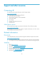
Support and other resources ·································································································································· 140 Contacting HP ······························································································································································ 140 Subscription service ············································································································································ 140 Related information ······················································································································································ 140 Documents ···························································································································································· 140 Websites······························································································································································· 140 Conventions ·································································································································································· 141 169H
370H
170H
371H
17H
372H
172H
37H
173H
374H
174H
375H
175H
376H
Index ········································································································································································ 143 176H
37H
iv
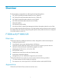
Overview
This documentation is applicable to the following firewall and UTM products:
•
HP F1000-S-EI firewall (hereinafter referred to as the F1000-S-EI)
•
HP F1000-A-EI firewall (hereinafter referred to as the F1000-A-EI)
•
HP F1000-E firewall (hereinafter referred to as the F1000-E)
•
HP F5000 firewall (hereinafter referred to as the F5000)
•
HP firewall modules
•
HP Enhanced firewall modules
•
HP U200-A/U200-S Unified Threat Management Products (hereinafter referred to as the UTM)
You can configure most of the firewall functions in the Web interface and some functions at the command
line interface (CLI). Each function configuration guide specifies clearly whether the function is configured
in the Web interface or at the CLI.
F1000-A-EI/F1000-S-EI
Overview
F1000-A-EI/F1000-S-EI a leading firewall device of HP, is designed for medium-sized enterprises.
•
Traditional firewall functions
•
Virtual firewall, security zone, attack protection, URL filtering
•
Application Specific Packet Filter (ASPF), which can monitor connection processes and user
operations and provide dynamic packet filtering together with ACLs.
•
Multiple types of VPN services, such as IPsec VPN
•
RIP/OSPF/BGP routing
•
Stateful failover (Active/Active and Active/Standby mode)
•
Inside-chassis temperature detection
•
Management by its own Web-based management system and IMC
F1000-A-EI/F1000-S-EI uses a multi-core processor and provides the following interfaces:
•
12 combo interfaces, for fiber/copper port switching
•
Two expansion slots, which support the 2*10GE fiber interface module (NSQ1XS2U0).
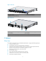
Appearance
F1000-A-EI and F1000-S-EI have similar front and rear views.
1
Figure 1 Front view
1: Combo interfaces
2: Console port (CONSOLE)
3: USB port (reserved for future use)
Figure 2 Rear view
1
2
3
5
4
1: Power module slot 1 (PWR1) (supports AC/DC
power modules)
2: Power module slot 2 (PWR2) (supports AC/DC
power modules)
3: Interface module slot 2(Slot 2)
4: Grounding screw
5: Interface module slot 1 (Slot 1) (A NSQ1XS2U0 interface module can be installed only to slot 1)
F1000-E
Overview
The F1000-E is designed for large- and medium-sized networks. It supports the following functions:
•
Traditional firewall functions
•
Virtual firewall, security zone, attack protection, URL filtering
•
Application Specific Packet Filter (ASPF), which can monitor connection processes and user
operations and provide dynamic packet filtering together with ACLs.
•
Multiple types of VPN services, such as IPsec VPN
•
RIP/OSPF/BGP routing
•
Power module redundancy backup (AC+AC or DC+DC)
•
Stateful failover (Active/Active and Active/Standby mode)
•
Inside-chassis temperature detection
2
Support for management by its own Web-based management system or by IMC
•
The F1000-E uses a multi-core processor and provides the following interfaces:
•
Four combo interfaces, for fiber/copper port switching
•
Two interface module expansion slots, which support the following interface modules: 4GBE, 8GBE,
1EXP, and 4GBP.
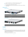
Appearance
Figure 3 Front view
1: AC power switch (ON/OFF)
2: RPS receptacle (RPS)
3: CF card slot (CF CARD)
4: Device-mode USB port 1 (USB 1)
5: Host-mode USB port 0 (USB 0)
6: Console port (CONSOLE)
7: AUX port (AUX)
8: AC-input power receptacle (–100 to 240 VAC @ 50 or 60 Hz; 2.5 A)
Figure 4 Rear view
1: Grounding screw and sign
2: Combo interfaces (0 to 3)
3: Interface module slot 2
4: Interface module slot 1
F5000
Overview
The F5000 provides security protection for large enterprises, carriers, and data centers. It adopts
multi-core multi-threaded and ASIC processors to construct a distributed architecture, which allows for the
separation of the system management and service processing, making it a firewall that has the highest,
distributed security processing capability.
The F5000 supports the following functions and features:
3
•
Protection against external attacks, internal network protection, traffic monitoring, email filtering,
Web filtering, application layer filtering
•
ASPF
•
Multiple types of VPN services, such as L2TP VPN, GRE VPN, IPsec VPN, and dynamic VPN
•
RIP/OSPF/BGP routing, routing policy, and policy-based routing
•
Power module 1+1 redundancy backup (AC+AC or DC+DC)
•
Multiple types of service interface modules
•
High availability functions, such as stateful failover and VRRP
Appearance
Figure 5 Front view
1: MPU slot (Slot 0)
2: Fan tray slot
3: Power module slot 1 (PWR1)
4: PoE power module filler panel (reserved for future
PoE support)
5: Power module slot 2 (PWR2)
6: Grounding screw and sign
7: Interface module slots (Slot 1 through Slot 4)
4
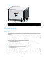
Figure 6 Rear view
1: Rear chassis cover handle (do not use this handle to lift the chassis)
2: (Optional) Air filter
3: Chassis handle
4: Grounding screw and sign
5: Air vents
Firewall modules
Overview
The firewall modules are developed based on the Open Application Architecture (OAA) for carrier-level
customers.
A firewall module can be installed in the HP 5800/7500E/9500E/12500 Switch or a 6600/8800
router. A switch or router can be installed with multiple firewall modules to expand the firewall processing
capability for future use. The main network device (switch or router) and the firewall modules together
provide highly integrated network and security functions for large networks.
The firewall modules support the following functions and features:
•
Traditional firewall functions
•
Virtual firewall, security zone, attack protection, URL filtering
•
Application Specific Packet Filter (ASPF), which can monitor connection processes and user
operations and provide dynamic packet filtering together with ACLs.
•
Multiple types of VPN services, such as IPsec VPN
•
RIP/OSPF/BGP routing
A firewall module provides two GE ports and two GE combo interfaces, which can be used as
management ports and stateful failover ports. It is connected to the main network device through the
internal 10GE port. The HP main network device's rear card has the line-speed forwarding capability,
ensuring fast data forwarding with the firewall module. The firewall modules are equipped with
dedicated, multi-core processors and high-speed caches. They can process security services without
impacting performances of the main network devices.
5
Appearance
Figure 7 Firewall module for 5800 switches
Figure 8 Firewall module for 7500E/9500E/12500 switches
Figure 9 Firewall module for 6600/8800 routers
Enhanced firewall modules
The Enhanced firewall module is a new-generation firewall module developed based on the 40G
hardware platform to meet the security-network integration trend and satisfy the ultra-10G Ethernet
bandwidth requirements. It is the first model of ultra-10G firewall module in the industry and can be used
in HP 10500/12500 Ethernet switches. Using the Enhanced firewall module, you can implement security
functions (such as firewall and VPN) in the HP 10500/12500 switches, integrating security protection
with network functions.
The Enhanced firewall module supports the following functions:
6
•
External attack protection, internal network protection, traffic monitoring, URL filtering, application
layer filtering.
•
ASPF
•
Email alarm, attack log, stream log, and network management monitoring.
•
Stateful failover (Active/Active and Active/Standby mode), implementing load sharing and service
backup.
UTM products
Overview
The HP UTM products are a new generation of professional security devices developed by HP for
enterprises. They fall into the following categories:
•
U200-A: For small- to medium-sized enterprises and branches.
•
U200-S: For small enterprises and branches.
The UTM products are based on a high-performance multi-core and multi-thread security platform, and
deliver the most comprehensive suite of firewall and virtual private network (VPN) features in the industry:
•
Support for security zones, static and dynamic blacklist functions, MAC address–IP address binding,
and security zone-based access control and attack protection that can defend against attacks such
as ARP spoofing, attacks exploiting TCP flag bits, large ICMP packet attacks, SYN flood attacks,
and address scanning and port scanning. These products also provide the stateful application
specific packet filter (ASPF) feature, which can monitor the connection setup process, detect invalid
operations, and cooperate with ACLs to complete packet filtering.
•
Support for various VPN solutions, such as IP security (IPsec) VPN, Layer 2 Tunneling Protocol (L2TP)
VPN and Generic Routing Encapsulation (GRE) VPN. You can use these functions to construct
various VPNs.
•
Support for static routing, policy-based routing, and dynamic routing such as Routing Information
Protocol (RIP) and Open Shortest Path First (OSPF).
•
Support for virtual firewalls, which can effectively save the deployment cost.
The new-generation firewalls not only provide powerful firewall functions, but also support advanced
functions that can help achieve higher network security, which include intrusion detection and protection,
gateway anti-virus, Point-to-point (P2P) traffic control, and universal resource locator (URL) filtering.
The UTM products have the advantages of high reliability and availability. They support stateful failover,
sensing of temperature in the chassis, and are available with AC power modules. In addition, they
support network management, and provide a Web management interface, fully satisfying requirements
for network maintenance, upgrade, and optimization.
U200-A supports two types of interface modules: NSQ1GT2UA0 and NSQ1GP4U0. Each U200-A
provides two MIM expansion slots for future interfacing and service expansion.
U200-S supports one type of interface module: 2GE. Each product provides one interface slot for future
interfacing and service expansion.
7
Appearance
U200-A
Figure 10 U200-A front view
1: Copper Ethernet ports (GE0 to GE5)
2: Console port (CONSOLE)
3: USB port
4: CF ejector button
5: CF card slot
Figure 11 U200-A rear view
1: Grounding screw and sign
2: Power switch (ON/OFF)
3: AC-input power receptacle
4: Interface module slot 1 (SLOT1)
5: Interface module slot 2 (SLOT2)
8
U200-S
Figure 12 U200-S front view
1: Copper Ethernet ports (GE0 to GE4)
2: Console port (CONSOLE)
3: USB port
4: CF ejector button
5: CF card slot
Figure 13 U200-S rear view
1: AC-input power receptacle
2: Interface module slot (SLOT)
3: Grounding screw and sign
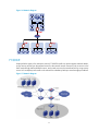
Application scenarios
F1000-A-EI/F1000-S-EI
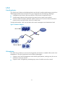
Firewall application
With powerful filtering and management functions, the F1000-A-EI/F1000-S-EI can be deployed at the
egress of an internal network to defend against external attacks and control internal access by
separating security zones.
9
Figure 14 Network diagram
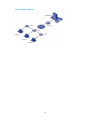
Virtual firewall application
The F1000-A-EI/F1000-S-EI supports the virtual firewall function. You can create multiple virtual firewalls
on one firewall. Each virtual firewall can have its own security policy and can be managed
independently.
Figure 15 Network diagram
VPN application
The F1000-A-EI/F1000-S-EI supports VPN functions, helping branch offices and remote users securely
access the resources in the headquarters and those in their own networks.
10
Figure 16 Network diagram
F1000-E
Deployed at the egress of an enterprise network, F1000-E firewalls can protect against external attacks,
ensure security access from the external network to the internal network resources (such as servers in the
DMZ zone) through NAT and VPN functions, and control access to the internal network by using security
zones. You can deploy two firewalls in the network for redundancy backup to avoid a single point failure.
Figure 17 Network diagram
11
F5000
Large data centers are connected to the 10G core network usually through a 10G Ethernet. The F5000
firewall has a 10G processing capability and abundant port features. It can be deployed at the egress
of a network to protect security for the internal network. You can deploy two firewalls to implement
stateful failover.
•
Active-active stateful failover can balance user data.
•
Active-standby stateful failover improves availability of the firewalls. They back up each other to
avoid a single point failure.
Figure 18 Network diagram
Firewall modules
Firewall modules work with the main network devices (such as 5800/7500/9500/12500 switches and
6600/8800 routers). Deployed at the egress of a network, the firewall modules can protect against
external attacks and implement security access control of the internal network by using security zones.
You can meet the development of the network simply by installing more firewall modules to a switch or
router. Deploying two switches/routers with the firewall modules in the network can improve service
availability.
12
Figure 19 Network diagram
Enhanced firewall modules
Clound computing data center application
The Enhanced firewall modules can provide high-performance firewall functions. They also support the
virtual firewall function. An Enhanced firewall module can be virtualized into multiple logical firewalls.
Each virtual firewall has its own security policy and is managed independently. The virtual firewall
function well satisfies the multi-tenant requirements in cloud computing data centers.
Figure 20 Network diagram
13
Enterprise network applicatoin
Deployed in the core switch or the aggregation switch of an enterprise network, the Enhanced firewall
module provides security isolation and control of the network zones.
Working with the 10500/12500 switch, the Enhanced firewall module can act as the network edge
device to protect against external attacks, or as the internal network access control device to isolate
different security zones.
Figure 21 Network diagram
Remote access application
The Enhanced firewall module supports VPN functions, helping branch offices and remote users securely
access the resources in the headquarters
Figure 22 Network diagram
14
UTM
Firewall application
The UTM Security Products can be deployed at the exits of small- to medium-sized enterprise networks to
defend against attacks from the Internet. This type of application has the following advantages:
•
Integrated security functions that can protect the whole network at application layer.
•
Powerful attack protection that can protect the internal servers against various attacks.
•
Network Address Translation (NAT) that enables internal users to access the Internet and allows
internal servers to provide various services for external users.
Friendly Web interface, which can help reduce the network management and maintenance load.
Figure 23 Network diagram
VPN application
The UTM Security Products can be used as the gateways of branches to establish VPN tunnels to the
Headquarters. This type of application has the following advantages:
•
Supports various NAT and Application Level Gateway (ALG) features, making it easy for users at
branches to access the network.
•
Supports various VPN gateways, facilitating easy access of mobile users to the network.
15
Figure 24 Network diagram
16
Login overview
This chapter describes the available login methods and introduces the related concepts.
Login methods at a glance
You can access the device through the console port or the Web interface at the first login. After login, you
can configure other login methods on the device, such as AUX, Telnet, and SSH.
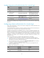
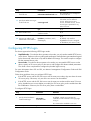
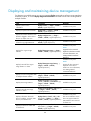
Table 1 Login methods
Login method
Default setting and configuration requirements
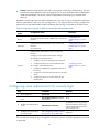
Logging in to the CLI:
• Logging in through the console
port for the first time
By default, login through the console port is enabled, no username or
password is required, and the user privilege level is 3.
By default, Telnet service is disabled.
• Logging in through Telnet
To use Telnet service, you only need to enable the Telnet server
function. After you enable the Telnet server function ,a user can log in
to the device through Telnet with the IP address 192.168.0.1/24 (the
IP address of interface GigabitEthernet 0/0), the username admin, the
password admin, and the user privilege level 3.
By default, SSH service is disabled. To use SSH service, complete the
following configuration tasks:
• Enable the SSH server function and configure SSH attributes.
• Assign an IP address to an interface of the device and make sure
• Logging in through SSH
the interface and the SSH client can reach each other. By default,
only interface GigabitEthernet 0/0 is assigned an IP address
(192.168.0.1/24).
• Configure scheme authentication for VTY login users (scheme
authentication by default).
• Configure the user privilege level of VTY login users (0 by default).
Local login through the AUX port
By default, login through the AUX port is disabled. To enable AUX
login, log in to the device through the console port, and configure the
password for the default password authentication mode, or change
the authentication mode and configure parameters for the new
authentication mode.
NOTE:
Support for this login method depends on the device model. For more
information, see "Configuring none authentication for AUX login."
Logging in to the Web interface
By default, you can log in to the Web interface of the device with the
IP address 192.168.0.1/24 (the IP address of interface
GigabitEthernet 0/0), the username admin, and the password admin.
17
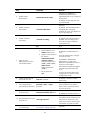
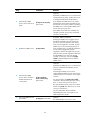
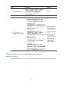
Login method
Default setting and configuration requirements
By default, SNMP login is disabled. To use SNMP service, complete
the following configuration tasks:
• Assign an IP address to an interface of the device and make sure
the interface and the NMS can reach each other. By default, only
interface GigabitEthernet 0/0 is assigned an IP address
(192.168.0.1/24).
Accessing the device through SNMP
• Configure SNMP basic parameters.
Logging in to the firewall module from
the network device
After configuring the network device and the firewall module
properly, you can log in to the firewall module from the network
device.
CLI user interfaces
The device uses user interfaces (also called "lines") to control CLI logins and monitor CLI sessions. You
can configure access control settings, including authentication, user privilege, and login redirect on user
interfaces. After users are logged in, their actions must be compliant with the settings on the user
interfaces assigned to them.
Users are assigned different user interfaces, depending on their login methods, as shown in Table 2.
Table 2 CLI login method and user interface matrix
User interface
Login method
Console user interface
Console port (EIA/TIA-232 DCE)
AUX user interface
AUX port (EIA/TIA-232 DTE, typically used for dial-in access
through modems)
Virtual type terminal (VTY) user interface
Telnet or SSH
User interface assignment
The device automatically assigns user interfaces to CLI login users, depending on their login methods.
Each user interface can be assigned to only one user at a time. If no user interface is available, a CLI
login attempt will be rejected.
For a CLI login, the device always picks the lowest numbered user interface from the idle user interfaces
available for the type of login. For example, four VTY user interfaces (0 to 3) are configured, of which
VTY 0 and VTY 3 are idle. When a user Telnets to the device, the device assigns VTY 0 to the user and
uses the settings on VTY 0 to authenticate and manage the user.
User interface identification
A user interface can be identified by an absolute number, or the interface type and a relative number.
An absolute number uniquely identifies a user interface among all user interfaces. The user interfaces are
numbered starting from 0 and incrementing by 1 and in the sequence of console, AUX, and then VTY
user interfaces. You can use the display user-interface command without any parameters to view
supported user interfaces and their absolute numbers.
18
A relative number uniquely identifies a user interface among all user interfaces that are the same type.
The number format is user interface type + number:
•
Console user interface—CON0.
•
AUX user interface—AUX 0.
•
VTY user interfaces—Numbered starting from 0 and incrementing by 1.
19
Logging in to the CLI
By default, the first time you access the CLI you must log in through the console port. At the CLI, you can
configure Telnet or SSH for remote access.
Logging in through the console port for the first time
To log in through the console port, make sure the console terminal has a terminal emulation program (for
example, HyperTerminal in Windows XP). In addition, the port settings of the terminal emulation
program must be the same as the default settings of the console port in Table 3.
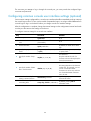
Table 3 Default console port properties
Parameter
Default
Bits per second
9600 bps
Flow control
None
Parity
None
Stop bits
1
Data bits
8
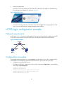
To log in through the console port from a console terminal (for example, a PC):
1.
Connect the DB-9 female connector of the console cable to the serial port of the PC.
2.
Connect the RJ-45 connector of the console cable to the console port of the device.
IMPORTANT:
• Identify the mark on the console port and make sure you are connecting to the correct port.
• The serial ports on PCs do not support hot swapping. If the device has been powered on, always connect
the console cable to the PC before connecting it to the device, and when you disconnect the cable, first
disconnect it from the device.
Figure 25 Connecting a terminal to the console port
3.
If the PC is off, turn on the PC.
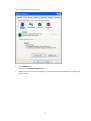
4.
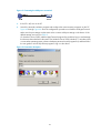
Launch the terminal emulation program and configure the communication properties on the PC.
Figure 26 through Figure 28 show the configuration procedure on Windows XP HyperTerminal.
Make sure the port settings are the same as listed in Table 3.
On Windows Server 2003, add the HyperTerminal program first, and then log in to and manage
the device as described in this document. On Windows Server 2008, Windows 7, Windows Vista,
or some other operating system, obtain a third-party terminal control program first, and then follow
the user guide or online help to log in to the device.
20
Figure 26 Connection description
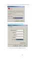
Figure 27 Specifying the serial port used to establish the connection
21
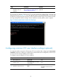
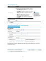
Figure 28 Setting the properties of the serial port
5.
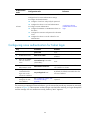
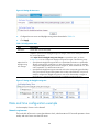
Power on the device and press Enter at the prompt.
Figure 29 CLI
6.
At the default user view prompt <HP>, enter commands to configure the device or view the running
status of the device. To get help, enter ?.
Configuring console login control settings
The following authentication modes are available for controlling console logins:
•
None—Requires no authentication. This mode is insecure.
•
Password—Requires password authentication.
22
Scheme—Uses the AAA module to provide local or remote console login authentication. You must
provide a username and password for accessing the CLI. For more information about authentication
modes and parameters, see Access Control Configuration Guide. Keep your username and
password.
•
By default, console login does not require authentication. Any user can log in through the console port
without authentication and have user privilege level 3. To improve device security, configure the
password or scheme authentication mode immediately after you log in to the device for the first time.
Table 4 Configuration required for different console login authentication modes
Authentication
mode
Configuration tasks
Reference
None
Set the authentication mode to none for the console user
interface.
"Configuring none
authentication for console
login"
Password
Enable password authentication on the console user
interface.
"Configuring password
authentication for console
login"
Set a password.
Enable scheme authentication on the console user
interface.
Configure local or remote authentication settings.
To configure local authentication:
Scheme
1.
Configure a local user and specify the password.
2.
Configure the device to use local authentication.
"Configuring scheme
authentication for console
login"
To configure remote authentication:
3.
Configure the RADIUS or HWTACACS scheme on
the device.
4.
Configure the username and password on the AAA
server.
5.
Configure the device to use the scheme for user
authentication.
Configuring none authentication for console login
Step
Command
Remarks
6.
Enter system view.
system-view
N/A
7.
Enter console user interface
view.
user-interface console first-number
[ last-number ]
N/A
8.
Enable none authentication
mode.
authentication-mode none
By default, you can log in to the
device through the console port
without authentication and have
user privilege level 3.
9.
Configure common settings
for console login.
See "Configuring common console
user interface settings (optional)."
Optional.
The next time you attempt to log in through the console port, you do not need to provide any username
or password.
23
Configuring password authentication for console login
Step
Command
Remarks
1.
Enter system view.
system-view
N/A
2.
Enter console user interface
view.
user-interface console first-number
[ last-number ]
N/A
3.
Enable password
authentication.
authentication-mode password
By default, you can log in to the
device through the console port
without authentication and have
user privilege level 3 after login.
4.
Set a password.
set authentication password
{ cipher | simple } password
By default, no password is set.
5.
Configure common settings
for console login.
See "Configuring common console
user interface settings (optional)."
Optional.
The next time you attempt to log in through the console port, you must provide the configured login
password.
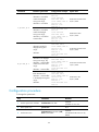
Configuring scheme authentication for console login
When scheme authentication is used, you can choose to configure the command authorization and
command accounting functions.
If command authorization is enabled, a command is available only if the user has the commensurate user
privilege level and is authorized to use the command by the AAA scheme.
Command accounting allows the HWTACACS server to record all commands executed by users,
regardless of command execution results. This function helps control and monitor user behaviors on the
device. If command accounting is enabled and command authorization is not enabled, every executed
command is recorded on the HWTACACS server. If both command accounting and command
authorization are enabled, only the authorized and executed commands are recorded on the
HWTACACS server.
Follow these guidelines when you configure scheme authentication for console login:
•
To make the command authorization or command accounting function take effect, apply an
HWTACACS scheme to the intended ISP domain. This scheme must specify the IP address of the
authorization server and other authorization parameters.
•
If the local authentication scheme is used, use the authorization-attribute level level command in
local user view to set the user privilege level on the device.
•
If a RADIUS or HWTACACS authentication scheme is used, set the user privilege level on the
RADIUS or HWTACACS server.
To configure scheme authentication for console login:
Step
Command
Remarks
1.
Enter system view.
system-view
N/A
2.
Enter console user interface
view.
user-interface console first-number
[ last-number ]
N/A
24
Step
3.
Enable scheme
authentication.
Command
Remarks
authentication-mode scheme
Whether local, RADIUS, or
HWTACACS authentication is
adopted depends on the configured
AAA scheme.
By default, console login users are
not authenticated.
Optional.
4.
Enable command
authorization.
command authorization
By default, command authorization
is disabled. The commands
available for a user only depend on
the user privilege level.
Optional.
5.
Enable command
accounting.
command accounting
6.
Exit to system view.
quit
By default, command accounting is
disabled. The accounting server
does not record the commands
executed by users.
N/A
Optional.
7.
Apply an AAA
authentication scheme to
the intended domain.
a. Enter ISP domain view:
domain domain-name
By default, local authentication is
used.
b. Apply an AAA scheme to
the domain:
authentication default
{ hwtacacs-scheme
hwtacacs-scheme-name
[ local ] | local | none |
radius-scheme
radius-scheme-name
[ local ] }
For local authentication, configure
local user accounts.
c. Exit to system view:
quit
For RADIUS or HWTACACS
authentication, configure the
RADIUS or HWTACACS scheme on
the device and configure
authentication settings (including the
username and password) on the
server.
For more information about AAA
configuration, see Access Control
Configuration Guide.
8.
Create a local user and
enter local user view.
local-user user-name
By default, a local user named
admin exists.
9.
Set an authentication
password for the local user.
password { cipher | simple }
password
By default, the password for
system-predefined user admin is
admin, and no password is set for
any other local user.
10. Specifies a command level
of the local user.
authorization-attribute level level
Optional.
By default, the command level is 0.
11. Specify terminal service for
the local user.
service-type terminal
By default, the system-predefined
user admin can use terminal service,
Telnet service, SSH service, and
Web service, and no service type is
specified for any other local user.
12. Configure common settings
for console login.
See "Configuring common console
user interface settings (optional)."
Optional.
25
The next time you attempt to log in through the console port, you must provide the configured login
username and password.
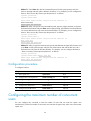
Configuring common console user interface settings (optional)
Some common settings configured for a console user interface take effect immediately and can interrupt
the console login session. To save you the trouble of repeated re-logins, use a login method different from
console login to log in to the device before you change console user interface settings.
After the configuration is complete, change the terminal settings on the configuration terminal and make
sure they are the same as the settings on the device.
To configure common settings for a console user interface:
Step
Command
Remarks
1.
Enter system view.
system-view
N/A
2.
Enter console user interface
view.
user-interface console first-number
[ last-number ]
N/A
3.
Set the baud rate.
speed speed-value
By default, the baud rate is 9600
bps.
4.
Specify the parity check
mode.
parity { even | mark | none | odd
| space }
The default setting is none, namely,
no parity check.
5.
Specify the number of stop
bits.
The default is 1.
stopbits { 1 | 1.5 | 2 }
Stop bits indicate the end of a
character. The more the stop bits, the
slower the transmission.
The default is 8.
The setting depends on the character
coding type. For example, you can
set it to 7 if standard ASCII
characters are to be sent, and set it
to 8 if extended ASCII characters
are to be sent.
6.
Specify the number of data
bits in each character.
databits { 5 | 6 | 7 | 8 }
7.
Define the shortcut key for
starting a terminal session.
activation-key character
By default, you press Enter to start
the terminal session.
8.
Define a shortcut key for
terminating tasks.
escape-key { default | character }
By default, pressing Ctrl+C
terminates a task.
26
Step
Command
Remarks
By default, the terminal display type
is ANSI.
9.
Specify the terminal display
type.
10. Configure the user privilege
level for login users.
terminal type { ansi | vt100 }
user privilege level level
11. Set the maximum number of
lines to be displayed on a
screen.
screen-length screen-length
12. Set the size of command
history buffer.
history-command max-size value
13. Set the idle-timeout timer.
idle-timeout minutes [ seconds ]
The device supports two types of
terminal display: ANSI and VT100.
HP recommends setting the display
type of both the device and the
terminal to VT100. If the device and
the client use different display types
(for example, HyperTerminal or
Telnet terminal) or both are set to
ANSI, when the total number of
characters of the currently edited
command line exceeds 80, an
anomaly such as cursor corruption
or abnormal display of the terminal
display might occur on the client.
By default, the default command
level is 3 for the console user
interface.
By default, a screen displays 24
lines at most.
A value of 0 disables pausing
between screens of output.
By default, the buffer saves 10
history commands at most.
The default idle-timeout is 10
minutes. The system automatically
terminates the user's connection if
there is no information interaction
between the device and the user
within the idle-timeout time.
Setting idle-timeout to 0 disables the
idle-timeout function.
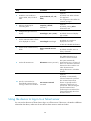
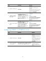
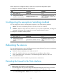
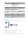
Logging in through Telnet
NOTE:
Telnet login is not supported in FIPS mode.
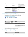
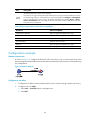
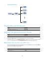
You can Telnet to the device for remote management, or use the device as a Telnet client to Telnet to other
devices, as shown in Figure 30.
Figure 30 Telnet login
27
Table 5 shows the Telnet server and client configuration required for a successful Telnet login.
Table 5 Telnet server and Telnet client configuration requirements
Device role
Requirements
Enable Telnet server.
Telnet server
Assign an IP address to an interface of the device, and make sure the Telnet
server and client can reach each other. By default, only interface
GigabitEthernet 0/0 is assigned an IP address (192.168.0.1/24).
Configure the authentication mode and other settings.
Telnet client
Run the Telnet client program.
Obtain the IP address of the interface on the server.
To control Telnet access to the device operating as a Telnet server, configure login authentication and
user privilege levels for Telnet users.
By default, password authentication applies to Telnet login. To allow Telnet access to the device after you
enable the Telnet server, you must configure scheme authentication.
The following are authentication modes available for controlling Telnet logins:
•
None—Requires no authentication and is insecure.
•
Password—Requires a password for accessing the CLI. If your password was lost, log in to the
device through the console port to re-set the password.
•
Scheme—Uses the AAA module to provide local or remote authentication. You must provide a
username and password for accessing the CLI. If the password configured in the local user
database was lost, log in to the device through the console port and re-set the password. If the
username or password configured on a remote server was lost, contact the server administrator for
help.
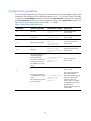
Table 6 Configuration required for different Telnet login authentication modes
Authentication
mode
Configuration tasks
Reference
None
Set the authentication mode to none for the VTY user
interface.
"Configuring none
authentication for Telnet
login"
Password
Enable password authentication on the VTY user
interface.
Set a password.
28
"Configuring password
authentication for Telnet
login"
Authentication
mode
Configuration tasks
Reference
Enable scheme authentication on the VTY user interface.
Configure local or remote authentication settings.
To configure local authentication:
14. Configure a local user and specify the password.
15. Configure the device to use local authentication.
Scheme
To configure remote authentication:
16. Configure the RADIUS or HWTACACS scheme on
the device.
"Configuring scheme
authentication for Telnet
login"
17. Configure the username and password on the AAA
server.
18. Configure the device to use the scheme for user
authentication.
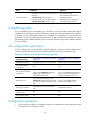
Configuring none authentication for Telnet login
Step
Command
Remarks
1.
Enter system view.
system-view
N/A
2.
Enable Telnet server.
telnet server enable
By default, the Telnet server function is
disabled.
3.
Enter one or multiple
VTY user interface
views.
user-interface vty first-number
[ last-number ]
N/A
4.
Enable none
authentication mode.
authentication-mode none
By default, the authentication mode for VTY
user interfaces is scheme.
5.
Configure the
command level for
login users on the
current user interfaces.
user privilege level level
By default, the default command level is 0 for
VTY user interfaces.
Configure common
settings for the VTY
user interfaces.
See "Configuring common VTY
user interface settings
(optional)."
Optional.
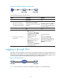
6.
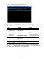
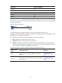
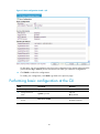
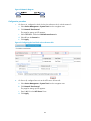
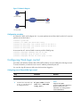
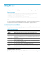
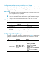
The next time you attempt to Telnet to the device, you do not need to provide any username or password,
as shown in Figure 31. If the maximum number of login users has been reached, your login attempt fails
and the message "All user interfaces are used, please try later!" appears.
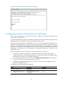
29
Figure 31 Telnetting to the device without authentication
Configuring password authentication for Telnet login
Step
Command
Remarks
1.
Enter system view.
system-view
N/A
2.
Enable Telnet server.
telnet server enable
By default, the Telnet server
function is disabled.
3.
Enter one or multiple VTY
user interface views.
user-interface vty first-number
[ last-number ]
N/A
4.
Enable password
authentication.
authentication-mode password
By default, the authentication
mode for the VTY user interfaces
is scheme.
5.
Set a password.
set authentication password { cipher |
simple } password
By default, no password is set.
6.
Configure the user privilege
level for login users.
user privilege level level
The default level is 0.
7.
Configure common settings
for VTY user interfaces.
See "Configuring common VTY user
interface settings (optional)."
Optional.
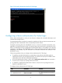
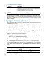
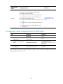
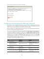
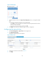
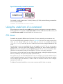
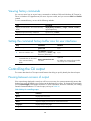
The next time you attempt to Telnet to the device, you must provide the configured login password, as
shown in Figure 32. If the maximum number of login users has been reached, your login attempt fails and
the message "All user interfaces are used, please try later!" appears.
30
Figure 32 Password authentication interface for Telnet login
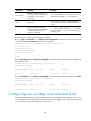
Configuring scheme authentication for Telnet login
When scheme authentication is used, you can choose to configure the command authorization and
command accounting functions.
If command authorization is enabled, a command is available only if the user has the commensurate user
privilege level and is authorized to use the command by the AAA scheme.
Command accounting allows the HWTACACS server to record all commands executed by users,
regardless of command execution results. This function helps control and monitor user behaviors on the
device. If command accounting is enabled and command authorization is not enabled, every executed
command is recorded on the HWTACACS server. If both command accounting and command
authorization are enabled, only the authorized and executed commands are recorded on the
HWTACACS server.
Follow these guidelines when you configure scheme authentication for Telnet login:
•
To make the command authorization or command accounting function take effect, apply an
HWTACACS scheme to the intended ISP domain. This scheme must specify the IP address of the
authorization server and other authorization parameters.
•
If the local authentication scheme is used, use the authorization-attribute level level command in
local user view to set the user privilege level on the device.
•
If a RADIUS or HWTACACS authentication scheme is used, set the user privilege level on the
RADIUS or HWTACACS server.
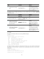
To configure scheme authentication for Telnet login:
Step
Command
Remarks
1.
Enter system view.
system-view
N/A
2.
Enable Telnet server.
telnet server enable
By default, the Telnet server function is
disabled.
31
Step
3.
4.
Enter one or multiple
VTY user interface views.
Enable scheme
authentication.
Command
Remarks
user-interface vty first-number
[ last-number ]
N/A
authentication-mode scheme
Whether local, RADIUS, or
HWTACACS authentication is adopted
depends on the configured AAA
scheme.
By default, local authentication is
adopted.
Optional.
5.
Enable command
authorization.
command authorization
By default, command authorization is
disabled. The commands available for
a user only depend on the user
privilege level.
Optional.
6.
Enable command
accounting.
command accounting
7.
Exit to system view.
quit
8.
Apply an AAA
authentication scheme to
the intended domain.
N/A
a. Enter ISP domain view:
domain domain-name
Optional.
b. Apply an AAA scheme to
the domain:
authentication default
{ hwtacacs-scheme
hwtacacs-scheme-name
[ local ] | local | none |
radius-scheme
radius-scheme-name
[ local ] }
For local authentication, configure
local user accounts.
c. Exit to system view:
quit
9.
Create a local user and
enter local user view.
By default, command accounting is
disabled. The accounting server does
not record the commands executed by
users.
By default, local authentication is used.
For RADIUS or HWTACACS
authentication, configure the RADIUS
or HWTACACS scheme on the device
and configure authentication settings
(including the username and
password) on the server.
For more information about AAA
configuration, see Access Control
Configuration Guide.
local-user user-name
By default, a local user named admin
exists.
10. Set a password.
password { cipher | simple }
password
By default, the password for
system-predefined user admin is
admin, and no password is set for any
other local user.
11. Specify the command
level of the local user.
authorization-attribute level level
Optional.
By default, the command level is 0.
12. Specify Telnet service for
the local user.
service-type telnet
By default, the system-predefined user
admin can use terminal service, Telnet
service, SSH service, and Web service,
and no service type is specified for any
other local user.
13. Exit to system view.
quit
N/A
32
Step
Command
Remarks
14. Configure common
settings for VTY user
interfaces.
See "Configuring common VTY user
interface settings (optional)."
Optional.
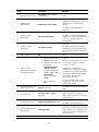
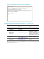
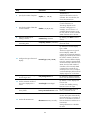
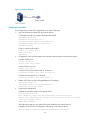
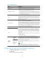
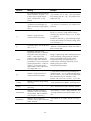
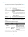
The next time you attempt to Telnet to the CLI, you must provide the configured login username and
password, as shown in Figure 33. If you are required to pass a second authentication, you must also
provide the correct password to access the CLI. If the maximum number of login users has been reached,
your login attempt fails and the message "All user interfaces are used, please try later!" appears.
Figure 33 Scheme authentication interface for Telnet login
Configuring common VTY user interface settings (optional)
You might be unable to access the CLI through a VTY user interface after configuring the auto-execute
command command on it. Before you configure the command and save the configuration, make sure you
can access the CLI through a different user interface.
To configure common settings for VTY user interfaces:
Step
Command
Remarks
1.
Enter system view.
system-view
N/A
2.
Enter one or multiple VTY user
interface views.
user-interface vty first-number
[ last-number ]
N/A
3.
Enable the terminal service.
Optional.
shell
By default, terminal service is
enabled.
33
Step
Command
Remarks
Optional.
Enable the user interfaces to
support Telnet, SSH, or both of
them.
protocol inbound { all | ssh |
telnet }
5.
Define a shortcut key for
terminating tasks.
escape-key { default |
character }
6.
Configure the type of terminal
display.
7.
Set the maximum number of lines
to be displayed on a screen.
4.
By default, both Telnet and SSH
are supported.
The configuration takes effect the
next time you log in.
Optional.
By default, pressing Ctrl+C
terminates a task.
Optional.
terminal type { ansi | vt100 }
By default, the terminal display
type is ANSI.
Optional.
screen-length screen-length
By default, up to 24 lines is
displayed on a screen.
A value of 0 disables the function.
8.
Set the size of command history
buffer.
history-command max-size
value
Optional.
By default, the buffer saves 10
history commands.
Optional.
The default idle-timeout is 10
minutes for all user interfaces.
9.
Set the idle-timeout timer.
idle-timeout minutes [ seconds ]
The system automatically
terminates the user's connection if
there is no information interaction
between the device and the user
within the timeout time.
Setting idle-timeout to 0 disables
the timer.
Optional.
By default, no automatically
executed command is specified.
10. Specify a command to be
automatically executed when a
user logs in to the user interfaces.
auto-execute command
command
The command auto-execute
function is typically used for
redirecting a Telnet user to a
specific host. After executing the
specified command and
performing the incurred task, the
system automatically disconnect
the Telnet session.
Using the device to log in to a Telnet server
You can use the device as a Telnet client to log in to a Telnet server. If the server is located in a different
subnet than the device, make sure the two devices have routes to reach each other.
34
Figure 34 Telnetting from the device to a Telnet server
To use the device to log in to a Telnet server:
Step
Command
Remarks
N/A
1.
Enter system view.
system-view
2.
Specify the source IPv4
address or source interface
for outgoing Telnet packets.
telnet client source { interface
interface-type interface-number | ip
ip-address }
By default, no source IPv4 address
or source interface is specified.
The device automatically selects a
source IPv4 address.
3.
Exit to user view.
quit
N/A
Optional.
• Log in to an IPv4 Telnet server:
4.
Use the device to log in to a
Telnet server.
telnet remote-host
[ service-port ] [ vpn-instance
vpn-instance-name ] [ source
{ interface interface-type
interface-number | ip
ip-address } ]
• Log in to an IPv6 Telnet server:
telnet ipv6 remote-host [ -i
interface-type
interface-number ]
[ port-number ] [ vpn-instance
vpn-instance-name ]
Use either command.
NOTE:
Support for the telnet ipv6
command depends on the device
model. For more information, see
Getting Started Command
Reference.
Logging in through SSH
SSH offers a secure approach to remote login. By providing encryption and strong authentication, it
protects devices against attacks such as IP spoofing and plain text password interception. You can use an
SSH client to log in to the device operating as an SSH server for remote management, as shown in Figure
35. You can also use the device as an SSH client to log in to an SSH server.
Figure 35 SSH login diagram
Table 7 shows the SSH server and client configuration required for a successful SSH login.
35
Table 7 SSH server and client requirements
Device role
Requirements
SSH server
Assign an IP address to an interface of the device, and make sure the interface
and the client can reach each other. By default, only interface GigabitEthernet
0/0 is assigned an IP address (192.168.0.1/24).
Configure the authentication mode and other settings.
SSH client
If a host operates as an SSH client, run the SSH client program on the host.
Obtain the IP address of the interface on the server.
To control SSH access to the device operating as an SSH server, configure authentication and user
privilege level for SSH users. By default, password authentication is adopted for SSH login, but no login
password is configured. To allow SSH access to the device after you enable the SSH server, you must
configure a password.
Configuring the SSH server on the device
When scheme authentication is used, you can choose to configure the command authorization and
command accounting functions.
If command authorization is enabled, a command is available only if the user has the commensurate user
privilege level and is authorized to use the command by the AAA scheme.
Command accounting allows the HWTACACS server to record all commands executed by users,
regardless of command execution results. This function helps control and monitor user behaviors on the
device. If command accounting is enabled and command authorization is not enabled, every executed
command is recorded on the HWTACACS server. If both command accounting and command
authorization are enabled, only the authorized and executed commands are recorded on the
HWTACACS server.
Follow these guidelines when you configure the SSH server:
•
To make the command authorization or command accounting function take effect, apply an
HWTACACS scheme to the intended ISP domain. This scheme must specify the IP address of the
authorization server and other authorization parameters.
•
If the local authentication scheme is used, use the authorization-attribute level level command in
local user view to set the user privilege level on the device.
•
If a RADIUS or HWTACACS authentication scheme is used, set the user privilege level on the
RADIUS or HWTACACS server.
The SSH client authentication method is password in this configuration procedure. For more information
about SSH and publickey authentication, see System Management and Maintenance Configuration
Guide.
To configure the SSH server on the device:
Step
Command
Remarks
1.
Enter system view.
system-view
N/A
2.
Create local key pairs.
public-key local create { dsa | rsa }
By default, no local key pairs are
created.
3.
Enable SSH server.
ssh server enable
By default, SSH server is disabled.
36
Step
Command
Remarks
4.
Enter one or multiple VTY user
interface views.
user-interface vty first-number
[ last-number ]
N/A
5.
Enable scheme
authentication.
authentication-mode scheme
By default, the authentication
mode for VTY user interfaces is
scheme.
6.
Enable the user interfaces to
support Telnet, SSH, or both
of them.
Optional.
protocol inbound { all | ssh }
By default, both Telnet and SSH
are supported.
Optional.
7.
Enable command
authorization.
command authorization
By default, command authorization
is disabled. The commands
available for a user only depend
on the user privilege level.
Optional.
8.
Enable command accounting.
command accounting
9.
Exit to system view.
quit
N/A
a. Enter the ISP domain view:
domain domain-name
10. Apply an AAA authentication
scheme to the intended
domain.
By default, command accounting is
disabled. The accounting server
does not record the commands
executed by users.
b. Apply the specified AAA
scheme to the domain:
authentication default
{ hwtacacs-scheme
hwtacacs-scheme-name
[ local ] | ldap-scheme
ldap-scheme-name
[ local ]| local | none |
radius-scheme
radius-scheme-name
[ local ] }
c. Exit to system view:
quit
Optional.
For local authentication, configure
local user accounts.
For RADIUS or HWTACACS
authentication, configure the
RADIUS or HWTACACS scheme
on the device and configure
authentication settings (including
the username and password) on
the server.
For more information about AAA
configuration, see Access Control
Configuration Guide.
11. Create a local user and enter
local user view.
local-user user-name
By default, a local user named
admin exists.
12. Set a password for the local
user.
password { cipher | simple }
password
By default, the password for
system-predefined user admin is
admin, and no password is set for
any other local user.
13. Specify the command level of
the user.
authorization-attribute level level
37
Optional.
By default, the command level is 0.
Step
Command
Remarks
14. Specify SSH service for the
user.
service-type ssh
By default, the system-predefined
user admin can use terminal
service, Telnet service, SSH
service, and Web service, and no
service type is specified for any
other local user.
15. Exit to system view.
quit
N/A
16. Create an SSH user, and
specify the authentication
mode for the SSH user.
ssh user username service-type
stelnet authentication-type
{ password | { any |
password-publickey | publickey }
assign publickey keyname }
N/A
17. Configure common settings
for VTY user interfaces.
See "Configuring common VTY
user interface settings (optional)."
Optional.
Using the device to log in to an SSH server
You can use the device as an SSH client to log in to an SSH server. If the server is located in a different
subnet than the device, make sure the two devices have routes to reach each other.
Figure 36 Logging in to an SSH client from the device
Perform the following tasks in user view:
Task
Command
Remarks
Log in to an IPv4 SSH server.
ssh2 server
The server argument represents the IPv4 address or
host name of the server.
The server argument represents the IPv6 address or
host name of the server.
Log in to an IPv6 SSH server.
ssh2 ipv6 server
NOTE:
Support for the ssh2 ipv6 command depends on the
device model. For more information, see Getting
Started Command Reference.
To work with the SSH server, you might need to configure the SSH client. For information about
configuring the SSH client, see Access Control Configuration Guide.
Local login through the AUX port
The following matrix shows the feature and hardware compatibility:
Hardware
Feature compatible
F1000-A-EI/F1000-S-EI
No
38
Hardware
Feature compatible
F1000-E
Yes
F5000
Yes
Firewall module
No
U200-A
No
U200-S
No
As shown in Figure 37, to perform local login through the AUX port, use the same cable and login
procedures as console login. For a device with separate console and AUX ports, you can use both ports
to log in to the device.
Figure 37 AUX login diagram
To control AUX logins, configure authentication and user privilege for AUX port users.
By default, password authentication applies to AUX login, but no login password is configured. To allow
AUX login, you must configure a password.
The following are authentication modes available for controlling AUX logins:
•
None—Requires no authentication and is insecure.
•
Password—Requires a password for accessing the CLI.
•
Scheme—Uses the AAA module to provide local or remote authentication. You must provide a
username and password for accessing the CLI. If the username or password configured on a remote
server was lost, contact the server administrator for help.
Table 8 Configuration required for different AUX login authentication modes
Authentication
mode
Configuration tasks
Reference
None
Set the authentication mode to none for the AUX user
interface.
"Configuring none
authentication for AUX
login"
Password
Enable password authentication on the AUX user interface.
Set a password.
39
"Configuring password
authentication for AUX
login."
Authentication
mode
Configuration tasks
Reference
Enable scheme authentication on the AUX user interface.
Configure local or remote authentication settings.
To configure local authentication:
18. Configure a local user and specify the password.
19. Configure the device to use local authentication.
Scheme
To configure remote authentication:
20. Configure the RADIUS or HWTACACS scheme on the
device.
"Configuring scheme
authentication for AUX
login."
21. Configure the username and password on the AAA
server.
22. Configure the device to use the scheme for user
authentication.
Configuring none authentication for AUX login
Step
Command
Remarks
1.
Enter system view.
system-view
N/A
2.
Enter one or more AUX user
interface view.
user-interface aux first-number
[ last-number ]
N/A
3.
Enable none authentication
mode.
authentication-mode none
By default, password
authentication is enabled for AUX
login users.
4.
Configure common settings
for AUX login.
See "Configuring common settings
for AUX login (optional)."
Optional.
The next time you attempt to log in through the AUX port, you do not need to provide any username or
password, as shown in Figure 38.
40
Figure 38 Accessing the CLI through the AUX port without authentication
Configuring password authentication for AUX login
Step
Command
Remarks
1.
Enter system view.
system-view
N/A
2.
Enter one or more AUX user
interface views.
user-interface aux first-number
[ last-number ]
N/A
3.
Enable password
authentication.
authentication-mode password
By default, password
authentication is enabled but no
password is configured. To access
the device through the AUX port,
you must configure a password for
authentication.
4.
Set a password.
set authentication password
{ cipher | simple } password
By default, no password is set.
5.
Configure common settings
for AUX login.
See "Configuring common settings
for AUX login (optional)."
Optional.
The next time you attempt to log in to CLI through the AUX port, you must provide the configured login
password, as shown in Figure 39.
41
Figure 39 Password authentication interface for AUX login
Configuring scheme authentication for AUX login
When scheme authentication is used, you can choose to configure the command authorization and
command accounting functions.
If command authorization is enabled, a command is available only if the user has the commensurate user
privilege level and is authorized to use the command by the AAA scheme.
Command accounting allows the HWTACACS server to record all commands executed by users,
regardless of command execution results. This function helps control and monitor user behaviors on the
device. If command accounting is enabled and command authorization is not enabled, every executed
command is recorded on the HWTACACS server. If both command accounting and command
authorization are enabled, only the authorized and executed commands are recorded on the
HWTACACS server.
Follow these guidelines when you configure scheme authentication for AUX login:
•
To make the command authorization or command accounting function take effect, apply an
HWTACACS scheme to the intended ISP domain. This scheme must specify the IP address of the
authorization server and other authorization parameters.
•
If the local authentication scheme is used, use the authorization-attribute level level command in
local user view to set the user privilege level on the device.
•
If a RADIUS or HWTACACS authentication scheme is used, set the user privilege level on the
RADIUS or HWTACACS server.
To configure scheme authentication for AUX login:
Step
Command
Remarks
1.
Enter system view.
system-view
N/A
2.
Enter one or more AUX user
interface views.
user-interface aux first-number
[ last-number ]
N/A
42
Step
3.
Enable scheme
authentication.
Command
Remarks
authentication-mode scheme
By default, password
authentication is enabled on AUX
user interfaces.
Optional.
4.
Enable command
authorization.
command authorization
By default, command
authorization is disabled. The
commands available for a user
only depend on the user privilege
level.
Optional.
5.
Enable command
accounting.
command accounting
6.
Exit to system view.
quit
By default, command accounting
is disabled. The accounting server
does not record the commands
executed by users.
N/A
Optional.
7.
Apply an AAA authentication
scheme to the intended
domain.
a. Enter the ISP domain view:
domain domain-name
By default, local authentication is
used.
b. Apply the specified AAA
scheme to the domain:
authentication default
{ hwtacacs-scheme
hwtacacs-scheme-name
[ local ] | local | none |
radius-scheme
radius-scheme-name
[ local ] }
For local authentication, configure
local user accounts.
c. Exit to system view:
quit
For RADIUS or HWTACACS
authentication, configure the
RADIUS or HWTACACS scheme
on the device and configure
authentication settings (including
the username and password) on
the server.
For more information about AAA
configuration, see Access Control
Configuration Guide.
8.
Create a local user and enter
local user view.
local-user user-name
By default, no local user exists.
9.
Set a password for the local
user.
password { cipher | simple }
password
By default, no password is set.
Optional.
10. Specifies the command level
of the local user.
authorization-attribute level level
11. Specify terminal service for
the local user.
service-type terminal
By default, no service type is
specified.
12. Configure common AUX user
interface settings.
See "Configuring common settings
for AUX login (optional)."
Optional.
By default, the command level is
0.
The next time you attempt to log in through the AUX port, you must provide the configured username and
password, as shown in Figure 40.
43
Figure 40 Scheme authentication interface for AUX login
Configuring common settings for AUX login (optional)
Some common settings configured for an AUX user interface take effect immediately and can interrupt
the login session. To save you the trouble of repeated re-logins, use a login method different from AUX
login to log in to the device before you change AUX user interface settings.
After the configuration is complete, change the terminal settings on the configuration terminal and make
sure they are the same as the settings on the device.
You can connect a device (Device B) to the AUX port of the current device (Device A), and configure the
current device to redirect a Telnet login user to that device. If the redirect enable and redirect listen-port
port-number commands are configured, a user can use the telnet DeviceA-IP-address port-number
command to log in to Device B. If the ip alias ip-address port-number command is also configured to
associate Device A's IP address with the Telnet redirect listening port, a user can use the telnet
DeviceA-IP-address command to log in to Device B. This Telnet redirect function enables a device to
provide Telnet service with its IP address protected.
To configure common settings for AUX user interfaces:
Step
Command
Remarks
1.
Enter system view.
system-view
N/A
2.
Associate the Telnet redirect
listening port with an IP
address of the current device.
ip alias ip-address port-number
By default, a Telnet redirect
listening port is not associated with
any IP address.
3.
Enter one or more AUX user
interface views.
user-interface aux first-number
[ last-number ]
N/A
4.
Set the baud rate.
speed speed-value
By default, the baud rate is 9600
bps.
5.
Specify the parity check mode.
parity { even | mark | none |
odd | space }
The default setting is none, namely,
no parity check.
44
Step
Command
Remarks
The default is 1.
6.
Specify the number of stop bits.
stopbits { 1 | 1.5 | 2 }
Stop bits indicate the end of a
character. The more the bits, the
slower the transmission.
By default, the number of data bits
in each character is 8.
The setting depends on the
character coding type. For
example, you can set it to 7 if
standard ASCII characters are to
be sent, and set it to 8 if extended
ASCII characters are to be sent.
7.
Specify the number of data bits
in each character.
databits { 5 | 6 | 7 | 8 }
8.
Define a shortcut key for
starting a session.
activation-key character
By default, press Enter to start a
session.
9.
Define a shortcut key for
terminating tasks.
escape-key { default | character }
By default, press Ctrl+C to
terminate a task.
By default, the terminal display
type is ANSI.
10. Configure the type of terminal
display.
terminal type { ansi | vt100 }
11. Configure the user privilege
level for login users.
user privilege level level
12. Set the maximum number of
lines to be displayed on a
screen.
screen-length screen-length
13. Set the size of command
history buffer.
history-command max-size value
14. Set the idle-timeout timer.
idle-timeout minutes [ seconds ]
The device supports two types of
terminal display: ANSI and
VT100. HP recommends setting the
display type of both the device and
the client to VT100. If the device
and the client use different display
types (for example, HyperTerminal
or Telnet terminal) or both are set to
ANSI, when the total number of
characters of the currently edited
command line exceeds 80, an
anomaly such as cursor corruption
or abnormal display of the terminal
display might occur on the client.
By default, the default command
level is 0 for the AUX user interface.
By default, a screen displays 24
lines at most.
A value of 0 disables pausing
between screens of output.
By default, the buffer saves 10
history commands at most.
The default idle-timeout is 10
minutes. The system automatically
terminates the user's connection if
there is no information interaction
between the device and the user in
timeout time.
Setting idle-timeout to 0 disables
the timer.
45
The port properties of the terminal emulation program must be the same as the default settings of the AUX
port, which are shown in the following table:
Parameter
Default
Bits per second
9600 bps
• Independent AUX port: On
Flow control
• Console and AUX integrated port: Off
Parity
None
Stop bits
1
Data bits
8
Login procedure
To log in through the AUX port:
•
Complete the authentication settings on the AUX user interface. By default, password authentication
is enabled, but no password is set. To use password authentication, you must set a password for
password authentication.
•
Make sure the configuration terminal has a terminal emulation program (for example,
HyperTerminal in Windows XP).
•
Port settings of the terminal emulation program must be the same as the settings of the AUX
port. Table 9 lists the default AUX port properties.
Table 9 Default AUX port properties
Parameter
Default
Bits per second
9600 bps
Flow control
Off
Parity
None
Stop bits
1
Data bits
8
To log in through the AUX port from the configuration terminal (for example, a PC):
1.
Plug the DB-9 female connector of the console cable to the serial port of the PC.
2.
Plug the RJ-45 connector of the console cable to the AUX port of the device.
IMPORTANT:
• Identify the mark on the console port and make sure you are connecting to the correct port.
• The serial ports on PCs do not support hot swapping. If the switch has been powered on, always connect
the console cable to the PC before connecting to the switch, and when you disconnect the cable, first
disconnect from the switch.
46
Figure 41 Connecting the AUX port to a terminal
3.
If the PC is off, turn on the PC.
4.
Launch the terminal emulation program and configure the communication properties on the PC.
Figure 42 through Figure 44 show the configuration procedure on Windows XP HyperTerminal.
Make sure the port settings are the same as the common AUX port settings on the device. If the
default settings are used, see Table 9.
On Windows Server 2003, add the HyperTerminal program first, and then log in to and manage
the device as described in this document. On Windows Server 2008, Windows 7, Windows Vista,
or some other operating system, obtain a third-party terminal control program first, and then follow
the user guide or online help of that program to log in to the device.
Figure 42 Connection description
47
Figure 43 Specifying the serial port used to establish the connection
Figure 44 Setting the properties of the serial port
5.
Power on the device and press Enter at the prompt.
48
Figure 45 CLI
6.
At the default user view prompt <HP>, enter commands to configure the device or check the
running status of the device. To get help, enter ?.
Displaying and maintaining CLI login
Task
Command
Remarks
Display information about the user
interfaces that are being used.
display users [ | { begin | exclude
| include } regular-expression ]
Available in any view.
Display information about all user
interfaces the device supports.
display users all [ | { begin |
exclude | include }
regular-expression ]
Available in any view.
Display user interface information.
display user-interface [ num1 |
{ aux | console | vty } num2 ]
[ summary ] [ | { begin | exclude |
include } regular-expression ]
Available in any view.
Display the configuration of the
device when it serves as a Telnet
client.
display telnet client configuration
[ | { begin | exclude | include }
regular-expression ]
Available in any view.
Available in user view.
Release a user interface.
free user-interface { num1 | { aux |
console | vty } num2 }
Multiple users can log in to the
device to simultaneously configure
the device. When necessary, you
can execute this command to
release some connections.
You cannot use this command to
release the connection you are
using.
Available in user view.
Lock the current user interface.
lock
By default, the system does not
automatically lock a user interface.
49
Task
Command
Remarks
Send messages to user interfaces.
send { all | num1 | { aux | console
| vty } num2 }
Available in user view.
50
Logging in to the Web interface
The device provides a built-in Web server for you to configure the device through a Web browser. Web
login is by default enabled.
Configuration guidelines
•
The Web-based configuration interface supports the operating systems of Windows XP, Windows
2000, Windows Server 2003 Enterprise Edition, Windows Server 2003 Standard Edition,
Windows Vista, Windows 7, Linux, and MAC OS.
•
The Web-based configuration interface supports the browsers of Microsoft Internet Explorer 6.0
SP2 and higher, Mozilla Firefox 3.0 and higher, Google Chrome 2.0.174.0 and higher, and the
browser must support and be enabled with JavaScript.
•
The Web-based configuration interface does not support the Back, Next, Refresh buttons provided
by the browser. Using these buttons may result in abnormal display of Web pages.
•
The Windows firewall limits the number of TCP connections, so when you use IE to log in to the Web
interface, sometimes you may be unable to open the Web interface. To avoid this problem, HP
recommends you to turn off the Windows firewall before login.
•
If the software version of the device changes, clear the cache data on the browser before logging
in to the device through the Web interface; otherwise, the Web page content may not be displayed
correctly.
You can display at most 20,000 entries that support content display by pages.
Logging in by using the default Web login settings
By default, the HTTP service is enabled on the device and you can log in to the Web interface of the
device with the following default Web login settings:
•
Username admin.
•
Password admin.
•
Management interface (GigabitEthernet 0/0) IP address 192.168.0.1.
If the HTTP service is disabled, you can enable it by following the steps provided in "Configuring HTTP
login."
You can use the default settings to log in to the Web interface by following these steps:
1.
Connect a PC to the device's management interface GigabitEthernet 0/0 by using a crossover
Ethernet cable.
2.
Change the IP address of the PC to one that in the network segment 192.168.0.0/24 (except for
192.168.0.1), for example, 192.168.0.2.
3.
Configure routes to make sure the PC and device can communicate with each other properly.
4.
Launch a Web browser on the PC, enter the IP address 192.168.0.1 in the address bar, and press
Enter to open the Web login page.
5.
Enter the username, password, and verification code, and click Login. To get a new verification
code, click the verification code displayed on the Web login page.
51
Up to five users can concurrently log in to the device through the Web interface.
Figure 46 Web login page
Adding a Web login account
Perform the following configuration at the CLI:
1.
Add a Web user. Set the username to userA, password to 123456, and user privilege level to 3.
[HP] local-user userA
New local user added.
[HP-luser-userA] service-type web
[HP-luser-userA] password simple 123456
[HP-luser-userA] authorization-attribute level 3
[HP-luser-userA] quit
2.
Add an interface to the management zone.
To allow users to log in to the device's Web interface through an interface other than the
management interface GigabitEthernet 0/0, you must add the interface to the management zone.
[HP] zone name management
[HP-zone-management] import interface gigabitethernet0/1
Configuring Web login
To enable Web login, log in through the console port, and perform the following configuration tasks:
•
Enable HTTP or HTTPS service.
•
Configure the IP address of a Layer 3 interface, and make sure the interface and the configuration
terminal can reach each other.
•
Configure a local user account for Web login.
The device supports HTTP 1.0 and HTTPS for transferring webpage data across the Internet.
HTTPS uses SSL to encrypt data between the client and the server for data integrity and security, and is
more secure than HTTP. You can define a certificate attribute-based access control policy to allow only
legal clients to access the device.
HTTP login and HTTPS login are separate login methods. To use HTTPS login, you do not need to
configure HTTP login.
Table 10 shows the basic Web login configuration requirements.
52
Table 10 Basic Web login configuration requirements
Object
Requirements
Assign an IP address to an interface.
Configure routes to make sure the interface and the PC can reach each other.
Device
Perform either or both of the following tasks:
• Configuring HTTP login
• Configuring HTTPS login
Install a Web browser.
PC
Obtain the IP address of the device's interface.
Configuring HTTP login
Step
Command
Remarks
Optional.
1.
Specify a fixed verification
code for Web login.
web captcha verification-code
By default, a Web user must enter
the verification code indicated on
the login page to log in.
This command is available in user
view.
2.
Enter system view.
system-view
N/A
3.
Enable the HTTP service.
ip http enable
By default, HTTP service is
enabled.
Optional.
4.
Configure the HTTP service
port number.
The default HTTP service port is 80.
ip http port port-number
If you execute the command
multiple times, the last one takes
effect.
Optional.
By default, the HTTP service is not
associated with any ACL.
Associate the HTTP service
with an ACL.
ip http acl acl-number
Associating the HTTP service with
an ACL enables the device to allow
only clients permitted by the ACL to
access the device.
6.
Set the Web connection
timeout time.
web idle-timeout minutes
Optional.
7.
Set the size of the buffer for
Web login logging.
web logbuffer size pieces
Optional.
8.
Create a local user and enter
local user view.
local-user user-name
By default, a local user named
admin exists.
9.
Configure a password for the
local user.
password { cipher | simple }
password
By default, the password for
system-predefined user admin is
admin, and no password is set for
any other local user.
5.
53
Step
Command
Remarks
10. Specify the command level of
the local user.
authorization-attribute level level
No command level is configured
for the local user.
11. Specify the Telnet service type
for the local user.
service-type web
By default, the system-predefined
user admin can use terminal
service, Telnet service, SSH
service, and Web service, and no
service type is specified for any
other local user.
12. Exit to system view.
quit
N/A
13. Enter interface view.
interface interface-type
interface-number
N/A
N/A
14. Assign an IP address and
subnet mask to the interface.
ip address ip-address { mask |
mask-length }
By default, only interface
GigabitEthernet 0/0 is assigned
an IP address (192.168.0.1/24).
Configuring HTTPS login
The device supports the following HTTPS login modes:
•
Simplified mode—To make the device operate in this mode, you only need to enable HTTPS service
on the device. The device will use a self-signed certificate (a certificate that is generated and signed
by the device itself, rather than a CA) and the default SSL settings. This mode is simple to configure
but has potential security risks.
•
Secure mode—To make the device operate in this mode, you must enable HTTPS service on the
device, specify an SSL server policy for the service, and configure PKI domain-related parameters.
This mode is more complicated to configure but provides higher security.
For more information about SSL and PKI, see Network management Configuration Guide and VPN
Configuration Guide.
Follow these guidelines when you configure HTTPS login:
•
If the HTTPS service and the SSL VPN service use the same port number, they must have the same
SSL server policy. Otherwise, only one of the two services can be enabled.
•
If the HTTPS service and the SSL VPN service use the same port number and the same SSL server
policy, disable the two services before you modify the SSL server policy, and re-enable them after
the modification. Otherwise, the SSL server policy does not take effect.
To configure HTTPS login:
Step
Command
Remarks
Optional.
1.
Specify a fixed verification
code for Web login.
web captcha
verification-code
By default, a Web user must enter the
verification code indicated on the login page
to log in.
This command is available in user view.
2.
Enter system view.
N/A
system-view
54
Step
Command
Remarks
Optional.
By default, the HTTPS service is not associated
with any SSL server policy, and the device uses
a self-signed certificate for authentication.
3.
Associate the HTTPS
service with an SSL server
policy.
ip https ssl-server-policy
policy-name
If you disable the HTTPS service, the system
automatically de-associates the HTTPS service
from the SSL service policy. Before re-enabling
the HTTPS service, associate the HTTPS service
with an SSL server policy first.
If the HTTPS service has been enabled, any
changes to the SSL server policy associated
with it do not take effect.
By default, HTTPS is disabled.
4.
Enable the HTTPS service.
ip https enable
Enabling the HTTPS service triggers an SSL
handshake negotiation process. During the
process, if the local certificate of the device
exists, the SSL negotiation succeeds, and the
HTTPS service can be started properly. If no
local certificate exists, a certificate application
process will be triggered by the SSL
negotiation. Because the application process
takes much time, the SSL negotiation often fails
and the HTTPS service cannot be started
normally. In that case, execute the ip https
enable command multiple times to start the
HTTPS service.
Optional.
By default, the HTTPS service is not associated
with any certificate-based attribute access
control policy.
5.
Associate the HTTPS
service with a certificate
attribute-based access
control policy.
ip https certificate
access-control-policy
policy-name
Associating the HTTPS service with a
certificate-based attribute access control policy
enables the device to control the access rights
of clients.
You must configure the client-verify enable
command in the associated SSL server policy.
If not, no clients can log in to the device.
The associated SSL server policy must contain
at least one permit rule. Otherwise, no clients
can log in to the device.
For more information about certificate
attribute-based access control policies, see
VPN Configuration Guide.
6.
Specify the HTTPS service
port number.
ip https port port-number
55
Optional.
The default HTTPS service port is 443.
Step
7.
Command
Associate the HTTPS
service with an ACL.
Remarks
By default, the HTTPS service is not associated
with any ACL.
ip https acl acl-number
Associating the HTTPS service with an ACL
enables the device to allow only clients
permitted by the ACL to access the device.
Optional.
By default, a user must enter the correct
username and password to log in through
HTTPS.
When the auto mode is enabled:
8.
Specify the authentication
mode for users trying to
log in to the device
through HTTPS.
• If the user's PKI certificate is correct and not
web https-authorization
mode { auto | manual }
expired, the CN field in the certificate is
used as the username to perform AAA
authentication. If the authentication
succeeds, the user automatically enters the
Web interface of the device.
• If the user's PKI certificate is correct and not
expired, but the AAA authentication fails,
the device shows the Web login page. The
user can log in to the device after entering
correct username and password.
Set the Web user
connection timeout time.
web idle-timeout minutes
Optional.
10. Set the size of the buffer
for Web login logging.
web logbuffer size pieces
Optional.
11. Create a local user and
enter local user view.
local-user user-name
By default, a local user named admin exists.
12. Configure a password for
the local user.
password { cipher |
simple } password
By default, the password for system-predefined
user admin is admin, and no password is set
for any other local user.
13. Specify the command
level of the local user.
authorization-attribute
level level
By default, no command level is configured for
the local user.
14. Specify the Web service
type for the local user.
service-type web
By default, the system-predefined user admin
can use terminal service, Telnet service, SSH
service, and Web service, and no service type
is specified for any other local user.
15. Exit to system view.
quit
N/A
16. Enter interface view.
interface interface-type
interface-number
N/A
17. Assign an IP address and
subnet mask to the
interface.
ip address ip-address
{ mask | mask-length }
9.
56
N/A
By default, only interface GigabitEthernet 0/0
is assigned an IP address (192.168.0.1/24).
Displaying and maintaining Web login
Task
Command
Remarks
Display information about Web
users.
display web users [ | { begin | exclude |
include } regular-expression ]
Available in any view.
Display HTTP state information.
display ip http [ | { begin | exclude |
include } regular-expression ]
Available in any view.
Display HTTPS state
information.
display ip https [ | { begin | exclude |
include } regular-expression ]
Available in any view.
HTTP login configuration example
Network requirements
As shown in Figure 47, configure the firewall to allow the PC to log in over the IP network by using HTTP.
Figure 47 Network diagram
Configuration procedure
1.
Configure the firewall:
# Assign the IP address 192.168.0.58/24 to interface GigabitEthernet 0/0.
[Firewall] interface gigabitethernet 0/0
[Firewall-GigabitEthernet0/0] ip address 192.168.0.58 255.255.255.0
[Firewall-GigabitEthernet0/0] quit
# Add interface GigabitEthernet 0/0 to zone Management. (By default, interface GigabitEthernet
0/0 belongs to zone Management. To use another interface (GigabitEthernet 0/1 in the following
example) to log in to the device, perform the following configuration:
[Firewall] zone name management
[Firewall-zone-management] import interface gigabitethernet0/1
# Create a local user named admin and set the password to admin. Authorize the user to use the
Web service and set the command level to 3.
[Firewall] local-user admin
[Firewall-luser-admin] service-type web
[Firewall-luser-admin] authorization-attribute level 3
[Firewall-luser-admin] password simple admin
[Sysname-luser-admin] quit
# Enable the HTTP service. (Optional. Required when the HTTP service is disabled.)
[Sysname] ip http enable
57
2.
Verify the configuration:
# On the PC, launch a Web browser and enter the IP address of the interface in the address bar.
The Web login page appears, as shown in Figure 48.
Figure 48 Web login page
# Enter the username, password, verification code, and click Login. The homepage appears. After
login, you can configure device settings through the Web interface.
HTTPS login configuration example
Network requirements
As shown in Figure 49, to prevent unauthorized users from accessing the firewall, configure the firewall
as the HTTPS server and the host as the HTTPS client, and request a certificate for each of them.
Figure 49 Network diagram
Configuration procedure
This example assumes that the CA is named new-ca, runs Windows Server, and is installed with the
SCEP add-on. This example also assumes that the firewall, host, and CA can reach one other.
1.
Configure the firewall (HTTPS server):
# Configure a PKI entity, configure the common name of the entity as http-server1, and the FQDN
of the entity as ssl.security.com.
<Firewall> system-view
[Firewall] pki entity en
[Firewall-pki-entity-en] common-name http-server1
[Firewall-pki-entity-en] fqdn ssl.security.com
[Firewall-pki-entity-en] quit
58
# Create a PKI domain, specify the trusted CA as new-ca, the URL of the server for certificate
request as http://10.1.2.2/certsrv/mscep/mscep.dll, authority for certificate request as RA, and
the entity for certificate request as en.
[Firewall] pki domain 1
[Firewall-pki-domain-1] ca identifier new-ca
[Firewall-pki-domain-1] certificate request url
http://10.1.2.2/certsrv/mscep/mscep.dll
[Firewall-pki-domain-1] certificate request from ra
[Firewall-pki-domain-1] certificate request entity en
[Firewall-pki-domain-1] quit
# Create RSA local key pairs.
[Firewall] public-key local create rsa
# Retrieve the CA certificate from the certificate issuing server.
[Firewall] pki retrieval-certificate ca domain 1
# Request a local certificate from a CA through SCEP for the firewall.
[Firewall] pki request-certificate domain 1
# Create an SSL server policy myssl, specify PKI domain 1 for the SSL server policy, and enable
certificate-based SSL client authentication.
[Firewall] ssl server-policy myssl
[Firewall-ssl-server-policy-myssl] pki-domain 1
[Firewall-ssl-server-policy-myssl] client-verify enable
[Firewall-ssl-server-policy-myssl] quit
# Create a certificate attribute group mygroup1, and configure a certificate attribute rule,
specifying that the distinguished name in the subject name includes the string of new-ca.
[Firewall] pki certificate attribute-group mygroup1
[Firewall-pki-cert-attribute-group-mygroup1] attribute 1 issuer-name dn ctn new-ca
[Firewall-pki-cert-attribute-group-mygroup1] quit
# Create a certificate attribute-based access control policy myacp. Configure a certificate
attribute-based access control rule, specifying that a certificate is considered valid when it matches
an attribute rule in certificate attribute group myacp.
[Firewall] pki certificate access-control-policy myacp
[Firewall-pki-cert-acp-myacp] rule 1 permit mygroup1
[Firewall-pki-cert-acp-myacp] quit
# Associate the HTTPS service with SSL server policy myssl.
[Firewall] ip https ssl-server-policy myssl
# Associate the HTTPS service with certificate attribute-based access control policy myacp.
[Firewall] ip https certificate access-control-policy myacp
# Enable the HTTPS service.
[Firewall] ip https enable
# Create a local user named usera, set the password to 123, specify the Web service type, and
specify the user privilege level 3. A level-3 user can perform all operations supported by the
firewall.
[Firewall] local-user usera
[Firewall-luser-usera] password simple 123
[Firewall-luser-usera] service-type web
[Firewall-luser-usera] authorization-attribute level 3
2.
Configure the host (HTTPS client):
59
On the host, run the IE browser, and then enter http://10.1.2.2/certsrv in the address bar and
request a certificate for the host as prompted.
3.
Verify the configuration:
Enter https://10.1.1.1 in the address bar, and select the certificate issued by new-ca. When the
Web login page of the firewall appears, enter the username usera and password 123 to log in to
the Web management page.
For more information about PKI configuration commands, SSL configuration commands, and the
public-key local create rsa command, see VPN Command Reference and Network Management
Command Reference.
Troubleshooting Web browser
Failure to access the device through the Web interface
Symptom
You can ping the device successfully, and log in to the device through Telnet. HTTP is enabled and the
operating system and browser version meet the Web interface requirements. However, you cannot
access the Web interface of the device.
Analysis
•
If you use the Microsoft Internet Explorer, you can access the Web interface only when the following
functions are enabled: Run ActiveX controls and plug-ins, script ActiveX controls marked safe for
scripting and active scripting.
•
If you use the Mozilla Firefox, you can access the Web interface only when JavaScript is enabled.
Configuring the Internet Explorer settings
1.
Open the Internet Explorer, and select Tools > Internet Options.
2.
Click the Security tab, and then select a Web content zone to specify its security settings.
60
Figure 50 Internet Explorer setting (I)
3.
Click Custom Level.
The dialog box Security Settings appears.
4.
Enable Run ActiveX controls and plug-ins, script ActiveX controls marked safe for scripting and
active scripting.
61
Figure 51 Internet Explorer setting (II)
5.
Click OK in the Security Settings dialog box.
Configuring Firefox Web browser settings
1.
Open the Firefox Web browser, and select Tools > Options.
2.
Click the Content tab, select the Enable JavaScript box, and click OK.
62
Figure 52 Firefox Web browser setting
63
Accessing the device through SNMP
NOTE:
Accessing the device through SNMP is not supported in FIPS mode.
You can run SNMP on an NMS to access the device MIB and perform GET and SET operations to
manage and monitor the device. The device supports SNMPv1, SNMPv2c, and SNMPv3, and can work
with various network management software products, including IMC. For more information about SNMP,
see System Management and Maintenance Configuration Guide.
By default, SNMP access is disabled. To enable SNMP access, log in to the device through any other
method and configure SNMP login.
Configuring SNMP access
Connect the PC (the NMS) and the device to the network, making sure they can reach each other, as
shown in Figure 53. This document describes only the basic SNMP configuration procedures on the
device.
Figure 53 Network diagram
IMPORTANT:
To make SNMP operate correctly, make sure the SNMP settings (including the SNMP version) on the NMS
are consistent with those on the firewall.
Prerequisites
•
Assign an IP address to a Layer 3 interface on the firewall. By default, only interface
GigabitEthernet 0/0 is assigned an IP address (192.168.0.1/24).
•
Configure routes to make sure the NMS and the Layer 3 interface can reach each other.
Configuring SNMPv3 access
Step
1.
Enter system view.
Command
Remarks
system-view
N/A
64
Step
Command
Remarks
Optional.
2.
3.
4.
Enable the SNMP agent.
By default, the SNMP agent is
disabled.
snmp-agent
You can enable SNMP agent with this
command or any command that
begins with snmp-agent.
Configure an SNMP
group and specify its
access right.
snmp-agent group v3 group-name
[ authentication | privacy ]
[ read-view read-view ] [ write-view
write-view ] [ notify-view
notify-view ] [ acl acl-number | acl
ipv6 ipv6-acl-number ] *
Add a user to the SNMP
group.
snmp-agent usm-user v3 user-name
group-name [ [ cipher ]
authentication-mode { md5 | sha }
auth-password [ privacy-mode
{ 3des | aes128 | des56 }
priv-password ] ] [ acl acl-number |
acl ipv6 ipv6-acl-number ] *
By default, no SNMP group is
configured.
NOTE:
Support for the acl ipv6
ipv6-acl-number option depends on the
device model. For more information,
see Getting Started Command
Reference.
N/A
NOTE:
Support for the acl ipv6
ipv6-acl-number option depends on the
device model. For more information,
see Getting Started Command
Reference.
Configuring SNMPv1 or SNMPv2c access
Step
1.
Enter system view.
Command
Remarks
system-view
N/A
Optional.
2.
Enable the SNMP agent.
3.
Create or update MIB
view information.
By default, the SNMP agent
is disabled.
snmp-agent
You can enable SNMP agent
with this command or any
command that begins with
snmp-agent.
Optional.
snmp-agent mib-view { excluded | included }
view-name oid-tree [ mask mask-value ]
65
By default, the MIB view
name is ViewDefault and
OID is 1.
Step
Command
Remarks
• (Approach 1) Specify the SNMP NMS
access right directly by configuring an
SNMP community:
snmp-agent community { read | write }
community-name [ mib-view view-name ]
[ acl acl-number | acl ipv6
ipv6-acl-number ] *
• (Approach 2) Configure an SNMP group
4.
Configure the SNMP
access right.
and add a user to the SNMP group:
a. snmp-agent group { v1 | v2c }
group-name [ read-view read-view ]
[ write-view write-view ] [ notify-view
notify-view ] [ acl acl-number | acl
ipv6 ipv6-acl-number ] *
b. snmp-agent usm-user { v1 | v2c }
user-name group-name [ acl
acl-number | acl ipv6
ipv6-acl-number ] *
Use either approach.
The username in approach 2
is equivalent to the
community name used in
approach 1, and must be the
same as the community name
configured on the NMS.
NOTE:
Support for the acl ipv6
ipv6-acl-number option
depends on the device model.
For more information, see
Getting Started Command
Reference.
SNMP login example
Network requirements
Configure the firewall and network management station so you can remotely manage the firewall
through SNMPv3.
Figure 54 Network diagram
Configuration procedure
1.
Configure the firewall:
# Assign an IP address to the firewall. Make sure the firewall and the NMS can reach each other.
(Details not shown.)
# Enter system view.
<Sysname> system-view
# Enable the SNMP agent.
[Sysname] snmp-agent
# Configure an SNMP group.
[Sysname] snmp-agent group v3 managev3group
# Add a user to the SNMP group.
[Sysname] snmp-agent usm-user v3 managev3user managev3group
66
2.
Configure the NMS:
Make sure the NMS has the same SNMP settings, including the username as the firewall. If not, the
firewall cannot be discovered or managed by the NMS.
3.
Use the network management station to discover, query, and configure the firewall. For more
information, see the NMS manual.
67
Logging in to the firewall module from the
network device
Feature and hardware compatibility
Hardware
Feature compatible
F1000-A-EI/F1000-S-EI
No
F1000-E
No
F5000
No
Firewall module
Yes
U200-A
No
U200-S
No
This chapter describes how to log in to the firewall module from the network device. Other login methods
for the firewall module are the same as a firewall.
Logging in to the firewall module from the network
device
Before logging in to the firewall module from the network device, you must configure the AUX user
interface of the firewall module.
To configure the AUX user interface:
Step
Command
Remarks
1.
Enter system view.
system-view
N/A
2.
Enter AUX user interface
view.
user-interface aux first-number
[ last-number ]
N/A
3.
Specify the none
authentication mode.
authentication-mode none
By default, the AUX user interface uses
password authentication.
4.
Configure the user
privilege level.
user privilege level level
0 by default. HP recommends you set
it to 3.
To log in to the firewall module from the network device:
Task
Command
Remarks
Log in to the firewall module from
the network device.
oap connect slot slot-number
Available in user view of the network
device (switch or router).
68
After login, the terminal screen displays the CLI of the firewall module. To return to the CLI on the device,
press Ctrl+K.
Monitoring and managing the firewall module on
the network device
Resetting the system of the firewall module
CAUTION:
The reset operation may cause data loss and service interruption. Therefore, before performing this
operation, save the configurations of the firewall module operating system and shut down the firewall
module operating system to avoid service interruption and data loss.
If the operating system of the firewall module works abnormally (for example, the system does not
respond), you can reset the system with the following command. This operation is the same as resetting
the firewall module by pressing the reset button on the firewall module.
The firewall module has an independent CPU; therefore, the network device can still recognize and
control the firewall module when you reset the system of firewall module.
To reset the system of the firewall module:
Task
Command
Remarks
Reset the system of the firewall module
oap reboot slot slot-number
Available in user view.
Configuring the ACSEI protocol
ACSEI is an HP-proprietary protocol. It provides a method for exchanging information between ACFP
clients and ACFP server so that the ACFP server and clients can cooperate to run a service.
As a supporting protocol of ACFP, ACSEI also has two entities: server and client.
•
The ACSEI server is integrated into the software system (Comware) of the network device.
•
The ACSEI client is integrated into the software system (Comware) of the firewall module.
NOTE:
The collaborating IDS (Intrusion Detection System) modules or IDS devices serve as the ACFP clients which
run applications of other vendors and support the IPS (Intrusion Prevention System)/IDS services.
ACSEI mainly provides the following functions:
•
Registration and deregistration of an ACSEI client to the ACSEI server.
•
ID assignment. The ACSEI server assigns IDs to ACSEI clients to distinguish between them.
•
Mutual monitoring and awareness between an ACSEI client and the ACSEI server.
•
Information interaction between the ACSEI server and ACSEI clients, including clock
synchronization.
•
Control of the ACSEI clients on the ACSEI server. For example, you can close or restart an ACSEI
client on the ACSEI server.
69
An ACSEI server can register multiple ACSEI clients.
ACSEI timers
An ACSEI server uses two timers, the clock synchronization timer and the monitoring timer:
•
The clock synchronization timer is used to periodically trigger the ACSEI server to send clock
synchronization advertisements to ACSEI clients. You can set this timer through command lines.
•
The monitoring timer is used to periodically trigger the ACSEI server to send monitoring requests to
ACSEI clients. You can set this timer through command lines.
An ACSEI client starts two timers, the registration timer and the monitoring timer:
•
The registration timer is used to periodically trigger the ACSEI client to multicast registration requests
(with the multicast MAC address being 010F-E200-0021). You cannot set this timer.
•
The monitoring timer is used to periodically trigger the ACSEI client to send monitoring requests to
the ACSEI server. You cannot set this timer.
ACSEI startup and running
ACSEI starts up and runs in the following procedures:
The firewall module runs the ACSEI client application to enable ACSEI client.
Start up the network device and enable the ACSEI server function on it.
The ACSEI client multicasts a registration request.
After the ACSEI server receives a valid registration request, it negotiates parameters with the ACSEI client
and establishes a connection with the client if the negotiation succeeds.
The ACSEI server and the ACSEI client mutually monitor the connection.
Upon detecting the disconnection of the ACSEI client, the ACFP server removes the configuration and
policies associated with the client.
Configuring ACSEI server on the network device:
Step
Command
Remarks
1.
Enter system view.
system-view
N/A
2.
Enable ACSEI server
acsei server enable
Disabled by default.
3.
Enter ACSEI server view
acsei server
N/A
4.
Configure the clock
synchronization timer
acsei timer clock-sync minutes
Configure the monitoring
timer
acsei timer monitor seconds
6.
Close the specified
ACSEI client
acsei client close client-id
Supported on the ACSEI client running
Linux only.
7.
Restart the specified
ACSEI client
acsei client reboot client-id
Optional.
5.
Optional.
Five minutes by default.
Optional.
Five seconds by default.
Optional.
70
Configuring ACSEI client on the firewall module
Step
Command
Remarks
1.
Enter system view.
system-view
N/A
2.
Enter interface view
interface interface-type
interface-number
N/A
Disabled by default.
3.
Enable the ACSEI client
acsei-client enable
The Comware platform can run only one
ACSEI client, that is, the ACSEI client can
be enabled on only one interface at a
time. But the ACSEI client on the
Comware platform and that on the
firewall module can run simultaneously.
Displaying and maintaining ACSEI server and client
Task
Command
Remarks
Display ACSEI client summary.
display acsei client summary
[ client-id ]
Available in any view.
Display ACSEI client information.
display acsei client info
[ client-id ]
Available in any view.
Display ACSEI client information.
display acsei-client information
Available in any view.
Display current ACSEI client state.
display acsei-client status
Available in any view.
On the network device:
On the firewall module:
Example of monitoring and managing the firewall
module from the network device
Network requirements
A firewall module is installed in slot 3 of the network device to detect the traffic passing the network
device. The internal interface Ten-GigabitEthernet 3/0/1 on the network device is connected to the
internal interface Ten-GigabitEthernet0/0 on the firewall module.
The network device redirects received traffic to the firewall module. The firewall module processes the
traffic based on the configured security policy, and redirects permitted traffic to the network device for
forwarding.
Configure the network device and firewall module so that you can log in to and restart the firewall
module from the network device. Configure the clock synchronization timer as 10 minutes, and configure
the monitoring timer as 10 seconds.
71
Figure 55 Network diagram
Configuration procedure
This example uses a switch. The configuration on a router is the same.
1.
Log in to the firewall module from the network device:
# Configure the AUX user interface of the firewall module.
<FW module> system-view
[FW module] user-interface aux 0
[FW module-ui-aux0] authentication-mode none
[FW module-ui-aux0] user privilege level 3
[FW module-ui-aux0]
# Log in to the firewall module.
<Switch> oap connect slot 3
Connected to OAP!
<FW module>
2.
Configure the clock synchronization timer and the monitoring timer on the network device:
# Enable ACSEI server.
<Switch> system-view
[Switch] acsei server enable
# Enter ACSEI server view.
[Switch] acsei server
# Set the clock synchronization timer to 10 minutes.
[Switch-acsei server] acsei timer clock-sync 10
# Set the monitoring timer to 10 seconds.
[Switch-acsei server] acsei timer monitor 10
3.
Enable ACSEI client on the Ten-GigabitEthernet 0/0 interface.
<FW module> system-view
[FW module] interface ten-gigabitethernet0/0
[FW module] acsei-client enable
4.
Verifying the configuration:
# Restart the firewall module on the network device.
<Switch> oap reboot slot 3
This command will recover the OAP from shutdown or other failed state.
Warning: This command may lose the data on the hard disk if the OAP is not being
shut down! Continue? [Y/N]:y
Reboot OAP by command.
The output shows that you can restart the firewall module on the network device.
# Display the ACSEI server configuration information on the network device.
<Switch> display current-configuration configuration acsei-server
72
#
acsei server
acsei timer clock-sync 10
acsei timer monitor 10
#
return
[Switch]
The output shows that the clock synchronization timer and monitoring timer are 10 minutes and 10
seconds, respectively.
73
Basic configuration
Overview
Basic configuration information include:
•
Device name and login password—Modify the system name and the password of the current user.
•
Service management—Specify whether to enable the services like FTP, Telnet, HTTP, and HTTPS,
and set port numbers for HTTP and HTTPS.
•
Interface IP address—Configure IP addresses for Layer 3 Ethernet interfaces and VLAN interfaces.
•
NAT—Configure dynamic NAT, internal server translation, and related parameters.
•
Security zone—Add interfaces to security zones. After you add interfaces to security zones, you can
apply security policies to the interfaces or their IP addresses based on security zones.
You can configure basic configuration information at the CLI or in the Web interface. This chapter
describes how to configure basic configuration information at the CLI and through the basic
configuration wizard. For more information, see the following configuration guides:
•
Device name—"Managing the device."
•
Login password—"Managing users."
•
Service management—Access Control Configuration Guide.
•
Interface IP address—Network Management Configuration Guide.
•
NAT—NAT and ALG Configuration Guide.
•
Security zone—Access Control Configuration Guide.
Performing basic configuration in the Web
interface
1.
Select Wizard from the navigation tree.
2.
Click the Basic Device Information hyperlink.
74
Figure 56 Basic configuration wizard—1/6
3.
Click Next.
The page for basic configuration appears.
75
Figure 57 Basic configuration wizard—2/6 (basic information)
4.
Configure the parameters as described in Table 11.
Table 11 Configuration items
Item
Description
Sysname
Enter the system name.
Modify Current
User Password
Specify whether to modify the login password of the current user.
New Password
To modify the password of the current user, set the new password and the confirm
password, and the two passwords must be identical.
IMPORTANT:
Confirm Password
You can modify the password of a user authenticated by local authentication only and
cannot modify that of a user authenticated by remote authentication. If the name of a user
authenticated by local authentication and that of a user authenticated by remote
authentication are duplicated, your modification only takes effect on the user authenticated
by local authentication.
Specify the password encryption method:
Password
Encryption
• Reversible: The device encrypts user passwords with a reversible encryption
algorithm.
• Irreversible: The device encrypts user passwords with an irreversible encryption
algorithm.
5.
Click Next.
The page for configuring service management appears.
76
Figure 58 Basic configuration wizard—3/6 (service management)
6.
Configure the parameters as described in Table 12.
Table 12 Configuration items
Item
FTP
Telnet
Description
Specify whether to enable FTP on the device.
Disabled by default.
Specify whether to enable Telnet on the device.
Disabled by default.
Specify whether to enable HTTP on the device, and set the HTTP port number.
Enabled by default.
IMPORTANT:
HTTP
• If the current user has logged in to the Web interface through HTTP, disabling HTTP
or modifying the HTTP port number will result in disconnection with the device.
Therefore, perform the operation with caution.
• When you modify a port number, make sure the port number is not used by
another service.
77
Item
Description
Specify whether to enable HTTPS on the device, and set the HTTPS port number.
Disabled by default.
IMPORTANT:
• If the current user logged in to the Web interface through HTTPS, disabling HTTPS
HTTPS
or modifying the HTTPS port number will result in disconnection with the device.
Therefore, perform the operation with caution.
• When you modify a port number, make sure the port number is not used by
another service.
• By default, HTTPS uses the PKI domain default. If this PKI domain does not exist, the
system will prompt you for it when the configuration wizard is completed. However,
this does not affect the execution of other configurations.
7.
Click Next.
The page for configuring interface IP appears.
The table lists the IP address configuration information for all Layer 3 Ethernet interfaces and VLAN
interfaces. You can click a value in the table and then modify it.
Figure 59 Basic configuration wizard—4/6 (interface IP address configuration)
8.
Assign IP addresses to the interfaces.
78
Table 13 Configuration items
Item
Description
Set the approach for obtaining the IP address, including:
• None—The IP address of the interface is not specified.
The interface has no IP address.
• Static Address—Specify the IP address for the interface
IP Configuration
manually. If you select this item, specify both the IP
address and the mask.
• DHCP—The interface obtains an IP address
automatically through the DHCP protocol.
• Do not change—The IP address of the interface does
not change.
IP Address
Mask
9.
If you select Stack Address as the approach for obtaining
the IP address, set the interface IP address and network
mask.
Click Next.
The page for configuring NAT appears.
Figure 60 Basic configuration wizard—5/6 (NAT configuration)
10.
Configure the parameters as described in Table 14.
79
IMPORTANT:
Modification to the
interface IP address
results in disconnection
with the device, so make
changes with caution.
Table 14 Configuration items
Item
Description
Interface
Select an interface on which the NAT configuration will be applied.
Specify whether to enable dynamic NAT on the interface.
Dynamic NAT
If dynamic NAT is enabled, the IP address of the interface will be used as the IP
address of a matched packet after the translation.
By default, dynamic NAT is disabled.
Source IP/Wildcard
If dynamic NAT is enabled, set the source IP address and wildcard for packets.
Destination
IP/Wildcard
If dynamic NAT is enabled, set the destination IP address and wildcard for packets.
Protocol Type
If dynamic NAT is enabled, select the protocol type carried over the IP protocol,
including TCP, UDP, and IP (indicating all protocols carried by the IP protocol).
Specify whether to enable the internal server.
Internal Server
If the internal server is enabled, when a user from the external network accesses the
internal server, the NAT translates the destination address of request packets into the
private IP address of the internal server. When the internal server replies to the
packets, the NAT translates the source address (private IP address) of reply packets
into a public IP address.
By default, the internal server is disabled.
IMPORTANT:
Configuration of the internal server may result in disconnection with the device (for
example, specify an external IP address as the IP address of the local host or as the IP
address of the current access interface). Perform the operation with caution.
External IP: Port
When you enable the internal server, set the valid IP address and service port number
for the external access.
Internal IP: Port
If you enable the internal server, set the IP address and service port number for the
server on the internal LAN.
11.
Click Next.
The page listing all configurations you have made in the basic configuration wizard appears.
80
Figure 61 Basic configuration wizard—6/6
On this page, you can set whether to save the current configuration to the startup configuration file
(which can be .cfg or .xml file) for the next device boot when you submit the configurations.
12.
Click Finish to confirm the configurations.
To modify your configuration, click Back to go back to the previous page.
Performing basic configuration at the CLI
Step
Command
Remarks
N/A
1.
Enter system view.
system-view
2.
Change the device
name.
sysname sysname
Enable the Telnet
service.
telnet server enable
3.
81
Optional.
HP by default.
Optional.
Disabled by default.
Step
Command
Remarks
• To configure a static NAT mapping:
a. nat static local-ip [ vpn-instance
local-name ] global-ip [ vpn-instance
global-name ]
b. interface interface-type
interface-number
c. nat outbound static
4.
Configure NAT.
• To configure dynamic NAT:
d. interface interface-type
interface-number
Optional.
By default, NAT is not
configured on an interface.
e. nat outbound [ acl-number ]
[ address-group group-number
[ vpn-instance vpn-instance-name ]
[ no-pat ] ] [ track vrrp
virtual-router-id ]
• For normal NAT server:
{
5.
Configure the NAT
server.
{
nat server [ Index | acl-number ]
protocol pro-type global
{ global-address | current-interface |
interface interface-type
interface-number } global-port1
global-port2 [ vpn-instance
global-name ] inside local-address1
local-address2 local-port [ vpn-instance
local-name ] [ track vrrp
virtual-router-id ]
nat server [ Index | acl-number ]
protocol pro-type global
{ global-address | current-interface |
interface interface-type
interface-number } [ global-port ]
[ vpn-instance global-name ] inside
local-address [ local-port ]
[ vpn-instance local-name ] [ track vrrp
virtual-router-id ]
Optional.
Configure none or one of the
commands.
• For ACL-based NAT server:
nat server protocol pro-type global
acl-number inside local-address
[ local-port ] [ vpn-instance local-name ]
Optional.
By default, GigabitEthernet
0/0 is assigned the IP
address 192.168.0.1/24,
and the other interfaces have
no IP addresses.
6.
Assign an IP address to
the interface.
ip address ip-address { mask-length | mask }
[ sub ]
7.
Return to system view.
quit
N/A
8.
Enter security zone
view.
zone name zone-name [ id zone-id ]
N/A
82
Step
Command
Remarks
import interface interface-type
interface-number [ vlan vlan-list ]
By default, GigabitEthernet
0/0 belongs to the
Management zone and the
other interfaces do not belong
to any zone.
10. Return to system view.
quit
N/A
11. Save the running
configuration to the
configuration file and
specify the file as the
next-startup
configuration file.
save [ safely ]
This command is available in
any view.
12. Display the running
configuration.
display current-configuration
9.
Add the interface to the
security zone.
Optional.
This command is available in
any view.
Configuration guidelines
To configure features after completing the basic configuration, you must add interfaces to security zones
(except for Management) and configure interzone policies. For more information about security zones
and interzone policies, see Access Control Configuration Guide.
83
Managing the device
Device management includes monitoring the operating status of devices and configuring their running
parameters.
The configuration tasks in this document are order independent. You can perform these tasks in any
order.
Feature and hardware compatibility
Hardware
Supported storage medium
F1000-A-EI/F1000-S-EI
flash0
F1000-E
cfa0
F5000
cfa0
Firewall module
cfa0
U200-A
cfa0
U200-S
cfa0
For description convenience, all examples in this chapter use the storage medium cfa0.
Configuring the device name in the Web interface
A device name identifies a device in a network.
To configure the device name:
1.
Select Device Management > Device Basic > Device Basic Info from the navigation tree to enter the
page shown in Figure 62.
2.
Enter the system name.
3.
Click Apply.
Figure 62 Device basic information
Configuring the device name at the CLI
A device name identifies a device in a network and works as the user view prompt at the CLI. For
example, if the device name is Sysname, the user view prompt is <Sysname>.
84
To configure the device name:
Step
Command
Remarks
1.
Enter system view.
system-view
N/A
2.
Configure the device name.
sysname sysname
The default device name is HP.
Configuring the system time in the Web interface
A correct system time setting is essential to communication and network management. System time allows
you to display and set the device system time, time zone, and daylight saving time on the Web interface.
The device supports setting system time through manual configuration and automatic synchronization of
NTP server time.
Defined in RFC 1305, the NTP synchronizes timekeeping among distributed time servers and clients. The
purpose of using NTP is to keep consistent timekeeping among all clock-dependent devices within a
network so that the devices can provide diverse applications based on the consistent time.
The time of a local system that runs NTP can be synchronized to other reference sources and used as a
reference source to synchronize other clocks.
Displaying the current system time
Select Device Management > System Time from the navigation tree to enter the System Time tab page,
as shown in Figure 63. The current system time of the device appears on the page.
Figure 63 System time page
Configuring the system time
1.
Select Device Management > System Time from the navigation tree.
The System Time page appears as shown in Figure 63.
2.
Click the System Time Configuration text box.
The calendar page appears.
85
Figure 64 Calendar page
3.
Modify the system time either in the System Time Configuration text box, or through the calendar
page.
You can perform the following operations on the calendar page:
{
{
4.
Click Today to set the current date on the calendar to the current system date of the local host,
and the time stays unchanged.
Set the year, month, date and time, and then click OK.
Click Apply in the system time configuration page to save your configuration.
Configuring the network time
1.
Select Device Management > System Time from the navigation tree.
2.
Click Network Time Protocol.
The page for configuring network time appears.
Figure 65 Network time
3.
Configure the network time as described in Table 15.
4.
Click Apply.
86
Table 15 Configuration items
Item
Description
Clock status
Displays the synchronization status of the system clock.
Set the IP address of the local clock source to 127.127.1.u, where u
ranges from 0 to 3, representing the NTP process ID.
Local Reference Source
• If the IP address of the local clock source is specified, the local clock is
used as the reference clock, and thus can provide time for other devices.
• If the IP address of the local clock source is not specified, the local clock
is not used as the reference clock.
Set the stratum level of the local clock.
The stratum level of the local clock decides the precision of the local clock.
A higher value indicates a lower precision. A stratum 1 clock has the
highest precision, and a stratum 16 clock is not synchronized and cannot
be used as a reference clock.
Stratum
Set the source interface for an NTP message.
If you do not want the IP address of a certain interface on the local device
to become the destination address of response messages, you can specify
the source interface for NTP messages, so that the source IP address in the
NTP messages is the primary IP address of this interface. If the specified
source interface is down, the source IP address of the NTP messages sent is
the primary IP address of the outbound interface.
Source Interface
Key 1
Set NTP authentication key.
The NTP authentication feature should be enabled for a system running
NTP in a network where there is a high security demand. This feature
enhances the network security by means of client-server key authentication,
which prohibits a client from synchronizing with a device that has failed
authentication.
Key 2
You can set two authentication keys, each of which is composed of a key
ID and key string.
• ID is the ID of a key.
• Key string is a character string for MD5 authentication key.
NTP Server
1/Reference
Key ID.
External
Reference
Source
NTP Server
2/Reference
Key ID.
Specify the IP address of an NTP server, and configure the authentication
key ID used for the association with the NTP server. Only if the key
provided by the server is the same with the specified key will the device
synchronize its time to the NTP server.
You can configure two NTP servers. The clients will choose the optimal
reference source.
IMPORTANT:
The IP address of an NTP server is a unicast address, and cannot be a
broadcast or a multicast address, or the IP address of the local clock source.
Configuring the time zone and daylight saving time
1.
Select Device > System Time from the navigation tree.
2.
Click Time Zone.
The page for setting the time zone appears.
87
Figure 66 Setting the time zone
3.
Configure the time zone and daylight saving time as described in Table 16.
4.
Click Apply.
Table 16 Configuration items
Item
Description
Time Zone
Set the time zone for the system.
Adjust the system clock for daylight saving time changes, which means adding one hour to
the current system time.
Click Adjust clock for daylight saving time changes to expand the option, as shown
in Figure 67. You can configure the daylight saving time changes in the following ways:
Adjust clock for
daylight saving
time changes
• Specify that the daylight saving time starts on a specific date and ends on a specific date.
The time range must be greater than one day and smaller than one year. For example,
configure the daylight saving time to start on August 1st, 2006 at 06:00:00 a.m., and
end on September 1st, 2006 at 06:00:00 a.m.
• Specify that the daylight saving time starts and ends on the corresponding specified days
every year. The time range must be greater than one day and smaller than one year. For
example, configure the daylight saving time to start on the first Monday in August at
06:00:00 a.m., and end on the last Sunday in September at 06:00:00 a.m.
Figure 67 Setting the daylight saving time
Date and time configuration example
In this example, Device A is the firewall.
Network requirements
The local clock of Device A is set as the reference clock, with the stratum of 2. Device B operates in client
mode, and uses Device A as the NTP server.
88
Figure 68 Network diagram
Configuration procedure
1.
On Device A, configure the local clock as the reference clock, with the stratum 2:
a. Select Device Management > System Time from the navigation tree.
b. Click Network Time Protocol.
The page for setting up NTP appears.
c.
Select 127.127.1.1 from the Local Reference Source list.
d. Select 2 from the Stratum list.
e. Click Apply.
Figure 69 Configuring the local clock as the reference clock
2.
On Device B, configure Device A as the NTP server of Device B:
a. Select Device Management > System Time from the navigation tree.
b. Click Network Time Protocol.
The page for setting up NTP appears.
c.
Enter 1.0.1.11 in the NTP Server 1 box.
d. Click Apply.
89
Figure 70 Configuring Device A as the NTP server of Device B
3.
Verifying the configuration
After the configuration, you can see that the current system time displayed on the System Time page is the
same for Device A and Device B.
Configuration guidelines
A device can act as a server to synchronize the clock of other devices only after its clock has been
synchronized. If the clock of a server has a stratum level higher than or equal to that of a client's clock,
the client will not synchronize its clock to the server's.
The synchronization process takes a period of time. Therefore, the clock status may be unsynchronized
after your configuration. In this case, you can refresh the page to view the clock status later on.
If the system time of the NTP server is ahead of the system time of the device, and the difference between
them exceeds the Web idle time specified on the device, all online Web users are logged out because
of timeout.
Configuring the system time at the CLI
You must synchronize your device with a trusted time source by using NTP or changing the system time
before you run it on the network. Network management depends on an accurate system time setting,
because the timestamps of system messages and logs use the system time. For NTP configuration, see
Network Management and Monitoring Configuration Guide.
In a small-sized network, you can manually set the system time of each device.
IMPORTANT:
If you reboot the device, the system time and date are restored to the factory default. To ensure an accurate
system time setting, you must change the system time and date or configure NTP for the device.
90
Configuration guidelines
You can change the system time by configuring the relative time, time zone, and daylight saving time. The
configuration result depends on their configuration order (see Table 17). In the first column of this table,
1 represents the clock datetime command, 2 represents the clock timezone command, and 3 represents
the clock summer-time command. To verify the system time setting, use the display clock command. This
table assumes that the original system time is 2005/1/1 1:00:00.
Table 17 System time configuration results
Command
Effective system time
Configuration example
System time
1
date-time
clock datetime 1:00
2007/1/1
01:00:00 UTC Mon
01/01/2007.
2
Original system time ±
zone-offset
clock timezone
zone-time add 1
02:00:00 zone-time Sat
01/01/2005.
1, 2
2, 1
clock datetime 2:00
2007/2/2
date-time ± zone-offset
clock timezone
zone-time add 1
clock timezone
zone-time add 1
date-time
clock datetime 3:00
2007/3/3
The original system time
outside the daylight
saving time range:
The system time does not
change until it falls into
the daylight saving time
range.
clock summer-time ss
one-off 1:00
2006/1/1 1:00
2006/8/8 2
03:00:00 zone-time Fri
02/02/2007.
03:00:00 zone-time Sat
03/03/2007.
01:00:00 UTC Sat
01/01/2005.
03:00:00 ss Sat
01/01/2005.
3
The original system time
in the daylight saving time
range:
The system time increases
by summer-offset.
91
clock summer-time ss
one-off 00:30
2005/1/1 1:00
2005/8/8 2
If the original system time
plus summer-offset is
beyond the daylight saving
time range, the original
system time does not
change. After you disable
the daylight saving setting,
the system time
automatically decreases by
summer-offset.
Command
Effective system time
Configuration example
date-time outside the
daylight saving time
range:
clock datetime 1:00
2007/1/1
clock summer-time ss
one-off 1:00
2006/1/1 1:00
2006/8/8 2
date-time
System time
01:00:00 UTC Mon
01/01/2007.
10:00:00 ss Mon
01/01/2007.
1, 3
date-time in the daylight
saving time range:
date-time + summer-offset
3, 1
(date-time in the
daylight saving time
range)
date-time
If the date-time plus
summer-offset is outside the
daylight saving time range,
the system time equals
date-time. After you disable
the daylight saving setting,
the system time
automatically decreases by
summer-offset.
01:00:00 UTC Tue
01/01/2008.
clock datetime 1:00
2008/1/1
date-time – summer-offset
outside the daylight
saving time range:
clock summer-time ss
one-off 1:00
2007/1/1 1:00
2007/8/8 2
date-time – summer-offset
clock datetime 1:30
2007/1/1
date-time – summer-offset
in the daylight saving time
range:
clock summer-time ss
one-off 1:00
2007/1/1 1:00
2007/8/8 2
date-time
clock datetime 3:00
2007/1/1
Original system clock ±
zone-offset outside the
daylight saving time
range:
Original system clock ±
zone-offset
2, 3 or 3, 2
clock summer-time ss
one-off 1:00
2007/1/1 1:00
2007/8/8 2
clock summer-time ss
one-off 1:00
2007/1/1 1:00
2007/8/8 2
3, 1
(date-time outside the
daylight saving time
range)
clock datetime 8:00
2007/1/1
Original system clock ±
zone-offset outside the
daylight saving time
range:
Original system clock ±
zone-offset +
summer-offset
92
clock timezone
zone-time add 1
clock summer-time ss
one-off 1:00
2007/1/1 1:00
2007/8/8 2
clock timezone
zone-time add 1
clock summer-time ss
one-off 1:00
2005/1/1 1:00
2005/8/8 2
23:30:00 UTC Sun
12/31/2006.
03:00:00 ss Mon
01/01/2007.
02:00:00 zone-time Sat
01/01/2005.
System clock configured:
04:00:00 ss Sat
01/01/2005.
Command
Effective system time
Configuration example
System time
clock datetime 1:00
2007/1/1
date-time ± zone-offset
outside the daylight
saving time range:
clock timezone
zone-time add 1
clock summer-time ss
one-off 1:00
2008/1/1 1:00
2008/8/8 2
date-time ± zone-offset
1, 2, 3 or 1, 3, 2
02:00:00 zone-time Mon
01/01/2007.
clock datetime 1:00
2007/1/1
date-time ± zone-offset
outside the daylight
saving time range:
clock timezone
zone-time add 1
date-time ± zone-offset +
summer-offset
clock summer-time ss
one-off 1:00
2007/1/1 1:00
2007/8/8 2
04:00:00 ss Mon
01/01/2007.
clock timezone
zone-time add 1
date-time outside the
daylight saving time
range:
clock summer-time ss
one-off 1:00
2008/1/1 1:00
2008/8/8 2
date-time
01:00:00 zone-time Mon
01/01/2007.
clock datetime 1:00
2007/1/1
2, 3, 1 or 3, 2, 1
date-time in the daylight
saving time range, but
date-time – summer-offset
outside the summer-time
range:
clock timezone
zone-time add 1
date-time – summer-offset
clock datetime 1:30
2008/1/1
Both date-time and
date-time – summer-offset
in the daylight saving time
range:
date-time
clock summer-time ss
one-off 1:00
2008/1/1 1:00
2008/8/8 2
23:30:00 zone-time Mon
12/31/2007.
clock timezone
zone-time add 1
clock summer-time ss
one-off 1:00
2008/1/1 1:00
2008/8/8 2
03:00:00 ss Tue
01/01/2008.
clock datetime 3:00
2008/1/1
Configuration procedure
To change the system time:
Step
Command
1.
Set the system time and date.
clock datetime time date
2.
Enter system view.
system-view
Set the time zone.
clock timezone zone-name { add |
minus } zone-offset
3.
93
Remarks
Optional.
Available in user view.
N/A
Optional.
Coordinated UTC time zone by
default.
Step
Command
Remarks
• Set a non-recurring scheme:
Set a daylight saving time
scheme.
4.
clock summer-time zone-name
one-off start-time start-date
end-time end-date add-time
• Set a recurring scheme:
clock summer-time zone-name
repeating start-time start-date
end-time end-date add-time
Optional.
Use either command.
By default, daylight saving time is
disabled, and the UTC time zone
applies.
Setting the idle timeout timer in the Web interface
Perform this task to set the idle timeout period for logged-in users. The system logs out a user that is idle
within the specified period.
To set Web idle timeout:
1.
Select Device Management > Device Basic > Web Management from the navigation tree to enter
the page shown in Figure 71.
2.
Enter the idle timeout.
3.
Click Apply.
Figure 71 Web management
Setting the idle timeout timer at the CLI
You can set the idle timeout timer for a logged-in user. After a user logs in to the firewall, if the user does
not perform any operation when the timer expires, the firewall automatically tears down the connection
to the user. If you set this timer to 0, the firewall does not tear down the connection automatically.
To set the idle timeout timer:
Step
Command
Remarks
1.
Enter system view.
system-view
N/A
2.
Enter user interface view.
user-interface { first-num1
[ last-num1 ] | { aux | console |
vty } first-num2 [ last-num2 ] }
N/A
3.
Set the idle timeout timer.
idle-timeout minutes [ seconds ]
10 minutes by default.
94
Enabling displaying the copyright statement
The device by default displays the copyright statement when a Telnet or SSH user logs in, or when a
console or AUX user quits user view. You can disable or enable the function as needed. The following is
a sample copyright statement:
******************************************************************************
* Copyright (c) 2010-2012 Hewlett-Packard Development Company, L.P.
*
* Without the owner's prior written consent,
*
* no decompiling or reverse-engineering shall be allowed.
*
******************************************************************************
To enable displaying the copyright statement:
Step
Command
Remarks
1.
Enter system view.
system-view
N/A
2.
Enable displaying the
copyright statement.
copyright-info enable
Enabled by default.
Configuring banners
Banners are messages that the system displays during user login.
The system supports the following banners:
•
Legal banner—Appears after the copyright or license statement. To continue login, the user must
enter Y or press Enter. To quit the process, the user must enter N. Y and N are case-insensitive.
•
Message of the Day (MOTD) banner—Appears after the legal banner and before the login banner.
•
Login banner—Appears only when password or scheme authentication has been configured.
•
Incoming banner—Appears for Modem users.
•
Shell banner—Appears for non-Modem users.
Banner message input modes
You can configure a banner in one of the following ways:
•
Single-line input
Input the entire banner in the same line as the command. The start and end delimiters for the
banner must be the same but can be any visible character. The input text, including the command
keywords and the delimiters cannot exceed 510 characters. In this mode, do not press Enter
before you input the end delimiter. For example, you can configure the shell banner "Have a nice
day." as follows:
<System> system-view
[System] header shell %Have a nice day.%
•
Multiple-line input
Input message text in multiple lines. In this approach, the message text can be up to 2000
characters. Use one of the following methods to implement multi-line input mode:
95
{
Method 1—Press Enter after the last command keyword. At the system prompt, enter the
banner message and end with the delimiter character %. For example, you can configure the
banner "Have a nice day. Please input the password." as follows:
<System> system-view
[System] header shell
Please input banner content, and quit with the character '%'.
Have a nice day.
Please input the password.%
{
Method 2—After you type the last command keyword, type any single character as the start
delimiter for the banner and press Enter. At the system prompt, type the banner and end the last
line with a delimiter that is the same as the start delimiter. For example, you can configure the
banner "Have a nice day. Please input the password." as follows:
<System> system-view
[System] header shell A
Please input banner content, and quit with the character 'A'.
Have a nice day.
Please input the password.A
{
Method 3—After you type the last keyword, type the start delimiter and part of the banner and
press Enter. At the system prompt, enter the rest of the banner and end the last line with a
delimiter that is the same as the start delimiter. For example, you can configure the banner
"Have a nice day. Please input the password." as follows:
<System> system-view
[System] header shell AHave a nice day.
Please input banner content, and quit with the character 'A'.
Please input the password.A
Configuration procedure
To configure banners:
Step
Command
Remarks
1.
Enter system view.
system-view
N/A
2.
Configure the incoming banner.
header incoming text
Optional.
3.
Configure the login banner.
header login text
Optional.
4.
Configure the legal banner.
header legal text
Optional.
5.
Configure the shell banner.
header shell text
Optional.
6.
Configure the MOTD banner.
header motd text
Optional.
Configuring the maximum number of concurrent
users
You can configure this command to limit the number of users that can enter the system view
simultaneously. When the number of concurrent users reaches the upper limit, other users cannot enter
system view.
96
When multiple users configure a setting in system view, only the last configuration applies.
To configure the maximum number of concurrent users:
Step
Command
Remarks
1.
Enter system view.
system-view
N/A
2.
Configure the maximum
number of concurrent users.
configure-user count number
By default, up to two users can
perform operations in system view
at the same time.
Configuring the exception handling method
You can configure the device to handle system exceptions in one of the following methods:
•
reboot—The device automatically reboots to recover from the error condition.
•
maintain—The device stays in the error condition so you can collect complete data, including error
messages, for diagnosis. In this approach, you must manually reboot the device.
To configure the exception handling method:
Step
Command
Remarks
1.
Enter system view.
system-view
N/A
2.
Configure the exception
handling method for the
system.
system-failure { maintain | reboot }
By default, the system uses the
reboot method when an exception
occurs.
Rebooting the device
You can reboot the device in one of the following ways to restore the device from an error condition or
place the new software of the device into effect:
•
Reboot the device immediately in the Web or at the CLI.
•
At the CLI, schedule a reboot to occur at a specific time and date or after a delay.
•
Power off and then power on the device. This method might cause data loss, and is the
least-preferred method.
Reboot in the Web or at the CLI enables easy remote device maintenance.
Rebooting the firewall in the Web interface
CAUTION:
• Rebooting the device results in service interruption.
• To avoid configuration loss, save the configuration before rebooting the device. For how to save the
running configuration, see System Management and Maintenance Configuration Guide.
1.
Select Device Management > Reboot from the navigation tree.
97
Figure 72 Rebooting the device
2.
If necessary, select Check whether the configuration is saved to the configuration file for next
reboot.
If you select this option, the device checks whether the configuration file for the next startup reflects
the running configuration. If yes, the device reboots. If not, a prompt is displayed and the device
does not reboot. You can save the configuration and try to reboot the device again.
If you do not select this option, the device directly reboots.
3.
Click Apply.
A confirmation dialog box appears.
4.
Confirm the reboot operation.
Rebooting the firewall at the CLI
CAUTION:
• Device reboot can interrupt network services.
• To avoid data loss, use the save command to save the current configuration before a reboot.
• Use the display startup and display boot-loader commands to verify that you have correctly set the
startup configuration file and the main system software image file. If the main system software image file
has been corrupted or does not exist, the device cannot reboot. You must re-specify a main system
software image file, or power off the device and then power it on so the system can reboot with the
backup system software image file.
Rebooting devices immediately at the CLI
To reboot a device, execute the following command in user view:
Task
Command
Reboot a subcard or the device immediately.
reboot
Scheduling a device reboot
The switch supports only one device reboot schedule. If you configure the schedule reboot delay
command multiple times, the last configuration takes effect. The schedule reboot at command and the
schedule reboot delay command overwrite each other, and whichever is configured last takes effect.
For data security, if you are performing file operations at the reboot time, the system does not reboot.
To schedule a device reboot, execute one of the following commands in user view:
98
Task
Command
Remarks
• Schedule a reboot to occur at a specific time
Use either command.
and date:
schedule reboot at hh:mm [ date ]
Schedule a reboot.
• Schedule a reboot to occur after a delay:
schedule reboot delay { hh:mm | mm }
The scheduled reboot function is
disabled by default.
Changing any clock setting can
cancel the reboot schedule.
Scheduling jobs
You can schedule a job to automatically run a command or a set of commands without administrative
interference. The commands in a job are polled every minute. When the scheduled time for a command
is reached, the job automatically executes the command. If a confirmation is required while the
command is running, the system automatically enters Y or Yes. If characters are required, the system
automatically enters a default character string or an empty character string when no default character
string is available.
Job configuration approaches
You can configure jobs in a non-modular or modular approach. Use the non-modular approach for a
one-time command execution and use non-modular approach for complex maintenance work.
Table 18 A comparison of non-modular and modular approaches
Comparison item
Scheduling a job in the non-modular
approach
Scheduling a job in the modular
approach
Configuration method
Configure all elements in one command.
Separate job, view, and time settings.
Can multiple jobs be
configured?
No.
Yes.
No.
Yes.
If you use the schedule job command
multiple times, the most recent
configuration takes effect.
You can use the time command in job
view to configure commands to be
executed at different time points.
Supported views
User view and system view. In the
schedule job command, shell represents
user view, and system represents system
view.
All views. In the time command,
monitor represents user view.
Supported commands
Commands in user view and system
view.
Commands in all views.
Can a job be executed
multiple times?
No.
Yes.
Can a job be saved?
No.
Yes.
Can a job have multiple
commands?
Configuration guidelines
•
To have a job successfully run a command, make sure the specified view and command are valid.
The system does not verify their validity.
99
•
After job execution, the configuration interface, view, and user status that you have before job
execution restores even if the job ran a command to change the user interface (for example, telnet,
ftp, and ssh2), the view (for example, system-view and quit), or the user status (for example, super).
•
The jobs run in the background without displaying any messages except log, trap and debugging
messages.
•
If you reboot the device, the system time and date are restored to the factory default. To make sure
scheduled jobs can be executed at the expected time, you must change the system time and date or
configure NTP for the device. For NTP configuration, see Network Management and Monitoring
Configuration Guide.
•
In the modular approach:
{
{
{
Every job can have only one view and up to 10 commands. If you specify multiple views, the
one specified last takes effect.
Enter a view name in its complete form. Most commonly used view names include monitor for
user view, system for system view, GigabitEthernet x/x for Ethernet interface view, and
Vlan-interfacex for VLAN interface view.
The time ID (time-id) must be unique in a job. If two time and command bindings have the same
time ID, the one configured last takes effect.
Scheduling a job in the non-modular approach
To schedule a job, execute one of the following commands in user view:
Task
Command
Remarks
• Schedule a job to run a command at a specific
time:
schedule job at time [ date ] view view
command
Schedule a job.
• Schedule a job to run a command after a delay:
schedule job delay time view view command
Use either command.
If you execute the schedule job
command multiple times, the most
recent configuration takes effect.
Changing any clock setting can
cancel the job set by using the
schedule job command.
Scheduling a job in the modular approach
Step
Command
Remarks
1.
Enter system view.
system-view
N/A
2.
Create a job and enter
job view.
job job-name
N/A
3.
Specify the view in which
the commands in the job
run.
view view-name
You can specify only one view for
a job. The job executes all
commands in the specified view.
100
Step
Command
Remarks
• Configure a command to run at a
specific time and date:
time time-id at time date command
command
• Configure a command to run at a
4.
Add commands to the
job.
specific time:
time time-id { one-off | repeating }
at time [ month-date month-day |
week-day week-daylist ] command
command
Use any of the commands.
Changing a clock setting does not
affect the schedule set by using the
time at or time delay command.
• Configure a command to run after a
delay:
time time-id { one-off | repeating }
delay time command command
Scheduled job configuration example
Network requirements
Configure scheduled jobs on the firewall to enable interfaces GigabitEthernet 0/1, GigabitEthernet 0/2,
and GigabitEthernet 0/3 at 8:00 and disabled them at 18:00 on working days every week, to control
the access of the PCs connected to these interfaces.
Figure 73 Network diagram
Configuration procedure
# Enter system view.
<Firewall> system-view
# Create a job named pc1, and enter its view.
[Firewall] job pc1
# Configure the job to be executed in the view of GigabitEthernet 0/1.
[Firewall-job-pc1] view gigabitethernet 0/1
# Configure the firewall to enable GigabitEthernet 0/1 at 8:00 on working days every week.
[Firewall-job-pc1] time 1 repeating at 8:00 week-day mon tue wed thu fri command undo
shutdown
# Configure the firewall to shut down GigabitEthernet 0/1 at 18:00 on working days every week.
101
[Firewall-job-pc1] time 2 repeating at 18:00 week-day mon tue wed thu fri command shutdown
[Firewall-job-pc1] quit
# Create a job named pc2, and enter its view.
[Firewall] job pc2
# Configure the job to be executed in the view of GigabitEthernet 0/2.
[Firewall-job-pc2] view gigabitethernet 0/2
# Configure the firewall to enable GigabitEthernet 0/2 at 8:00 on working days every week.
[Firewall-job-pc2] time 1 repeating at 8:00 week-day mon tue wed thu fri command undo
shutdown
# Configure the firewall to shut down GigabitEthernet 0/2 at 18:00 on working days every week.
[Firewall-job-pc2] time 2 repeating at 18:00 week-day mon tue wed thu fri command shutdown
[Firewall-job-pc2] quit
# Create a job named pc3, and enter its view.
[Firewall] job pc3
# Configure the job to be executed in the view of GigabitEthernet 0/3.
[Firewall-job-pc3] view gigabitethernet 0/3
# Configure the firewall to enable GigabitEthernet 0/3 at 8:00 on working days every week.
[Firewall-job-pc3] time 1 repeating at 8:00 week-day mon tue wed thu fri command undo
shutdown
# Configure the firewall to shut down GigabitEthernet 0/3 at 18:00 on working days every week.
[Firewall-job-pc3] time 2 repeating at 18:00 week-day mon tue wed thu fri command shutdown
[Firewall-job-pc3] quit
# Display information about scheduled jobs.
[Firewall] display job
Job name: pc1
Specified view: GigabitEthernet0/1
Time 1: Execute command undo shutdown at 08:00 Mondays Tuesdays Wednesdays Thursdays
Fridays
Time 2: Execute command shutdown at 18:00 Mondays Tuesdays Wednesdays Thursdays Fridays
Job name: pc2
Specified view: GigabitEthernet0/2
Time 1: Execute command undo shutdown at 08:00 Mondays Tuesdays Wednesdays Thursdays
Fridays
Time 2: Execute command shutdown at 18:00 Mondays Tuesdays Wednesdays Thursdays Fridays
Job name: pc3
Specified view: GigabitEthernet0/3
Time 1: Execute command undo shutdown at 08:00 Mondays Tuesdays Wednesdays Thursdays
Fridays
Time 2: Execute command shutdown at 18:00 Mondays Tuesdays Wednesdays Thursdays Fridays
Setting the port status detection timer
Some protocols might shut down ports under specific circumstances. For example, MSTP shuts down a
BPDU guard–enabled port when the port receives a BPDU. In this case, you can set the port status
detection timer. If the port is still down when the detection timer expires, the protocol module
automatically cancels the shutdown action and restores the port to its original physical status.
102
To set the port status detection timer:
Step
Command
Remarks
1.
Enter system view.
system-view
N/A
2.
Set the port status detection
timer.
shutdown-interval time
By default, the port status detection
timer is 30 seconds.
Configuring temperature thresholds for a device or
a module
Configuring basic temperature thresholds
The following matrix shows the feature and hardware compatibility:
Hardware
Feature compatible
F1000-A-EI/F1000-S-EI
No
F1000-E
Yes
F5000
Yes
12500/10500 Enhanced FW: No
Firewall module
Others: Yes
U200-A
No
U200-S
Yes
You can set the temperature threshold to monitor the temperature of a device or a module. When the
temperature reaches the threshold, the device generates alarms.
To configure basic temperature thresholds:
Step
Command
Remarks
1.
Enter system view.
system-view
N/A
2.
Configure the basic
temperature thresholds for a
device or a module.
temperature-limit slot-number
lower-value upper-value
By default, the lower threshold is
0°C (32°F), and the upper
threshold is 50°C (122°F).
Configuring advanced temperature thresholds
The following matrix shows the feature and hardware compatibility:
Hardware
Feature compatible
F1000-A-EI/F1000-S-EI
Yes
F1000-E
No
F5000
No
103
Hardware
Feature compatible
12500/10500 Enhanced FW: Yes
Firewall module
Others: No
U200-A
Yes
U200-S
No
You can set the temperature thresholds to monitor the temperature of a module or a device.
•
When the temperature drops below the lower threshold or reaches the warning threshold, the
device logs the event and outputs a log message and a trap.
•
When the temperature reaches the alarming threshold, the device logs the event and outputs a log
message and a trap repeatedly in the terminal display, and alerts users through the LED on the
device panel.
Due to temperature hysteresis, a temperature decreasing notification is later than the actual temperature
decreasing event. Fan speed changes might cause the actual temperature value read after an alarm to
be lower than the alarm temperature.
To configure advanced temperature thresholds:
Step
1.
2.
Enter system view.
Configure advanced
temperature thresholds
for a device or a
module.
Command
Remarks
system-view
N/A
The default temperature thresholds
depend on the hotspot sensors.
temperature-limit slot slot-number
hotspot sensor-number lowerlimit
warninglimit [ alarmlimit ]
The warning and alarming thresholds
must be higher than the lower
temperature threshold.
The alarming threshold must be higher
than the warning threshold.
Monitoring an NMS-connected interface
The following matrix shows the feature and hardware compatibility:
Hardware
Feature compatible
F1000-A-EI/F1000-S-EI
Yes
F1000-E
No
F5000
No
Firewall module
No
U200-A
Yes
U200-S
Yes
Typically, the device does not send notifications to its NMS when the IP address of an interface changes.
If the IP address of the interface used by the device to communicate with the NMS changes, the NMS will
be unable to communicate with the device unless the new management IP address of the device is
manually updated or the device is re-added with the new IP address to the NMS database.
104
To ensure management continuity, you can configure the device to monitor the NMS connected interface
for IP address changes and notify the NMS to update with the new IP address for communicating with the
device.
You can configure one primary and one secondary interface for the device to communicate with the
NMS, but the device monitors only one of them for IP address change at one time. If the IP address of the
monitored interface in UP state changes, whether because of manual reassignment or DHCP
reassignment, the device notifies the NMS of the new IP address. The IP address changes of the interface
not under monitor will be ignored.
The device preferentially monitors the primary interface. HP recommends you specify the interface that
has better route or more reliable link as the primary.
The device changes the monitored interface only when the interface goes down, the interface IP address
is deleted, or the role of the interface is removed by using the undo nms { primary | secondary }
monitor-interface command.
Before you specify NMS-connected interfaces, make sure you have configured the NMS as the SNMP
notification destination host. For more information about SNMP, see System Management and
Maintenance Configuration Guide.
To monitor NMS-connected interfaces:
Step
1.
Enter system view.
Command
Remarks
system-view
N/A
• Specify the primary interface:
2.
Specify
NMS-connected
interfaces.
nms primary monitor-interface
interface-type interface-number
• Specify the secondary interface:
nms secondary monitor-interface
interface-type interface-number
Configure at least one command.
By default, no interfaces are
configured as NMS-connected
interfaces to be monitored.
The monitoring function only
applies to interfaces that use IPv4
addresses.
Clearing unused 16-bit interface indexes
The device must maintain persistent 16-bit interface indexes and keep one interface index match one
interface name for network management. After deleting a logical interface, the device retains its 16-bit
interface index so the same index can be assigned to the interface at interface re-creation.
To avoid index depletion causing interface creation failures, you can clear all 16-bit indexes that have
been assigned but not in use. The operation does not affect the interface indexes of the interfaces that
have been created but the indexes assigned to re-recreated interfaces might change.
A confirmation is required when you execute this command. The command will not run if you fail to make
a confirmation within 30 seconds or enter N to cancel the operation.
To clear unused 16-bit interface indexes, execute one of the following commands in user view:
Task
Command
Clear unused 16-bit interface indexes.
reset unused porttag
105
Verifying and diagnosing transceiver modules
This section describes how to verify and diagnose transceiver modules.
Verifying transceiver modules
You can verify the genuineness of a transceiver module in the following ways:
•
Display the key parameters of a transceiver module, including its transceiver type, connector type,
central wavelength of the transmit laser, transfer distance and vendor name.
•
Display its electronic label. The electronic label is a profile of the transceiver module and contains
the permanent configuration including the serial number, manufacturing date, and vendor name.
The data is written to the storage component during debugging or testing.
To verify transceiver modules, execute the following commands in any view:
Task
Command
Display key parameters of the
transceiver modules.
display transceiver interface [ interface-type interface-number ] [ | { begin
| exclude | include } regular-expression ]
Display transceiver modules'
electrical label information.
display transceiver manuinfo interface [ interface-type interface-number ]
[ | { begin | exclude | include } regular-expression ]
Diagnosing transceiver modules
The device provides the alarm function and digital diagnosis function for transceiver modules. When a
transceiver module fails or works inappropriately, you can examine the alarms present on the transceiver
module to identify the fault source or examine the key parameters monitored by the digital diagnosis
function, including the temperature, voltage, laser bias current, TX power, and RX power.
To diagnose transceiver modules, execute the following commands in any view:
Step
Command
Remarks
1.
Display alarms present on
transceiver modules.
display transceiver alarm interface
[ interface-type interface-number ]
[ | { begin | exclude | include }
regular-expression ]
N/A
2.
Display the measured values
of the digital diagnosis
parameters for transceiver
modules.
display transceiver diagnosis
interface [ interface-type
interface-number ] [ | { begin |
exclude | include }
regular-expression ]
N/A
3.
Enter system view.
system-view
N/A
4.
Disable alarm traps for
transceiver modules.
transceiver phony-alarm-disable
Optional.
106
By default, alarm traps are
enabled for transceiver modules.
Displaying and maintaining device management
For diagnosis or troubleshooting, you can use separate display commands to collect running status data
module by module, or use the display diagnostic-information command to bulk collect running data for
multiple modules.
Task
Command
Remarks
Display system version
information.
display version [ | { begin | exclude |
include } regular-expression ]
Available in any view.
Display the system time and date.
display clock [ | { begin | exclude |
include } regular-expression ]
Available in any view.
Display information about the users
that have logged in to the device
but are not under user view.
display configure-user [ | { begin |
exclude | include } regular-expression ]
Available in any view.
Display the software and
hardware copyright statements.
display copyright [ | { begin | exclude |
include } regular-expression ]
Available in any view.
Available in any view.
NOTE:
Display flow engine usage
statistics.
display flowengine-usage [ | { begin |
exclude | include } regular-expression ]
Support for this command
depends on the device model.
For more information, see
Getting Started Command
Reference.
Available in any view.
NOTE:
Display historical flow engine
usage statistics in charts.
display flowengine-usage history [ |
{ begin | exclude | include }
regular-expression ]
Display or save running status data
for multiple feature modules.
display diagnostic-information [ |
{ begin | exclude | include }
regular-expression ]
Available in any view.
Display CPU usage statistics.
display cpu-usage [ entry-number
[ offset ] [ verbose ] [ from-device ] ] [ |
{ begin | exclude | include }
regular-expression ]
Available in any view.
Display historical CPU usage
statistics in charts.
display cpu-usage history [ task task-id ]
[ | { begin | exclude | include }
regular-expression ]
Available in any view.
Display information about the
device's modules, CF cards, USB
devices, and PCB board.
display device [ cf-card | usb ] [ slot
slot-number | verbose ] [ | { begin |
exclude | include } regular-expression ]
Display the electronic label data
for the device.
display device manuinfo [ slot
slot-number ] [ | { begin | exclude |
include } regular-expression ]
Support for this command
depends on the device
model. For more information,
see Getting Started
Command Reference.
Available in any view.
107
The current software version
does not support USB. The
USB interfaces are reserved
for future use.
Available in any view.
Task
Command
Remarks
Available in any view.
NOTE:
Display basic device temperature
information.
display environment [ cpu ] [ | { begin |
exclude | include } regular-expression ]
Support for this command
depends on the device model.
For more information, see
Getting Started Command
Reference.
Available in any view.
Display advanced device
temperature information.
display environment [ slot slot-number |
vent ] [ | { begin | exclude | include }
regular-expression ]
Support for this command
depends on the device
model. For more information,
see Getting Started
Command Reference.
Available in any view.
Display the operating states of
fans.
display fan [ fan-id | verbose ] [ |
{ begin | exclude | include }
regular-expression ]
NOTE:
Support for this command
depends on the device model.
For more information, see
Getting Started Command
Reference.
Display memory usage statistics.
display memory [ | { begin | exclude |
include } regular-expression ]
Available in any view.
Available in any view.
NOTE:
Display power supply information.
display power [ power-id ] [ | { begin |
exclude | include } regular-expression ]
Support for this command
depends on the device model.
For more information, see
Getting Started Command
Reference.
Available in any view.
NOTE:
Display RPS status information.
display rps [ rps-id ] [ | { begin | exclude
| include } regular-expression ]
Support for this command
depends on the device model.
For more information, see
Getting Started Command
Reference.
Display the mode of the last reboot.
display reboot-type [ | { begin | exclude
| include } regular-expression ]
Available in any view.
Display the configuration of the job
configured by using the schedule
job command.
display schedule job [ | { begin |
exclude | include } regular-expression ]
Available in any view.
Display the reboot schedule.
display schedule reboot [ | { begin |
exclude | include } regular-expression ]
Available in any view.
Display the configuration of jobs
configured by using the job
command.
display job [ job-name ] [ | { begin |
exclude | include } regular-expression ]
Available in any view.
108
Task
Command
Remarks
Display the exception handling
method.
display system-failure [ | { begin |
exclude | include } regular-expression ]
Available in any view.
109
Managing users
Local users are a set of user attributes configured on the local device. A local user is uniquely identified
by username. To enable users using a certain network service to pass the local authentication, you must
configure accounts for the users to the local user database on the device.
A local user has the following attributes:
•
Username
•
User password
•
User privilege level
•
Service type that the user can use
•
Virtual device to which the user belongs
User levels
User levels, from low to high, are visitor, monitor, configure, and management. A user with a higher
level has all the operating rights of a lower level.
•
Visitor—Users of this level can perform ping and traceroute operations, but can neither access the
device data nor configure the device.
•
Monitor—Users of this level can only access the device data but cannot configure the device.
•
Configure—Users of this level can access data from the device and configure the device, but they
cannot upgrade the host software, add/delete/modify users, or back up/restore the application
file.
•
Management—Users of this level can perform any operations for the device.
The previously mentioned user levels apply to users using root virtual devices only.
Configuring a local user in the Web interface
Configuration procedure
To configure a local user:
1.
Select User > Local User from the navigation tree.
Figure 74 Local user
110
2.
Click Add.
Figure 75 Adding a local user
3.
Configure a local user, as described in Table 19.
4.
Click Apply.
Table 19 Configuration items
Item
User
Name
Description
Enter the username of the local user.
The username can contain spaces in the middle. However, the device ignores any leading spaces
in the username.
Set the user privilege level of a user. For more information, see "User levels."
User
Privilege
Level
IMPORTANT:
• The user privilege levels apply only to Web, FTP, Telnet, and SSH users.
• Users that use the root virtual device and users that use other virtual devices have different
privilege levels. For more information, see "Web overview."
Service
Type
Password
Confirm
Password
Password
Encryption
Set the service type that a user can use, including Web, FTP, SSH, Telnet, Terminal, DVPN, and
PPP.
Support for service types depends on the device model. For more information, see Table 20.
You must configure a service type for each user for local authentication. Otherwise, user
authentication fails.
Set and confirm the password. The confirm password must be the same as the previously set
password.
Any leading spaces in the password are ignored.
Specify the password encryption method:
• Reversible: The device encrypts user passwords with a reversible encryption algorithm.
• Irreversible: The device encrypts user passwords with an irreversible encryption algorithm.
111
Item
Description
Set the virtual device to which a user belongs.
Virtual
Device
Every time a user logs in through the Web interface, the user logs in to the virtual device to which
the user belongs. When a root virtual device user with privilege level Configure or Management
logs in to the device, the user can log in to another virtual device by selecting Device > Virtual
Device > Virtual Device. The access right of the user is the same as other virtual device users that
have the same privilege level.
Table 20 Service type feature and hardware compatibility
Hardware
Feature compatible
F1000-A-EI/F1000-S-EI
Does not support the DVPN service type.
F1000-E
Supports all service types.
F5000
Supports all service types.
Firewall module
Supports all service types.
U200-A
Does not support the DVPN service type.
U200-S
Does not support the DVPN service type.
Configuration example
Network requirements
As shown in Figure 76, configure the firewall to allow user Emily to log in to the firewall (root virtual
device) through the Web interface and view the data on the firewall, but prevent the user from performing
any configurations.
Figure 76 Network diagram
Configuration procedure
1.
Configure the IP address of the interface and the zone to which it belongs. (Details not shown.)
2.
Configure local user Emily:
a. Select User > Local User from the navigation tree.
b. Click Add.
112
Figure 77 Creating a local user
c.
Enter Emily as the username.
d. Select the user privilege level Monitor.
e. Select the service type Web.
f.
Enter aabbcc as the password and confirm the password.
g. Select the virtual device Root.
h. Click Apply.
Configuring a local user at the CLI
For more information, see Access Control Configuration Guide.
Controlling user logins
User login control can be configured only at the CLI.
Use ACLs to prevent unauthorized logins. For more information about ACLs, see Access Control
Configuration Guide.
Configuring Telnet login control
Use a basic ACL (2000 to 2999) to filter Telnet traffic by source IP address. Use an advanced ACL (3000
to 3999) to filter Telnet traffic by source and/or destination IP address. Use an Ethernet frame header
ACL (4000 to 4999) to filter Telnet traffic by source MAC address.
To access the device, a Telnet user must match a permit statement in the ACL applied to the user interface.
113
Configuring source IP-based Telnet login control
Step
Command
Remarks
1.
Enter system view.
system-view
N/A
2.
Create a basic ACL and enter
its view, or enter the view of
an existing basic ACL.
acl [ ipv6 ] number acl-number [ name
name ] [ match-order { config | auto } ]
By default, no basic ACL
exists.
• For IPv4 networks:
By default, a basic ACL
does not contain any rule.
rule [ rule-id ] { deny | permit }
[ counting | fragment | logging |
source { sour-addr sour-wildcard |
any } | time-range time-range-name |
vpn-instance vpn-instance-name ] *
3.
Configure an ACL rule.
• For IPv6 networks:
rule [ rule-id ] { deny | permit }
[ counting | fragment | logging |
routing [ type routing-type ] | source
{ ipv6-address prefix-length |
ipv6-address/prefix-length | any } |
time-range time-range-name |
vpn-instance vpn-instance-name ] *
The logging keyword takes
effect only when the module
(such as the firewall) using
the ACL supports the
logging function.
NOTE:
Support for the ipv6-address
argument depends on the
device model. For more
information, see Getting
Started Command
Reference.
4.
Exit the basic ACL view.
quit
N/A
5.
Enter user interface view.
user-interface [ type ] first-number
[ last-number ]
N/A
• inbound: Filters
incoming packets.
• outbound: Filters
outgoing packets.
6.
Use the ACL to control user
logins by source IP address.
NOTE:
acl [ ipv6 ] acl-number { inbound |
outbound }
Support for the ipv6
keyword depends on the
device model. For more
information, see Getting
Started Command
Reference.
Configuring source/destination IP-based Telnet login control
Step
1.
2.
Enter system view.
Create an advanced ACL and
enter its view, or enter the
view of an existing advanced
ACL.
Command
Remarks
system-view
N/A
By default, no advanced ACL
exists.
acl [ ipv6 ] number acl-number
[ name name ] [ match-order
{ config | auto } ]
114
NOTE:
Support for the ipv6 keyword
depends on the device model. For
more information, see Getting
Started Command Reference.
Step
Command
Remarks
3.
Configure an ACL rule.
rule [ rule-id ] { permit | deny }
rule-string
N/A
4.
Exit advanced ACL view.
quit
N/A
5.
Enter user interface view.
user-interface [ type ] first-number
[ last-number ]
N/A
• inbound: Filters incoming Telnet
packets.
• outbound: Filters outgoing
6.
Apply the ACL to the user
interfaces.
acl [ ipv6 ] acl-number { inbound |
outbound }
Telnet packets.
NOTE:
Support for the ipv6 keyword
depends on the device model. For
more information, see Getting
Started Command Reference.
Configuring source MAC-based Telnet login control
Ethernet frame header ACLs apply to Telnet traffic only if the Telnet client and server are located in the
same subnet.
To configure source MAC-based Telnet login control:
Step
Command
Remarks
1.
Enter system view.
system-view
N/A
2.
Create an Ethernet frame
header ACL and enter its
view.
acl number acl-number [ name name ]
[ match-order { config | auto } ]
By default, no Ethernet
frame header ACL exists.
3.
Configure an ACL rule.
rule [ rule-id ] { permit | deny } rule-string
N/A
4.
Exit Ethernet frame header
ACL view.
quit
N/A
5.
Enter user interface view.
user-interface [ type ] first-number
[ last-number ]
N/A
6.
Use the ACL to control user
logins by source MAC
address.
acl acl-number inbound
inbound: Filters incoming
packets.
Telnet login control configuration example
Network requirements
Configure the firewall in Figure 78 to permit only incoming Telnet packets sourced from Host A and Host
B.
115
Figure 78 Network diagram
Host A
10.110.100.46
IP network
Firewall
Host B
10.110.100.52
Configuration procedure
# Configure basic ACL 2000, and configure rule 1 to permit packets sourced from Host B, and rule 2 to
permit packets sourced from Host A.
<Firewall> system-view
[Firewall] acl number 2000 match-order config
[Firewall-acl-basic-2000] rule 1 permit source 10.110.100.52 0
[Firewall-acl-basic-2000] rule 2 permit source 10.110.100.46 0
[Firewall-acl-basic-2000] quit
# Reference ACL 2000 on user interfaces VTY 0 through VTY 4 so only Host A and Host B can Telnet to
the firewall.
[Firewall] user-interface vty 0 4
[Firewall-ui-vty0-4] acl 2000 inbound
Configuring source IP-based SNMP login control
Use a basic ACL (2000 to 2999) to control SNMP logins by source IP address. To access the requested
MIB view, an NMS must use a source IP address permitted by the ACL.
To configure source IP-based SNMP login control:
Step
1.
Enter system view.
Command
Remarks
system-view
N/A
By default, no basic
ACL exists.
2.
Create a basic ACL and
enter its view, or enter the
view of an existing basic
ACL.
NOTE:
acl [ ipv6 ] number acl-number [ name name ]
[ match-order { config | auto } ]
Support for the ipv6
keyword depends on
the device model. For
more information, see
Getting Started
Command Reference.
116
Step
Command
Remarks
3.
Configure an ACL rule.
rule [ rule-id ] { deny | permit } [ counting |
fragment | logging | source { sour-addr
sour-wildcard | any } | time-range
time-range-name | vpn-instance
vpn-instance-name ] *
N/A
4.
Exit the basic ACL view.
quit
N/A
• SNMPv1/v2c community:
snmp-agent community { read | write }
community-name [ mib-view view-name ] [ acl
acl-number | acl ipv6 ipv6-acl-number ] *
• SNMPv1/v2c group:
snmp-agent group { v1 | v2c } group-name
[ read-view read-view ] [ write-view write-view ]
[ notify-view notify-view ] [ acl acl-number | acl
ipv6 ipv6-acl-number ] *
• SNMPv3 group:
5.
Apply the ACL to an
SNMP community, group,
or user.
snmp-agent group v3 group-name
[ authentication | privacy ] [ read-view
read-view ] [ write-view write-view ]
[ notify-view notify-view ] [ acl acl-number | acl
ipv6 ipv6-acl-number ] *
• SNMPv1/v2c user:
snmp-agent usm-user { v1 | v2c } user-name
group-name [ acl acl-number | acl ipv6
ipv6-acl-number ] *
For more information
about SNMP, see
System Management
and Maintenance
Configuration Guide.
NOTE:
Support for the ipv6
ipv6-acl-number
option depends on the
device model. For
more information, see
Getting Started
Command Reference.
• SNMPv3 user:
snmp-agent usm-user v3 user-name
group-name [ [ cipher ] authentication-mode
{ md5 | sha } auth-password [ privacy-mode
{ 3des | aes128 | des56 } priv-password ] ] [ acl
acl-number | acl ipv6 ipv6-acl-number ] *
SNMP login control configuration example
Network requirements
Configure the firewall in Figure 79 to allow Host A and Host B to access the firewall through SNMP.
117
Figure 79 Network diagram
Host A
10.110.100.46
IP network
Firewall
Host B
10.110.100.52
Configuration procedure
# Create ACL 2000, and configure rule 1 to permit packets sourced from Host B, and rule 2 to permit
packets sourced from Host A.
<Firewall> system-view
[Firewall] acl number 2000 match-order config
[Firewall-acl-basic-2000] rule 1 permit source 10.110.100.52 0
[Firewall-acl-basic-2000] rule 2 permit source 10.110.100.46 0
[Firewall-acl-basic-2000] quit
# Associate the ACL with the SNMP community and the SNMP group.
[Firewall] snmp-agent community read aaa acl 2000
[Firewall] snmp-agent group v2c groupa acl 2000
[Firewall] snmp-agent usm-user v2c usera groupa acl 2000
Configuring Web login control
Use a basic ACL (2000 to 2999) to filter HTTP/HTTPS traffic by source IP address for Web login control.
To access the device, a Web user must use an IP address permitted by the ACL.
You can also log off suspicious Web users that have been logged in.
Configuring source IP-based Web login control
Step
1.
Enter system view.
Command
Remarks
system-view
N/A
By default, no basic ACL exists.
2.
Create a basic ACL and enter
its view, or enter the view of
an existing basic ACL.
acl [ ipv6 ] number acl-number
[ name name ] [ match-order
{ config | auto } ]
118
NOTE:
Support for the ipv6
ipv6-acl-number option depends on
the device model. For more
information, see Getting Started
Command Reference.
Step
Command
Remarks
3.
Create rules for this ACL.
rule [ rule-id ] { deny | permit }
[ counting | fragment | logging |
source { sour-addr sour-wildcard |
any } | time-range
time-range-name | vpn-instance
vpn-instance-name ] *
N/A
4.
Exit the basic ACL view.
quit
N/A
5.
Associate the HTTP service
with the ACL.
ip http acl acl-number
Configure either or both of the
commands.
6.
Associate the HTTPS service
with the ACL.
ip https acl acl-number
HTTP login and HTTPS login are
separate login methods. To use
HTTPS login, you do not need to
configure HTTP login.
Logging off online Web users
Task
Command
Remarks
Display the current login users.
display web users
Available in user interface view.
Log off online Web users.
free web-users { all | user-id
user-id | user-name user-name }
Available in user interface view.
Web login control configuration example
Network requirements
Configure the firewall in Figure 80 to provide Web access service only to Host B.
Figure 80 Network diagram
Host A
10.110.100.46
IP network
Firewall
Host B
10.110.100.52
Configuration procedure
# Create ACL 2030, and configure rule 1 to permit packets sourced from Host B.
<Firewall> system-view
[Firewall] acl number 2030 match-order config
[Firewall-acl-basic-2030] rule 1 permit source 10.110.100.52 0
# Associate the ACL with the HTTP service so only the Web users on Host B can access the firewall.
119
[Firewall] ip http acl 2030
Displaying online users
Online users refer to the users who have passed authentication and got online. You can view information
about online users on the Web page of the device.
To display online users, select User > Online User from the navigation tree.
Figure 81 Online users
Table 21 Online user fields
Field
Description
User ID
Identity of the online user in the system.
User Name
Username used for authentication.
IP Address
IP address of the user's host.
User Type
Access type of the online user, including PPP, Portal, Admin (Telnet or Web), and
L2TP.
The Web page does not display FTP users.
Login Time
User login time.
Online Duration
Elapsed time after user login.
120
Using the CLI
At the command-line interface (CLI), you can enter text commands to configure, manage, and monitor
your device.
Figure 82 CLI example
******************************************************************************
* Copyright (c) 2010-2012 Hewlett-Packard Development Company, L.P.
*
* Without the owner's prior written consent,
*
* no decompiling or reverse-engineering shall be allowed.
*
******************************************************************************
<HP>
You can log in to the CLI in a variety of ways. For example, you can log in through the console port, or
using Telnet or SSH. For more information about login methods, see "Logging in to the CLI."
Command conventions
Command conventions help you understand the syntax of commands. Commands in product manuals
comply with the conventions listed in Table 22.
Table 22 Command conventions
Convention
Description
Boldface
Bold text represents commands and keywords that you enter literally as shown.
Italic
Italic text represents arguments that you replace with actual values.
[]
Square brackets enclose syntax choices (keywords or arguments) that are optional.
{ x | y | ... }
Braces enclose a set of required syntax choices separated by vertical bars, from which
you select one.
[ x | y | ... ]
Square brackets enclose a set of optional syntax choices separated by vertical bars, from
which you select one or none.
{ x | y | ... } *
Asterisk marked braces enclose a set of required syntax choices separated by vertical
bars, from which you select at least one.
[ x | y | ... ] *
Asterisk marked square brackets enclose optional syntax choices separated by vertical
bars, from which you select one choice, multiple choices, or none.
&<1-n>
The argument or keyword and argument combination before the ampersand (&) sign can
be entered 1 to n times.
#
A line that starts with a pound (#) sign is comments.
Command keywords are case insensitive.
The following example analyzes the syntax of the clock datetime time date command according to Table
22.
121
Figure 83 Understanding command-line parameters
For example, to set the system time to 10:30:20, February 23, 2010, enter the following command line
at the CLI and press Enter:
<Sysname> clock datetime 10:30:20 2/23/2010
Using the undo form of a command
Most configuration commands have an undo form for canceling a configuration, restoring the default, or
disabling a feature. For example, the info-center enable command enables the information center, and
the undo info-center enable command disables the information center.
CLI views
Commands are grouped in different views by function. To use a command, you must enter its view.
CLI views are hierarchically organized, as shown in Figure 84. Each view has a unique prompt, from
which you can identify where you are and what you can do. For example, the prompt
[Sysname-vlan100] shows that you are in VLAN 100 view and can configure attributes for that
VLAN.
You are placed in user view immediately after you are logged in to the CLI. The user view prompt is
<Device-name>, where the Device-name argument, representing the device hostname, defaults to
Sysname and can be changed by using the sysname command. In user view, you can perform basic
operations including display, debug, file management, FTP, Telnet, clock setting, and reboot.
From user view, you can enter system view to configure global settings, including the daylight saving time,
banners, and hotkeys. The system view prompt is [Device-name].
From system view, you can enter different function views. For example, you can enter interface view to
configure interface parameters, enter VLAN view to add ports to the specific VLAN, enter user interface
view to configure login user attributes, or create a local user and enter local user view to configure
attributes for the local user.
To display all commands available in a view, enter a question mark (?) at the view prompt.
122
Figure 84 CLI view hierarchy
Entering system view from user view
Task
Command
Enter system view from user view.
system-view
Returning to the upper-level view from any view
Task
Command
Return to the upper-level view from any view.
quit
Executing the quit command in user view terminates your connection to the device.
In public key code view, use the public-key-code end command to return to the upper-level view (public
key view). In public key view, use the peer-public-key end command to return to system view.
Returning to user view from any other view
You can return directly to user view from any other view by using the return command or pressing Ctrl+Z,
instead of using the quit command multiple times.
To return to user view from any other view:
Task
Command
Return to user view.
return
123
Accessing the CLI online help
The CLI online help is context sensitive. You can enter a question mark at any prompt or in any position
of a command to display all available options.
To access the CLI online help, use one of the following methods:
•
Enter a question mark at a view prompt to display the first keyword of every command available in
the view. For example:
<Sysname> ?
User view commands:
archive
Specify archive settings
backup
Backup next startup-configuration file to TFTP server
boot-loader
Set boot loader
bootrom
Update/read/backup/restore bootrom
cd
Change current directory
…
•
Enter a space and a question mark after a command keyword to display all available, subsequent
keywords and arguments.
{
If you type a question mark in place of a keyword, the CLI displays all possible keyword
matches with a brief description for each keyword. For example:
<Sysname> terminal ?
{
debugging
Send debug information to terminal
logging
Send log information to terminal
monitor
Send information output to current terminal
trapping
Send trap information to terminal
If you type a question mark in place of an argument, the CLI displays the description of this
argument. For example:
<Sysname> system-view
[Sysname] interface vlan-interface ?
<1-4094>
VLAN interface number
[Sysname] interface vlan-interface 1 ?
<cr>
[Sysname] interface vlan-interface 1
The string <cr> indicates that the command is complete, and you can press Enter to execute the
command.
•
Enter an incomplete keyword string followed by a question mark to display all keywords starting
with the string. For example:
<Sysname> f?
fdisk
fixdisk
format
free
ftp
<Sysname> display ftp?
ftp
ftp-server
ftp-user
124
Entering a command
When you enter a command, you can use keys or hotkeys to edit the command line, or use abbreviated
keywords or keyword aliases.
Editing a command line
Use the keys listed in Table 23 or the hotkeys listed in Table 24 to edit a command line.
Table 23 Command line editing keys
Key
Function
Common keys
If the edit buffer is not full, pressing a common key inserts the character at the
position of the cursor and moves the cursor to the right.
Backspace
Deletes the character to the left of the cursor and moves the cursor back one
character.
Left arrow key or Ctrl+B
Moves the cursor one character to the left.
Right arrow key or Ctrl+F
Moves the cursor one character to the right.
If you press Tab after entering part of a keyword, the system automatically
completes the keyword:
• If a unique match is found, the system substitutes the complete keyword for
the incomplete one and displays what you entered in the next line.
Tab
• If there is more than one match, you can press Tab multiple times to pick
the keyword you want to enter.
• If there is no match, the system does not modify what you entered but
displays it again in the next line.
Entering a STRING type value for an argument
A STRING type argument value can contain any printable character (ASCII code in the range of 32 to
126) except the question mark (?), quotation mark ("), backward slash (\), and space.
For example, the domain name is of the STRING type. You can give it a value such as forVPN1.
<Sysname> system-view
[Sysname] domain ?
STRING<1-24>
Domain name
Abbreviating commands
You can enter a command line quickly by entering incomplete keywords that uniquely identify the
complete command.
In user view, for example, commands starting with an s include startup saved-configuration and
system-view. To enter the command system-view, you only need to type sy. To enter the command
startup saved-configuration, type st s.
You can also press Tab to complete an incomplete keyword.
125
Configuring and using command keyword aliases
The command keyword alias function allows you to replace the first keyword of a non-undo command or
the second keyword of an undo command with your preferred keyword when you execute the command.
For example, if you configure show as the alias for the display keyword, you can enter show in place of
display to execute a display command.
Usage guidelines
•
After you successfully execute a command by using a keyword alias, the system saves the keyword,
instead of its alias, to the running configuration.
•
If you press Tab after entering part of an alias, the keyword is displayed.
•
If a string you entered partially matches a keyword and an alias, the command indicated by the
alias is executed. To execute the command indicated by the keyword, enter the complete keyword.
•
If you enter a string that partially matches multiple aliases, the system gives you a prompt.
Configuration procedure
To configure a command keyword alias:
Step
Command
Remarks
1.
Enter system view.
system-view
N/A
2.
Enable the command
keyword alias function.
command-alias enable
By default, the command keyword alias
function is disabled.
3.
Configure a command
keyword alias.
command-alias mapping
cmdkey alias
By default, no command keyword alias is
configured.
You must enter the cmdkey and alias
arguments in their complete form.
Configuring and using hotkeys
To facilitate CLI operation, the system defines the hotkeys shown in Table 24 and provides five
configurable command hotkeys. Pressing a command hotkey is the same as entering a command.
To configure a command hotkey:
Step
1.
Enter system view.
Command
Remarks
system-view
N/A
By default:
• Ctrl+G is assigned the display
current-configuration command.
2.
Configure hotkeys.
hotkey { CTRL_G | CTRL_L |
CTRL_O | CTRL_T | CTRL_U }
command
• Ctrl+L is assigned the display ip
routing-table command.
• Ctrl+O is assigned the undo debugging all
command.
• No command is assigned to Ctrl+T or
Ctrl+U.
126
Step
3.
Display hotkeys.
Command
Remarks
display hotkey [ | { begin |
exclude | include }
regular-expression ]
Optional.
Available in any view. See Table 24 for
hotkeys reserved by the system.
The hotkeys in Table 24 are defined by the device. If a hotkey is also defined by the terminal software that
you are using to interact with the device, the definition of the terminal software takes effect.
Table 24 System-reserved hotkeys
Hotkey
Function
Ctrl+A
Moves the cursor to the beginning of a line.
Ctrl+B
Moves the cursor one character to the left.
Ctrl+C
Stops the current command.
Ctrl+D
Deletes the character at the cursor.
Ctrl+E
Moves the cursor to the end of a line.
Ctrl+F
Moves the cursor one character to the right.
Ctrl+H
Deletes the character to the left of the cursor.
Ctrl+K
Aborts the connection request.
Ctrl+N
Displays the next command in the command history buffer.
Ctrl+P
Displays the previous command in the command history buffer.
Ctrl+R
Redisplays the current line.
Ctrl+V
Pastes text from the clipboard.
Ctrl+W
Deletes the word to the left of the cursor.
Ctrl+X
Deletes all characters to the left of the cursor.
Ctrl+Y
Deletes all characters to the right of the cursor.
Ctrl+Z
Returns to user view.
Ctrl+]
Terminates an incoming connection or a redirect connection.
Esc+B
Moves the cursor back one word.
Esc+D
Deletes all characters from the cursor to the end of the word.
Esc+F
Moves the cursor forward one word.
Esc+N
Moves the cursor down one line. This hotkey is available before you press Enter.
Esc+P
Moves the cursor up one line. This hotkey is available before you press Enter.
Esc+<
Moves the cursor to the beginning of the clipboard.
Esc+>
Moves the cursor to the ending of the clipboard.
Enabling redisplaying entered-but-not-submitted commands
The redisplay entered-but-not-submitted commands feature enables the system to display what you have
typed (except Yes or No for confirmation) at the CLI when your configuration is interrupted by system
127
output such as logs. If you have entered nothing, the system does not display the command-line prompt
after the output.
To enable redisplaying entered-but-not-submitted commands:
Step
1.
Enter system view.
2.
Enable redisplaying
entered-but-not-submitted
commands.
Command
Remarks
system-view
N/A
By default, this feature is disabled.
info-center synchronous
For more information about this command,
see System Management and Maintenance
Command Reference.
Understanding command-line error messages
When you press Enter to submit a command, the command line interpreter first examines the command
syntax. If the command passes syntax check, the CLI executes the command. If not, the CLI displays an
error message.
Table 25 Common command-line error messages
Error message
Cause
% Unrecognized command found at '^' position.
The keyword in the marked position is invalid.
% Incomplete command found at '^' position.
One or more required keywords or arguments are
missing.
% Ambiguous command found at '^' position.
The entered character sequence matches more than one
command.
Too many parameters
The entered character sequence contains excessive
keywords or arguments.
% Wrong parameter found at '^' position.
The argument in the marked position is invalid.
Using the command history function
The system can automatically save successfully executed commands to the command history buffer for
the current user interface. You can view them and execute them again, or set the maximum number of
commands that can be saved in the command history buffer.
A command is saved to the command history buffer in the exact format as it was entered. For example,
if you enter an incomplete command, the command saved in the command history buffer is also
incomplete; if you enter a command by using a command keyword alias, the command saved in the
command history buffer also uses the alias.
If you enter a command in the same format multiple times in succession, the system buffers the command
only once. If you enter a command multiple times in different formats, the system buffers each command
format. For example, display cu and display current-configuration are buffered as two entries but
successive repetitions of display cu create only one entry in the buffer.
By default, the command history buffer can save up to 10 commands for each user. To set the capacity
of the command history buffer for the current user interface, use the history-command max-size
command.
128
Viewing history commands
You can use arrow keys to access history commands in Windows 200x and Windows XP Terminal or
Telnet. In Windows 9x HyperTerminal, the arrow keys are invalid, and you must use Ctrl+P and Ctrl+N
instead.
To view command history, use one of the following methods:
Task
Command
Display all commands in the command history
buffer.
display history-command [ | { begin | exclude | include }
regular-expression ]
Display the previous history command.
Up arrow key or Ctrl+P
Display the next history command.
Down arrow key or Ctrl+N
Setting the command history buffer size for user interfaces
Step
Command
Remarks
1.
Enter system view.
system-view
N/A
2.
Enter user interface view.
user-interface { first-num1
[ last-num1 ] | { console | vty }
first-num2 [ last-num2 ] }
N/A
3.
Set the maximum number of
commands that can be saved
in the command history
buffer.
history-command max-size
size-value
Optional.
By default, the command history buffer
can save up to 10 commands.
Controlling the CLI output
This section describes the CLI output control features that help you quickly identify the desired output.
Pausing between screens of output
If the output being displayed is more than will fit on one screen, the system automatically pauses after
displaying a screen. By default, up to 24 lines can be displayed on a screen. To change the screen length,
use the screen-length screen-length command. For more information about this command, see Getting
Started Command Reference. To control output, use keys in Table 26.
Table 26 Keys for controlling output
Keys
Function
Space
Displays the next screen.
Enter
Displays the next line.
Ctrl+C
Stops the display and cancels the command execution.
<PageUp>
Displays the previous page.
<PageDown>
Displays the next page.
129
To display all output at one time and refresh the screen continuously until the last screen is displayed:
Task
Disable pausing
between screens of
output for the current
session.
Command
Remarks
screen-length
disable
The default for a session depends on the setting of the screen-length
command in user interface view. The default of the screen-length
command is pausing between screens of output and displaying up to
24 lines on a screen.
This command is executed in user view and takes effect only for the
current session. When you relog in to the device, the default is restored.
Filtering the output from a display command
You can use one of the following methods to filter the output from a display command:
•
Specify the | { begin | exclude | include } regular-expression option at the end of the command.
•
When the system pauses after displaying a screen of output, enter a forward slash (/), minus sign
(-), or plus sign (+), and a regular expression to filter subsequent output. The forward slash equals
the keyword begin, the minus sign equals the keyword exclude, and the plus sign equals the
keyword include.
The following definitions apply to the begin, exclude, and include keywords:
•
begin—Displays the first line that matches the specified regular expression and all lines that follow.
•
exclude—Displays all lines that do not match the specified regular expression.
•
include—Displays all lines that match the specified regular expression.
A regular expression is a case-sensitive string of 1 to 256 characters that supports the special characters
in Table 27.
Table 27 Special characters supported in a regular expression
Character
Meaning
Examples
^string
Matches the beginning of a line.
"^user" matches all lines beginning with "user". A
line beginning with "Auser" is not matched.
string$
Matches the end of a line.
"user$" matches lines ending with "user". A line
ending with "userA" is not matched.
.
Matches any single character, such
as a single character, a special
character, and a blank.
".s" matches both "as" and "bs".
*
Matches the preceding character or
character group zero or multiple
times.
"zo*" matches "z" and "zoo", and "(zo)*" matches
"zo" and "zozo".
+
Matches the preceding character or
character group one or multiple
times
"zo+" matches "zo" and "zoo", but not "z".
|
Matches the preceding or
succeeding character string
"def|int" only matches a character string
containing "def" or "int".
130
Character
Meaning
Examples
_
If it is at the beginning or the end of a
regular expression, it equals ^ or $.
In other cases, it equals comma,
space, round bracket, or curly
bracket.
"a_b" matches "a b" or "a(b"; "_ab" only matches
a line starting with "ab"; "ab_" only matches a line
ending with "ab".
-
It connects two values (the smaller
one before it and the bigger one
after it) to indicate a range together
with [ ].
"1-9" means 1 to 9 (inclusive); "a-h" means a to h
(inclusive).
[]
Matches a single character
contained within the brackets.
[16A] matches a string containing any character
among 1, 6, and A; [1-36A] matches a string
containing any character among 1, 2, 3, 6, and A
(- is a hyphen).
To match the character "]", put it at the beginning of
a string within brackets, for example [ ]string]. There
is no such limit on "[".
()
A character group. It is usually used
with "+" or "*".
(123A) means a character group "123A";
"408(12)+" matches 40812 or 408121212. But it
does not match 408.
\index
Repeats the character string
specified by the index. A character
string refers to the string within ()
before \. index refers to the
sequence number (starting from 1
from left to right) of the character
group before \. If only one character
group appears before \, index can
only be 1; if n character groups
appear before index, index can be
any integer from 1 to n.
(string)\1 repeats string, and a matching string must
contain stringstring. (string1)(string2)\2 repeats
string2, and a matching string must contain
string1string2string2. (string1)(string2)\1\2
repeats string1 and string2 respectively, and a
matching string must contain
string1string2string1string2.
[^]
Matches a single character not
contained within the brackets.
[^16A] means to match a string containing any
character except 1, 6 or A, and the matching string
can also contain 1, 6 or A, but cannot contain these
three characters only. For example, [^16A]
matches "abc" and "m16", but not 1, 16, or 16A.
\<string
Matches a character string starting
with string.
"\<do" matches word "domain" and string "doa".
string\>
Matches a character string ending
with string.
"do\>" matches word "undo" and string "abcdo".
\bcharacter2
Matches character1character2.
character1 can be any character
except number, letter or underline,
and \b equals [^A-Za-z0-9_].
"\ba" matches "-a" with "-" being character1, and
"a" being character2, but it does not match "2a" or
"ba".
\Bcharacter
Matches a string containing
character, and no space is allowed
before character.
"\Bt" matches "t" in "install", but not "t" in "big
top".
131
Character
Meaning
Examples
character1\w
Matches character1character2.
character2 must be a number, letter,
or underline, and \w equals
[A-Za-z0-9_].
"v\w" matches "vlan" ("v" is character1 and "l" is
character2) and "service" ( "i" is character2).
\W
Equals \b.
"\Wa" matches "-a", with "-" being character1,
and "a" being character2, but does not match "2a"
or "ba".
\
Escape character. If a special
character listed in this table follows
\, the specific meaning of the
character is removed.
"\\" matches a string containing "\", "\^" matches
a string containing "^", and "\\b" matches a string
containing "\b".
The following are several regular expression examples:
# Use | begin user-interface in the display current-configuration command to match the first line of
output that contains user-interface to the last line of output.
<Sysname> display current-configuration | begin user-interface
user-interface con 0
user-interface vty 0 4
authentication-mode none
user privilege level 3
#
return
# Use | exclude Direct in the display ip routing-table command to filter out direct routes and display only
the non-direct routes.
<Sysname> display ip routing-table | exclude Direct
Routing Tables: Public
Destination/Mask
Proto
Pre
1.1.1.0/24
Static 60
Cost
NextHop
Interface
0
192.168.0.0
Vlan1
# Use | include Vlan in the display ip routing-table command to filter in route entries that contain Vlan.
<Sysname> display ip routing-table | include Vlan
Routing Tables: Public
Destination/Mask
Proto
Pre
192.168.1.0/24
Direct 0
Cost
NextHop
Interface
0
192.168.1.42
Vlan999
Configuring user privilege and command levels
To avoid unauthorized access, the device defines the user privilege levels and command levels in Table
28. User privilege levels correspond to command levels. A user logged in with a specific privilege level
can use only the commands at that level or lower levels.
132
Table 28 Command levels and user privilege levels
Level
0
Privilege
Default set of commands
Visit
Includes commands for network diagnosis and commands for accessing an external
device. Configuration of commands at this level cannot survive a device restart. Upon
device restart, the commands at this level are restored to the default settings.
Commands at this level include ping, tracert, telnet and ssh2.
1
Monitor
Includes commands for system maintenance and service fault diagnosis. Commands at
this level are not saved after being configured. After the device is restarted, the
commands at this level are restored to the default settings.
Commands at this level include debugging, terminal, refresh, and send.
2
System
Includes service configuration commands, including routing configuration commands
and commands for configuring services at different network levels.
By default, commands at this level include all configuration commands except for those
at manage level.
Includes commands that influence the basic operation of the system and commands for
configuring system support modules.
3
Manage
By default, commands at this level involve the configuration commands of file system,
FTP, TFTP, Xmodem download, user management, level setting, and parameter settings
within a system, which are not defined by any protocols or RFCs.
Configuring a user privilege level
If the authentication mode on a user interface is scheme, configure a user privilege level for the user
interface's users through the AAA module or directly on the user interface. For SSH users who use
public-key authentication, the user privilege level configured directly on the user interface always takes
effect. For other users, the user privilege level configured in the AAA module has priority over the one
configured directly on the user interface.
If the authentication mode on a user interface is none or password, configure the user privilege level
directly on the user interface.
For more information about user login authentication, see "Logging in to the CLI." For more information
about AAA and SSH, see Access Control Configuration Guide.
Configuring a user privilege level for users through the AAA module
Step
Command
Remarks
1.
Enter system view.
system-view
N/A
2.
Enter user interface
view.
user-interface { first-num1
[ last-num1 ] | { console | vty }
first-num2 [ last-num2 ] }
N/A
3.
Specify the scheme
authentication mode.
authentication-mode scheme
By default, the authentication mode for
VTY users is scheme, and no
authentication is needed for console
login users.
4.
Return to system view.
quit
N/A
133
Step
5.
6.
Configure the
authentication mode
for SSH users as
password.
Command
Remarks
For more information, see System
Management and Maintenance
Configuration Guide.
This task is required only for SSH users
who are required to provide their
usernames and passwords for
authentication.
• To use local authentication:
User either approach.
Configure the user
privilege level through
the AAA module.
a. Use the local-user command
to create a local user and
enter local user view.
For local authentication, if you do not
configure the user privilege level, the
user privilege level is 0.
b. Use the level keyword in the
authorization-attribute
command to configure the
user privilege level.
For remote authentication, if you do not
configure the user privilege level, the
user privilege level depends on the
default configuration of the
authentication server.
• To use remote authentication
(RADIUS, HWTACACS, or LDAP):
Configure the user privilege level
on the authentication server.
For more information about the
local-user and authorization-attribute
commands, see Access Control
Command Reference.
For example:
# Configure the device to use local authentication for Telnet users on VTY 1.
<Sysname> system-view
[Sysname] user-interface vty 1
[Sysname-ui-vty1] authentication-mode scheme
[Sysname-ui-vty1] quit
[Sysname] local-user test
[Sysname-luser-test] password simple 123
[Sysname-luser-test] service-type telnet
When users Telnet to the device through VTY 1, they must enter username test and password 123. After
passing the authentication, the users can only use level-0 commands.
# Assign commands of levels 0 through 3 to the users.
[Sysname-luser-test] authorization-attribute level 3
Configuring the user privilege level directly on a user interface
To configure the user privilege level directly on a user interface that uses the scheme authentication mode:
Step
Command
Remarks
1.
Configure the authentication
type for SSH users as
publickey.
For more information, see System
Management and Maintenance
Configuration Guide.
Required only for SSH users who
use public-key authentication.
2.
Enter system view.
system-view
N/A
3.
Enter user interface view.
user-interface { first-num1
[ last-num1 ] | vty first-num2
[ last-num2 ] }
N/A
4.
Enable the scheme
authentication mode.
authentication-mode scheme
By default, the authentication
mode for VTY users is scheme, and
no authentication is needed for
console users.
134
Step
5.
Configure the user privilege
level.
Command
Remarks
user privilege level level
By default, the user privilege level
for users logged in through the
console user interface is 3, and
that for users logged in through the
other user interfaces is 0.
To configure the user privilege level directly on a user interface that uses the none or password
authentication mode:
Step
Command
Remarks
1.
Enter system view.
system-view
N/A
2.
Enter user interface view.
user-interface { first-num1
[ last-num1 ] | { console | vty }
first-num2 [ last-num2 ] }
N/A
3.
Configure the authentication
mode for any user who uses
the current user interface to
log in to the device.
Optional.
authentication-mode { none |
password }
By default, the authentication
mode for VTY user interfaces is
scheme, and no authentication is
needed for console users.
Optional.
4.
Configure the privilege level
of users logged in through the
current user interface.
user privilege level level
By default, the user privilege level
for users logged in through the
console user interface is 3, and
that for users logged in through the
other user interfaces is 0.
For example:
# Display the commands a Telnet user can use by default after login.
<Sysname> ?
User view commands:
display
Display current system information
ping
Ping function
quit
Exit from current command view
rsh
Establish one RSH connection
ssh2
Establish a secure shell client connection
super
Set the current user priority level
telnet
Establish one TELNET connection
tftp
Open TFTP connection
tracert
Trace route function
# Configure the device to perform no authentication for Telnet users, and to authorize authenticated
Telnet users to use level-0 and level-1 commands. (Use no authentication mode only in a secure network
environment.)
<Sysname> system-view
[Sysname] user-interface vty 0 4
[Sysname-ui-vty0-4] authentication-mode none
[Sysname-ui-vty0-4] user privilege level 1
135
# Display the commands a Telnet user can use after login. Because the user privilege level is 1, a Telnet
user can use more commands now.
<Sysname> ?
User view commands:
debugging
Enable system debugging functions
dialer
Dialer disconnect
display
Display current system information
ping
Ping function
quit
Exit from current command view
refresh
Do soft reset
reset
Reset operation
rsh
Establish one RSH connection
screen-length
Specify the lines displayed on one screen
send
Send information to other user terminal interface
ssh2
Establish a secure shell client connection
super
Set the current user priority level
telnet
Establish one TELNET connection
terminal
Set the terminal line characteristics
tftp
Open TFTP connection
tracert
Trace route function
undo
Cancel current setting
# Configure the device to perform password authentication for Telnet users, and to authorize
authenticated Telnet users to use the commands of privilege levels 0, 1, and 2.
<Sysname> system-view
[Sysname] user-interface vty 0 4
[Sysname-ui-vty1] authentication-mode password
[Sysname-ui-vty0-4] set authentication password simple 123
[Sysname-ui-vty0-4] user privilege level 2
After the configuration is complete, when users Telnet to the device, they must enter the password
12345678. After passing authentication, they can use commands of levels 0, 1, and 2.
Switching the user privilege level
Users can switch to a different user privilege level without logging out and terminating the current
connection. After the privilege level switching, users can continue to manage the device without
relogging in, but the commands they can execute have changed. For example, with the user privilege
level 3, a user can configure system parameters. After switching to user privilege level 0, the user can
execute only basic commands like ping and tracert and use a few display commands. The switching
operation is effective for the current login. After the user relogs in, the user privilege restores to the
original level.
To avoid problems, HP recommends that administrators log in with a lower privilege level to view switch
operating parameters, and switch to a higher level temporarily only when they must maintain the device.
When administrators must leave for a while or ask someone else to manage the device temporarily, they
can switch to a lower privilege level before they leave to restrict the operation by others.
136
Configuring the authentication parameters for user privilege level switching
A user can switch to a lower privilege level without authentication. To switch to a higher privilege level,
however, a user must provide the privilege level switching authentication information (if any). Table 29
shows the privilege level switching authentication modes supported by the device.
Table 29 Privilege level switching authentication modes
Authentication mode
Local password
authentication only
(local-only)
Keywords
Description
The device uses the locally configured passwords for privilege level
switching authentication.
local
To use this mode, you must set the passwords for privilege level
switching using the super password command.
The device sends the username and password for privilege level
switching to the HWTACACS or RADIUS server for remote
authentication.
Remote AAA
authentication through
HWTACACS or
RADIUS
To use this mode, you must perform the following configuration tasks:
scheme
• Configure the required HWTACACS or RADIUS schemes and
configure the ISP domain to use the schemes for users. For more
information, see Access Control Configuration Guide.
• Add user accounts and specify the user passwords on the
HWTACACS or RADIUS server.
Local password
authentication first and
then remote AAA
authentication
local
scheme
The device first uses the locally configured passwords for privilege
level switching authentication. If no local password is set, the device
allows console users to switch their privilege levels without
authentication, but performs AAA authentication for VTY users.
Remote AAA
authentication first and
then local password
authentication
scheme
local
AAA authentication is performed first, and if the remote HWTACACS
or RADIUS server does not respond or AAA configuration on the
device is invalid, the local password authentication is performed.
To configure the authentication parameters for a user privilege level:
Step
Command
Remarks
1.
Enter system view.
system-view
N/A
2.
Set the authentication
mode for user privilege
level switching.
super authentication-mode
{ local | scheme } *
Optional.
3.
Configure the password
for the user privilege
level.
super password [ level
user-level ] { cipher |
simple } password
By default, local-only authentication is used.
If local authentication is involved, this step is
required.
By default, a privilege level has no password.
If no user privilege level is specified when you
configure the command, the user privilege
level defaults to 3.
If local-only authentication is used, a console user interface user can switch to a higher privilege level,
even if the privilege level has not been assigned a password.
137
Switching to a higher user privilege level
Before you switch to a higher user privilege level, obtain the required authentication data as described
in Table 30.
The privilege level switching fails after three consecutive unsuccessful password attempts.
To switch the user privilege level, perform the following task in user view:
Task
Command
Remarks
Switch the user
privilege level.
super [ level ]
When logging in to the device, a user has a user privilege level,
which depends on user interface or authentication user level.
Table 30 Information required for user privilege level switching
User interface
authentication
mode
none/password
User privilege
level switching
authentication
mode
Information required for the
first authentication mode
Information required for the
second authentication mode
local
Password configured for the
privilege level on the device with
the super password command.
N/A
local scheme
Password configured for the
privilege level on the device with
the super password command.
Username and password
configured on the AAA server for
the privilege level.
scheme
Username and password for the
privilege level.
N/A
scheme local
Username and password for the
privilege level.
Local user privilege level
switching password.
local
Password configured for the
privilege level on the device with
the super password command.
N/A
local scheme
Password configured for the
privilege level on the device with
the super password command.
Password for privilege level
switching configured on the
AAA server. The system uses the
login username as the privilege
level switching username.
scheme
Password for privilege level
switching configured on the AAA
server. The system uses the login
username as the privilege level
switching username.
N/A
scheme local
Password for privilege level
switching configured on the AAA
server. The system uses the login
username as the privilege level
switching username.
Password configured on the
device with the super password
command for the privilege level.
scheme
138
Changing the level of a command
Every command in a view has a default command level. The default command level scheme is sufficient
for the security and ease of maintenance requirements of most networks. If you want to change the level
of a command, make sure the change does not result in any security risk or maintenance problem.
To change the level of a command:
Step
Command
Remarks
1.
Enter system view.
system-view
N/A
2.
Change the level of a
command in a specific view.
command-privilege level level view
view command
See Table 28 for the default
settings.
Saving the running configuration
You can use the save command in any view to save all submitted and executed commands into the
configuration file. Commands saved in the configuration file can survive a reboot. The save command
does not take effect on one-time commands, including display and reset commands. One-time
commands are never saved.
Displaying and maintaining CLI
Task
Command
Remarks
Display the command keyword
alias configuration.
display command-alias [ | { begin |
exclude | include } regular-expression ]
Available in any view.
Display data in the clipboard.
display clipboard [ | { begin | exclude |
include } regular-expression ]
Available in any view.
139
Support and other resources
Contacting HP
For worldwide technical support information, see the HP support website:
http://www.hp.com/support
Before contacting HP, collect the following information:
•
Product model names and numbers
•
Technical support registration number (if applicable)
•
Product serial numbers
•
Error messages
•
Operating system type and revision level
•
Detailed questions
Subscription service
HP recommends that you register your product at the Subscriber's Choice for Business website:
http://www.hp.com/go/wwalerts
After registering, you will receive email notification of product enhancements, new driver versions,
firmware updates, and other product resources.
Related information
Documents
To find related documents, browse to the Manuals page of the HP Business Support Center website:
http://www.hp.com/support/manuals
•
For related documentation, navigate to the Networking section, and select a networking category.
•
For a complete list of acronyms and their definitions, see HP FlexNetwork Technology Acronyms.
Websites
•
HP.com http://www.hp.com
•
HP Networking http://www.hp.com/go/networking
•
HP manuals http://www.hp.com/support/manuals
•
HP download drivers and software http://www.hp.com/support/downloads
•
HP software depot http://www.software.hp.com
•
HP Education http://www.hp.com/learn
140
Conventions
This section describes the conventions used in this documentation set.
Command conventions
Convention
Description
Boldface
Bold text represents commands and keywords that you enter literally as shown.
Italic
Italic text represents arguments that you replace with actual values.
[]
Square brackets enclose syntax choices (keywords or arguments) that are optional.
{ x | y | ... }
Braces enclose a set of required syntax choices separated by vertical bars, from which
you select one.
[ x | y | ... ]
Square brackets enclose a set of optional syntax choices separated by vertical bars, from
which you select one or none.
{ x | y | ... } *
Asterisk-marked braces enclose a set of required syntax choices separated by vertical
bars, from which you select at least one.
[ x | y | ... ] *
Asterisk-marked square brackets enclose optional syntax choices separated by vertical
bars, from which you select one choice, multiple choices, or none.
&<1-n>
The argument or keyword and argument combination before the ampersand (&) sign can
be entered 1 to n times.
#
A line that starts with a pound (#) sign is comments.
GUI conventions
Convention
Description
Boldface
Window names, button names, field names, and menu items are in bold text. For
example, the New User window appears; click OK.
>
Multi-level menus are separated by angle brackets. For example, File > Create > Folder.
Convention
Description
Symbols
WARNING
An alert that calls attention to important information that if not understood or followed can
result in personal injury.
CAUTION
An alert that calls attention to important information that if not understood or followed can
result in data loss, data corruption, or damage to hardware or software.
IMPORTANT
An alert that calls attention to essential information.
NOTE
TIP
An alert that contains additional or supplementary information.
An alert that provides helpful information.
141
Network topology icons
Represents a generic network device, such as a router, switch, or firewall.
Represents a routing-capable device, such as a router or Layer 3 switch.
Represents a generic switch, such as a Layer 2 or Layer 3 switch, or a router that supports
Layer 2 forwarding and other Layer 2 features.
Represents a firewall product or a UTM device.
Port numbering in examples
The port numbers in this document are for illustration only and might be unavailable on your device.
142
Index
ACDEFHLMOPRSTUV
187H
18H
189H
190H
19H
192H
193H
194H
195H
196H
197H
198H
19H
20H
E
A
Accessing the CLI online help,124
Enabling displaying the copyright statement,95
Adding a Web login account,52
Enhanced firewall modules,6
Application scenarios,9
Entering a command,125
C
Example of monitoring and managing the firewall
module from the network device,71
468H
50H
469H
501H
470H
502H
503H
Clearing unused 16-bit interface indexes,105
F
471H
CLI user interfaces,18
472H
F1000-A-EI/F1000-S-EI,1
CLI views,122
504H
473H
F1000-E,2
Command conventions,121
50H
47H
F5000,3
Configuration guidelines,83
506H
475H
Feature and hardware compatibility,68
Configuration guidelines,51
507H
476H
Feature and hardware compatibility,84
Configuring a local user at the CLI,113
508H
47H
Configuring a local user in the Web interface,110
Firewall modules,5
Configuring banners,95
H
509H
478H
479H
Configuring console login control settings,22
HTTP login configuration example,57
480H
Configuring SNMP access,64
510H
HTTPS login configuration example,58
481H
Configuring temperature thresholds for a device or a
module,103
L
Configuring the device name at the CLI,84
Local login through the AUX port,38
51H
482H
483H
512H
Configuring the device name in the Web interface,84
Logging in by using the default Web login settings,51
Configuring the exception handling method,97
Logging in through SSH,35
Configuring the maximum number of concurrent
users,96
Logging in through Telnet,27
48H
513H
485H
514H
51H
Logging in through the console port for the first time,20
486H
516H
Configuring the system time at the CLI,90
Configuring the system time in the Web interface,85
Logging in to the firewall module from the network
device,68
Configuring user privilege and command levels,132
Login methods at a glance,17
Configuring Web login,52
M
487H
48H
517H
489H
518H
490H
Contacting HP,140
Monitoring an NMS-connected interface,104
491H
Controlling the CLI output,129
519H
Monitoring and managing the firewall module on the
network device,69
492H
Controlling user logins,113
493H
Conventions,141
520H
49H
O
D
Overview,74
Displaying and maintaining CLI,139
521H
495H
P
Displaying and maintaining CLI login,49
496H
Displaying and maintaining device management,107
Performing basic configuration at the CLI,81
Displaying and maintaining Web login,57
Performing basic configuration in the Web
interface,74
52H
497H
498H
Displaying online users,120
523H
49H
143
R
T
Rebooting the device,97
Troubleshooting Web browser,60
Related information,140
U
S
Understanding command-line error messages,128
Saving the running configuration,139
User levels,110
Scheduling jobs,99
Using the command history function,128
Setting the idle timeout timer at the CLI,94
Using the undo form of a command,122
Setting the idle timeout timer in the Web interface,94
UTM products,7
Setting the port status detection timer,102
V
SNMP login example,66
Verifying and diagnosing transceiver modules,106
144