1
hp surestore
tape library
model 20/700
user’s guide
Edition 6:
Notice
This document contains information that is protected
by copyright. All rights are reserved. No part of this
document may be photocopied, reproduced, or
translated into another language. The information
contained in this document is subject to change
without notice.
Printing history
New editions of this manual incorporate all material
updated since the previous edition. The manual
printing date and part number indicate the current
edition. The printing date changes when a new edition
is printed. (Minor corrections and updates
incorporated at reprint do not change this date.)
Manufacturing part number:
313811901 (Rev A)
Edition 1:
December 1999:
Initial printing.
Edition 2:
August 2000:
Revised information for new
library firmware and added
information for the Web-Based
Library Administrator.
Edition 3:
November 2000:
Added information for HP
Ultrium tape drives and
cartridges.
Edition 4:
October 2001:
Added information for supported
drives and media, and customer
support information.
Edition 5:
January 2002:
General printing. Released
manual to coincide with 10/180
User’s Guide.
2
Notice
May 2002:
Revised information for new
library firmware.
Warranty
Note
See Appendix C for more information
about support and service.
HP Product: HP Surestore Tape Library Model 20/700
Duration of limited warranty: One Year
1. HP warrants HP hardware, accessories, and
supplies against defects in materials and
workmanship for the period specified above. If
Hewlett-Packard receives notice of such defects
during the warranty period, Hewlett-Packard will,
at its option, either repair or replace products
which prove to be defective. Replacement products
may be either new or like-new.
2. HP warrants that HP software will not fail to
execute its programming instructions, for the
period specified above, due to defects in material
and workmanship when properly installed and
used. If HP receives notice of such defects during
the warranty period, HP will replace software
media that does not execute its programming
instructions due to such defects.
3. HP does not warrant that the operation of HP
products will be uninterrupted or error free. If HP is
unable, within a reasonable time, to repair or
replace any product to a condition as warranted,
customer will be entitled to a refund of the
purchase price upon prompt return of the product.
4. HP products may contain remanufactured parts
equivalent to new in performance or may have
been subject to incidental use.
5. The warranty period begins on the date of
delivery or on the date of installation if installed by
HP. If customer schedules or delays HP installation
more than 30 days after delivery, warranty begins
on the 31st day from delivery.
the published environmental specifications for the
products, or (e) improper site preparation or
maintenance.
7. TO THE EXTENT ALLOWED BY LOCAL LAW, THE
ABOVE WARRANTIES ARE EXCLUSIVE AND NO
OTHER WARRANTY OR CONDITION, WHETHER
WRITTEN OR ORAL, IS EXPRESSED OR IMPLIED
AND HP SPECIFICALLY DISCLAIMS ANY IMPLIED
WARRANTIES OR CONDITIONS OF
MERCHANTABILITY, SATISFACTORY QUALITY,
AND FITNESS FOR A PARTICULAR PURPOSE.
8. HP will be liable for damage to tangible property
per incident up to the greater of $300,000 or the
actual amount paid for the product that is the
subject of the claim, and for damages for bodily
injury or death, to the extent that all such
damages are determined by a court of competent
jurisdiction to have been directly caused by a
defective HP product.
9. TO THE EXTENT ALLOWED BY LOCAL LAW, THE
REMEDIES IN THIS WARRANTY STATEMENT ARE
THE CUSTOMER’S SOLE AND EXCLUSIVE
REMEDIES. EXCEPT AS INDICATED ABOVE, IN
NO EVENT WILL HP OR ITS SUPPLIERS BE LIABLE
FOR LOSS OF DATA OR FOR DIRECT, SPECIAL,
INCIDENTAL, CONSEQUENTIAL (INCLUDING
LOST PROFIT OR DATA), OR OTHER DAMAGE,
WHETHER BASED IN CONTRACT, TORT, OR
OTHERWISE.
Updates
For the most current version of this manual and other
information regarding your tape library, visit the HP
Customer Care Web site:
www.hp.com/go/support
6. Warranty does not apply to defects resulting from
(a) improper or inadequate maintenance or
calibration, (b) software, interfacing, parts or
supplies not supplied by HP, (c) unauthorized
modification or misuse, (d) operation outside of
Warranty
3
Typographical conventions and
terms
Bold:
Menu choices and screens on the
library.
[Bold]:
Buttons to press on the library.
Emphasis:
Draws attention to items within
text.
Note
Notes explain significant concepts or
operating instructions.
Caution
Cautions call attention to an operating
procedure or practice that could
damage the product if not correctly
performed. Do not proceed until you
understand and meet these required
conditions.
WARNING
Warnings call attention to a procedure
or practice that could result in personal
injury if not correctly performed. Do
not proceed until you fully understand
and meet the required conditions.
4
Typographical conventions and terms
In this manual
Chapter 1
Getting started: Describes tape
library hardware, operating
modes, the Auto Clean features,
and the Web-Based Library
Administrator.
Chapter 2
Controls and Indicators: Shows
the locations of the power switch
and operations panel, and
describes the functions of the
buttons, indicators, and display
screens.
Chapter 3
Configuration: Describes how to
power on and configure the
library and drives through the
operator panel.
Chapter 4
Library Operation: Describes the
procedures for operating the
library in automated and manual
modes, and explains how to load
cartridges through the CAP,
power off the library, and
manually load and unload tape
cartridges.
Appendix A
Drives and Media: Describes
drive and media specifications,
using tape cartridges, and
troubleshooting drives and tape
cartridges for HP Ultrium LTO,
DLT, and 9840 drive
technologies.
Appendix B
Library Elements and Diagrams:
Includes maps of all SCSI
elements and panel, row, and
column locations for library cells.
Appendix C
Customer support: Includes
support information for the
library.
Appendix D
Safety and Regulatory
Information: Includes safety,
regulatory and certification
information for the library.
Glossary
Glossary of terms: Includes
technical terms used in this
manual.
In this manual
5
6
In this manual
contents
Notice 2
Printing history 2
Warranty 3
Updates 3
Typographical conventions and terms 4
In this manual 5
Chapter 1
Getting Started 13
Tape Library Components 14
Robot 16
Storage Cells 18
Cell Locations 18
Library Capacity 19
Reserved Cells 24
Cartridge Access Port 26
Drives 26
Additional Components 28
Web-Based Library Administrator (WBLA) 28
Tape Library Safety Features 28
Controlling Software 28
Library Operating Modes 29
Automated Mode 29
Manual Mode 29
Auto Clean Feature 30
Accessory Bin 31
Chapter 2
Controls and Indicators 33
Operator Panel 34
Indicators 38
7
Buttons 38
Display Screens 39
Library Status 41
FSC (Fault Symptom Code) Logs 43
CAP Contents 44
Drive Information 45
Cleaning Information 46
Diagnostic Tests 48
Version Information 49
Configuration Menu 50
Library Configuration 51
Library SCSI Interface Configuration 52
Drive Configuration 53
Network Configuration 54
Personality Module 55
Web Password 56
Display Information 56
Operations Overview 57
Library Power Switch 60
Tape Drive Power Switches 63
Chapter 3
Configuration 65
Enabling Auto Clean 66
Powering on the Library 68
Initializing and Resetting the Library 69
Re-initializing the Library 69
Resetting the Library 69
Entering Configuration Data 70
Operator Panel Entry 70
Library Entries 70
Drive Entries 76
Network Entries 79
Screen Characteristics 87
Cleaning Cartridge Warning Count 88
Web-Based Library Administrator (WBLA) 90
Loading Tapes into the Library 91
Chapter 4
8
Library Operation 93
Operating in Automated Mode 94
Monitoring Status Information 94
CAP Status 96
Library Status 97
Web Status 97
Drive Status 98
Drive Information 99
CAP Magazine Status 99
CAP States 100
Cleaning Cartridge Usage Count 101
Library Personality Information 102
Exporting Cleaning Cartridges through the CAP 104
Importing Cleaning Cartridges through the CAP 105
Importing Data Cartridges through the CAP 107
Exporting Data Cartridges through the CAP 112
Manually Cleaning a Drive 112
Reviewing FSC Logs 114
Running Diagnostic Tests 115
Running Drive Diagnostic Tests 116
Running a Get-Put Loop 117
Operating in Demo Mode 118
Powering off the Library 120
Manual Operation 121
Opening the Library Front Doors 122
Moving the Robot 124
Raising and Lowering the Hand-camera Assembly 125
Rotating the Z-column 126
Locating a Cartridge in the Storage Cells 127
Removing a Cartridge from the Hand 127
Loading/Unloading Cartridges Manually 131
Loading a Cartridge into a DLT Drive 131
Unloading a Cartridge from a DLT Drive 135
Loading a Cartridge into an Ultrium Drive 136
Unloading a Cartridge from an Ultrium Drive 138
Loading a Cartridge into a 9840 Drive 139
Unloading a Cartridge from a 9840 Drive 141
Returning the Library to Online Status 142
9
Appendix A
Drives and Media 143
Appendix Overview 143
General Usage 144
Electrostatic Discharge (ESD) and Other Precautions 144
Mixed Media 146
Media Migration 146
HP Library & Tape Tools 146
Service Providers 148
HP Ultrium Drives and Tape Cartridges 149
HP Ultrium Drive and Media Specifications 149
Using HP Ultrium Cartridges 152
Maintaining Ultrium Cartridges 152
Write-Protecting Ultrium Cartridges 153
Using Ultrium Cartridge Bar Code Labels 154
Using Ultrium Cleaning Cartridges 157
Troubleshooting HP Ultrium Drives 158
Rewinding/Removing a Stuck Tape 158
Ultrium Cleaning Issues 159
LTO-Cartridge Memory (LTO-CM) Issues 160
DLT Drives and Tape Cartridges 161
DLT Drive and Media Specifications 162
Using DLT Tape Cartridges 164
Inspecting DLT Cartridges 164
Write-Protecting DLT Cartridges 167
Using DLT Cartridge Bar Code Labels 168
Using DLT Cleaning Cartridges 170
Troubleshooting DLT Drives 171
Rewinding/Removing a Stuck Tape 171
DLT Cleaning Issues 172
Cleaning Light Issues 172
Media Issues 174
9840 Drives and Tape Cartridges 175
9840 Drive and Media Specifications 175
Using 9840 Tape Cartridges 178
Maintaining 9840 Cartridges 179
Write-Protecting 9840 Cartridges 180
Using 9840 Cartridge Bar Code Labels 181
Using 9840 Cleaning Cartridges 181
10
Troubleshooting 9840 Drives 182
Appendix B
Library Elements and Diagrams 185
Appendix Overview 185
Appendix C
Customer Support 191
Registering Your Product 191
Supplies and Accessories 192
Ordering Tape Cartridges 193
Tape Cartridges 193
Ordering Bar Code Labels 195
Ultrium Bar Code Labels 195
DLT Bar Code Labels 196
9840 Bar Code Labels 197
Information Needed for Support 198
Backup Software Support 198
Appendix D
Safety & Regulatory Information 199
Rack Safety and Precautions 199
Electrostatic Discharge Damage Prevention 201
Regulatory Notices 202
FCC Compliance Statement 202
CISPR 22 and EN55022 Warning 202
Japanese Compliance Statement 203
Taiwan Warning Label Statement 203
Internal Code License Statement 204
11
12
Getting Started
1
This chapter describes the hardware components of the library, the cell
locations for cartridge tapes, and the two library operating modes (automatic
and manual). For software information and drive information, refer to the
publications that pertain to these specific topics.
The library is a robotic system that mounts cartridges into a storage cell or into
a drive for read/write operations. It also moves cartridges from the cartridge
access port (CAP) to storage cell or from cell to cell. Figure 1 on page 15
through Figure 4 on page 22 show the major components of the library,
described in the following pages.
13
Tape Library Components
The tape library has four major components:
14
■
A robot, which mounts and dismounts cartridges
■
Storage cells for 228 to 690 cartridges
■
A CAP that holds up to 20 cartridges in four magazines, with an optional
second CAP that holds the same number of cartridges
■
Drives, which perform read/write operations
Tape Library Components
Chapter 1
Chapter 1
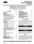
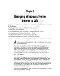
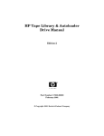
Library Major External Components
Figure 1
1
8
2
7
6
3
5
4
H_65081
1
Optional expansion frame
5
Operator Panel
2
Rear door
6
Optional CAP B (shown closed)
3
Drive access door
7
Standard CAP A (shown open)
4
Right door
8
Left access door
Chapter 1
Tape Library Components
15
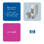
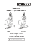
Robot
The robot moves cartridges between storage cells, between cells and tape
drives, and between the CAP and cells. The robot consists of the Z-column
assembly (vertical motion), the theta mechanism (lateral motion), and the
hand-camera assembly. Figure 2 on page 17 shows these robot components.
The Z-column assembly contains a Z-column and Z-carriage. The Z-column
attaches to the floor and ceiling of the tape library. The Z-column can rotate
almost 360 degrees to enable access to all the cells in the tape library.
The hand-camera assembly, which is attached to the Z-carriage, grasps and
releases cartridges. The Z-carriage moves the hand up and down the Z-column
to storage cells, drives, or the CAP.
The camera, which is on the hand, is active only during a library audit. An
audit occurs when you:
■
Power-on the tape library.
■
Open and close the left access library door.
■
Make a request from your backup application software to audit the tape
library.
During an audit, the camera reads the location and volume serial number
(VOLSER) of each cartridge in the storage cells and reserved cells. Since this
information is stored in the library’s memory, the library does not rely on the
camera to read cartridge locations or VOLSERs during mount and dismount
operations.
16
Tape Library Components
Chapter 1
Chapter 1
Figure 2
Robot Components
1
2
3
4
C65114
1
Z-motor
3
Hand-camera assembly
2
Z-column
4
Z-carriage
Chapter 1
Tape Library Components
17
Storage Cells
The library contains storage cells for 228 to 690 cartridges, excluding the CAP
cells. The number of cells is determined by how many drives are installed and
whether the tape library has the standard rear window panel or the expansion
frame. The expansion frame provides additional storage cells for 294
cartridges.
Cell Locations
Cartridges are stored in cell arrays that hold six cartridges. Cell arrays are
stacked in columns and these columns are arranged in a circle around the
robot assembly. Columns can hold up to 42 cartridges.
Table 1 on page 20 lists tape library storage capacities. Figure 3 on page 21
through Figure 4 on page 22 show cell locations for the 20/700 tape library
in its various configurations.
Note
The following statements apply to cell locations:
1. The library uses array targets for robotic calibration during an Initial
Program Load (IPL).
2. Never put data cartridges in the reserved cells (refer to Figure 3 on page
21 for more information). If you do not want to store diagnostic and/or
cleaning tapes in these cells, you must leave them empty.
3. The library does not use the drive and CAP locations to store cartridges.
4. The robot uses the swap cell (the top-most cell in the reserved area) for intransit cartridges, to place a cartridge that is left in the hand-camera
assembly when a power failure occurs, or to perform a swap operation.
18
Tape Library Components
Chapter 1
Chapter 1
Library Capacity
Table 1 on page 20 lists the library storage capacities. Although library
capacity is automatically configured when you bring the library online, check
the operator panel to be sure that the capacity information is accurate.
Note
HP is transitioning the HP Surestore Tape Library Model 20/700
(product number A5597A) to allow for a new feature. This
feature will make it possible to couple two 20/700 libraries
together, allowing tape cartridges to be exchanged between the
libraries. As a result, we are transitioning to a new product
number, A5597B. Until this feature is available and installed, the
display on your library status screen will continue to identify the
library as “A5597A”. In the future, if you choose to use this
feature, your library will then be identified as “A5597B”.
To determine whether your library is an A5597A or A5597B,
refer to the regulatory label on your unit.
Chapter 1
Tape Library Components
19
Table 1
Tape Library Capacity
Expansion Frame
Yes
(Full)
No
(2/3)
No
(1/3)
Second
Drive
Column
Drives Installed
(Maximum)
Panel 2
Access
Total Data
Cartridge
Cells1.
Reserved
Cells2.
No
10 DLT/Ultrium or
6 9840 + 1 DLT or
1 Ultrium
Entire
690
12
Yes
20 DLT/Ultrium or
12 9840 + 2 DLT
or 2 Ultrium
Entire
630
12
No
10 DLT/Ultrium or
6 9840 + 1 DLT or
1 Ultrium
Entire
396
12
Yes
20 DLT/Ultrium or
12 9840 + 2 DLT
or 2 Ultrium
Entire
336
12
No
10 DLT/Ultrium or
6 9840 + 1 DLT or
1 Ultrium
Partial
228
12
Yes
20 DLT/Ultrium or
12 9840 + 2 DLT
or 2 Ultrium
Partial
l68
12
1.
These
These numbers do not include cells in the CAP or the reserved area.
The reserved cells are composed of one swap cell and 11 cleaning and/or diagnostic cartridge slots.
They are shown in Figure 5 on page 25.
2.
The
20
Tape Library Components
Chapter 1
Chapter 1
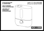
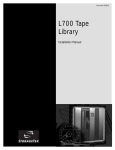
Locating Cartridges - Top View
Figure 3
4
3
2
1
8
7
6
5
1
1/3 capacity (partial access to Panel 2)
5
Drive column 1 (optional)
2
2/3 capacity (entire access to Panel 2)
6
CAP B (optional)
3
Full capacity (with optional expansion frame)
7
CAP A
4
Drive column 0
8
Panel 12
Chapter 1
C65127
Tape Library Components
21
Figure 4
22
Locating Cartridges - Panels, Cells, Rows
Tape Library Components
Chapter 1
1
Chapter 1
Table 2
Locating Cartridges - Panels, Cells, Rows (continued from Figure 4 on
page 22)
228 cartridge cell configuration
4
Optional second CAP
Note: The optional second CAP replaces the
front window.
2
396 cartridge cell configuration
5
Optional second drive column
Note: The optional second drive column
replaces the 60 shaded cells.
3
Expansion frame
Note: 690 cartridge cell configuration
equals 396 cartridge cell configuration
plus an expansion frame.
Chapter 1
Tape Library Components
23
Reserved Cells
Figure 5 on page 25 shows the cells reserved for swapping cartridges and for
diagnostic and cleaning cartridges. The top cell is the swap cell, which is
reserved for in-transit cartridges. Do not place any cartridges into this cell. You
may place any type of cleaning or diagnostic cartridges into the other 11 cells.
24
Note
Loading cleaning cartridges into any of these 11 cells enables
Auto Clean upon the next IPL.
Caution
System degradation: Do not insert data cartridges into these
reserved cells. The host software will not find these cartridges.
Tape Library Components
Chapter 1
Chapter 1
Figure 5
Reserved Cell Locations
CAP B
CAP A
DRIVE
COLUMN 1
1
2
3
C65136
1
Location of reserved cells
2
Swap cell (leave empty)
Chapter 1
3
Diagnostic and cleaning cartridges
Tape Library Components
25
Cartridge Access Port
A cartridge access port (CAP) is the location where you add cartridges to or
remove cartridges from a library without interrupting normal cartridge mounts
and dismounts by the robot. The library may have an optional, second CAP.
Both CAPs are located on the left front door.
The CAP magazine is designed for easy loading. You can access the
magazine by simply pulling down on the magazine handle and adding
cartridges. Or, you can remove the magazine by lifting it out, load the cells,
and place the magazine back into the CAP. Snap-on cartridge retention covers
allow you to keep cartridges in place when transporting magazines.
For detailed procedures, refer to Importing Data Cartridges through the CAP
on page 107 and Library Operation on page 93.
Drives
Note
For drive and media information specific to your drive
technology, refer to Drives and Media on page 143.
The library can contain the following drive types:
26
■
HP Ultrium
■
Digital Linear Tape (DLT) 8000
■
9840
Tape Library Components
Chapter 1
Chapter 1
The maximum number of DLT or Ultrium drives is 20. The maximum number of
9840 drives is 12.
As an operator, you might have to:
■
Configure a drive in a library; refer to Drive Entries on page 76.
■
Check drive status information; refer to Drive Status on page 98.
■
Manually mount a cartridge to a drive or dismount a cartridge from a
drive; refer to Loading/Unloading Cartridges Manually on page 131.
Note
Chapter 1
During typical operation (or automated mode), the library’s
robotic hand-camera assembly automatically places a cartridge
into the drive or removes a cartridge from the drive when a
command is sent from the host software.
Tape Library Components
27
Additional Components
Web-Based Library Administrator (WBLA)
The Web-Based Library Administrator (WBLA) incorporates a web interface to
the library. To use this feature, you will need a personal computer attached to
the library’s Ethernet port. This enables you to:
■
“View” the library interior and visually check the status of tapes, drives,
and CAP
■
Initiate diagnostic tests on the library from the personal computer
■
Make configuration changes or additions
Consult the Web-Based Library Administrator Online Help CD that shipped
with your library for more information.
Tape Library Safety Features
Safety features are incorporated into the tape library. If the left access door is
opened, an electrical interlock removes power from the robot assembly.
Behind the right front door, covers are placed over the logic card, the AC
power supply, and the DC power supply to prevent you from coming into
contact with hazardous voltages and sensitive electronics.
Controlling Software
Controlling software, within the client/server, requests tape read and write
operations to the drives and robotic move operations for the tape library
robotic components. Software determines where the cartridge is located by
tracking the VOLSER and cell location during audits, then allocates which drive
receives the cartridge. For specific information, refer to your software
publications.
28
Additional Components
Chapter 1
Chapter 1
Library Operating Modes
An operating mode is the manner in which a tape library and the controlling
software (also referred to as the customer’s server software) interact. A library
can operate in either automated mode or manual mode.
Automated Mode
Automated mode is the normal operating mode of the tape library. The
controlling software instructs the robot to move the cartridge among the
storage cells, drives, and CAP without operator intervention. Your tasks may
include:
■
Monitoring the tape library operator display for messages
■
Importing a cartridge through the CAP
■
Exporting a cartridge through the CAP
■
Replacing a cleaning cartridge
Refer to Library Operation on page 93 for the procedures.
Manual Mode
Manual mode refers to the tape library being inactive. Your tasks may include:
■
Opening the tape library doors
■
Moving the robot
■
Locating a cartridge
■
Removing a cartridge from the hand
■
Mounting a cartridge into a drive
■
Dismounting a cartridge from a drive
Refer to Library Operation on page 93 for the procedures.
Chapter 1
Library Operating Modes
29
Auto Clean Feature
Note
Ensure your backup software supports this feature before
enabling.
Drives occasionally need to be cleaned to prevent read/write errors.
The Auto Clean feature is enabled when your tape library is initializing and
detects cleaning cartridges in the reserved cells. When a drive requires
cleaning while Auto Clean is enabled, the robot will receive a software
message telling it to retrieve a cleaning cartridge and place it into the drive.
If Auto Clean is not enabled, you must manually import a cleaning cartridge
for the drive that requires cleaning. The Clean Drive request appears on the
operator panel’s display.
Refer to For cleaning cartridge information specific to your drive type, see
Drives and Media on page 135. on page 88 for more information and
procedures.
Note
30
Auto Clean Feature
For cleaning cartridge information specific to your drive
technology, see Drives and Media on page 143.
Chapter 1
Chapter 1
Accessory Bin
You may use the internal 13U (0.57 m [22.75 in.] x 0.48 m [19 in.]) accessory
bin, located in the rack behind the right front door, for additional equipment.
Refer to Rack Safety and Precautions on page 199 for precautions you must
follow before installing equipment in this area.
Power cable space is provided in the cutout area of the rear door.
Note
Chapter 1
Heat within rack area: Cooling considerations should be made
based upon the power dissipation within the rack space, as well
as the external library room ambient conditions. Cooling must
be provided for moderate power dissipation within the rack
space.
Accessory Bin
31
32
Accessory Bin
Chapter 1
Controls and Indicators
2
This chapter describes the functions of the library operator panel, the library
power switch, and provides samples of displays you could see on the operator
panel display. It also lists tasks you can perform through the use of the
operator panel.
33
Operator Panel
The operator panel, recessed into the library’s rack door, contains buttons,
indicators, and a graphic display. Figure 6 on page 36 shows the panel and
Table 3 on page 37 describes each item.
34
Operator Panel
Chapter 2
Use the operator panel to:
Monitor current information about the CAPs, configuration, drives, doors,
drive cleaning, hardware and software versions, personality, and library
status
■
Help resolve library problems
■
If an error occurs, the display shows a fault symptom code (FSC), which
you can give to a service representative to help resolve problems. Write
down the FSC as soon as it is displayed.
■
Set library, network, and drive configurations
■
Rotate the CAPs
■
Replace drive cleaning cartridges and set cleaning cartridge warning
count
■
Run library and drive tests
■
Reset the library (start an initial program load [IPL])
For specific task instructions, refer to Configuration on page 65 and Library
Operation on page 93.
Chapter 2
Operator Panel
35
Chapter 2
■
Operator Panel Display, Controls, and Indicators
Figure 6
11
1
10
2
3
9
LIBRARY
ACTIVE
SERVICE
REQUIRED
OPEN
OPEN
MENU
A
CAP
SELECT
B
CAP
RESET
4
5
6
7
8
C65083
36
Operator Panel
Chapter 2
Table 3
Operator Panel Display, Controls, and Indicators (continued from
Figure 6 on page 36)
Service Required indicator is steadily red
when human intervention is required.
7
[RESET] button, located behind the right front
door, starts an IPL.
2
Library Active indicator flashes green when
the library is operational.
8
Arrow down button moves the cursor down
the display screen or decrements an
underscored value.
3
Open indicator is steadily amber when the
CAP is open for you to import or remove
cartridges.
9
[SELECT] button selects an item on a menu; it
also saves the currently underscored value
and moves the cursor to the next field.
4
[CAP A] open button rotates CAP A for you
to access the magazines.
10
Arrow up button moves the cursor up the
display screen; it also increments a value
underscored on the screen.
5
[CAP B] open button rotates CAP B for you
to access the magazines.
11
Graphic display screen shows current
information, FSCs, and allows input from
menus.
6
[MENU] button initially places you into the
Main Menu screen; subsequently, it returns
you to a previously selected screen.
Chapter 2
Operator Panel
37
Chapter 2
1
Indicators
Three indicators provide basic status information: Library Active, Service
Required, and Open. Refer to Table 3 on page 37 for details about these
indicators.
Note
When the Service Required indicator is on, contact your service
provider.
Buttons
Seven buttons are provided on the operator panel: [CAP A], [CAP B], [RESET],
[MENU], [SELECT], and the up and down arrows. The [CAP] and [RESET]
buttons let you directly manipulate the library; the remaining four buttons let
you manipulate the menus and underscored values on the graphic display.
Refer to Figure 6 on page 36 and Table 3 on page 37 for the location and a
description of each button.
Note
38
Operator Panel
The up arrow, down arrow, [MENU] and [SELECT] buttons
manipulate only values that are under operator control. As you
scroll down or up a list of selections, the cursor underscores these
values. (You cannot manipulate values that do not permit
underscoring.)
Chapter 2
Display Screens
■
Drive status
■
CAP and CAP magazine status
■
Library status
■
Library capacity
■
Library personality
■
Library features
■
Hardware and software versions
■
SCSI type (single-ended or differential)
■
Cleaning cartridge and Auto Clean status
■
Ethernet ID
■
Error and FSC information
Note
HP is transitioning the HP Surestore Tape Library Model 20/700
(product number A5597A) to allow for a new feature. This
feature will make it possible to couple two 20/700 libraries
together, allowing tape cartridges to be exchanged between the
libraries. As a result, we are transitioning to a new product
number, A5597B. Until this feature is available and installed, the
display on your library status screen will continue to identify the
library as “A5597A”. In the future, if you choose to use this
feature, your library will then be identified as “A5597B”.
To determine whether your library is an A5597A or A5597B,
refer to the regulatory label on your unit.
Chapter 2
Operator Panel
39
Chapter 2
Screens on the graphic display show current information and allow your input.
Information includes:
Except for CAP status and error or FSC information, these values are set
through an automatic configuration process that occurs during an IPL.
Values requiring your input are:
■
Cleaning cartridge warning count
■
SCSI drive configuration:
— SCSI ID
— Bus status (on or off bus)
■
Network configuration:
— Library name
— IP address
— Subnet mask
— Library gateway
■
Library configuration information:
— SCSI ID
— Fast Load enable/disable
— Date/time
■
Display screen brightness and contrast
You can also use the menus to run diagnostic tests.
The following pages describe the library’s primary menus. For instructions on
working with specific configuration values, see Operator Panel Entry on
page 70.
40
Operator Panel
Chapter 2
Library Status
HP A5597A (CODE VERSION
X.XX.XX)
Library type and firmware version
CAP (A) CLOSED
CAP status
LIBRARY READY
Library status
WEB ENABLED
Remote access is available through the
Web-Based Library Administrator
(WBLA)
COLUMN 0
The status of each drive in a specified
drive column
Figure 7 on page 41 shows an example Library Status screen. (For a list of
drive status messages, see Drive Status on page 98.)
Figure 7
Library Initial Status Screen
HP A5597A(CODE VER X.XX.XX)*
CAP CLOSED
LIBRARY READY
WEB ENABLED
COLUMN 0
00 BUSY
01 BUSY
02 LOADING
03 LOADING
04 EMPTY
05 EMPTY
06 EMPTY
07 --08 --09 ---
Chapter 2
Operator Panel
41
Chapter 2
The Library Status screen is an information-only screen. It is the first screen to
appear on the operator panel after an IPL.
Note
With 3.00 firmware and higher, an asterisk (*) may appear on
the operator panel display. For example, HP A5597A (Code
3.00.xx)*. The asterisk (*) denotes the cleaning cartridge’s life
has expired. To determine which cartridge has expired and to
eject the expired cartridge, see For cleaning cartridge
information specific to your drive type, see Drives and Media
on page 135. on page 88, and Exporting Data Cartridges
through the CAP on page 112.
By pressing the [MENU] button from the Library Status screen, you can display
the Main Menu (see Figure 8 on page 42).
Figure 8
Main Menu Screen
MAIN MENU:
FSC LOG
CAP CONTENTS
DRIVE INFO
CLEANING INFO
DIAGNOSTICS
VERSION INFO
CONFIGURATION
42
Operator Panel
Chapter 2
FSC (Fault Symptom Code) Logs
Note
Figure 9
Events listed in the log might not be failures. All events are
recorded. FSCs are generated for both library and drive errors.
FSC Log Screen
.
3329
03
03/01/2001
3304
09
03/01/2001
30BB
02
03/01/2001
30BA
02
03/01/2001
30B9
02
02/28/2001
30B8
02
02/28/2001
4487
02
02/27/2001
3329
03
Chapter 2
Chapter 2
The FSC Logs screen displays the last 20 fault symptom codes (FSCs), the
number of occurrences, and the date and time of the last occurrence. The
screen may be scrolled (if required) to view all FSCs. For more information,
Reviewing FSC Logs on page 114.
DRIVE_00_00
14:46:14
DRIVE_01_00
14:46:14
NONE
14:44:01
NONE
14:44:01
DRIVE_02_00
09:22:23
NONE
08:27:14
NONE
16:52:33
NONE
Operator Panel
43
CAP Contents
The CAP Contents screen is an information-only screen. It displays either the
VOLSER of a cartridge or status message for each slot in a CAP magazine.
The CAP status screen is shown in Figure 10 on page 44.
Note
Figure 10
You must scroll down to view the contents of both CAPs.
CAP Status Screen
CAP A CONTENTS
MAGAZINE 1 CONTENTS
200042
57QF43R
EMPTY
EMPTY
EMPTY
MAGAZINE 2 CONTENTS
EMPTY
EMPTY
EMPTY
EMPTY
EMPTY
44
Operator Panel
Chapter 2
Drive Information
VENDOR
The manufacturer of the drive
TYPE
The drive model
STATUS
The drive’s local number and status (see Drive
Status on page 98 for a list of status messages)
SERIAL NUMBER
The serial number assigned by the drive’s
manufacturer
INTERFACE TYPE
The type of client-to-drive interface (a SCSI
interface)
CODE VERSION
The firmware version of the drive
Note
Figure 11
See Drive Information on page 99 for instructions on how to
access a drive. For information specific to your drive technology,
including troubleshooting, see Drives and Media on page 143.
Drive Information Menu
DRIVE INFORMATION MENU:
VENDOR: HP
TYPE: HP LTO
STATUS: 00 EMPTY
SERIAL NUMBER:
XXXXXXXXXX
INTERFACE TYPE:
SCSI I/F
CODE VERSION
X.XX.XX
Chapter 2
Operator Panel
45
Chapter 2
The Drive Information menu is an information-only screen that lists
manufacturing and status information about the selected drive (see Figure 11
on page 45):
Cleaning Information
The Cleaning Info menu provides information about and control of the
library’s cleaning cartridges. It enables you to change the warning count for
each type of cleaning cartridge. Figure 12 on page 47 shows an example of
the Cleaning Info menu:
NUM CLEAN
CARTRIDGES
The total number of cleaning cartridges
mounted in the reserved cells within the library
DLT WARN COUNT
The number times you want the DLT cleaning
cartridge to be used before the library exports
it through the CAP (20 uses)
9840 WARN COUNT
The number times you want the 9840 cleaning
cartridge to be used before the library exports
it through the CAP (100 uses)
HP LTO WARN COUNT
The number of times you want the Ultrium
cleaning cartridge to be used before the
library exports it through the CAP (15 uses)
Note: The Ultrium universal cleaning cartridge
has a maximum of 50 uses.
EXPORT
CARTRIDGES
A procedure for moving cleaning cartridges
from the reserved cells to the CAP
IMPORT
CARTRIDGES
A procedure for moving cleaning cartridges
from the CAP to the reserved cells
CLEAN CARTRIDGE INFO
A path to an information screen that lists all
cleaning cartridges in the library
The Cleaning Info menu lets you change the warning count for each type of
cleaning cartridge and import/export cleaning cartridges. It also lets you
check the number of times a cleaning cartridge has been used. For
procedures, see Library Operation on page 93.
46
Operator Panel
Chapter 2
Figure 12
Cleaning Information Menu
Chapter 2
CLEANING INFO MENU:
NUM CLEAN CARTRIDGES: 00
DLT WARN COUNT: 000
9840 WARN COUNT: 000
HP LTO WARN COUNT: 000
EXPORT CARTRIDGES
IMPORT CARTRIDGES
CLEAN CARTIDGE INFO
Chapter 2
Operator Panel
47
Diagnostic Tests
Note
Additional diagnostics are available from HP Library & Tape
Tools (see HP Library & Tape Tools on page 146 for more
information). Also, for troubleshooting information specific to
your drive technology, see Drives and Media on page 143.
All Diagnostic tests except for Clean Drive require the tape library and
associated drive to be inactive. The Main Diagnostics Menu (see Figure 13 on
page 49) lets you perform the following tests:
■
DRIVE DIAGNOSTICS:
— CLEAN DRIVE. Enables you to clean tape drives.
— MOUNT. Loads test tapes to a drive.
— DISMOUNT. Unloads test tapes from a drive.
— RUN DRIVE CHECK. Determines that the drive is in working order.
— MOUNT/DISMOUNT LOOP. Loads and unloads test tapes from a
drive. You may designate the number of times the tape library goes
through the loop.
Note
HP does not recommend looping tests excessively.
■
GET-PUT LOOP. Gets a diagnostic tape and returns it to the same location.
You may designate the number of times the tape library goes through the
loop.
■
DEMO MODE. Simulates tape library operation.
For more information on using these tests, see Running Diagnostic Tests on
page 115.
48
Operator Panel
Chapter 2
Figure 13
Main Diagnostics Menu
Chapter 2
MAIN DIAGNOSTICS MENU:
DRIVE DIAGNOSTICS
GET/PUT LOOP
DEMO MODE
Version Information
The Version Info Menu is an information-only screen (see example in Figure
14 on page 49). It displays the version level of the library’s functional code,
the date the code was completed, and the serial number of the logic card (also
referred to as “the MPC card”).
Figure 14
Version Information Menu
VERSION INFO MENU:
HP A5997A
CODE VERSION:
X.XX.XX
CODE BUILT ON:
(MONTH DAY YEAR TIME)
HARDWARE / VERSION
MPC XXXXXXXX
Chapter 2
Operator Panel
49
Configuration Menu
The Main Configuration Menu (see Figure 15 on page 50) allows you access
to the configuration menus (library, drive, network) and to the panel display
controls. You can access screens that let you view the library personality,
perform a feature upgrade, and input a password for a Web interface
product.
Figure 15
Configuration Menu
CONFIGURATION MENU
LIBRARY CONFIG
DRIVE CONFIG
NETWORK CONFIG
PERSONALITY MODULE
WEB PASSWORD
DISPLAY INFO
50
Operator Panel
Chapter 2
Library Configuration
The screen displays:
LIB SCSI I/F CONFIG
Library interface identifier
FAST LOAD
Fast Load feature status (on or off)
DATE
Current date
TIME
Current time
AUTO CLEAN
Is Auto Clean enabled?
USER CELLS
Number of data storage cells in the library
CAPS
Number of CAPs installed
DRIVE COLUMN
Number of drive columns installed
EXPANSION FRAME
Is an expansion frame installed?
Figure 16 on page 51 shows an example library configuration screen. From
this menu, you may access editing menus for these library settings. See Library
Entries on page 70 for procedures and additional information.
Figure 16
Library Configuration Menu
LIB CONFIG MENU:
LIB SCSI I/F CONFIG
FAST LOAD: OFF
DATE: 03/01/2001
TIME: 23:59
AUTO CLEAN: OFF
USER CELLS: 336
CAPS: 2
DRIVE COLUMN: 2
EXPANSION FRAME: NO
Chapter 2
Operator Panel
51
Chapter 2
The Lib Config Menu displays library capacity information and lets you modify
the library’s configuration.
Library SCSI Interface Configuration
The Lib SCSI I/F Config Menu lets you view the library’s SCSI type (differential
or single-ended) and access an edit menu for the library’s SCSI ID. Figure 17
on page 52 shows an example of this menu.
Figure 17
Library SCSI Interface Configuration Menu
LIB SCSI I/F CONFIG MENU:
SCSI ID: 00
SCSI TYPE: SE/LVD
52
Operator Panel
Chapter 2
Drive Configuration
■
Drive position
■
Drive type
■
If the drive path is SCSI, the drive’s SCSI ID and its SCSI bus relationship
with the library.
Sub-menus let you change the SCSI ID and configure whether the drive is on
the same SCSI bus as the library. For more information, see Drive Entries on
page 76.
Note
The cursor position is saved on all screens that list the library’s
drives.
The panel displays 16 lines of data per menu. If your library
contains more than eight drives, you must use the down arrow
button to scroll to drives 08 and above.
Figure 18
Drive Configuration Menu
SET DRIVE SCSI ID MENU:
01 HP LTO ID: 02
VALID RANGE 0 - 15
SCROLL UP TO INCR
SCROLL DOWN TO DECR
SELECT TO SAVE
MENU TO EXIT
Chapter 2
Operator Panel
53
Chapter 2
The Drive Config Menu lets you modify each drive’s configuration. Figure 18
on page 53 shows an example screen. For each drive, the menu displays:
Network Configuration
The Network Config Menu (see Figure 19 on page 54) lets you modify the
library’s network configuration and view the library’s Ethernet (web interface)
address. (At the time of publication, you cannot change the DHCP status.) For
procedures, see Network Entries on page 79.
Figure 19
Network Configuration Menu
NETWORK CONFIG MENU:
LIBRARY NAME:
_
IP ADDRESS:
000.000.000.000
NETWORK GATEWAY:
000.000.000.000
SUBNET MASK:
000.000.000.000
DNS CONFIGURATION
DMN
SVR PRIMARY
SVR SECONDARY
DHCP: DISABLED
ETHERNET ADDRESS:
00:10:4F:00:05:76
54
Operator Panel
Chapter 2
Personality Module
Note
Figure 20
In the Personality Module menu, “HORIZON” refers to web
access and indicates whether or not it is enabled.
Personality Module Information
PERSONALITY MODULE INFO:
STATUS:
PRESENT
TYPE:
NORMAL
VERSION:
0
LIBRARY VENDOR ID:
1
LIBRARY VENDOR NAME:
HP
LIBRARY PRODUCT TYPE:
A5597A
HORIZON:
ENABLED
SCSI VENDOR NAME:
HP
SCSI PRODUCT NAME:
A5597A
Chapter 2
Operator Panel
55
Chapter 2
The Personality Module menu lets you view the library’s personality (vendor)
setting. The expanded screen in Figure 20 on page 55 illustrates how you can
check the Personality Module.
Web Password
The Web Password menu item allows you to view or change your password.
See Figure 21 on page 56.
Figure 21
Web Password
WEB PASSWORD:
XXXXXXX
USE ARROWS TO CHANGE
EACH LETTER
SELECT TO MOVE RIGHT
SELECT ON SPACE TO
SAVE THE PASSWORD
MENU TO MOVE LEFT
OR TO EXIT
Display Information
The Display Info Menu (see Figure 22 on page 56) leads to menus that let you
adjust the contrast and backlight on the graphic display screen. For more
information, see Screen Characteristics on page 87.
Figure 22
Display Information Menu
DISPLAY INFO MENU:
CONTRAST: 09
DEFAULT = 16
BACKLIGHT: 128
DEFAULT = 128
RESTORE DEFAULTS
MENU TO EXIT
56
Operator Panel
Chapter 2
Operations Overview
Chapter 2
■
FSC LOGS
■
CAP CONTENTS
■
DRIVE INFO
■
CLEANING INFO
■
DIAGNOSTICS
■
VERSION INFO
■
CONFIGURATION
Operator Panel
57
Chapter 2
Table 4 on page 58 lists the tasks that you can perform through the operator
panel menus. The right column refers you to another page in this manual for
more information. The options from the Main Menu include:
Table 4
Operations Guide
Task
Page for Operator Panel Instructions
Understand CAP status messages
page 96
Understand library status messages
page 97
Understand drive status messages
page 98
Review FSC logs
page 114
Check CAP magazine
page 99
Manage cleaning cartridges
See list for individual tasks.
■
Import cleaning cartridges through CAP
page 105
■
Export cleaning cartridges to CAP
page 104
■
Check usage count
page 101
■
Check/set warning count
page 88
■
Manually clean a drive
page 112
■
Import data cartridges through CAP
page 107
■
Export data cartridges through CAP
page 112
Run diagnostic tests
page 115
■
Run get/put loop
page 117
■
Operate in demo mode
page 118
■
Run drive mount diagnostics
page 116
Check firmware version
page 49
Check library personality information
page 102
Set configuration
page 70
■
Set library SCSI ID
page 71
■
Enable/disable Fast Load
page 73
58
Operator Panel
Chapter 2
Table 4
Operations Guide
Page for Operator Panel Instructions
■
Set date and time
page 74
■
Set drive configuration
page 76
■
Set network configuration
page 79
■
Set screen characteristics
page 87
Chapter 2
Operator Panel
Chapter 2
Task
59
Library Power Switch
Note
Be aware that each PDU supplies power to the robotics and half
of the drives. When the library has two PDUs (and a drive
column with two power cords), each PDU is connected to
separate branch AC circuit.
If you are installing multiple drives in the library (and the library
is a newer model with two power cords to the drive column), HP
recommends that you configure some drives in the upper five
slots, and some drives in the lower five slots in the drive column.
With this configuration, if one PDU loses power, some drives and
the library robotics will remain operational.
The library power switch is a circuit breaker or breakers behind the right front
door of the library. Figure 23 on page 62 shows the power switch location.
This switch, attached to the AC power distribution unit (PDU), controls the AC
power to the library and drive column.
The power switch has two configurations:
■
A single breaker on the AC power distribution unit controls the library and
a single drive column.
■
A second breaker, located on the second power distribution unit, powers
the second drive column and an optional second library power supply.
Note
Your library has two circuit breakers:
The second PDU must be connected to a separate electrical
circuit.
If only one breaker is powered off, the second breaker will still
be powered on.
60
Library Power Switch
Chapter 2
To apply power to the library and drive column, lift the switch or switches.
■
Make sure all jobs are complete.
■
Push down on the library power switch or switches.
Note
Chapter 2
Chapter 2
To remove power from the library and drive column:
The arrow in Figure 23 on page 62 shows moving the power
switch to the on position.
Library Power Switch
61
Figure 23
62
Library Power Switch
Library Power Switch Location
Chapter 2
The tape drives are behind the drive access door, inside the right side door of
the library. Each drive has a power switch that controls the power to only that
drive.
Note
The library’s main power switch controls the AC power to the
library and the drive column.
■
To remove power from a drive, push the drive switch to the “O” position.
■
To supply power to a drive, push the drive switch to the “|” position
Drive Power Switch Locations
Figure 24
1
2
C65131
1 DLT or Ultrium drive power switch
Chapter 2
2 9840 drive power switch
Tape Drive Power Switches
63
Chapter 2
Tape Drive Power Switches
64
Tape Drive Power Switches
Chapter 2
3
Configuration
This chapter describes how to configure the library and drives for operation.
Configuration requires you to:
1. Enable Auto Clean (if desired) by installing cleaning cartridges
2. Power on or reset the library
3. Enter library and drive configuration information
4. Send a client command to load library audit information into client
memory
After power-on, the library automatically verifies and loads some configuration
values, such as drive locations, Auto Clean status, capacity, and drive types.
Before the library is fully operational, however, someone must enter the
remaining configuration values.
Typically, your service representative will configure your library during
installation, during firmware upgrade, or after drives are added. If you must
change the library’s configuration, you may enter the values through the
operator panel.
Note
You may need to consult with your systems administrator for
some information.
65
Enabling Auto Clean
Note
Ensure your backup software support this feature before
installing. For cleaning cartridge information specific to your
drive type, see Drives and Media on page 135.
You will need to clean the drives occasionally to prevent read and write errors.
Enabling the Auto Clean feature allows the library to initiate drive cleaning
without your intervention. (A drive is cleaned with a special cleaning
cartridge.)
To enable Auto Clean, load valid cleaning cartridges into any of the 11 cells
that are reserved for cleaning and diagnostic cartridges. For the locations of
these cells, refer to Reserved Cells on page 24.
Note
To be valid:
A cleaning cartridge must have “CLN” in its VOLSER label.
9840 cleaning cartridges must also have a “U” on their media
ID labels.
HP Ultrium cartridges have unique bar code labels specific to HP
as the drive manufacturer. For more information, see Drives and
Media on page 143.
66
Enabling Auto Clean
Chapter 3
The Auto Clean feature is automatically enabled if you load even one cleaning
cartridge into the reserved cell area and then reset the library.
For instructions on how to use the CAP to insert cleaning cartridges, see
Importing Cleaning Cartridges through the CAP on page 105. For the
location of the reserved cells, see Reserved Cells on page 24.
To install cleaning cartridges in the reserved cells:
2. Verify that the cleaning cartridges are right side up (the VOLSER numbers
should be closest to the top edge and facing outward).
Caution
Potential static electricity damage to electrical components. Take
precautions against electrostatic discharge by touching gray,
unpainted metal (such as the library’s frame) before reaching
into the library. Avoid touching any electrical component.
3. Place a cartridge into any of the 11 designated cells.
4. Close and lock the front access door.
Note
Chapter 3
You may follow this same procedure to load diagnostic
cartridges into the reserved cells. (Every diagnostic cartridge has
“DG” as the first two letters of its VOLSER.) However, loading
diagnostic cartridges alone does not enable Auto Clean.
Enabling Auto Clean
67
Chapter 3
1. Unlock and open the front doors (see Opening the Library Front Doors on
page 122).
Powering on the Library
Powering on the library supplies power to the library electronics and to the
drive column. If you have a second drive column, you must power on both
supplies. Powering on also initiates an IPL of the library.
To power on the library, lift the switch (circuit breaker) or switches behind the
right front door of the library. If you are not familiar with the location of the
switches, refer to Figure 23 on page 62.
Note
68
Powering on the Library
If the tape library does not power on, contact your service
provider.
Chapter 3
Initializing and Resetting the Library
Re-initializing the Library
You will have to re-initialize the library in the rare instance when a robotic
component malfunctions. Before re-initializing the library, perform any
necessary manual operation tasks (see Manual Operation on page 121).
To re-initialize the library, make sure that all drives are powered on and
perform one of these actions:
■
Power off and power on the library (also causes an IPL)
■
Open and close the front door
Resetting the Library
You will have to reset the library when:
■
You are directed to do so by your system administrator or a service
representative
■
You have to change the library configuration (for example, when you have
to change the library’s SCSI ID)
To reset the library after it is already powered on, make sure that all the drives
are powered on and press the [RESET] button on the operator panel.
Chapter 3
Initializing and Resetting the Library
69
Chapter 3
Powering on the library causes it to initialize components and perform an
Initial Program Load (IPL). During initialization, the library prepares the robot
for operation and audits any cartridges in the storage and reserved cells.
During an IPL, the library loads the operating code and automatically verifies
some configuration values, such as drive locations and drive types.
Entering Configuration Data
After the IPL is complete, the status screen will appear on the operator panel.
At this point, you must make choices about your library, drives, and network
and enter those choices into the library’s memory.
Note
You may need to consult with your systems administrator for
some information.
You may enter all configuration data through the operator panel. See
Operator Panel Entry (in the following section) for specific instructions. Using
the Web-Based Library Administrator, you also can enter some configuration
data through a workstation or a PC that is running a Netscape or Microsoft
browser. For more information, access the online help files for the Web-Based
Library Administrator. They are available from the CD-ROM that shipped with
your product, or you can download them from www.hp.com/go/support.
Operator Panel Entry
Entering configuration data through the operator panel prepares the library
for operation. For a detailed description of the operator panel, see Operator
Panel on page 34.
Library Entries
Four entries are required for a library—other entries will vary with your
options:
70
■
Library SCSI ID
■
Drive Fast Load enable/disable
■
Date
■
Time
Entering Configuration Data
Chapter 3
Note
The following procedures assume that you will make all entries
during one operator panel entry session. Each item is saved as it
is changed, except for the library’s SCSI ID: to save a revised
library SCSI ID, you must reset the library by pressing the
[RESET] button.
If the control path for the library is SCSI, you must enter the library’s SCSI ID at
the operator panel. Set the library SCSI ID from the Lib SCSI I/F Config menu.
Note
■
The information below explains special circumstances for
selecting a SCSI ID (address) for the library:
When configuring the library to a Unix-based workstation, HP
recommends that you use a dedicated SCSI client host bus adapter (HBA):
— For wide SCSI adapters, you may assign any address from 0 to 14 for
the library.
— For narrow SCSI adapters, the range of addresses is 0 to 6.
■
If you choose to use the embedded system bus on the SPARC station, select
address 6, 5, 2, or 0 for the library; the remaining targets are reserved for
Sun peripherals.
■
For RISC System/6000 machines, available addresses on the embedded
system bus are 6, 5, 3, and 2.
To set the library’s SCSI ID:
1. From the online status screen, press the [MENU] button.
The Main Menu will display.
2. Press the down arrow button until the cursor underscores
CONFIGURATION.
3. Press the [SELECT] button.
The main Configuration Menu will appear and the cursor will line up with
LIBRARY CONFIG.
Chapter 3
Entering Configuration Data
71
Chapter 3
Setting the Library’s SCSI ID
4. Press the [SELECT] button.
The Lib Config Menu will appear and the cursor will line up with LIB SCSI
I/F CONFIG.
5. Press the [SELECT] button.
The Lib SCSI I/F Config Menu will appear. (This menu also displays the
type of SCSI interface: differential or single-ended.)
6. Press the arrow buttons until the cursor underscores SCSI ID.
7.
Press the [SELECT] button.
The Set Lib SCSI ID Menu will appear.
8. Press the up and down arrow buttons to select the correct ID.
9.
Press the [SELECT] button to save the changes. (You may press the [MENU]
button to abort.)
10. If the library SCSI ID is the only configuration value you wish to set at this
time, press the [RESET] button. If you wish to set other configuration values
before you reset the library, continue with the next section.
72
Entering Configuration Data
Chapter 3
Enabling/Disabling Fast Load
These two terms are defined as follows:
The robot will mount a tape to a drive and then
immediately report the move completed.
Fast load off:
The robot will mount a tape to a drive and wait at the
drive location until the tape is completely loaded before
reporting the move completed.
Note
Some host software does not support the fast load enabled
option.
Enable or disable the Fast Load feature from the Lib Config Menu. To set either
feature:
1. At the Lib Config Menu screen, press the arrow button until the cursor
underscores FAST LOAD.
2. Press the [SELECT] button.
An editing screen appears.
3. Press the up and down arrow buttons to select either ON or OFF.
4. Press the [SELECT] button to save the changes. (You may press the [MENU]
button to abort.)
5. If you have already changed the library’s SCSI ID and are planning to exit
the main Configuration Menu at this time, you must press the [RESET]
button. If you want to set other configuration values, continue with the next
section.
If you have not changed the library’s SCSI ID and are not setting other
configuration values, press the [MENU] button until you exit all menus.
Chapter 3
Entering Configuration Data
73
Chapter 3
Fast load on:
Setting the Date
Set the date and time from the Lib Config Menu:
1. At the Lib Config Menu screen, press the arrow button until the cursor
underscores DATE.
2. Press the [SELECT] button.
An editing screen appears.
3. On the editing screen:
a. Press the up and down arrow buttons to select a value for each
portion (field) of the date.
b. Press the [SELECT] button to move right to the next field.
c.
Press the [MENU] button to move left to the previous field.
4. When the screen displays your desired setting, press the [SELECT] button
from the right-most field to save the changes. You may press the [MENU]
button from the left-most field to abort.
5. If you have already changed the library’s SCSI ID and are planning to exit
the main Configuration Menu at this time, you must press the [RESET]
button. If you wish to set other configuration values, continue with the next
section.
6. If you have not changed the library’s SCSI ID and are not setting other
configuration values, press the [MENU] button until you exit all menus.
Setting the Time
Set the time from the Lib Config Menu. FSC log entries correspond to this time
setting:
1. At the Lib Config Menu screen, press the arrow button until the cursor
underscores TIME.
2. Press the [SELECT] button.
An editing screen appears.
3. On the editing screen:
a. Press the up and down arrows to select a value for each portion (field)
of the time.
b. Press the [SELECT] button to move right to the next field.
c.
74
Entering Configuration Data
Press the [MENU] button to move left to the previous field.
Chapter 3
4. When the screen displays your desired setting, press the [SELECT] button
from the right-most field to save the changes. (You may press the [MENU]
button from the left-most field to abort.)
5. If you have already changed the library’s SCSI ID and are planning to exit
the main Configuration Menu at this time, you must press the [RESET]
button. If you wish to set other configuration values, continue with the next
section.
Chapter 3
6. If you have not changed the library’s SCSI ID and are not setting other
configuration values, press the [MENU] button until you exit all menus.
Setting the Web Password
If your library uses the Web-Based Library Administrator, you must set a Web
password at the operator panel. For instructions on setting this value, see Web
Password on page 56 and the Web-Based Library Administrator Online Help
CD that shipped with your library.
Chapter 3
Entering Configuration Data
75
Drive Entries
Note
For 9840 drives only:
The drive’s SCSI ID and bus status can be entered from the
library’s operator panel if the drive has firmware version 1.24 or
higher. Check the drive’s firmware version, by selecting DRIVE
INFO from the Main Menu.
Configuring a 9840 drive might involve more than setting the
drive’s SCSI ID and bus status. For more information about 9840
drive configuration options and instructions, refer to the 9840
Tape Drive Service Manual.
Two entries complete the configuration options for each SCSI drive:
■
SCSI ID
■
Bus status (on or off bus)
Note
“On Bus” means that the drive is on the same SCSI bus as the
library. “Off Bus” means that the drive is not on the same SCSI
bus as the library.
Set the drive SCSI IDs and bus status from the drive configuration menu. You
can enter both values for each drive at the same time:
1. At the main Configuration Menu, press an arrow button until the cursor
underscores DRIVE CONFIG.
2. Press the [SELECT] button.
The screen will list all installed drives, and the cursor will align with the first
drive on the list.
An example of the format is:
00 HP LTO ID: 01
ON BUS: ON
The first two digits are the drive’s logical number (the number that the
library has assigned the drive). The tape library sets this number during its
automatic configuration sequence (at power-on or reset). It is an internal
number only and is shown for information only.
76
Entering Configuration Data
Chapter 3
Note
The uppermost drive within the column is designated as “0,” the
next is “1,” and so forth.
Next to the logical number is the drive type (DLT 8000 in this example). To
the right of the drive type is the ID or SCSI address. On the next line is the
drive’s bus status.
Chapter 3
Ultrium drives will display as:
— HP LTO for Hewlett Packard Ultrium drives
Drive information might also appear on the menu as:
— INVALID if the drive’s SCSI ID is an invalid address
3. Press the arrow buttons to scroll to the drive you wish to change and press
the [SELECT] button.
The Set Drive SCSI ID Menu will appear.
Note
The operator panel displays only 16 lines per menu. If the
library contains more than eight drives, you must use the down
arrow button to scroll to drives 09 and above.
4. Press the up and down arrow buttons to change the ID.
5. Press [SELECT] to save your changes.
A message screen will appear to indicate that the library is saving the new
ID. Then the Drive Config Menu will reappear.
Note
The new SCSI ID for a 9840 drive might not appear right away.
6. Press the arrow down button to get to the drive’s second line of
information (the drive’s bus status field).
7.
Press the [SELECT] button.
The Set Drive SCSI Bus Menu will appear.
8. Press the up and down arrow buttons to change the bus status to ON or
OFF.
Chapter 3
Entering Configuration Data
77
9.
Press the [SELECT] button to save the changes. (You may press the [MENU]
button to abort.)
The drive configuration screen will reappear.
10. Continue these steps until all drives are configured.
11. If you have already changed the library’s SCSI ID and are planning to exit
the main Configuration Menu at this time, you must press the [RESET]
button. If you wish to set other configuration values, continue with the next
section.
12. If you have not changed the library’s SCSI ID and are not setting other
configuration values, press the [MENU] button until you exit all menus.
78
Entering Configuration Data
Chapter 3
Network Entries
You may set the library’s network configuration, and view the library’s Ethernet
address from the Network Config Menu.
Note
You may need to consult with the systems administrator for some
information.
Chapter 3
The following entries set the library’s network configuration:
■
Library name
■
IP address
■
Network gateway
■
Subnet mask
■
Domain Name Service (DNS) Configuration
Note
Domain Name Service (DNS) Configuration: You must enter the
(DNS) configuration only if your Simplified Network
Management Protocol (SNMP) agent is set to collect ("trap")
named recipients. If SNMP is set for numbered recipients, no
entries are required (see DNS Configuration on page 85).
You also may view the library’s Ethernet address.
Chapter 3
Entering Configuration Data
79
Viewing the Ethernet Address
This is a six-byte address, unique to each library. The address is written into
the MPC card at the factory and cannot be changed. An example of an
Ethernet address is 00:10:4f:00:05:01.
To view the Ethernet address:
1. At the Main Configuration Menu, press the arrow down button to line up
the cursor with NETWORK CONFIG.
2. Press the [SELECT] button.
The Network Config Menu will appear and the library’s Ethernet address
appears at the bottom of the screen.
3. If you have already changed the library’s SCSI ID and are planning to exit
the main Configuration Menu at this time, you must press the [RESET]
button. If you wish to set other configuration values, continue with the next
section.
If you have not changed the library’s SCSI ID and are not setting other
configuration values, press the [MENU] button until you exit all menus.
80
Entering Configuration Data
Chapter 3
Setting the Library Name
The system administrator might assign the library a name. The name is
mapped to the IP address but does not affect operation. To set the library
name:
1. At the Network Config menu, press an arrow button until the cursor
underscores LIBRARY NAME.
Chapter 3
2. Press the [SELECT] button. An editing screen appears.
3. On the editing screen:
a. Use the up and down arrow buttons to select a value for each
character (field) in the name.
b. Use the [SELECT] button to move right to the next field.
c.
Note
Use the [MENU] button to move left to the previous field.
Do not enter a library name longer than 30 characters.
4. When the screen displays your desired setting, press the [SELECT] button
twice to save the changes. You may press the [MENU] button from the leftmost field to abort.
5. If you have already changed the library’s SCSI ID and are planning to exit
the main Configuration Menu at this time, you must press the [RESET]
button. If you wish to set other configuration values, continue with the next
section.
If you have not changed the library’s SCSI ID and are not setting other
configuration values, press the [MENU] button until you exit all menus.
Chapter 3
Entering Configuration Data
81
Setting the IP Address
The system administrator might assign the library an IP address, which makes
the library accessible through a network. This is a four-byte address that must
be set with information obtained from the system administrator. The value set
identifies the library and makes it accessible through a network.
An example of an IP address entry is 192.0.0.1
Note
To use the Web-Based Library Administrator, you must set the
library’s IP address at the operator panel.
To set the IP address:
1. At the Network Config Menu, press an arrow button until the cursor
underscores LIBRARY NAME.
2. Press the [SELECT] button. An editing screen appears.
3. On the editing screen:
a. Use the up and down arrow buttons to select a value for each threedigit field in the address.
Note
Do not leave the first field equal to zero (000).
b. Use the [SELECT] button to move right to the next field.
c.
Use the [MENU] button to move left to the previous field.
4. When the screen displays your desired setting, press the [SELECT] button
from the right-most field to save the changes. You may press the [MENU]
button from the left-most field to abort.
5. If you have already changed the library’s SCSI ID and are planning to exit
the main Configuration Menu at this time, you must press the [RESET]
button. If you wish to set other configuration values, continue with the next
section.
If you have not changed the library’s SCSI ID and are not setting other
configuration values, press the [MENU] button until you exit all menus.
82
Entering Configuration Data
Chapter 3
Setting the Network Gateway Address
A network gateway in a large network allows devices on one subnet to
interface with devices on another subnet (see Setting the Subnet Mask
Address on page 84). This four-byte address must be specified by the system
administrator.
Entering this address is optional. It sets up the gateway
connection between subnets, but it is applicable only when such
a connection exists and is necessary for library operation.
Consult with your systems administrator for additional
information.
To set the network gateway address:
1. At the Network Config Menu, press an arrow button until the cursor
underscores NETWORK GATEWAY.
2. Press the [SELECT] button.
An editing screen appears.
3. On the editing screen:
a. Press the up and down arrow buttons to select a value for each threedigit field in the address.
b. Press the [SELECT] button to move right to the next field.
c.
Press the [MENU] button to move left to the previous field.
4. Press the [SELECT] button from the right-most field to when the screen
displays your desired setting to save the changes. (You may press the
[MENU] button from the left-most field to abort.)
5. If you have already changed the library’s SCSI ID and are planning to exit
the main Configuration Menu at this time, you must press the [RESET]
button. If you wish to set other configuration values, continue with the next
section.
If you have not changed the library’s SCSI ID and are not setting other
configuration values, press the [MENU] button until you exit all menus.
Chapter 3
Entering Configuration Data
83
Chapter 3
Note
Setting the Subnet Mask Address
This is a four-byte notation (specified by the system administrator) to resolve
routing within your intranet. This address makes the library accessible through
a subnet on a large network. An example of a subnet mask entry is
255.255.254.0.
To set the subnet mask address:
1. At the Network Config Menu, press an arrow button until the cursor
underscores SUBNET MASK.
2. Press the [SELECT] button. An editing screen appears.
3. On the editing screen:
a. Press the up and down arrow buttons to select a value for each threedigit field in the address.
b. Press the [SELECT] button to move right to the next field.
c.
Press the [MENU] button to move left to the previous field.
4. Press the [SELECT] button from the right-most field when the screen
displays your desired setting to save the changes. (You may press the
[MENU] button from the left-most field to abort.)
5. If you have already changed the library’s SCSI ID and are planning to exit
the main Configuration Menu at this time, you must press the [RESET]
button. If you wish to set other configuration values, continue with the next
section.
If you have not changed the library’s SCSI ID and are not setting other
configuration values, press the [MENU] button until you exit all menus.
84
Entering Configuration Data
Chapter 3
DNS Configuration
Note
The first entry you must make for the DNS Configuration is the Domain Name
(DMN) field.
1. Press the arrow button until the cursor underscores DMN.
2. Press the [SELECT] button. An editing screen appears.
3. On the editing screen:
a. Press the up and down arrow buttons to select a value for each letter
in the domain server’s name.
b. Press the [SELECT] button to move right to the next field.
c.
Press the [MENU] button to move left to the previous field.
4. Enter the main server’s name, being sure to append .com at the end.
5. When the screen displays your desired setting, press the [SELECT] button
(from the right-most field) to save the changes.
Note
Setting the DNS
Server’s IP Address
You may press the [MENU] button from the left-most field to
abort.
The second entry you must make is the primary DNS server’s IP address.
1. Press the arrow button until the cursor underscores SVR Primary.
2. On the editing screen:
a. Press the up and down arrow buttons to select a value for each
number in the primary domain server’s IP address.
b. Press the [SELECT] button to move right to the next field.
c.
Press the [MENU] button to move left to the previous field. Press the
[SELECT] button. An editing screen appears.
3. When the screen displays your desired setting, press the [SELECT] button
(from the right-most field) to save the changes.
Chapter 3
Entering Configuration Data
85
Chapter 3
Setting the Domain
Name (DMN) Field
You must enter the Domain Name Service (DNS) configuration
only if your Simplified Network Management Protocol (SNMP)
agent is set to collect ("trap") named recipients. If SNMP is set
for numbered recipients, no entries are required.
Note
Setting the
Secondary DNS
Server’s IP Address
You may press the [MENU] button from the left-most field to
abort.
The third entry you may make is the secondary DNS server’s IP address.
Note
The secondary DNS server’s IP address is available for sites that
have a secondary (or backup) server. If your site does not have a
secondary server, this entry is not required.
1. Press the arrow button until the cursor underscores SVR Secondary.
2. On the editing screen:
a. Press the up and down arrow buttons to select a value for each
number in the secondary domain server’s IP address.
b. Press the [SELECT] button to move right to the next field.
c.
Press the [MENU] button to move left to the previous field. Press the
[SELECT] button. An editing screen appears.
3. When the screen displays your desired setting, press the [SELECT] button
(from the right-most field) to save the changes.
Note
You may press the [MENU] button from the left-most field to
abort.
If you are planning to exit the Main Configuration Menu at this time, you
must press the [RESET] button. If you wish to set other configuration values,
continue with the next section.
If you have not changed the library’s DNS configuration and are not
setting other configuration values, press the [MENU] button until you exit
all menus.
86
Entering Configuration Data
Chapter 3
Screen Characteristics
You also can change the operator panel’s screen characteristics from the main
Configuration Menu. The screen characteristics are saved in non-volatile
memory.
To change the contrast and backlight (or brightness) of the operator panel
screens:
2. Press the [SELECT] button. The Display Info Menu will appear.
3. Press the arrow buttons to line up with the desired screen characteristic:
CONTRAST or BACKLIGHT.
An editing screen will appear.
4. Press the up and down arrow buttons to change the count value.
Note
To reset the screen characteristics to the default values, line up
the cursor with RESTORE DEFAULTS and press the [SELECT]
button.
5. Press the [SELECT] button to save the changes. (You may press the [MENU]
button to abort.)
6. If you have already changed the library’s SCSI ID and are planning to exit
the main Configuration Menu at this time, you must press the [RESET]
button. If you try to exit the main configuration menu, a message will
appear requesting that you reset the library.
If you have not changed the library’s SCSI ID, you may exit the
configuration menu to do other tasks.
Chapter 3
Entering Configuration Data
87
Chapter 3
1. At the Main Configuration Menu, press an arrow button until the cursor
underscores DISPLAY INFO.
Cleaning Cartridge Warning Count
Note
For cleaning cartridge information specific to your drive type,
see Drives and Media on page 135.
After a predetermined count, a cleaning cartridge must be replaced.
Note
The Auto Clean feature is automatically enabled if you insert
even one cleaning cartridge into the reserved cell area and then
reset the library.
If the Auto Clean feature is enabled, use the operator panel to set the
maximum number of times a cleaning cartridge can be used (see Table 5 on
page 88).
Table 5
Cleaning Cartridge Warning Counts
Cleaning Cartridge Type
LP LTO Ultrium
15 uses
LP LTO Ultrium
(universal)
50 uses
DLT 8000
20 uses
9840
100 uses
Note
88
Recommended Warning Counts
(maximum)
Entering Configuration Data
With 3.00 firmware and higher, an asterisk (*) may appear on
the operator panel display. For example, HP A5597A (Code
3.00.xx)*. The asterisk (*) denotes the cleaning cartridge’s life
has expired. To determine which cartridge has expired and to
eject the expired cartridge, see For cleaning cartridge
information specific to your drive type, see Drives and Media
on page 135. on page 88, and Exporting Data Cartridges
through the CAP on page 104.
Chapter 3
You set the cleaning cartridge warning count from the main menu screen. To
set this number:
1. From the online status screen, press the [MENU] button. The main menu
screen will appear.
2. Press the arrow button until the cursor lines up with CLEANING INFO.
3. Press the [SELECT] button.
4. Press an arrow button until the cursor is at the appropriate drive’s WARN
COUNT.
5. Press the [SELECT] button for your choice.
An editing screen will appear. The editing screen will display the current
setting for the cartridge warning count. The maximum recommended
warning count is shown below the current setting.
6. Press the arrow buttons to change the warning count.
7.
Press the [SELECT] button to save the changes. (You may press the [MENU]
button to abort.)
8. Press the [MENU] button to return to the library status screen.
Chapter 3
Entering Configuration Data
89
Chapter 3
The CLEANING INFO screen will appear. It displays the number of
cleaning cartridges in the reserved area at initialization.
Web-Based Library Administrator (WBLA)
The Web-Based Library Administrator is a web-based interface to the library.
Your service representative should install it for you. Before you can use the
Web-Based Library Administrator to monitor the library or alter the library’s
configuration, your service representative must enter two values at the operator
panel:
■
The library’s IP address
■
The library’s Web password
For instructions on how best to make these entries, see the documentation
included in the Web-Based Library Administrator shipping package. For
instructions on using the interface to alter the library’s configuration or monitor
library activity, access the online help files for the Web-Based Library
Administrator. They are available from the CD that shipped with your product,
or you can access them from www.hp.com/go/support.
90
Entering Configuration Data
Chapter 3
Loading Tapes into the Library
When you are ready to place the library into production, you may load data
cartridges inside the library. The most efficient way to load a great quantity of
tapes into the library is to manually load them into the cells.
Figure 25
Placing Tapes into Array Cells - Ultrium and DLT
1
Ultrium cartridge
3 DLT cartridge
2
Ultrium cartridge label
4 DLT cartridge label
Chapter 3
Loading Tapes into the Library
91
Chapter 3
Figure 25 on page 91 and Figure 26 on page 92 illustrate how cartridges are
placed into cells.
Placing Tapes into Array Cells - 9840
Figure 26
2
1
1
9840 cartridge
2
Note
9840 cartridge label
Use only cartridges designed for your type of tape drives.
You must first unlock and open the main access door. This procedure is
explained in Opening the Library Front Doors on page 122.
You may also load cartridges into array cells by using the CAP(s). While this
method is more time-consuming to fully populate the library, the procedure is
explained in Importing Data Cartridges through the CAP on page 107.
After you have loaded all the cartridges, close and lock the main door. The
robot will automatically audit the cartridges and their locations within the
library.
92
Loading Tapes into the Library
Chapter 3
Library Operation
4
This chapter contains the procedures for operating the library in:
■
Automated mode
■
Manual mode
93
Operating in Automated Mode
Automated mode is the normal operating mode of the library. When the
library is active and the robot is mounting and dismounting cartridges,
monitor your operator console and the library operator panel for messages
and respond appropriately.
When a tape library is active, you also might need to:
■
Monitor the operator panel for status messages
■
Export cleaning cartridges
■
Import cleaning cartridges
■
Import cartridges into the library through CAP
■
Export cartridges from the tape library through the CAP
■
Replace a cleaning cartridge
■
Manually clean a drive
■
Review the FSC log
■
Run diagnostic tests
The following section describes how to perform these activities.
Monitoring Status Information
You can monitor CAP, library, remote user, and drive status information
through the library status screen (see Figure 27 on page 95). This is the main
screen on the operator panel. It displays after initialization is complete and
also when you press the [MENU] button while viewing the Main Menu.
You also can monitor drive information, CAP magazine status, the cleaning
cartridge usage count, and the library’s “personality” information through
operator panel menus.
94
Operating in Automated Mode
Chapter 4
Figure 27
Example Library Status Screen
HP A5597A(CODE VER X.XX.XX)
CAP A CLOSED
Chapter 4
Chapter 4
LIBRARY READY
WEB ENABLED
COLUMN 0
00 EMPTY
01 EMPTY
02 EMPTY
03 EMPTY
04 EMPTY
05 LOADED
06 LOADED
07 EMPTY
08 EMPTY
--
Operating in Automated Mode
95
CAP Status
The first line of status information on the library status screen indicates the
condition of the CAP. Table 6 on page 96 explains the messages that might
appear on this line.
Table 6
CAP Status Messages
Message
96
Explanation
OPEN
The CAP door is currently open. (The Open
indicator light also is on.) You may insert
cartridges or remove the CAP magazines. But you
cannot view the CAP magazine contents through
the operator panel menus.
CLOSED
The CAP door is currently closed.
CLOSED (LOCKED)
The CAP door is currently closed and locked.
Before you can open the CAP door, you must issue
a command from your system console.
TRANSITION
The CAP door has stalled while attempting to
open.
UNKNOWN
The library does not recognize the current state of
the CAP door.
Operating in Automated Mode
Chapter 4
Library Status
The library status line indicates the current state of the library. Table 7 on
page 97 explains the messages that might appear on this line.
Table 7
Library Status Messages
Message
Explanation
The library’s front door is open. When
you close it, the library will reset
(initialize).
LIB INIT REQUIRED
The library requires initialization. You
must press the [RESET] button.
LIBRARY NOT READY
The library is not available to perform
operator-requested actions. Some status
information might be available through
the network interfaces.
LIBRARY READY
The library has completed initialization
and is ready to perform requested
actions.
LIB MAINTENANCE MODE
The library is offline because it is
performing diagnostic tests.
INTERVENTION REQUIRED
The library is experiencing a problem.
You should note the FSC (if the library
has issued one) and call your service
representative.
LIB UNKNOWN STATE
The library does not recognize its current
state. You should note the FSC (if the
library has issued one) and call your
service representative.
Web Status
Following the library status line is a message indicating that the Web-Based
Library Administrator (WBLA) is enabled. For more information on the WBLA,
see Web-Based Library Administrator (WBLA) on page 28.
Chapter 4
Operating in Automated Mode
97
Chapter 4
LIB MAIN DOOR OPEN
Drive Status
Table 8 on page 98 summarizes drive status messages that might appear on
the library status screen:
Table 8
Drive Status Messages
Message
98
Explanation
INIT REQUIRED
You must initialize this drive.
NOT CONNECTED
This drive is not connected to a SCSI bus.
UNKNOWN DRIVE
The library does not recognize the type of drive in
this location.
NOT COMMUNICATE
This drive is not communicating with the client or
the drive power is off.
NOT FUNCTIONAL
This drive is not operating properly.
NOT LOADABLE
The library cannot load a cartridge into this drive.
EMPTY
This drive does not have a tape loaded.
CARTRIDGE IN
The drive contains a cartridge, but the cartridge is
not loaded into the drive.
CLEAN NEEDED
This drive requires cleaning.
CLEAN FAILED
The attempt to clean this drive failed.
LOADING
The library is mounting a cartridge to this drive.
REWOUND
The cartridge in this drive has been rewound.
UNLOADING
The library is dismounting a cartridge from this
drive.
LOADED
The library has loaded a cartridge into this drive.
REWINDING
The cartridge in this drive is being rewound.
BUSY
This drive is performing a read or write operation.
CLEANING
The drive is being cleaned.
Operating in Automated Mode
Chapter 4
Note
The operator panel displays only 16 lines per screen. If the
library contains more than eight drives, you must use the down
arrow button to scroll to Drives 08 and above.
Drive Information
To view details about an installed drive, including its serial number and
firmware version:
1. Press the [MENU] button to display the Main Menu.
Chapter 4
2. If necessary, press an arrow button until the cursor lines up with DRIVE
INFO.
3. Press the [SELECT] button.
A list of all installed drives will appear.
4. Use the arrow buttons until the cursor underscores the desired drive.
5. Press the [SELECT] button.
The Drive Information Menu will appear (see Figure 11 on page 45). The
screen lists the manufacturer, model, status, serial number, interface type,
and firmware version of the selected drive. See Table 8 on page 98 for a
list of drive status messages.
CAP Magazine Status
To check the status of a CAP magazine and its contents:
1. Press the [MENU] button to display the Main Menu.
2. If necessary, press an arrow button until the cursor lines up with CAP
CONTENTS.
3. Press the [SELECT] button.
The CAP Contents menu will appear. The screen lists the VOLSER of each
cartridge in an installed magazine or it lists a status message. See Table 9
on page 100 for the status messages that appear on this list.
Note
Chapter 4
Each CAP has four magazines, numbered one through four,
from the top location to the bottom.
Operating in Automated Mode
99
Table 9
CAP Magazine Slot Status Messages
Message
Explanation
EMPTY
This magazine slot does not contain a cartridge.
UNKNOWN
This magazine slot contains a cartridge, but the
library has not yet performed the necessary audit to
identify the cartridge.
UNREADABLE
This magazine slot contains a cartridge, but the
camera could not read the cartridge’s VOLSER label.
CAP States
When exporting or importing cartridges through the CAPs, the following CAP
states may be displayed:
Table 10
CAP States
State
Explanation
CAP A (B) Open
Specified CAP is open for exporting or
importing of cartridges
CAP A (B) Closed
Specified CAP is closed and locked
CAP A (B) Transition
Specified CAP is stalled during an open or
close transition. This message indicates a
problem and an error is posted to the FSC log.
CAP A (B) Unknown
The specified CAP is in an unknown state.
Consult the FSC logs.
100 Operating in Automated Mode
Chapter 4
Cleaning Cartridge Usage Count
This procedure assumes that you have loaded cleaning cartridges into the
reserved cells and have subsequently reset the library. (Taking these steps
enables the Auto Clean function.) You then can check the usage count of
cleaning cartridges in the reserved cells or in both the reserved cells and the
CAP.
Cartridges in the Reserved Cells
To check the number of times that the cleaning cartridges have been used
since they were loaded into the reserved cells in the library:
1. Press the [MENU] button to return to the Main Menu.
3. Press the [SELECT] button.
The panel displays the Cleaning Info menu (see Figure 12 on page 47).
4. Press the arrow buttons until the cursor underscores EXPORT CARTRIDGE.
5. Press the [SELECT] button.
The Export Clean Cartridges screen appears, which lists all reserved cell
cleaning cartridges by domain (or drive type), VOLSER, and usage count.
Note
If the usage count for a cleaning cartridge has exceeded its
warning count, the export screen will display EXPIRED. You must
remove this cartridge from the library.
6. Press the [MENU] button to exit the Export Clean Cartridges screen.
Cartridges in Reserved Cells and CAP
To check the usage count of all cleaning cartridges (those in the reserved cells
and those in the CAP):
1. Press the [MENU] button to return to the Main Menu.
2. Press the arrow buttons until the cursor underscores CLEANING INFO.
3. Press the [SELECT] button.
The panel displays the Cleaning Info menu (see Figure 12 on page 47).
4. Press the arrow buttons until the cursor underscores CLEAN CARTRIDGE
INFO.
Chapter 4
Operating in Automated Mode 101
Chapter 4
2. Press the arrow buttons until the cursor underscores CLEANING INFO.
5. Press the [SELECT] button.
The Clean Cartridges screen appears, which lists all installed cleaning
cartridges by domain (or drive type), VOLSER, and usage count.
Note
If the usage count for a cleaning cartridge has exceeded its
warning count, the export screen will display EXPIRED. You must
remove this cartridge from the library.
6. Press the [MENU] button to exit the Clean Cartridges screen.
Library Personality Information
Viewing library personality information lets you determine the library’s vendor
and whether the personality module for the Web-Based Library Administrator
is present and enabled.
To view the library’s personality information:
1. Press the [MENU] button to return to the Main Menu.
2. Press the arrow buttons until the cursor underscores CONFIGURATION.
3. Press the [SELECT] button.
The panel displays the main Configuration Menu.
4. Press the arrow buttons until the cursor underscores PERSONALITY
MODULE.
5. Press the [SELECT] button.
The panel displays the Personality Module Info screen.
6. Press the down arrow to view a second screen of information.
7.
To exit the Personality Module Info screen, press the [MENU] button.
102 Operating in Automated Mode
Chapter 4
The following status messages might appear on the Personality Module Info
screen:
Table 11
Personality Module Status/Info Screen
Message
Explanation
NOT PRESENT
No personality module is attached to the logic card.
Note: The personality module is not needed to enable
WBLA.
Type
NORMAL
The factory-installed personality and vendor information are
in effect.
VERSION
The version number for the personality module. If a
personality module is not present, this is the version of the
vendor information (factory set at “0”).
LIBRARY VENDOR ID
The identity number for the library vendor (factory set at “1”).
LIBRARY VENDOR
NAME
The name of the library vendor (factory set as “HP”).
LIBRARY PRODUCT
NAME
If TYPE is NORMAL, this is the product name assigned by the
library vendor (factory set as “A5597A”).
SCSI VENDOR NAME
The library vendor name reported on the SCSI interface
(factory set as “HP”).
SCSI PRODUCT NAME
The library product name reported on the SCSI interface
(factory set as “A5597A”).
ENABLED
The Web-Based Library Administrator product is enabled.
Horizon
Chapter 4
Operating in Automated Mode 103
Chapter 4
Status
Exporting Cleaning Cartridges through the CAP
Note
This procedure assumes that you have enabled the Auto Clean
function by:
■ Loading cleaning cartridges into the reserved cells
■ Resetting the library once the cleaning cartridges are loaded.
When one or more cleaning cartridges have expired, you can export them
from the reserved cells to the CAP. To do export them:
1. Press the [MENU] button to return to the Main Menu.
2. Press the arrow buttons until the cursor underscores CLEANING INFO.
3. Press the [SELECT] button.
The panel displays the Cleaning Info menu (see Figure 12 on page 47).
4. Press the arrow buttons until the cursor underscores EXPORT CARTRIDGE.
5. Press the [SELECT] button.
The Export Clean Cartridges screen appears, which lists all reserved cell
cleaning cartridges by domain (or drive type), VOLSER, and usage count.
6. Select the cleaning cartridges you want to export by:
a. Moving the cursor to the desired cartridge entry on the list
b. Pressing the [SELECT] button.
A selected cleaning cartridge is then highlighted (in reverse video)
c.
7.
Repeating Steps a and b until you have selected all the cartridges you
want to export.
Press the [SELECT] button to export the cartridges.
104 Operating in Automated Mode
Chapter 4
Importing Cleaning Cartridges through the CAP
Note
This procedure assumes that you have enabled the Auto Clean
function by:
■ Loading cleaning cartridges into the reserved cells
■ Resetting the library once the cleaning cartridges are loaded
When you want to import cleaning cartridges through the CAP into the
reserved cells:
The Open indicator will light.
Caution
Possible halt to operation or damage to components. You must
enter the cartridges properly, or else you might damage the
robot or the drive or cause the library to stop operating. Use
only cartridges designed for your type of drives.
2. Load cartridges into the magazine.
You can do this one of two ways:
a. Pull out and down on the magazine handle.
b. Remove the magazine by lifting it out (see Figure 28 on page 108).
Note
You can use the snap-on retention cartridge cover to keep
cartridges in place when carrying the magazine. Remove the
clear cover from the back of the magazine by lifting the side
edge. To protect the cartridges, place the slots on one edge of
the cover into the grooves on the side of the magazine’s top
panel and snap the other edge into place.
3. Enter the cartridges into the magazine so that they lie flat, with the
VOLSER label facing toward you, the customer label facing down, and the
reel facing away from you. (See Figure 29 on page 109 and Figure 30 on
page 110.)
Chapter 4
Operating in Automated Mode 105
Chapter 4
1. Press the [CAP] button on the operator panel to open the CAP.
Caution
Possible damage to the hand assembly. Remove the magazine’s
retention cover before loading the magazine into the CAP.
4. Return the magazine to its closed position.
5. Press the [CAP] button on the operator panel to close the CAP.
6. Press the [MENU] button to return the display to the Main Menu.
7.
Press the arrow buttons until the cursor underscores CLEANING INFO.
8. Press the [SELECT] button.
The panel displays the Cleaning Info menu (see Figure 12 on page 47).
9.
Press the arrow buttons until the cursor underscores IMPORT CARTRIDGE.
10. Press the [SELECT] button.
The Import Clean Cartridges screen appears, which lists all reserved cell
cleaning cartridges by domain (or drive type), and VOLSER.
11. Select the cleaning cartridges you want to import by:
a. Moving the cursor to the desired cartridge entry on the list
b. Pressing the [SELECT] button. A selected cleaning cartridge is then
highlighted (in reverse video)
c.
Note
Repeating Steps a and b until you have selected all the cartridges you
want to import
There is no “undo” available on this menu. If you select a
cartridge by mistake, you must exit the menu by pressing the
[MENU] button. Then you must start again at Step 10.
12. Press the [SELECT] button to import the cartridges.
106 Operating in Automated Mode
Chapter 4
Importing Data Cartridges through the CAP
To open the CAP and import data cartridges:
1. Press the [CAP A] or [CAP B] button on the operator panel to open the
CAP.
The indicator will light.
Caution
Possible halt to operation or damage to components. You must
enter the cartridges properly or you might damage the robot or
the drive, or cause the library to stop operating. Use only
cartridges designed for your type of drives.
2. Load cartridges into the magazine by lifting up, then pulling out and down
on the magazine handle to gain access to the slots. If desired, you can
also remove the magazine from the CAP by lifting it out (see Figure 28 on
page 108).
Note
You can use the snap-on retention cartridge cover to keep
cartridges in place when carrying the magazine. Remove the
clear cover from the back of the magazine by lifting the side
edge. To protect the cartridges, place the slots on one edge of
the cover into the grooves on the side of the magazine’s top
panel and snap the other edge into place.
3. Enter the cartridges into the magazine so that they lie flat, with the bar
code up and the reel facing away from you.
Caution
Remove the retention cover before loading the magazine into the
CAP.
4. Return the magazine to its closed position.
5. Press the [CAP A] or [CAP B] button on the operator panel to close the
CAP.
Chapter 4
Operating in Automated Mode 107
Chapter 4
Refer to Figure 29 on page 109 and Figure 30 on page 110 while performing
the following steps.
Note
HP strongly advises that you do not enter unlabeled cartridges.
Your client software determines what happens when you enter a
cartridge with an unreadable label. Under ordinary conditions,
the camera on the hand audits the CAP and recognizes that a
cartridge is present, but the hand does not move it. You must
remove the cartridge from the CAP.
In this situation, your software might direct the library to stop
operating. Some software might prompt you to type in a label
number when no VOLSER is read. Typing in a label number
might cause a problem later during an audit because the
camera still will not be able to read the unreadable VOLSER on
the cartridge.
Figure 28
Removing the CAP Magazine
C65027
108 Operating in Automated Mode
Chapter 4
Figure 29
Entering DLT Cartridges into the CAP Magazine
Chapter 4
C65052
Chapter 4
Operating in Automated Mode 109
Figure 30
Entering 9840 Cartridges into the CAP Magazine
C65135
110 Operating in Automated Mode
Chapter 4
Figure 31
Entering Ultrium Cartridges into the CAP Magazine
Chapter 4
Chapter 4
Operating in Automated Mode 111
Exporting Data Cartridges through the CAP
To export data cartridges through the CAP:
1. Press the [CAP A] or [CAP B] button on the operator panel to open the
CAP.
2. Remove or pull down the magazine and remove the cartridges and store
them outside the tape library.
3. Repeat these steps until you have removed all the required cartridges.
4. Press the [CAP] button to close the CAP
5. Refer to your console and your software documentation for further
instructions.
Manually Cleaning a Drive
If you have not enabled the Auto Clean function on the library, then the library
status screen will display CLEAN NEEDED whenever a drive requires cleaning.
To manually clean this drive:
1. Press the [CAP] button on the operator panel to open the CAP.
2. Insert the required cleaning cartridge into the CAP.
3. Press the [CAP] button to close the CAP.
4. Press the [MENU] button until the Main Menu displays.
5. Press the arrow buttons until the cursor underscores DIAGNOSTICS.
6. Press the [SELECT] button.
The panel displays the Main Diagnostics Menu (see Figure 13 on page
49).
7.
Press the arrow buttons until the cursor underscores DRIVE
DIAGNOSTICS.
8. Press the [SELECT] button.
The screen will display a list of all installed drives.
9.
Use the arrow buttons to highlight the desired drive.
10. Press the [SELECT] button.
The Diagnostics Drive Menu appears.
11. Press the arrow buttons until the cursor underscores CLEAN DRIVE.
112 Operating in Automated Mode
Chapter 4
12. Press the [SELECT] button.
A message screen will appear to inform you that the drive will be cleaned
at the next opportunity.
When cleaning is completed, the robot will return the cleaning cartridge to
the CAP.
If you want to clean another drive (of the same type), press the [MENU]
button to return to the list of drives, and repeat Steps 10 through 13.
13. When drive cleaning is completed, press the [CAP] button to open the
CAP.
15. Press the [CAP] button to close the CAP.
Chapter 4
Operating in Automated Mode 113
Chapter 4
14. Remove the cleaning cartridge and make a record of how many times it
has been used.
Reviewing FSC Logs
A service representative might ask you to review the library’s fault symptom
code (FSC) log so that you can better analyze library-related problems. The
FSC log records significant events and errors that the library has experienced
during operation.
To review the FSC log:
1. Press the [MENU] button until the Main Menu displays.
2. If necessary, press the arrow buttons until the cursor underscores FSC LOG.
3. Press the [SELECT] button.
The panel displays the FSC logs screen (see Figure 9 on page 43).
4. Use the arrow buttons to scroll through the log.
Here is a sample entry on the FSC logs screen, followed by an explanation of
the entries:
3329 03 NONE
03/01/2001 14:46:14
3329
This four-character code is the FSC.
03
This value indicates the number of times this FSC has
occurred.
NONE
This message indicates which, if any, mechanical device
was involved.
03/01/2001
These digits indicate the date the FSC occurred. The
fields from left to right are month, day, and year.
14:46:14
These digits indicate the time the FSC occurred. The
fields from left to right are hour, minutes, and seconds.
114 Operating in Automated Mode
Chapter 4
Running Diagnostic Tests
Diagnostics are also available from HP Library & Tape Tools (see
HP Library & Tape Tools on page 146). For additional
troubleshooting procedures specific to your drive technology, see
Drives and Media on page 143.
Note
Diagnostic tests let you exercise certain aspects of the library’s operation. Tests
are listed in Table 12 on page 115.
Table 12
20/700 Library Drive Diagnostic Tests
Description
CLEAN DRIVE
This function is not a test. It moves a specified
cleaning cartridge from the CAP to a drive and
initiates drive cleaning. When cleaning is completed,
it will return the cleaning cartridge to the CAP. This
routine does not require the library to be inactive.
MOUNT
Mounts a diagnostic tape to the selected drive.
DISMOUNT
Dismounts a diagnostic tape from the selected drive.
RUN DRIVE CHECK
Determines whether the specific drive is functioning.
This test applies to DLT 8000 and 9840 drives only.
MOUNT/
DISMOUNT LOOP
Mounts and dismounts a diagnostic tape on the
selected drive.
Note: 9840 drives must have firmware version 1.28 or higher.
Caution
Chapter 4
Potential system problem: Diagnostic tests should be performed
only by trained personnel. Before performing the diagnostic
tests, be sure that the library and drives are inactive.
Operating in Automated Mode 115
Chapter 4
Test
Running Drive Diagnostic Tests
To run a diagnostic test on a drive:
1. Ensure the library is not in use.
2. Press the [MENU] button until the Main Menu displays.
3. Press the arrow buttons until the cursor underscores DIAGNOSTICS.
4. Press the [SELECT] button.
The panel displays the Main Diagnostics Menu.
5. Press the arrow buttons until the cursor underscores DRIVE DIAGNOSTICS.
6. Press the [SELECT] button.
The screen will display a list of installed drives.
7.
Use the arrow buttons to highlight the desired drive.
8. Press the [SELECT] button.
The Diagnostics Drive Menu appears.
9.
Press the arrow buttons until the cursor underscores the desired test. For a
description of the available tests, see Table 12 on page 115.
10. Press the [SELECT] button.
If you selected MOUNT/DISMOUNT LOOP, an editing screen will appear:
a. Use the arrow buttons to enter the desired value. (The up arrow button
increases the value; the down arrow button decreases the value.)
b. Press the [SELECT] button.
11. You will be prompted to confirm that you want the library in Maintenance
Mode (offline) before beginning the test (ARE YOU SURE?). Confirm this
by pressing the [SELECT] button. (You may press the [MENU] button to
abort.)
12. Wait until the test is completed; the screen will display a message that
either the test completed successfully or, if a problem occurred, the screen
will display an error message and, in some cases, an FSC code.
116 Operating in Automated Mode
Chapter 4
Running a Get-Put Loop
During a Get-Put loop, the hand loads and unloads a cartridge from a storage
cell. This tests the functionality of the hand assembly.
To run a Get-Put loop:
1. Ensure the library and drives are not in use.
2. Press the [MENU] button until the Main Menu displays.
3. Press the arrow buttons until the cursor underscores DIAGNOSTICS.
4. Press the [SELECT] button.
The panel displays the Main Diagnostics Menu.
6. Press the [SELECT] button.
The Get-Put Mode screen will appear.
7.
You will be prompted to confirm that you want the library in Maintenance
Mode (offline) before beginning the test (ARE YOU SURE?). Confirm this
by pressing the [SELECT] button. You may press the [MENU] button to
abort.
8. Wait until the test is completed; the screen will display TEST COMPLETE
or, if a problem occurred, an FSC code.
Chapter 4
Operating in Automated Mode 117
Chapter 4
5. Press the arrow buttons until the cursor underscores GET PUT LOOP.
Operating in Demo Mode
With the library in Demo Mode (demonstration mode), the hand takes a data
cartridge from a storage cell, moves the cartridge, and places the cartridge
back into a different storage cell.
Caution
Audit update required: If DEMO MODE is interrupted, Get-Put
Loop operations will become disrupted, and cartridges may not
be returned to their original locations. When DEMO MODE
completes, you must IPL to re-audit the library, and your backup
software applications . You must then notify the customer to
update the host cartridge database.
To operate in Demo Mode:
1. Ensure the library and drives are not in use.
2. Press the [MENU] button until the Main Menu displays.
3. Press the arrow buttons until the cursor underscores DIAGNOSTICS.
4. Press the [SELECT] button.
The panel displays the Main Diagnostics menu.
5. Press the arrow buttons until the cursor underscores DEMO MODE.
6. Press the [SELECT] button.
The Demo Mode menu appears.
7.
Use the arrow buttons to enter the desired number of loops. The up arrow
button increases the value by 100; the down arrow button decreases the
value by 100.
Note
118 Operating in Automated Mode
HP does not recommend looping tests excessively.
Chapter 4
8. Press the [SELECT] button.
9.
You will be prompted to confirm that you want the library in Maintenance
Mode (offline) before beginning the test (ARE YOU SURE?). Confirm this
by pressing the [SELECT] button. (You may press the [MENU] button to
abort.)
10. Wait until the test completes. The screen will display TEST COMPLETE or, if
a problem occurred, an FSC code.
11. Press the [RESET] button to reset the library.
Chapter 4
Chapter 4
Operating in Automated Mode 119
Powering off the Library
To power off the library:
1. Ensure that the library and drives are not in use.
2. Press down on the switch or switches (circuit breakers) behind the right
front door of the tape library.
120 Powering off the Library
Chapter 4
Manual Operation
The following section describes operations you can perform manually when the
tape library is not in use.
When the library is inactive, you might have to:
Open the front door
■
Move the robot
■
Locate a cartridge in the storage cells
■
Remove a cartridge from the hand
■
Mount a cartridge in a drive
■
Dismount a cartridge from a drive
Before starting any of these tasks, you must take precautions against
electrostatic discharge (ESD).
Caution
Potential static electricity damage to electrical components: Take
precaution against potential ESD damage by touching
unpainted metal on the library frame before reaching into the
library or touching any drives. Avoid touching any electrical
components.
After you have opened a library door:
1. With your finger, touch a gray, unpainted metal surface, such as the
library frame just inside the front door.
2. Keep your body movement to a minimum as you touch the drives or
library components.
Note
Chapter 4
Antistatic wrist straps with clip-on ends are commercially
available.
Manual Operation 121
Chapter 4
■
Opening the Library Front Doors
You must open the front doors to perform manual operations. Refer to Figure
32 on page 123 as you perform this procedure.
1. Make sure all jobs have ended and that the tape library is offline.
2. Open the tape library right front door by pulling on the left side of the
door.
3. Open the tape library left front door by using a latch key to unlock both
locks. Turn the key counter clockwise to unlock them, then pull open the
door.
122 Manual Operation
Chapter 4
Figure 32
Opening the Access Doors
Chapter 4
H_65125
Chapter 4
Manual Operation 123
Moving the Robot
After you open the tape library doors, you might need to move the robot to
make it easier to access the cartridges or the drives.
Read and observe the following caution before you attempt to move any
portion of the robot.
Caution
Potential equipment damage: To prevent damaging the hand or
Z-carriage, make sure the reach mechanism on the hand is fully
retracted before moving any part of the robot. Push the gripper
mechanism into the retracted position. If the tape library goes
offline due to a power failure, the reach mechanism might be
extended into a storage cell or drive. If the robot is rotated when
this condition exists, the hand could be damaged.
Move the Z-column and Z-carriage only as shown in Figure 33
on page 125 and Figure 34 on page 126.
Take precaution against potential ESD damage by touching
gray, unpainted metal on the library frame before reaching into
the library. Avoid touching any electrical components.
124 Manual Operation
Chapter 4
Raising and Lowering the Hand-camera Assembly
If you need to raise or lower the hand, slowly and carefully move it by placing
your fingers on the hand-camera assembly as shown in Figure 33 on page
125.
Figure 33
Raising and Lowering the Hand-camera Assembly
Chapter 4
Chapter 4
Manual Operation 125
Rotating the Z-column
If you need to rotate the Z-column, grasp it and carefully rotate it, as shown in
Figure 34 on page 126.
The Z-column does not rotate a full 360 degrees. If the column meets resistance
and stops before reaching the desired position, it has contacted a stopping
mechanism. Do not force it. Rather, rotate the column in the opposite direction.
Figure 34
Rotating the Z-column
C65084
126 Manual Operation
Chapter 4
Locating a Cartridge in the Storage Cells
Figure 3 on page 21 and Figure 4 on page 22 show the locations of the
panels, rows, and columns of the cartridge storage cells in the library. The
decal at the top of each column also provides location information. To remove
a cartridge from a storage cell, slide out the cartridge.
Removing a Cartridge from the Hand
If the library loses power or goes offline, a cartridge might be left in the hand.
You can remove it from the hand and manually mount it into a drive for a
read/write operation.
Possible equipment damage: Follow the procedures described in
Moving the Robot on page 124. Failing to do so could damage
the hand.
Make sure you do not touch any electronic components on the
hand assembly. The components could easily be damaged.
To remove a cartridge from the hand:
1. Rotate the Z-column; move the hand until it is facing the front door.
2. Push on the back of the reach mechanism (as shown in Figure 35 on page
128) until the gripper is extended to its full position.
Chapter 4
Manual Operation 127
Chapter 4
Caution
Figure 35
Extending the Gripper
C65054
128 Manual Operation
Chapter 4
Figure 36
Removing a Cartridge from the Hand
Chapter 4
C65101
Caution
Chapter 4
Heated components: If the robot has been active, the solenoid
switch might be hot to the touch. Wait for the solenoid to cool
before touching it.
Manual Operation 129
3. Hold the solenoid on top of the reach mechanism with one hand and
grasp the cartridge with the other. Rotate the solenoid switch clockwise
until the cartridge is released from the gripper, as shown in Figure 36 on
page 129.
Caution
Potential equipment damage: Make sure the gripper mechanism
is fully retracted. If it is left extended and you turn the robot, the
gripper mechanism will strike a storage cell. If it is left extended
and the hand is facing the tape library door when it is closed,
the door will strike the gripper mechanism.
4. Push the gripper mechanism back into the hand until the mechanism is
fully retracted.
130 Manual Operation
Chapter 4
Loading/Unloading Cartridges Manually
When the library is offline, you can—after taking adequate precautions—load
a cartridge into a drive or unload a cartridge from a drive. The following
pages provide manual load and unload procedures for DLT, Ultrium, and
9840 drives.
Note
If you manually load any cartridges into a drive, you should
manually unload them from the drive when the drive’s operation
is finished. Place them into a cell or remove them from the
library.
DLT drives contain load handle mechanisms to assist the drive in loading
cartridges. The load lever can be seen on the front of these drives. Follow the
directions below to manually load a DLT drive.
Caution
Chapter 4
Potential equipment damage: Before you load a cartridge into
the drive, you must make sure power is on and the Operate
Handle indicator is steadily on (not flashing).
Manual Operation 131
Chapter 4
Loading a Cartridge into a DLT Drive
To load a cartridge into a DLT drive:
1. Open the tape library right front door by pulling on the left side of the
door.
2. Open the library left front door by using a latch key to unlock both locks.
See Figure 32 on page 123. Turn the key counter clockwise to unlock
them, then pull open the door.
3. Locate the cartridge (see Locating a Cartridge in the Storage Cells on
page 127).
4. Make sure the DLT handle is up (see Figure 37 on page 133) and the
Operate Handle indicator is steadily on.
Note
132 Manual Operation
If the handle is in the down position, wait for the Operate
Handle indicator to remain on steadily before moving it to the
up position (see Figure 37 on page 133). If the Operate Handle
indicator is flashing while the handle is up, move the handle to
the down position and wait for the Operate Handle indicator to
remain on steadily. Then move the handle to the up position.
Chapter 4
Figure 37
DLT Drive with Load Handle
1
2
Chapter 4
4
3
5
4
7
C65232
1
Cartridge hook (up)
5
Cartridge hook (down)
2
Hub (up)
6
Hub (down)
3
Handle (down)
7
Handle (up)
4
Operate handle indicator
Chapter 4
Manual Operation 133
Caution
Potential equipment damage: You must insert the cartridge
properly or you will damage the drive. Use only DLT cartridges
for DLT drives. Make sure the cartridge has a readable VOLSER
label.
5. Hold the cartridge so that the VOLSER label is facing you and the write
protect switch is on the right side of the cartridge, as shown in Figure 38
on page 134.
6. Insert the cartridge into the drive and push the cartridge into the back of
the drive until it is firmly seated.
7.
Figure 38
Lower the drive handle.
Loading a Cartridge into a DLT Drive
C65137
134 Manual Operation
Chapter 4
Unloading a Cartridge from a DLT Drive
To unload a cartridge from a DLT drive:
1. Ensure the drive is not in use.
2. Open the tape library right front door by pulling on the left side of the
door.
3. Open the library left front door by using a latch key to unlock both locks.
See Figure 32 on page 123. Turn the key counter clockwise to unlock
them, then pull open the door.
4. Locate the desired drive.
6. Wait (about 12 seconds) for the Operate Handle indicator to remain
steadily on.
Caution
7.
Potential tape or equipment damage: Wait five seconds before
pulling the cartridge out of the drive. Immediately removing the
cartridge may damage the cartridge or drive leaders.
Raise the handle. The cartridge will eject about 4 cm (0.5 in.).
8. Gently pull the cartridge from the drive.
Note
9.
Chapter 4
If the cartridge does not come out of the drive, remount the
cartridge and return to Step 5.
Store the cartridge outside the tape library.
Manual Operation 135
Chapter 4
5. Press the [Unload] button on the drive.
Loading a Cartridge into an Ultrium Drive
To load a cartridge into a Ultrium drive:
1. Ensure that the drive is not in use.
Caution
Possible equipment problem: You must open the library’s front
door before attempting to manually mount a cartridge to an
Ultrium drive. A unique communication between the library and
drive prepares the drive for manual operation.
2. Open the tape library right front door by pulling on the left side of the
door.
3. Open the library left front door by using a latch key to unlock both locks.
See Figure 32 on page 123. Turn the key counter clockwise to unlock
them, then pull open the door.
4. Locate the cartridge (see Locating a Cartridge in the Storage Cells on
page 127).
136 Manual Operation
Chapter 4
5. Insert the cartridge into the Ultrium drive using the direction shown in
Figure 39 on page 137.
Figure 39
Loading a Cartridge into an Ultrium Drive
Chapter 4
Chapter 4
Manual Operation 137
Unloading a Cartridge from an Ultrium Drive
To unload a cartridge from an Ultrium drive:
1. Ensure that the drive is not in use.
2. Open the tape library right front door by pulling on the left side of the
door.
3. Open the tape library left front door by using a latch key to unlock both
locks. See Figure 32 on page 123. (Turn the key counter clockwise to
unlock them, then pull open the door.)
4. Press the [Unload] button on the front panel of the drive.
One of the following conditions can occur:
— After the tape rewinds, the cartridge ejects from the drive. Remove the
cartridge from the drive.
— The cartridge fails to eject after the tape rewinds. Hold the [Unload]
button for 10 to 15 seconds to try to force an eject from the drive. If
not successful, contact your service representative.
138 Manual Operation
Chapter 4
Loading a Cartridge into a 9840 Drive
To load a cartridge in a 9840 drive:
1. Ensure that the drive is not in use.
2. Open the tape library right front door by pulling on the left side of the
door.
3. Open the library left front door by using a latch key to unlock both locks.
See Figure 32 on page 123. Turn the key counter clockwise to unlock
them, then pull open the door.
4. Locate the cartridge (see Locating a Cartridge in the Storage Cells on
page 127).
6. Wait for one of the following messages to display on the drive’s front
panel and take the appropriate action, if necessary:
— The Ready F (File Protected) message displays when a write-protected
cartridge loads successfully.
— The Ready U (File Unprotected) message displays when a cartridge
that is not write-protected loads successfully.
— The Ready A (VolSafe-enabled) message displays when a writeenabled VolSafe cartridge loads successfully.
— The NTReady message displays when the tape in the cartridge has
lost tension. Follow the instructions outlined in the 9840 Tape Drive
User’s Reference Manual to correct this condition.
— The LOADxxxx message displays when the cartridge unsuccessfully
loads, where the xxxx is a fault symptom code. Follow the instructions
outlined in the 9840 Tape Drive User’s Reference Manual to correct
this condition.
Chapter 4
Manual Operation 139
Chapter 4
5. Insert the cartridge into the 9840 drive using the direction shown in Figure
40 on page 140.
Figure 40
Loading a Cartridge into the 9840 Drive
C65138
140 Manual Operation
Chapter 4
Unloading a Cartridge from a 9840 Drive
To unload a cartridge from a 9840 drive:
1. Ensure that the drive is not in use.
2. Open the tape library right front door by pulling on the left side of the
door.
3. Open the tape library left front door by using a latch key to unlock both
locks. See Figure 32 on page 123. (Turn the key counter clockwise to
unlock them, then pull open the door.)
4. Press the [Unload] switch on the front panel of the drive.
— After the tape rewinds, the cartridge ejects from the 9840 drive.
Remove the cartridge from the 9840 drive.
— The cartridge fails to eject after the tape rewinds. Refer to the 9840
Tape Drive User’s Manual to correct this condition.
— If the [Unload] switch is pressed during a write operation, the 9840
drive tries to write the remaining data before the cartridge unloads. If
the UnWrxxxx (Unwritten Data) message displays, where xxxx is
the fault symptom code, the attempt failed and some data remains
unwritten to the tape.
For more information about recovering from an Unwritten Data condition,
refer to the 9840 Tape Drive User’s Manual. Returning the Library to
Online Status.
Chapter 4
Manual Operation 141
Chapter 4
One of the following conditions can occur:
Returning the Library to Online Status
To return the tape library online for automated operations:
1. Refer to your specific drive publications for instructions on making the
drives ready. For a DLT drive, make sure the Operate Handle light is on
and the handle is up.
Note
If you manually load any cartridges, you must manually unload
them and store them in a storage cell or remove them from the
library.
2. Close and lock the tape library doors. The robot will perform an audit of
the cells.
3. Refer to your specific software publications for instructions on replacing
the cartridges you removed and on inserting the cartridges into the
storage cells.
142 Manual Operation
Chapter 4
A
Drives and Media
Appendix Overview
This appendix describes information about the following:
■ General Usage on page 144
■ HP Ultrium Drives and Tape Cartridges on page 149
■ DLT Drives and Tape Cartridges on page 161
■ 9840 Drives and Tape Cartridges on page 175
Appendix Overview 143
General Usage
Electrostatic Discharge (ESD) and Other Precautions
Tape drives contain very sensitive electrical components. It is important to
follow the proper procedures to prevent electrostatic discharge (ESD), which
could result in damage to the product. Failure to take proper precautions could
lead to intermittent failures or premature hard failures.
Use the following general precautions when handling tape drives:
■ Use a properly installed anti-static mat on your work surface.
■ Use properly fitted wrist-grounding straps.
■ Be careful not to touch any PC board components.
■ If installing the tape drive, always leave it in its anti-static bag until you are
ready to install it.
■ Place the tape drive on a properly grounded anti-static work surface when
it is out of its protective anti-static bag.
■ Do not use the bag as a substitute for the work surface anti-static mat. The
outside of the bag may not have the same anti-static properties as the
inside.
■ When removing or replacing the tape drive, never rest it on its front bezel
(the side containing the drive door where tapes are inserted).
■ Do not place hands or foreign objects inside the tape drive’s door or drive
bay, or touch internal components. Skin oils will damage the recording
heads.
144 General Usage
Appendix A
Use the following general precautions when handling tape cartridges:
■ Do not carry cartridges loosely in a container that exposes them to
unnecessary physical shock. Dropping or bumping cartridges may
dislodge and damage internal components.
■ Store each cartridge vertically in its protective case until needed. Choose a
clean environment that duplicates the conditions of the room in which it is
used.
■ Make sure that the cartridge has been in its operating environment for at
least 24 hours before use.
■ Do not allow direct contact with the tape medium or open the tape door
unnecessarily. Dust or skin oils can contaminate the tape and impact
performance.
■ Do not place cartridges on or near devices that may produce strong
magnetic fields. Such exposure may alter or erase data on the tape.
■ Apply labels only in the designated areas of the tape cartridge and do not
apply more than one label at a time.
Appendix A
General Usage 145
Appendix A
■ Do not expose the cartridge to moisture or direct sunlight.
Mixed Media
HP Tape Libraries have a mixed media feature that allows the use of different
drive technologies within the same library.
Some considerations when using mixed media:
■ Your backup software application needs to support mixed media in order
to take advantage of this feature.
■ HP Library & Tape Tools version 2.2 or greater is required for diagnostic
support.
Media Migration
Utilities and services are available to assist you in migrating from one drive
technology to another where possible.
HP Library & Tape Tools
The HP Library & Tape Tools diagnostic assists you in installing and supporting
your tape library. This tool provides an intuitive graphical user interface with
integrated context-sensitive help. It can be downloaded free of charge from
www.hp.com/support/tapetools.
Among the many features is a Migrate Backup Media option available from
the Utility menu. This utility will copy data from DLT drives to DLT or Ultrium
drives. See Figure 41 on page 147 for a screen shot from HP Library & Tape
Tools.
146 General Usage
Appendix A
Figure 41 HP L&TT Media Migration Utility
Appendix A
Note
Before using the media migration utility in HP Library & Tape
Tools, ensure that the source media is write-protected. This utility
does not provide any library control. You must manually load
media into the selected drives, or by using the Web-Based
Library Administrator or your backup software utility.
For more information on using HP Library & Tape Tools for media migration,
refer to www.hp.com/support/tapetools.
Appendix A
General Usage 147
Service Providers
Vogon International provides migration, recovery, and forensic services with
offices in the United kingdom, Germany, and the United States. Vogon offers a
standard service and a fast track service that generally has a 50% quicker
turnaround time from the standard service. Prices vary depending on the
complexity of the service requested.
Vogon International Ltd
148 General Usage
Web address
www.vogon-international.com
Mailing address:
Talisman Business Center
Talisman Road
Bicester, Oxfordshire
OX6 OJX
Telephone:
United States: (405)321-2585
UK: 44 (0) 1869 355255
Germany: 49 (0) 89 3235030
Appendix A
HP Ultrium Drives and Tape Cartridges
HP Ultrium Drive and Media Specifications
Table 3 Ultrium Drive Specifications
Specifications
Description
HP Ultrium
Performance
Read/write transfer rate: (maximum
sustained)
■ Non-compressed mode:
15 MB/second
■ Compressed (2:1 typical):
30 MB/second
80 MB/second
Average access time
90 seconds
Loading time
25 seconds (maximum)
Unloading time
13 seconds (maximum)
Interface type
■ Low-Voltage Differential (LVD)
Ultra 2 Wide SCSI
■ High-Voltage Differential (HVD)
Ultra SCSI
Environmental
Operating environment
Temperature
Relative humidity
Wet-bulb temperature
Appendix A
10º to 35ºC (50º to 95ºF)
20% to 80%
26ºC (78.8ºF) maximum
HP Ultrium Drives and Tape Cartridges 149
Appendix A
Burst transfer rate
Table 4 Ultrium Media Specifications
Characteristic
Ultrium Media
Formatted capacity
200 GB (2:1 typical compression)
Basic description
0.5 inch (metal particle)
Tape length
580 meters (1903 feet)
Cartridge dimensions
10.2 x 10.5 x 2.2. cm
(4.02 x 4.15 x 0.85 in)
Shelf life
30 years
Cartridge life
1,000,000 passes
20,000 loads/unloads
Cleaning cartridge life
15 uses
Environmental
Cartridge storage environment (archive)1.
Temperature
Relative humidity
Wet-bulb temperature
16º to 32ºC (61º to 90ºF)
20% to 80%
26ºC (78.8ºF) maximum
Cartridge storage environment (nonarchive)
Temperature
Relative humidity
Wet-bulb temperature
16º to 32ºC (61º to 90ºF)
20% to 80%
26ºC (78.8ºF) maximum
Cartridge shipping environment
(unrecorded)2.
Temperature
Relative humidity
Wet-bulb temperature
-23º to 49ºC (-10º to 120ºF)
20% to 80%
26ºC (78.8ºF) maximum
1.Archival
Archival storage is one to 10 years.
The shipping environment must not exceed the limit of the storage environment, archive or non-archive, for
longer than 10 days.
2.The
150 HP Ultrium Drives and Tape Cartridges
Appendix A
Note
Only use approved Ultrium cleaning cartridges with HP Ultrium
tape drives. For data cartridges, only use those specified as
having met Ultrium standards. Approved media will have the
Ultrium format trademark (see Figure 42 on page 151), which
indicates that the media has passed Ultrium format compliance
testing. For best results, always use HP branded media.
Figure 42 Ultrium Format Trademark
Appendix A
Appendix A
HP Ultrium Drives and Tape Cartridges 151
Using HP Ultrium Cartridges
In addition to the information provided in this manual, refer to the
documentation provided with your HP Ultrium media for more information.
Caution
HP Ultrium tape drives require special cleaning cartridges and
data cartridges formatted specifically for HP Ultrium. To avoid
damage to your tape drive, it is critical to use appropriate
cleaning cartridges and properly formatted data cartridges.
A unique feature of Ultrium tape cartridges is LTO-Cartridge Memory (LTOCM). LTO-CM is an intelligent memory chip embedded into the cartridge. It
uses a radio frequency interface that eliminates the need for a physical power
or signal connection between the cartridge and drive. Information normally
stored in the header at the beginning of the tape is contained in the LTO-CM,
including identification and usage information such as the number of times the
cartridge has been loaded and error logs.
Maintaining Ultrium Cartridges
Make it a practice to visually inspect your tape cartridges when loading or
removing them from your tape library. Taking a few minutes to check the
condition of your cartridges will lower the risk of repeated failures and help
ensure uninterrupted backup.
For general precautions when using tape cartridges, see page 144. In
addition, do not apply more than one label onto Ultrium cartridges, as extra
labels can cause the cartridges to jam in the tape drive.
Caution
Do not bulk erase Ultrium formatted cartridges. This will destroy
pre-recorded servo information and make the cartridge
unusable.
152 HP Ultrium Drives and Tape Cartridges
Appendix A
Write-Protecting Ultrium Cartridges
Each cartridge has a sliding write-protect switch. Using the write-protect switch
ensures data safety for files that have been previously written to tape,
preventing additional files from being written to that tape.
To change the write-protect setting, slide the red tab on the base of the
cartridge (Figure 43 on page 153):
■ Right to prevent data from being written to the cartridge. The red tab on
the cartridge displays a padlock when the write-protect switch is in the
“ON” position.
■ Left to allow data to be written to the cartridge (unless the tape is write-
protected electronically through your backup software). The padlock on the
red tab cannot be seen and the hole is exposed when the write-protect
switch is in the “OFF” position.
With the write-protect switch in either position, data can be read
from the cartridge.
Figure 43 Ultrium Write-Protect Button Settings
Appendix A
HP Ultrium Drives and Tape Cartridges 153
Appendix A
Note
Using Ultrium Cartridge Bar Code Labels
Make it a practice to use bar code labels on your tape cartridges. Your host
software may need to keep track of the following information and the
associated bar code:
■ Date of format or initialization
■ Cartridge owner (such as a group or department)
■ Storage purpose
Note
If the host software does not keep track of this information,
create a method for doing so.
Ultrium cartridges have a recessed area located on the face of the cartridge
next to the write-protect switch. Use this area for attaching the bar code label
(Figure 44 on page 155). Do not apply labels onto the cartridge except in
this designated area.
154 HP Ultrium Drives and Tape Cartridges
Appendix A
Figure 44 Ultrium Cartridge Recessed Area
Appendix A
Caution
The bar code label should be applied with the alphanumeric
portion facing the hub side of the tape cartridge (Figure 44 on
page 155).
Never apply multiple labels onto a cartridge, as extra labels can
cause the cartridge to jam in a tape drive.
Do not apply labels onto the top, bottom, sides, or back of the
cartridge as this may cause damage to the tape drive or interfere
with reliable operation.
Appendix A
HP Ultrium Drives and Tape Cartridges 155
To ensure successful operation of your tape library, place the bar code label
entirely within this area, ensuring that no part of the label is outside of the
recessed area (Figure 45 on page 156).
Figure 45 Proper Ultrium Label Position
Note
You can order additional bar code labels if needed. For bar
code ordering information, see Ordering Tape Cartridges
on page 193 as well as the information that came with your
tape library.
156 HP Ultrium Drives and Tape Cartridges
Appendix A
Using Ultrium Cleaning Cartridges
Only use appropriately formatted data cartridges and HP Ultrium cleaning
cartridges. In general, replace cleaning cartridges after fifteen uses. Marking
the label on the cleaning cartridge after each use will help you keep track of
the number of uses.
Caution
Excessive use of the cleaning cartridge can cause unnecessary
wear on the drive head. The tape library operator panel will
display a message when the cleaning cartridge needs to be
replaced.
See Ultrium Cleaning Issues on page 159 for information on
troubleshooting common cleaning problems.
Appendix A
Appendix A
HP Ultrium Drives and Tape Cartridges 157
Troubleshooting HP Ultrium Drives
This section describes troubleshooting information for Ultrium drives, including:
■ Rewinding/Removing a Stuck Tape
■ Ultrium Cleaning Issues
■ LTO-Cartridge Memory (LTO-CM) Issues
Refer to Running Diagnostic Tests on page 115 for information on
troubleshooting library operation or other problems you may encounter. If you
experience problems not covered by this manual, contact your support
representative.
Rewinding/Removing a Stuck Tape
If a tape gets stuck in the drive, attempt to eject the tape:
■ Manually from the tape library
■ By holding the [UNLOAD] button for 10 to 15 seconds to force an eject
from the drive
■ Remotely, using the Web-Based Library Administrator
■ Using your host backup software
If these attempts are not successful, contact your support representative.
158 HP Ultrium Drives and Tape Cartridges
Appendix A
Ultrium Cleaning Issues
Table 5 on page 159 describes potential issues with cleaning cartridges
and how to resolve them.
Table 5 Ultrium Cleaning Issues
Problem
A brand new data cartridge is used and
the library’s operator panel indicates to
clean the drive.
Solution
■ Clean the outside of the data cartridge using a damp,
clean, lint-free cloth.
■ Clean the drive using the drive cleaning procedure on
page 112.
■ If the library’s operator panel indicates to clean the
drive again within a short amount of time, replace the
data cartridge.
■ Ensure that you are using an approved Ultrium cleaning
Recurring cleaning message.
■ If the message reappears after cleaning the drive, the
cartridge. Cleaning cartridges are unique for each drive
technology.
library will indicate the need to replace the cleaning
cartridge.
■ Replace the existing cleaning cartridge with a new one.
■ If the message reappears when a particular data
cartridge is used, verify that the data cartridge is
readable by:
— Clearing the error message.
— Reading the tape again.
■ If the data cartridge can be read, backup data from the
damaged cartridge to another cartridge, and discard
the damaged one.
Appendix A
HP Ultrium Drives and Tape Cartridges 159
Appendix A
Cannot load the cleaning cartridge.
LTO-Cartridge Memory (LTO-CM) Issues
The LTO-CM stores information that is normally stored in the header at the
beginning of the tape, including identification and usage information such as
the number of times the cartridge has been loaded, when it was last cleaned,
and error logs. If the LTO-CM becomes damaged, you may experience
difficulty with the cartridge.
Table 6 LTO-CM Issues
Problem
Cause
Solution
A new data cartridge that is
write-enabled is rejected by the
drive.
LTO-CM has failed or is
damaged.
Replace data cartridge.
A new data cartridge that is
write-protected is rejected in
multiple known good drives.
LTO-CM has failed and the drive
has found no data to recover.
Replace data cartridge.
A cartridge that has data
written to it and is writeenabled is rejected by the
drive.
LTO-CM has failed or is
damaged.
The data can still be recovered.
Contact your support
representative for more
information. After data
recovery, replace the cartridge.
A cartridge that has data
written to it and is writeprotected restores very slowly.
LTO-CM has failed and the drive
cannot use the tape directory
information to recover the data.
The data can still be recovered
but may take longer than
normal.
160 HP Ultrium Drives and Tape Cartridges
Appendix A
DLT Drives and Tape Cartridges
Caution
Potential cartridge damage: Tape temperatures above 49° C
(120° F) might damage the tapes. If during storage or
transportation a cartridge has been exposed to conditions
exceeding the above values, before using the cartridge, keep the
cartridge within those operating environment specifications for at
least as long as the time that the cartridge exceeded the
specifications, up to two hours. Make sure that the cartridge has
no moisture on it.
When storing DLT cartridges, the stray magnetic field at any
point on the tape shall not exceed 4000A/m. Make sure that the
cartridge has no moisture on it.
Appendix A
Appendix A
DLT Drives and Tape Cartridges 161
DLT Drive and Media Specifications
Table 7 DLT Drive Specifications
Description
DLT 8000
Performance
Read/write transfer rate: (maximum
sustained, DLT Type IV media)
■ Non-compressed mode:
6.0 MB/second
■ Compressed (2:1 typical):
12.0 MB/second
Burst transfer rate
20 MB/second
Average access time
60 seconds
Loading time to BOT
(for previously written tape)
37 seconds (average)
Unloading time from BOT
17 seconds (average)
Interface type
■ Low-Voltage Differential (LVD)
Fast wide SCSI
■ High-Voltage Differential (HVD)
Fast wide SCSI
Environmental
Operating environment
Temperature
Relative humidity
Wet-bulb temperature
162 DLT Drives and Tape Cartridges
10° to 40° C (50° to 104° F)
20% to 80% noncondensing
25° C (77° F) maximum
Appendix A
Table 8 DLT Media Specifications
Characteristic
Formatted capacity
DLT Type IV Media
DLT 8000 format:
■ 40 GB (non-compressed)
■ 80 GB (2:1 typical compression)
0.5 inch (metal particle)
Tape length
557 meters (1828 feet)
Cartridge dimensions
10.4 x 10.4 x 2.5 cm
(4.1 x 4.1 x 1.0 in)
Shelf life
30 years (minimum) @ 20° C
40% RH (non-condensing)
Cartridge life
■ 1,000,000 passes (any point on the tape passing the
recording head in either direction)
■ 2,000 loads/unloads
Cleaning cartridge life
20 uses
Environmental
Cartridge storage environment
Temperature
Relative humidity
Wet-bulb temperature
16° to 32° C (61°to 90° F)
20% to 80% non condensing
26° C (79° F) maximum
Cartridge storage environment for
cartridges intended for archiving data for
one year or more
Temperature
Relative humidity
Appendix A
18° to 26° C (64° to 79° F)
20% to 60%
DLT Drives and Tape Cartridges 163
Appendix A
Basic description
Note
You can also use DLT Type IIIXT media, though it has a
significantly reduced capacity and performance compared to
DLT Type IV media.
Using DLT Tape Cartridges
In addition to the information provided in this manual, refer to the
documentation provided with your DLT media for more information.
Caution
DLT tape drives require special cleaning cartridges and data
cartridges formatted specifically for DLT. To avoid damage to
your tape drive, it is critical to use appropriate DLT cleaning
cartridges and properly formatted DLT data cartridges.
Inspecting DLT Cartridges
Note
Make it a practice to visually inspect your tape cartridges when
loading or removing them from your tape library. Taking a few
minutes to check the condition of your cartridges will lower the
risk of repeated failures and help ensure uninterrupted backup.
Repeated drive failures may indicate defective tapes. Tapes need to be
inspected and replaced if they have been dropped, damaged, or used with a
failed drive. To determine if the tapes have been damaged:
■ Gently shake the tape cartridge to verify that no internal parts are rattling.
■ Visually inspect the tape for a broken, unseated, or misaligned tape leader
(item A in Figure 46 on page 165).
164 DLT Drives and Tape Cartridges
Appendix A
To check the leader position:
1. Press in the door lock (item C in Figure 46 on page 165) to release the
cartridge door.
2. While pressing in the door lock, push the tab down to open the door. Be
careful not to touch the tape after opening the door.
— Verify that the spring-loaded hub (item B in Figure 46 on page 165)
is centered within the circular opening on the bottom of the tape
cartridge. Gently press the hub and make sure that it springs back into
place.
Figure 46 Leader in Correct Position, Hub and Door Lock Tab
Appendix A
A Tape leader
B
C Door lock
Spring-loaded hub
Appendix A
DLT Drives and Tape Cartridges 165
Do NOT Use DLT Cartridges with:
■ Tape or leaders that have been touched with bare fingers (may transfer oils
to the tape head).
■ Labels used on the top, bottom, sides, or back of the cartridge. Use the
label slot only.
Caution
166 DLT Drives and Tape Cartridges
Always discard damaged tape cartridges. If a defective tape
cartridge is loaded into a tape drive, it may in turn damage the
drive, potentially requiring drive replacement.
Appendix A
Write-Protecting DLT Cartridges
Each cartridge has a sliding write-protect switch. Using the write-protect switch
ensures data safety for files that have been previously written to tape,
preventing additional files from being written to that tape.
To change the write-protect setting, move the write-protect switch (Figure 47
on page 167):
■ Left to prevent data from being written to the cartridge. The orange
indicator on the cartridge is visible when the write-protect switch is in the
“ON” position.
■ Right to allow data to be written to the cartridge. The orange indicator on
the cartridge is not visible when the write-protect switch is in the “OFF”
position.
Note
Figure 47 DLT Write-Protect Button Settings
Appendix A
DLT Drives and Tape Cartridges 167
Appendix A
With the write-protect switch in either position, data can be read
from the cartridge.
Using DLT Cartridge Bar Code Labels
Make it a practice to use bar code labels on your tape cartridges. Your host
software may need to keep track of the following information and the
associated bar code:
■ Date of format or initialization
■ Cartridge owner (such as a group or department)
■ Storage purpose
Note
If the host software does not keep track of this information,
create a method for doing so.
DLT cartridges have a front slide slot located on the face of the cartridge next to
the write-protect switch. Use this slot for inserting the bar code label by sliding
it into the slot (Figure 48 on page 169).
168 DLT Drives and Tape Cartridges
Appendix A
Caution
Do not apply labels onto the top, bottom, sides, or back of the
cartridge as this may cause damage to the tape drive or interfere
with reliable operation.
Figure 48 Proper DLT Label Position
Appendix A
Note
Appendix A
You can order additional bar code labels if needed. For bar
code ordering information, see Ordering Tape Cartridges
on page 193 as well as the information that came with your
tape library.
DLT Drives and Tape Cartridges 169
Using DLT Cleaning Cartridges
DLT drives should only be cleaned if CLEAN NEEDED displays on the tape
library status screen. Only use the appropriate DLT cleaning cartridges. In
general, replace DLT cleaning cartridges after twenty uses. Marking the label
on the cleaning cartridge after each use will help you keep track of the number
of uses.
Caution
Excessive use of the cleaning cartridge can cause unnecessary
wear on the drive head. The tape library operator panel will
display a message when the cleaning cartridge needs to be
replaced.
See DLT Cleaning Issues on page 172 for information on troubleshooting
common cleaning problems.
170 DLT Drives and Tape Cartridges
Appendix A
Troubleshooting DLT Drives
This section describes troubleshooting information for DLT drives, including:
■ Rewinding/Removing a Stuck Tape
■ DLT Cleaning Issues
■ Cleaning Light Issues
■ Media Issues
Refer to Running Diagnostic Tests on page 115 for information on
troubleshooting library operation or other problems you may encounter. If you
experience problems not covered by this manual, contact your support
representative.
Rewinding/Removing a Stuck Tape
If a tape gets stuck in the drive, attempt to eject the tape:
■ By holding the [UNLOAD] button for 10 to 15 seconds to force an eject
from the drive
■ Remotely, using the Web-Based Library Administrator
■ Using your host backup software
If these attempts are not successful, contact your support representative.
Appendix A
DLT Drives and Tape Cartridges 171
Appendix A
■ Manually from the tape library
DLT Cleaning Issues
Table 9 on page 172 describes potential issues with cleaning cartridges
and how to resolve them.
Table 9 DLT Cleaning Issues
Problem
Solution
A brand new data cartridge is used and
the library’s operator panel indicates to
clean the drive.
■ Clean the outside of the data cartridge using a damp
cloth.
■ Clean the drive using the drive cleaning procedure on
page 112.
■ If the library’s operator panel indicates to clean the
drive again within a short amount of time, replace the
data cartridge.
Cannot load the cleaning cartridge.
■ Ensure the cleaning cartridge matches your drive type.
Recurring cleaning message.
■ If the message reappears after cleaning the drive, the
Cleaning cartridges are unique for each drive
technology.
library will indicate the need to replace the cleaning
cartridge.
■ Replace the existing cleaning cartridge with a new one.
■ If the message reappears when a particular data
cartridge is used, verify that the data cartridge is
readable by:
■ Clearing the error message.
■ Reading the tape again.
■ If the data cartridge can be read, backup data from the
damaged cartridge to another cartridge, and discard
the damaged one.
Cleaning Light Issues
In addition to a drive just needing to be cleaned, cleaning lights can be a
result of other factors. The following table describes common causes for
cleaning lights and how to resolve them.
172 DLT Drives and Tape Cartridges
Appendix A
Table 10 DLT Cleaning Light Issues
Cause
Contamination by loose debris
Contamination by head staining.
(Caused by adhesion of chemicals
that are present in the tape media
to the head surface.)
Temperature and humidity
Non-acclimated media
Wrong tape format
Abnormal build up of head
debris. (Frequent load/unload
operations with minimal tape
reading or writing can cause this
condition.)
Bad/defective/contaminated
media
Avoid by ensuring the drive is operated in a clean, contaminationfree environment. Cartridges should be stored vertically in their
plastic cases.
One or two passes with a cleaning tape should resolve cleaning
lights caused by normal head staining. If a cleaning tape is
unsuccessful in resolving a cleaning light after 3 or more attempts,
the cleaning tape may be contaminated, and should NOT be used
in another drive
Tapes should be stored and used in the middle of the temperature
and humidity specifications range of 64-79° F, and 40-60% RH.
A tape should be acclimated for a minimum of 24 hours before
being used, particularly if it has been stored at a substantially
different temperature or level of humidity than the tape library.
Only use the cleaning cartridge specifically designated for each
drive type (see page 170).
Attempting to load, read, or write tapes that were written in other
formats can cause cleaning lights.
Do not perform frequent load/unloads without also doing tape
operations.
If a cleaning light is cleared using a cleaning tape, and then
immediately reappears when a particular cartridge is reloaded,
that cartridge should be suspected as being contaminated.
If this occurs, re-clean the drive, loading a known good tape. In
rare cases, a tape cartridge can be worn out, have bad calibration
tracks, or have a bad tape directory recorded by another drive.
Expired cleaning cartridge
Cleaning requested/required and
overuse of cleaning cartridges
Old firmware revisions
Appendix A
Any cartridge that is suspected of being defective or contaminated
should NOT be reused in any drive.
A cleaning cartridge is good for 20 uses. After that, the library
status screen will display EXPIRED.
Use of a cleaning cartridge should only be done when the library
status screen states CLEAN NEEDED.
If a cleaning tape does not resolve a cleaning light issue, make
sure the latest drive firmware is being used.
DLT Drives and Tape Cartridges 173
Appendix A
Wrong cleaning cartridge
Solution
Media Issues
Table 11 on page 174 describes potential issues with media and how to
resolve them.
Table 11 Media Issues
Problem
Solution
Cannot load tape into drive.
Ensure your media and format type matches your drive
type. (See Using DLT Tape Cartridges on page 164.)
Tape has circular wear patterns around
the hub.
The drive hub may not be engaging the tape hub properly.
Discard the tape and contact your support representative.
Drive rejects tape load.
Retry the operation. If you continue to see this issue, replace
the tape cartridge. If data recovery is needed, contact your
support representative.
Tape stuck in drive.
DLT tape drives are not customer installable or replaceable.
Therefore, the removal or installation of tape drives in the
library should only be carried out by a support
representative.
Attempt to eject the tape:
■ Manually from the tape library
■ Remotely, using the Web-Based Library Administrator
■ Using your host backup software
If these attempts are not successful, contact your support
representative.
174 DLT Drives and Tape Cartridges
Appendix A
9840 Drives and Tape Cartridges
9840 Drive and Media Specifications
Table 12 9840 Drive Specifications
Description
9840
Performance
10 MB/second
Burst transfer rate
40 MB/second
Average access time
11 seconds
Loading time
4 seconds
Unloading time
5 seconds (not including rewind time)
Interface type
Ultra SCSI
Environmental
Operating environment1
Temperature
Relative humidity
Wet-bulb temperature
Appendix A
15.6° to 32.2° C (60° to 90° F)
20% to 80%
26° C (78.8° F) maximum
9840 Drives and Tape Cartridges 175
Appendix A
Read/write transfer rate:
Table 13 9840 Media Specifications
Characteristic
Capacity
9840 Media
■ 20 GB uncompressed
■ 40 to 80 compressed
Note: Compression ratio depends on many variables,
including the environment, operating system, and data
characteristics. Typical compression with Enhanced LZ-1
is 4:1.
Basic description
0.5 inch (metal particle)
Tape length
271 meters (889 feet)
Cartridge dimensions
125 x 109 x 25.88 mm
(4.92 x 4.29 x 1.00 in)
Shelf life
15 to 30 years
Cartridge life
■ Short-length durability:
80,000 passes minimum
■ Long-length durability:
6,500 passes minimum
■ Loads/unloads:
10,000 minimum
Cleaning cartridge life
100 uses
Environmental
Cartridge storage environment (archive)
Temperature
Relative humidity
Wet-bulb temperature
5° to 25.5° C (41° to 78° F)
40% to 60%
26° C (78.8° F) maximum
Cartridge storage environment (nonarchive)
Temperature
Relative humidity
Wet-bulb temperature
176 9840 Drives and Tape Cartridges
5° to 32.2° C (41° to 90° F)
5% to 80%
26° C (78.8° F) maximum
Appendix A
Table 13 9840 Media Specifications
Characteristic
9840 Media
Environmental
Cartridge shipping environment
(unrecorded)1
Temperature
Relative humidity
Wet-bulb temperature
-23° to 49° C (-10° to 120° F)
5% to 80%
26° C (78.8° F) maximum
Cartridge shipping environment
(recorded)1
Temperature
Relative humidity
Wet-bulb temperature
The shipping environment must not exceed the limit of the storage environment, archive or non-archive, for
longer than 10 days.
Appendix A
9840 Drives and Tape Cartridges 177
Appendix A
1.
4° to 40° C (40° to 104° F)
5% to 80%
26° C (78.8° F) maximum
Using 9840 Tape Cartridges
In addition to the information provided in this manual, refer to the
documentation provided with your 9840 media for more information.
Figure 49 9840 Cartridge Components
2
1
3
4
C65007
1
Customer label
3
Write-protect switch
2
Access door
4
Volume label and media type labels
(Media: “R” = data, “U” = cleaning)
Caution
178 9840 Drives and Tape Cartridges
Tape damage: Do not degauss a 9840 tape cartridge. A servo
track is written on the tape at the factory. Degaussing the tape
erases this track and renders the tape unusable and
unrecoverable.
Appendix A
Maintaining 9840 Cartridges
Make it a practice to visually inspect your tape cartridges when loading or
removing them from your tape library. Taking a few minutes to check the
condition of your cartridges will lower the risk of repeated failures and help
ensure uninterrupted backup.
For general precautions when using tape cartridges, see page 144. In
addition, do not apply more than one label onto the tape cartridge, as extra
labels may cause cartridges to jam in the tape drive.
Appendix A
Appendix A
9840 Drives and Tape Cartridges 179
Write-Protecting 9840 Cartridges
You can set the write-protect switch so the cartridge is write-enabled. Slide the
switch to the left to write-enable the tapes. In this position, the drive can write
as well as read data. This setting is recommended when inserting cartridges
into the tape library.
You can set the write-protect switch so that the cartridge is read-only (nothing
can be written on the tape). Slide the switch to the right. In this position, the
drive can only read data from the tape, but cannot write data to it.
180 9840 Drives and Tape Cartridges
Appendix A
Using 9840 Cartridge Bar Code Labels
Make it a practice to use bar code labels on your tape cartridges. Your host
software may need to keep track of the following information and the
associated bar code:
■ Date of format or initialization
■ Cartridge owner (such as group or department)
■ Storage purpose
Note
If the host software does not keep track of this information,
create a method for doing so.
Note
You can order additional bar code labels if needed. For bar
code ordering information, see Ordering Tape Cartridges
on page 193 as well as the information that came with your
tape library.
Using 9840 Cleaning Cartridges
9840 drives should only be cleaned if CLEAN NEEDED displays on the tape
library status screen. Only use the 9840 cleaning cartridge in your 9840 tape
drive. When the tape library status screen display EXPIRED, discard the
cleaning cartridge and replace it with a new one.
For more information, refer to the documentation that came with your 9840
cleaning cartridge.
Appendix A
9840 Drives and Tape Cartridges 181
Appendix A
To ensure successful operation of your tape library, place the bar code label
entirely within the designated area, ensuring that no part of the label is outside
of the designated area. Cartridge labels reflect the cartridge media and usage.
The letter located next to the last number in the volume label reflects the media.
Cleaning cartridges have “CLN” in the volume label, diagnostic cartridges
have “DG” in the volume label.
Troubleshooting 9840 Drives
This section describes general troubleshooting information for 9840 tape
drives and media.
Table 14 Troubleshooting 9840 Issues
Problem
Solution
Cleaning Issues
Cleaning cartridge ejects immediately
without performing a clean operation and
the library status screen displays EXPIRED.
The cleaning cartridge has reached its end of life.
Discard and replace with a new cleaning cartridge.
Clean operations failed.
■ Retry the operation.
■ Try a different cleaning cartridge.
■ If unsuccessful, contact your service representative.
Drive Issues
The load/unload operation fails.
■ Try the operation with another tape. If successful, the
original tape is suspect and you may need to replace
it.
■ If this fails, perform an Initial Program Load (IPL). See
Initializing and Resetting the Library on
page 69.
■ If the problem persists, the drive may be suspect -
contact your service representative.
A tape drive failed power on and cannot
exit the IPL mode.
■ Retry power and the IPL (see Initializing and
Resetting the Library on page 69).
■ If the problem persists, contact your service
representative.
The IPL failed.
■ Initiate IPL again.
■ If unsuccessful, contact your service representative.
Media Issues
Unable to write to a tape.
■ Ensure the tape is write-enabled (see Write-
A tape cartridge is stuck in the drive.
■ Contact your service representative.
182 9840 Drives and Tape Cartridges
Protecting 9840 Cartridges on page 180).
Appendix A
Table 14 Troubleshooting 9840 Issues
Problem
Solution
Media Issues
Tape cartridges continue to get stuck in a
specific drive.
■ The drive is defective and must be replaced. Contact
A specific tape cartridge continues to fail
most or all operations.
■ Test the tape on another drive.
your service representative.
If the tape fails on a different drive, then the tape is
most likely defective.
To ensure that the tape is the cause, try a different
tape in the original drive using the same operation
that previously failed.
If the operation does not fail with the new tape, you
can conclude that the original tape is defective.
Appendix A
■ Degaussing a 9840 tape cartridge renders the tape
unusable and unrecoverable. Discard the tape and
replace with a new one.
9840 Drives and Tape Cartridges 183
Appendix A
A degaussed tape has lost its servo tracks
and cannot be written or formatted.
184 9840 Drives and Tape Cartridges
Appendix A
Library Elements and
Diagrams
B
Appendix Overview
This appendix provides wall diagrams of the tape library elements for model
20/700. It also contains an illustration of the MPC logic card and an overall
diagram of the library.
The wall diagrams depict the SCSI element locations for all cell locations. The
locations are noted at the top of the columns in hexadecimal (denoted by the
“h” at the end of the number) and decimal.
The drive types and locations will vary with your tape library options. Each
drive column displaces 60 cell locations.
Appendix Overview 185
Figure 50 Tape Library Elements - 1 CAP, 1 Drive Column
186 Appendix Overview
Appendix B
Figure 51 Tape Library Elements - 1 CAP, 2 Drive Columns
Appendix B
Appendix B
Appendix Overview 187
Figure 52 Tape Library Elements - 2 CAPs, 1 Drive Column
188 Appendix Overview
Appendix B
Figure 53 Tape Library Elements - 2 CAPs, 2 Drive Columns
Appendix B
Appendix B
Appendix Overview 189
190 Appendix Overview
Appendix B
Customer Support
C
Registering Your Product
Registering your product ensures fast and easy access to Hewlett-Packard
Customer Support.
■ HP registration web site:
http://www.register.hp.com
HP customers who register join a select group who register to receive:
■ Technical support updates
■ Special Hewlett-Packard offers
■ Direct-to-you details on:
— Ideas and ways to use your new HP Surestore Tape Library
— Other exciting HP products
— News on emerging technologies
Registering Your Product 191
Supplies and Accessories
A full range of supplies may be ordered through a Hewlett-Packard authorized
dealer or sales office, or through HP Parts Direct.
■ Call 1-800-752-0900 (North America only) for the location of the nearest
authorized Hewlett-Packard dealer.
To phone HP Direct, call 1-800-538-8787 (North America only) or write to
HP Direct at the following address:
HP Direct
Hewlett-Packard
ATTN: Mail Order
P.O. Box 1145
Roseville, CA 95678
■ Outside of North America, contact your nearest HP authorized dealer or
sales office.
192 Supplies and Accessories
Appendix C
Ordering Tape Cartridges
Tape Cartridges
For a list of tape cartridges and their part numbers, see Table 15 on
page 194. It is recommended that you use HP Ultrium and HP DLT tape
cartridges in your HP Surestore Tape Library. These can be purchased directly
from HP as stated above. For 9840 tape cartridges, orders can be placed:
■ Through the Imation website at www.imation.com
■ By calling the appropriate StorageTek Media Services number for your
location:
— Austria 0800-20-1631
— Belgium 0800-75-327
— Denmark 8088-0744
— Finland 08001-13361
— France 0800-82-83-57
— Germany 0800-181-6238
— Holland 0800-022-8496
— Ireland 1800-55-33-54
— Italy 167-790-852
Appendix C
— Norway 800-11-220
— South America 0800-99-5820
— Spain 900-99-33-66
— UK 0800-731-8852
— US 800-905-8502
— Canada 905-602-5586
— Asia/Pacific 61-2-9433-1700
— Japan 81-3-3746-9711
— Latin America 303-661-5398
Appendix C
Supplies and Accessories 193
Table 15 Tape Cartridge Part Numbers
Drive Type
Part Number
Ultrium
■ HP Data Cartridges
C7970A (100 GB)
C7971A (200 GB)
■ HP Ultrium Universal Cleaning Cartridge
C7978A
DLT
■ HP Data Cartridge
C5141F (40/70/80 GB)
■ HP Cleaning Cartridge
C5142A
9840
■ Data Cartridge
(Dependent upon where you make your purchase.)
■ Cleaning Cartridge
A5602A
194 Supplies and Accessories
Appendix C
Ordering Bar Code Labels
Ultrium Bar Code Labels
Ensure that you use HP qualified bar code labels only. Contact an HP
authorized dealer or sales representative for current compatibility and
availability.
You can order Ultrium bar code labels through the following supplier:
■ Colorflex:
—Website: http://www.colorflex.com
—Phone: (800) 522-3528 (800-LABEL2U)
Table 13 on page 195 lists part numbers for Colorflex bar code labels.
Table 13
Colorflex Ultrium Bar Code Labels
Part Number
Description
1700-LD
Data cartridge label
1700-DGH
Diagnostic cartridge label
1700-CNDH
Cleaning cartridge label
1700-CNDU
Universal cleaning cartridge label
Appendix C
Appendix C
Supplies and Accessories 195
DLT Bar Code Labels
Ensure that you use HP qualified bar code labels only. Contact an HP
authorized dealer or sales representative for current compatibility and
availability.
You can order DLT bar code labels through the following supplier:
■ Colorflex:
—Website: http://www.colorflex.com
—Phone: (800) 522-3528 (800-LABEL2U)
Table 14 on page 196 lists part numbers for Colorflex bar code labels.
Table 14
Colorflex DLT Bar Code Labels
Part Number
Description
1703-0D
Data cartridge label
1703-DG
Diagnostic cartridge label
1703-CN
Cleaning cartridge label
196 Supplies and Accessories
Appendix C
9840 Bar Code Labels
Ensure that you use HP qualified bar code labels only. Contact an HP
authorized dealer or sales representative for current compatibility and
availability.
You can order 9840 bar code labels through the following supplier:
■ Colorflex:
—Website: http://www.colorflex.com
—Phone: (800) 522-3528 (800-LABEL2U)
Table 15 on page 197 lists part numbers for Colorflex bar code labels.
Table 15
Colorflex 9840 Bar Code Labels
Part Number
Description
1687-VC, 1687-06
Data cartridge label
-
Diagnostic cartridge label
1687-CN
Cleaning cartridge label
Appendix C
Appendix C
Supplies and Accessories 197
Information Needed for Support
Before contacting your support representative, please have the following
information ready:
■ Model number of your library
■ Serial number
■ Drive type(s)
■ Error codes and error code qualifiers
■ Revision number for library and drive firmware
■ Brand and model of your host computer
■ Brand and model of your SCSI or host adapter
■ Library drivers and backup application software that you are using and the
version number(s)
Backup Software Support
While the library product itself is supported by Hewlett-Packard, all software
products are supported by individual software vendors. When contacting the
software vendor for support, you will need the following information:
■ Your name and telephone number
■ Product name, release number, operating system, build, and serial number
■ Detailed list of error messages reported
■ Configuration files and log files related to the problem
■ Screen dumps, if applicable
■ Explanation of how to reproduce the problem, if possible
■ Events that may have contributed to the problem, recent operator actions,
recent events in the software or the system, and recent changes to the
computer system, software, or network environment.
198 Information Needed for Support
Appendix C
Safety & Regulatory
Information
D
Rack Safety and Precautions
WARNING
Exercise caution when moving the library. Avoid rolling the library on rough or uneven
surfaces. The library should be moved with at least two people.
Caution
Potential equipment damage: Do not exceed the maximum
allowable weight (136 kg [300 lb]) and U-height (13U) for
equipment in the rack area of this library.
Rack Safety and Precautions 199
Observe the following safety and handling precautions when you are installing
equipment into the library’s rack:
■ Ensure that the equipment has UL listing (listing by Underwriters’
Laboratories), CSA certification (certification by the Canadian Standards
Association), and CE compliance (compliance with the European Council’s
directives and standards).
■ Understand that the library does not supply power to the rack area. So
ensure that the rack-mounted equipment has an adequate power source.
Note
If you remove power from the library by using the library’s
power switch, the rack-mounted equipment will remain powered
on.
■ Follow the manufacturer’s guidelines to position, to support, and to fasten
the equipment in the rack.
■ Locate the equipment so that it does not block or hinder any ventilation
openings in the library’s rack area. For example, do not block library or
drive exhaust areas, the electronic module exhaust area, perforated metal,
or other similar ventilation.
■ Locate the equipment so that the library’s doors adequately clear the
equipment when you close them.
■ Install the equipment from the bottom of the rack to the top of the rack; HP
recommends that you place the heaviest items near the bottom of the rack.
■ Ensure that any equipment that you place within the rack is adequately
cooled. The library’s internal ambient temperature should not exceed the
recommended operating temperature. Base cooling considerations upon
the power dissipation within the rack space as well as upon the ambient
room conditions that are external to the library. You must provide cooling
for moderate power dissipation within the rack space.
■ Ensure that the equipment in the rack does not create an overcurrent
condition, whether equipment is connected directly to the branch circuit or
to a power distribution strip.
■ Ensure that the equipment in the rack has reliable earth ground, whether
equipment is connected directly to the branch circuit or to a power
distribution strip.
200 Rack Safety and Precautions
Appendix D
Electrostatic Discharge Damage Prevention
Before you touch any internal components in the library, including drives, you
must take precautions against electrostatic discharge (ESD).
Caution
Components are sensitive to static electricity: Even a small
electrostatic discharge can damage an electrical component that
is inside the library. A damaged component might not fail
immediately, but over time, it will become worse and might
eventually cause an “intermittent” problem. Be sure that you
touch an unpainted metal surface of the library before you reach
inside the library or touch the drives.
Before you touch any internal components:
1. With your finger, touch an unpainted metal surface of the library. In some
libraries, you can touch the library’s frame. In other libraries, you might
have to touch a bolt on the wall or on the door frame.
2. Keep your body movement to a minimum as you touch the drives or the
library components.
Note
Antistatic wrist straps that have clip-on ends are commercially
available.
Appendix D
Appendix D
Electrostatic Discharge Damage Prevention 201
Regulatory Notices
Please read the following compliance and caution statements for this product.
Caution
Potential equipment damage: Cables that connect peripherals
must be shielded and grounded; refer to cable descriptions in
the instruction manuals. Operation of this equipment with cables
that are not shielded and not correctly grounded might result in
interference to radio and TV reception.
Changes or modifications to this equipment that are not
expressly approved in advance by HP will void the warranty. In
addition, changes or modifications to this equipment might
cause it to create harmful interference.
FCC Compliance Statement
The following compliance statement pertains to Federal Communications
Commission Rules 47 CFR 15.105:
Note
This equipment has been tested and found to comply to the limits
for Class A digital devices pursuant to part 15 of the FCC Rules.
These limits are designed to provide reasonable protection
against harmful interference when the equipment is operated in
a commercial environment. This equipment generates, uses, and
can radiate radio frequency energy and, if not installed in
accordance with the instruction manual, may cause harmful
interference to radio communications. Operation of this
equipment in a residential area is likely to cause harmful
interference, in which case the user will be required to correct the
interference at his or her own expense.
CISPR 22 and EN55022 Warning
This is a Class A product. In a domestic environment, this product may cause
radio interference, in which case, the user may be required to take adequate
measures.
202 Regulatory Notices
Appendix D
Japanese Compliance Statement
The following compliance statement in Japanese pertains to VCCI EMI
regulations:
English translation: This is a Class A product based on the standard of the
Voluntary Control Council for Interference by Information Technology
Equipment (VCCI). If this equipment is used in a domestic environment, radio
disturbance may occur, in which case, the user may be required to take
corrective actions.
Taiwan Warning Label Statement
The following warning label statement pertains to BSMI regulations in Taiwan.
Appendix D
Regulatory Notices 203
Appendix D
English translation: This is a Class A product. In a domestic environment,
this product may cause radio interference, in which case, the user may be
required to take adequate measures.
Internal Code License Statement
NOTICE
INTERNAL CODE LICENSE
PLEASE READ THIS NOTICE CAREFULLY BEFORE INSTALLING AND OPERATING THIS EQUIPMENT. THIS NOTICE IS A LEGAL
AGREEMENT BETWEEN YOU (EITHER AN INDIVIDUAL OR ENTITY), THE END USER, AND STORAGE TECHNOLOGY
CORPORATION (“STORAGETEK”), THE MANUFACTURER OF THE EQUIPMENT. BY OPENING THE PACKAGE AND
ACCEPTING AND USING ANY UNIT OF EQUIPMENT DESCRIBED IN THIS DOCUMENT, YOU AGREE TO BECOME BOUND BY
THE TERMS OF THIS AGREEMENT. IF YOU DO NOT AGREE WITH THE TERMS OF THIS AGREEMENT, DO NOT OPEN THE
PACKAGE AND USE THE EQUIPMENT. IF YOU DO NOT HAVE THE AUTHORITY TO BIND YOUR COMPANY, DO NOT OPEN
THE PACKAGE AND USE THE EQUIPMENT. IF YOU HAVE ANY QUESTIONS, CONTACT THE AUTHORIZED STORAGETEK
DISTRIBUTOR OR RESELLER FROM WHOM YOU ACQUIRED THIS EQUIPMENT. IF THE EQUIPMENT WAS OBTAINED BY YOU
DIRECTLY FROM STORAGETEK, CONTACT YOUR STORAGETEK REPRESENTATIVE.
1.
Definitions: The following terms are defined as
followed:
a.
“Derivative works” are defined as works based upon
one or more preexisting works, such as a translation
or a musical arrangement, or any other form in
which a work may be recast, transformed, or
adapted. A work consisting of editorial revision,
annotations, elaboration, or other modifications
which, as a whole, represent an original work of
authorship, is a Derivative work.
b.
“Internal Code” is Microcode that (i) is an integral
part of Equipment, (ii) is required by such Equipment
to perform its data storage and retrieval functions,
and (iii) executes below the user interface of such
Equipment. Internal code does not include other
Microcode or software, including data files, which
may reside or execute in or be used by or in
connection with such Equipment, including, without
limitation, Maintenance Code.
c.
“Maintenance Code” is defined as Microcode and
other software, including data files, which may reside
or execute in or be used by or in connection with
Equipment, and which detects, records, displays,
and/or analyzes malfunctions in the Equipment.
d.
“Microcode” is defined as a set of instructions
(software) that is either imbedded into or is to be
loaded into the Equipment and executes below the
external user interface of such Equipment. Microcode
includes both Internal Code and Maintenance Code,
and may be in magnetic or other storage media,
integrated circuitry, or other media.
204 Internal Code License Statement
5.
The Equipment you have acquired by purchase or lease is
manufactured by or for StorageTek and contains
Microcode. By accepting and operating this Equipment,
you acknowledge that StorageTek or its licensor(s) retain(s)
ownership of all Microcode, as well as all copies thereof,
that may execute in or be used in the operation or
servicing of the Equipment and that such Microcode is
copyrighted by StorageTek or its licensor(s).
6.
StorageTek hereby grants you, the end user of the
Equipment, a personal, nontransferable (except as
permitted in the transfer terms in paragraph 7 below),
nonexclusive license to use each copy of the Internal Code
(or any replacement provided by StorageTek or your
authorized StorageTek distributor or reseller) which license
authorizes you, the end user, to execute the Internal Code
solely to enable the specific unit of Equipment for which the
copy of Internal Code is provided to perform its data
storage and retrieval functions in accordance with
StorageTek’s (or its licensor’s) official published
specifications.
7.
Your license is limited to the use of the Internal Code as set
forth in paragraph 3 above. You may not use the Internal
Code for any other purpose. You may not, for example, do
any of the following:
8.
(i) access, copy, display, print, adapt, alter, modify, patch,
prepare Derivative works of, transfer, or distribute
(electronically or otherwise) or otherwise use the Internal
Code;
9.
(ii) reverse assemble, decode, translate, decompile, or
otherwise reverse engineer the Internal Code (except as
decompilation may be expressly permitted under
applicable European law solely for the purpose of gaining
information that will allow
Appendix D
interoperability when such information is not otherwise
readily available); or (iii) sublicense, assign, or lease the
Internal Code or permit another person to use such Internal
Code, or any copy of it. If you need a backup or archival
copy of the Internal Code, StorageTek, or your authorized
StorageTek distributor or reseller, will make one available to
you, it being acknowledged and agreed that you have no
right to make such a copy.
10.
Nothing in the license set forth in paragraph 3 above or in
this entire Notice shall convey, in any manner, to you any
license to or title to or other right to use any Maintenance
code, or any copy of such Maintenance Code. Maintenance
Code and StorageTek’s service tools and manuals may be
kept at your premises, or they may be supplied with a unit of
Equipment sent to you and/or included on the same media
as Internal Code, but they are to be used only by
StorageTek’s customer service personnel or those of an entity
licensed by StorageTek, all rights in and to such Maintenance
Code, service tools and manuals being reserved by
StorageTek or its licensors. You agree that you shall not use
or attempt to use the Maintenance Code or permit any other
third party to use and access such Maintenance Code.
You, the end user, agree to take all appropriate steps to
ensure that all of your obligations set forth in this Notice,
particularly in paragraphs 4 and 5, are extended to any
third party having access to the Equipment.
12.
You may transfer possession of the Internal Code to another
party only with the transfer of the Equipment on which its use
is authorized, and your license to use the Internal Code is
discontinued when you are no longer an owner or a rightful
possessor of the Equipment. You must give such transferee all
copies of the Internal Code for the transferred Equipment that
are in your possession, along with a copy of all provisions of
this Notice. Any such transfer by you is automatically (without
further action on the part of either party) expressly
Appendix D
subject to all the terms and conditions of this Notice
passing in full to the party to whom such Equipment is
transferred, and such transferee accepts the provisions
of this license by initial use of the Internal Code. You
cannot pass to the transferee of the Equipment any
greater rights than granted under this Notice, and shall
hold StorageTek harmless from any claim to the
contrary by your transferee or its successors or assigns.
In addition, the terms and conditions of this Notice
apply to any copies of Internal Code now in your
possession or use or which you hereafter acquire from
either StorageTek or another party.
14.
You acknowledge that copies of both Internal Code and
Maintenance Code may be installed on the Equipment
before shipment or included with the Equipment and
other material shipped to you, all for the convenience of
StorageTek’s service personnel or service providers
licensed by StorageTek, and that during the warranty
period, if any, associated with the Equipment, and
during periods in which the Equipment is covered under
a maintenance contract with StorageTek or service
providers licensed by StorageTek, both Internal Code
and Maintenance Code may reside and be executed in
or used in connection with such Equipment, and you
agree that no rights to Maintenance Code are conferred
upon you by such facts. StorageTek or the licensed
service provider may keep Maintenance Code and
service tools and manuals on your premises but they are
to be used only by StorageTek’s customer service
personnel or those of service providers licensed by
StorageTek. You further agree that upon (i) any
termination of such warranty period or maintenance
contract period; or (ii) transfer of possession of the
Equipment to another party, StorageTek and its
authorized service providers shall have the right with
respect to the affected Equipment to remove all service
tools and manuals and to remove or disable all
Maintenance Code and/or replace Microcode which
includes both Internal Code and Maintenance Code
with Microcode that consists only of Internal Code.
Internal Code License Statement 205
Appendix D
11.
13.
206 Internal Code License Statement
Appendix D
Glossary
glossary
A
audit
A part of the tape library IPL sequence that catalogs all tape cartridge
locations. This data is retained in the MPC card memory.
Host audit—A host request to catalog the tape cartridges of a tape library by
SCSI element or tape library number, panel, row, column.
automatic mode
A relationship between a tape library and all attached hosts. Tape libraries
operating in automatic mode handle cartridges without operator intervention.
This is the normal operating mode of a tape library that has been placed
online to all host CPUs.
C
cartridge
cartridge access port
(CAP)
cartridge drive
catalog
cell
command line
interface (CLI)
The plastic housing around a cartridge tape. A plastic leader block is attached
to the tape for automatic threading when loaded in a transport. The spine of
the cartridge contains a Tri-Optic label listing the volume identification
number.
An assembly allowing an operator to enter or eject cartridges during
automated operations.
A device that reads from or writes to a magnetic tape.
The inventory of all tape cartridge storage locations in a 20/700 tape library;
this inventory is by SCSI element or tape library number, panel, row, column.
A slot in the tape library that is used to store a tape cartridge.
For firmware 2.20 and lower—the SER1 port on the MPC card. For firmware
3.00 or later, the CSE port on the MPC card. For MPB firmware only, the CSE
port on the Master library’s door frame.
Glossary 207
configuration
CPCI
CSE port
The physical description of a tape library, listing the panel types, cartridge
capacity, type of host connection, and number of tape drives.
Compact Peripheral Component Interconnect.
A port on the MPC card for loading 3.00 or later firmware.
D
DHCP
diagnostic tests
dynamic host
configuration
protocol (DHCP)
DNS
See dynamic host configuration protocol.
Tests, accessible through the tape library Operator Panel or LibConnect
interface, that allow a local user to run offline tests within the tape library.
Server software that, when enabled, sets the library IP address, subnet mask,
and name.
Domain Name Server
E
electronically
erasable
programmable
read-only memory
(EEPROM)
A memory component that can be erased and programmed while the
component is left in the machine.
event examination
A file accessible through the operator panel, that contains events that occurred
during the functional operation of the tape library. See fault symptom code.
F
fault symptom code
(FSC)
Error or information code generated by functional or diagnostic software that
may directly or indirectly be used to indicate the field replaceable unit (FRU)
that is probably causing the error.
field replaceable unit
(FRU)
Assembly that is replaced in its entirety when any one of its components fails.
208 Glossary
I
initial program load
(IPL)
A process that activates a machine reset and loads system programs to
prepare a computer system for operation. Processors having diagnostic
programs activate these programs at IPL execution.
L
LTO
Linear Tape-Open, an open specification for tape storage devices.
M
manual mode
A relationship between an tape library and all attached hosts. Tape libraries
operating in manual mode have been placed offline to all host CPUs and
require human assistance to perform cartridge operations.
media format
Format of data written on tape (36 track, compressed, etc.)
MPC card
The central processing unit card for the tape library.
MPF card
The DC power supply card for the tape library.
MPV card
The CPCI expansion bus card for the tape library.
MPW card
The LVDS-HVDS library controller MPW card for the tape library.
O
offline
Not available for functional use by the host CPU. Library and drives are not
active.
online
State of being controlled directly by or in direct communication with a
computer. Available for functional use. Library and drives are active.
R
recoverable error
reset button
Error condition that can be automatically corrected (for example, by initiating
a retry operation) and, when corrected, allows continuous processing of a job,
program, or hardware function.
This button will start a initial microprogram load to the library.
Glossary 209
robot
Electro-mechanical device for locating and moving cartridges.
S
SER1
For pre-3.00 firmware, the port on the MPC card used for command line
interface—running diagnostic tests, clearing of FSC log—through a laptop at
38,400 baud rate. Unused for post-3.00 firmware.
servo
Device that uses closed-loop feedback to govern physical positioning.
small computer
systems interface
(SCSI)
SNMP
A type of data or control interface between the tape library/ tape drives and
host.
Simplified Network Management Protocol
T
tape cartridge
Magnetic tape enclosed in a plastic housing.
theta motor
The motor responsible for the lateral movement of the hand mechanism in the
tape library.
Tri-Optic label
An external label attached to the spine of a cartridge that is both human and
machine readable.
TTI
Tape Transport Interface (a serial interface).
U
Ultrium
unrecoverable error
The single hub implementation of the LTO specification for tape storage
devices.
Error condition that cannot be automatically corrected and that requires
external intervention for possible correction. It causes termination of a job,
program, or hardware function.
V
volume serial label
(VOLSER)
210 Glossary
An alphanumeric label used by host software to identify a volume (sometimes
used to indicate the contents of a tape).
volume
Magnetic tape cartridge.
W
Web-Based Library
Administrator
A web-based interface that monitors library activity and allows modification of
the library configuration.
Z
Z-column
The column that allows the hand mechanism in the tape library to move
vertically.
Glossary 211
212 Glossary
index
Numerics
C
9840
CAP (cartridge access port)
description 26
exporting cartridges 111,
112
importing cartridges 107
magazine numbering 99
bar code labels 181
cleaning cartridges 181
maintaining cartridges 179
specifications 175
troubleshooting drives 182–
183
unloading a cartridge 141
using cartridges 178– 181
write-protecting 180
9840 cartridge
bar code labels 196, 197
A
address ranges 71
agreement, internal code 204
auto clean, definition 30
automated mode
definition of 29
operating in 94
B
backup software, support 198
bar code
9840 cartridge labels 196,
197
DLT labels 196
Ultrium labels 195
bar code labels
9840 181
ordering 194
Ultrium 154
magazine retention covers
105
CAP information screen 44
capacity, tape library 20
cartridge
cleaning
asterisk on operator panel
42, 88
leader 164
loading into HP Ultrium 136
unloading from 9840 141
unloading from DLT 135
cartridges
exporting through CAP 111,
112
importing through CAP 107
loading into arrays 91
loading into DLT 132
locating manually 127
maintaining 9840 179
Ultrium cleaning 157
Ultrium write-protecting 153
using 9840 178– 181
using Ultrium 152– 157
caution
demo mode 118
shielded cables 202
static electricity 201
caution notices
DLT cartridge moisture 162
DLT cartridge temperature
162
removing cartridge from hand
127
retracting gripper 130
retracting reach mechanism
124
CE compliance statement 202
cell
capacity 20
storage 18
clean, auto feature 30
clean, manual clean of drive
112
cleaning cartridges
9840 181
Ultrium 157
compliance statements
CE 202
FCC 202
Japanese 203
Taiwan 203
components, tape library
cartridge access port 26
drives 26
robot 16
storage cells 18
configuration
cleaning cartridge life 88
operator panel entry 70
213
controlling software 28
D
data cartridge
hub 165
inspecting DLT 164– 165
leader 164
diagnostics
HP L&TT 146
diagnostics screen 48
display 34
DLT
bar code labels 196
inspecting media 164– 165
loading a cartridge 132
specifications 162
troubleshooting drives 171–
174
unloading a cartridge 135
DNS (Domain Name Service)
setting for network
configuration 79
doors, opening 122
drive configuration screen 53
drive information screen 45
drives
9840 26
troubleshooting 182– 183
configuration screen,
explained 76
DLT 26
troubleshooting 171– 174
general precautions 144
information on operator
panel 99
numbering, internal 77
power switch 63
Ultrium
troubleshooting 158– 159
E
electrostatic discharge (ESD)
144
error log 43
ESD prevention 201
214
Ethernet address, viewing the
80
event log screen 43
expansion frame 18
exporting cartridges through
CAP 111, 112
J
Japanese compliance statement
203
L
labels
ordering 194
F
fast load, option 73
FCC compliance statement 202
features
auto clean 30
safety 28
firmware
cleaning cartridge life 88
H
hand
description of 16
removing cartridge from 127
hand-camera, moving 125
host bus adapter (HBA)
address ranges 71
HP Library & Tape Tools 146
HP Ultrium
loading a cartridge 136
hub 165
I
importing cartridges through
CAP 107
indicators, operator panel 34
information, gathered before
contacting support 198
initialization
defined 69
restarting 69
inspecting media
DLT 164– 165
internal code license 204
IP address, setting the 82
IPL (initial program load) procedure 68
library
cleaning cartridge life 88
registering 191
library components, tape
cartridge access port 26
drives 26
robot 16
storage cells 18
library configuration screen 51
library name, setting the 81
library operating modes 29
library statistic screen 43
library status screen 41
library, tape
components 14
configuration screen 51
description of 13
doors, opening 122
Ethernet address 80
IP address 82
library name 81
operator panel 34
power 60
safety 28
Web password 75
license, internal code 204
loading
HP Ultrium cartridge 136
loading a cartridge
DLT drive 132
locating a cartridge manually
127
LSM. 14
M
magazine (cartridge)
retention cover 26, 105
manual mode
definition of 29
operating in 121
operator panel
DLT
70
optional PDU 60
media
inspecting 164– 165
general precautions 144
hub 165
migration 146
tape leader 164
menu 42
mixed media 146
modes, library operating 29
N
description of 34
entering configuration data
P
power switch
drive 63
tape library 60
power-off procedure 120
power-on procedure 68
precautions 144
network
R
O
rack-mounting
safety 199
registering the library 191
robot
components 16
moving manually 124
configuration 79
gateway address 83
operating modes, library 29
operations
automated 94
exporting cartridges through
CAP 111, 112
importing cartridges through
CAP 107
IPLing the tape library 68
locating a cartridge 127
manual 121
manually cleaning a drive
112
monitoring status information
94
moving hand-camera 125
moving robot manually 124
moving Z-column 126
opening tape library front
doors 122
placing tape library online
141
powering-off the tape library
120
powering-on the tape library
68
removing cartridge from hand
127
S
safety
ESD prevention 201
rack-mounting 199
safety features 28
screen
CAP information 44
diagnostics 48
drive configuration 53
drive information 45
event log 43
library configuration 51
library statistic 43
library status 41
SCSI interface (library) 52
screen characteristics, setting
87
SCSI
setting drive IDs 76
SCSI configuration screen 52
SNMP (Simplified Network
Management Protocol)
for DNS configuration 79
software
fast load option 73
software support 192
software, controlling 28
SPARC
address ranges 71
specifications
9840 175
DLT 162
Ultrium 149
static electricity safety 201
statistic log 43
status 41
storage capacity, tape library
20
storage cells 18
subnet mask 84
switches
power 60
T
Taiwan warning statement 203
tape cartridge
hub 165
inspecting DLT 164– 165
tape drive, configuration screen
53
tape leader 164
test screen. 48
troubleshooting
9840
drives 182– 183
DLT
drives 171– 174
Ultrium
drives 158– 159
U
Ultrium
bar code labels 154, 195
cartridges
ordering 193
cleaning cartridges 157
maximum number of drives
20
215
specifications 149
troubleshooting drives 158–
159
using cartridges 152– 157
write-protecting cartridges
153
Unix-based workstation
RISC System/6000 71
SPARC 71
unloading
9840 cartridge 141
DLT cartridge 135
W
warning
rack equipment in library
199
warning statement, Taiwan
203
Warranty 3
warranty 192
Web password 75
Web-Based Library Administrator
configuration 90
feature described 28
Web password 75
write-protecting
9840 180
Z
Z-column, moving 126
216
Copyright © 2002
Hewlett-Packard Company
Printed in U.S.A.
Edition 05/2002
www.hp.com/go/support
Printed on recycled paper