1
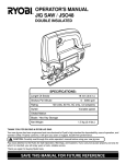
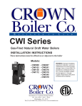
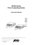
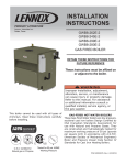
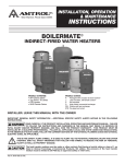
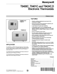
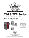
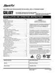
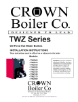
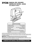
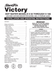
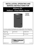
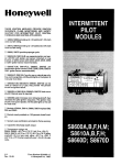
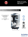
D896 Automatic Vent Damper
PRODUCT DATA
FEATURES
• 4-wire plug receptacle.
• Includes wiring harness on select models to fit plug
receptacle onto S86/S8600/S8610/S8620 /L7148/L8148
or Penn Baso G60 or G66.
• For use only on atmospheric type gas-fired furnaces
and boilers equipped with draft hoods.
• Applicable to direct spark ignition (DSI), intermittent
pilot (IP), hot surface ignition (HSI), and standing pilot
systems.
• Ambient temperature range 32°F (0°C) to 150°F (65°C).
• Requires dual automatic combination gas control
valve or two separate single function main gas valves.
• Interlock switch provides safe operation; burner fires
only with damper in open position.
GENERAL
D896 Automatic Vent Dampers are used with atmospheric
type, gas-fired equipment to reduce home heating losses by
closing off the vent between heat cycles.
• 24V operation for easy, low-cost wiring.
• Visual indicator shows damper position.
• 30-second nominal closing time for optimum energy
savings.
• Quiet motor and relay.
• Wiring harnesses available separately to fit a variety of
applications.
Contents
General ...............................................................................
Features ..............................................................................
Specifications ......................................................................
Ordering Information ...........................................................
Application ...........................................................................
Installation ...........................................................................
Settings ...............................................................................
Operation and Checkout .....................................................
Troubleshooting ...................................................................
Instructions to the Homeowner ...........................................
ANSI Standards ..................................................................
® U.S. Registered Trademark
Copyright © 1997 Honeywell Inc. • All Rights Reserved
1
1
2
2
3
4
7
7
8
9
10
68-0186
D896 AUTOMATIC VENT DAMPER
Application:
For use only on Underwriters Laboratories Inc. listed and
American Gas Association design certified atmospheric type,
gas-fired furnaces and boilers equipped with a draft hood that
has an outlet area no larger than the damper inlet area. Do
not use with oil-fired furnace or boiler, power burner, or direct
vent furnace or boiler. See Location and Mounting
subsections in Installation section for additional application
considerations.
SPECIFICATIONS
IMPORTANT
The specifications given in this publication do not
include normal manufacturing tolerances. Therefore,
this unit might not exactly match the listed
specifications. Also, this product is tested and
calibrated under closely controlled conditions, and
some minor differences in performance can be
expected if those conditions are changed.
Maximum Appliance Input Rating:
TRADELINE® Models
TRADELINE® models are selected and packaged to provide
ease of stocking, ease of handling, and maximum
replacement value. TRADELINE® model specifications are
the same as those of standard models except as noted below.
TRADELINE® Models Available:
D896 Automatic Vent Damper with 4-wire plug receptacle.
Features:
• TRADELINE® pack with cross reference label.
• 8 ft (2.4m), 4-wire cable with mating plug for D896 on one
end and mating plug for 86/S8600/S8610/S8620 or Penn
Baso G60 or G66 plug receptacle on the other end. Both
ends equipped with an outlet box connector.
Standard Models
Models:
D896 Automatic Aluminized Vent Dampers: available in 4
in. to 9 in.
D896 Stainless Steel Vent Dampers: available in 10 in. to
12 in.
Actuator assembly includes motor, relay, interlock switch,
safe-start circuit, and 4-pin plug receptacle. See Fig. 5.
Nominal Damper
Outlet Diameter
Maximum Appliance
Input
(in.)
(mm)
(Btuh)
(W)
4
102
95,000
27,835
5
127
148,000
43,364
6
152
212,000
62,116
7
178
290,000
84,970
8
203
377,000
110,461
9
229
475,000
139,175
10
254
590,000
173,500
11
280
715,000
210,300
12
305
942,000
277,000
Electrical Ratings:
Power Supply: 24 Vac, 60 Hz.
Power:
Motor: 3.0 VA maximum.
Relay: 0.1 VA maximum.
Contact Rating:
Relay: 10.0A at 250 Vac.
End Switch (Micro): 3.0A at 24 Vac.
Do not use with 120V or millivoltage, self-generating
systems.
Damper Size:
4, 5, 6, 7, 8, 9, 10, 11 and 12 in. diameter (102, 127, 152,
178, 203, 229, 254, 279 and 305 mm diameter).
ORDERING INFORMATION
When purchasing replacement and modernization products from your TRADELINE® wholesaler or distributor, refer to the
TRADELINE® Catalog or price sheets for complete ordering number.
If you have additional questions, need further information, or would like to comment on our products or services, please write or
phone:
1. Your local Home and Building Control Sales Office (check white pages of your phone directory).
2. Home and Building Control Customer Logistics
Honeywell Inc., 1885 Douglas Drive North
Minneapolis, Minnesota 55422-4386
In Canada—Honeywell Limited/Honeywell Limitée, 35 Dynamic Drive, Scarborough, Ontario M1V 4Z9.
International Sales and Service Offices in all principal cities of the world. Manufacturing in Australia, Canada, Finland, France,
Germany, Japan, Mexico, Netherlands, Spain, Taiwan, United Kingdom, U.S.A.
68-0186
2
D896 AUTOMATIC VENT DAMPER
NOTE: A minimum of a 30 VA transformer must be used
when D896 is installed with S86/S8600/S8610/
S8620.
Approvals:
American Gas Association Certified:
Certificate No. U-66-2A1.
Canadian Gas Association Design Certified:
1029AVD-9081.
Electrical Connections:
Four-wire plug receptacle.
Replacement Parts:
Damper Actuator is field replaceable without removing the
damper assembly from the stack.
197516A Wiring Harness is a 4-wire cable, 8 feet (2.5
meters) long, with D896 mating plug on one end and
mating plug for S86/S8600/S8610/S8620 or Penn Baso
G60 or G66 on the other. An outlet box connector is on
each end.
Thermostat Anticipator Setting:
0.13A.
Operating Times:
Approximate Damper Opening Time: 30 seconds.
Approximate Damper Closing Time: 30 seconds.
Temperature Ratings:
Minimum Ambient: 32°F (0°C).
Maximum Ambient: 150°F (66°C).
Maximum Furnace Stack: 575°F (302°C).
Shipping: -20°F to +120°F (-29°C to +49°C).
APPLICATION
The D896 Automatic Vent Damper is a 24 Vac, motorized
stack damper. The damper closes off the furnace or boiler
stack during the heating off-cycle. Use the D896 only on
Underwriters Laboratories Inc. listed and American Gas
Association design certified atmospheric type, gas-fired
furnaces and boilers. The furnaces or boilers must be
equipped with a draft hood that has an outlet area no larger
than the damper inlet area. Do not use with oil-fired furnace
or boiler, power burner, or direct vent furnace or boiler.
Mounting: See Fig. 2.
Vertical Stack: Any orientation.
Horizontal Stack: The damper actuator must be on the left
or right side of the vent.
IMPORTANT
Do not mount the vent damper with the actuator
above or below the vent.
Dimensions:
See Fig. 1.
DIM. F
DIM. E
DIA
A
DIA
C
DIA
B
DIM.
G
1 1 (32)
4
3
4
(70)
2
3
7
(98)
8
BODY SIZE
(REF)
DIA. A
in. (mm)
DIA. B
in. (mm)
4 (102)
5 (127)
3 15/16 (100)
4 15/16 (125)
4 (102)
5 (127)
6 (152)
7 (178)
8 (203)
5 15/16 (151)
6 15/16 (176)
7 15/16 (202)
9 (229)
10 (254)
11 (279)
12 (305)
DIM.
H
4
7/8 DIA. STD. KNOCKOUT (3)
(ONE, OPPOSITE SIDE)
DIA. C
in. (mm)
9
(116)
16
DIM. D
in. (mm)
DIM. E
in. (mm)
DIM. F
in. (mm)
4 1/16 (103)
5 1/16 (129)
1 9/16 (40)
1 9/16 (40)
4 1/2 (114)
4 1/2 (114)
6 (152)
7 (178)
8 (203)
6 1/16 (154)
7 1/16 (179)
8 1/16 (205)
1 9/16 (40)
3 3/16 (81)
3 3/16 (81)
8 15/16 (224)
9 15/16 (252)
10 15/16 (278)
9 (229)
10 (254)
11 (279)
9 1/16 (230)
10 1/16 (256)
11 1/16 (281)
11 15/16 (303)
12 (305)
12 1/16 (306)
DIM.
D
DIM. G
in. (mm)
DIM. H
in. (mm)
6 (152)
6 (152)
6 3/4 (171)
7 1/4 (184)
8 7/8 (225)
9 7/8 (251)
4 1/2 (114)
7 1/2 (191)
7 1/2 (191)
6 (152)
9 (229)
9 (229)
7 3/4 (197)
8 1/4 (209)
8 3/4 (222)
10 7/8 (276)
11 7/8 (301)
12 7/8 (327)
3 3/16 (81)
5 3/16 (132)
5 3/16 (132)
7 1/2 (191)
11 1/2 (292)
11 1/2 (292)
9 (229)
13 (330)
13 (330)
9 1/4 (235)
9 3/4 (248)
10 1/4 (260)
13 7/8 (352)
14 7/8 (378)
15 7/8 (403)
5 3/16 (132)
11 1/2 (292)
13 (330)
10 3/4 (274)
16 7/8 (428)
M11381
Fig. 1. Installation dimensions in in. (mm).
3
68-0186
D896 AUTOMATIC VENT DAMPER
IMPORTANT
1. The atmospheric draft hood outlet area must be
smaller or equal to the inlet area of the damper
assembly.
2. If a second gas valve needs to be installed, refer
to the gas valve manufacturer instructions for the
procedure.
3. Using a dual automatic valve combination gas
control or two separate gas valves is required
with the D896.
4. Do not use with L8148 or L8124 with manual/
automatic switch because the switch can override
the safety interlock in the system wiring and
cause a hazardous condition.
5. Do not install on an appliance equipped with an
automatic valve with a manual opener unless the
manual opener is rendered inoperative or the
automatic valve is replaced with an automatic
valve without a manual opener.
6. On retrofit applications, installation identification
label (provided) must be filled out by installer and
applied to outside of cover.
Location
The D896 must be installed after the furnace or boiler draft
hood. See Fig. 2. Make sure the D896 Motor Actuator is
readily visible and accessible. The damper must be located
where air can freely circulate around it.
WARNING: DO NOT INSTALL THE
VENT DAMPER WITHIN 6 IN. (152 mm)
OF COMBUSTIBLE MATERIAL.
NO
D896 MOTOR
ACTUATOR
VENT PIPE
CURVE
2
DRAFT
HOOD
1
CHIMNEY
3
INSTALLATION
When Installing this Product…
1. Read these instructions carefully. Failure to follow them
could cause a hazardous condition.
2. Check the ratings given in the instructions and on the
product to make sure the product is suitable for your
application.
3. Installer must be a trained experienced service
technician. The D896 must be installed in compliance
with local codes or the Natural Gas Installation Code
CAN/CGA-B149.1-B149.1-M91 and CSA C22.2 #3
Electrical Features of Fuel Burning Equipment, or the
National Fuel Gas Code (ANSI Z223.1—NFPA 54) and
the National Electrical Codes (ANSI C1—NFPA70). Use
the ANSI Standard Z21.66-1994 included at the end of
this specification during installation.
FURNACE OR BOILER
1
INSTALL THE VENT DAMPER TO SERVICE ONLY THE SINGLE
APPLIANCE FOR WHICH IT IS INTENDED. IF IMPROPERLY
INSTALLED, A HAZARDOUS CONDITION, SUCH AS AN EXPLOSION
OR CARBON MONOXIDE POISONING, COULD RESULT.
2
DO NOT INSTALL THE VENT DAMPER ON VENT PIPE CURVE.
3
DO NOT RUN WIRES NEAR HIGH TEMPERATURE SURFACES.
M11370
USE STAND-OFF BRACKETS IF NECESSARY.
Fig. 2. D896 location.
Do not install the D896:
— Where the stack temperature is higher than 575°F (284°C).
— Where the ambient temperature is higher than 150°F
(66°C).
— In small or enclosed spaces where temperature can
exceed 150° F (66°C). See WARNING following.
— On the vent pipe curve. See Fig. 2.
NOTE: In Canada, the damper is not certified for
retrofit application. Certification for the
suitability of the damper and appliance
combination must be determined by the
Canadian Gas Association.
WARNING
4. Install only on an appliance connected to a factory built
chimney or vent that complies with a recognized
standard, or to a masonry or concrete chimney that is
lined with a material acceptable to local code.
5. After installation is complete, check out product
operation as provided in the Checkout section. See
Exhibits A and B at the end of this specification.
Severe illness or death possible. Prevent
explosion or carbon monoxide poisoning.
Overheating can cause premature device failure. Be
sure the D896 is used to control only one appliance.
Mounting
The damper must be mounted as close as possible to the
draft hood without modifying the draft hood. The D896 can be
mounted vertically or horizontally. When vertically mounting
the vent damper, the motor actuator can be in any position.
See Fig. 3.
CAUTION
Can cause electrical shock or equipment damage.
1. Disconnect power supply.
2. Do not install within 6 in. (152 mm) of combustible
materials.
3. Do not negate the action of any existing safety or
operational control.
68-0186
WATER HEATER
Horizontal mounting requires the actuator to be located within
45 degrees directly above or directly below the horizontal
diameter of the stack pipe. See Fig. 2 and 3.
4
D896 AUTOMATIC VENT DAMPER
HORIZONTAL VENT INSTALLATION
D896
NO
YES
YES
FROM FURNACE
OR BOILER
TO CHIMNEY
FLOW
VERTICAL VENT INSTALLATION
NO
INSTALL VENT DAMPER
ONLY WITH ACTUATOR
TO SIDES OF VENT.
DO NOT MOUNT VENT
DAMPER WITH
ACTUATOR ABOVE
OR BELOW THE VENT.
TO
CHIMNEY
MOTOR
ACTUATOR
FLOW
D896
INSTALL VENT
DAMPER WITH
ACTUATOR IN
ANY POSITION.
DAMPER
BLADE PLUG
DAMPER
BLADE
FROM FURNACE
OR BOILER
M11371
FOR DSI AND IP INSTALLATIONS ONLY – PLACE PLUG ON HOLE:
HOLD DAMPER BLADE AND PUSH DOWN ON PLUG.
Fig. 3. Installing D896 Vent Damper.
M9675
Fig. 4. Installing damper blade plug.
IMPORTANT
Never mount the vent damper with the motor
actuator above or below the vent.
Wiring
WARNING
Do not install the damper blade plug if the vent damper is
installed on a system with a continuous or standing pilot. The
hole provides the minimum vent area required by code for
safe operation.
Severe illness or death possible. Prevent
explosion or carbon monoxide poisoning.
1. Use dual automatic valve combination gas
controls or two separate single function main gas
valves with the D896.
2. Do not use the D896 with an L8148 or L8124 with
a manual/automatic switch because the switch
can override the safety interlocks in the system
wiring and cause carbon monoxide buildup.
Use the damper blade plug when the damper is installed on a
system with either an intermittent pilot or direct ignition. The
plug will increase system efficiency. See Fig. 4.
To install the D896:
1. Push the female end of the vent damper over the
section of vent pipe coming from the furnace or boiler,
but after the draft hood. Push the section of the vent
pipe coming from the chimney over the male end of the
vent damper.
2. Secure the vent damper to the vent pipe with 1/2 in. (12
mm) sheet metal screws. Use only the holes provided.
3. Visually inspect the venting system for proper pitch.
Pitch must comply with local codes or ANSI Z223.1—
NFPA54.
CAUTION
1.
2.
3.
Remove the shorting plug on the S8600, S8610
or L8148E before attaching the wiring harness.
Do not permit device wiring to contact high
temperature surfaces.
Label all wires prior to disconnecting when
servicing controls. Wiring errors can cause
explosion or carbon monoxide buildup.
Important
Do not operate the system with the D896 unplugged.
Once the system has operated with the D896
plugged into the S8600, S8610 or L8148E, the
control module will not operate.
To install an additional gas valve:
1. Shut off the gas and electricity to the gas burner. (Use
the manual shutoff valve in the supply line to the
appliance.)
2. Locate a position in the supply line between the
appliance automatic gas valve and the burner.
3. At the determined position, install an approved
appropriately-sized, single-function automatic gas valve
downstream from the existing automatic gas valve.
Follow the valve manufacturer instructions for flow
direction and position.
4. Restore the gas line supply and conduct a leak test on
the gas piping and control system downstream from the
appliance shutoff valve.
D896 to L8148E, S8600F,H,M; S8610F,H
Use the wiring harness included with the D896 to wire it
according to the following instructions:
1. Connect the molex plug to the D896 Harness Cable
Connector. See Fig. 5.
2. Use Fig. 6 and 7 to connect the other end of the
harness to the furnace, boiler or control module.
3. Cycle system through at least two appliance operations.
5
68-0186
D896 AUTOMATIC VENT DAMPER
Replacing D80B, D892 or Competitive
Control with D896
D896
SERVICE
SWITCH
WARNING
IGNITION GAS
PWR LED
NORM
SERV
Bodily harm and/or death possible. Prevent
unsupervised gas flow.
Improper wiring (device malfunction) of the D80B,
D892, D896 or competitive devices can cause
unsupervised gas flow.
CALL FOR
HEAT LED
HARNESS
CABLE
CONNECTOR
1
RELAY 1K
S3 SWITCH
1
A wiring harness is included with most D896 models. Use the
harness to wire the D896 according to the furnace or boiler
manufacturer wiring instructions, if available; otherwise, follow
these instructions. If field wiring is required, see appliance
manufacturer instructions or see Fig. 8 for a typical wiring
example. See Table 1 for competitive wiring cross reference.
Always cycle system through at least two appliance
operations.
Table 1. Wiring Cross Reference.
USE STANDARD SCREWDRIVER TO MANUALLY OPEN AND
CLOSE VENT DAMPER. PLACE SCREWDRIVER IN SLOTTED
KNOB AND ROTATE COUNTERCLOCKWISE UNTIL
M11373
BOTH LEDS TURN ON.
Fig. 5. D896 with cover off.
Honeywell
D892/D896
Wires
Honeywell
D80B Wires
Johnson
Q35 Wires
EFFIKAL
RVG Wires
Yellow
Orange
Green
1
Orange
Blue and Red
White
2
Blue
Black
Red
3
Black
Yellow
Black
4
24 Vac
THERMOSTAT
D896
L8148E1166/L7148
LED 2
4
4
4
NORMAL
T
W
TV
1K
R1, R2, R3
250 OHMS
2
K1
MOTOR
WIRING
HARNESS
Z
6
2
S4
5
2
K1
C
1
N.O.
3
LED 1
FUSE
S3
S1
N.C.
3
N.C.
C
N.O.
N.C.
N.O.
SERVICE
5
S2
C
1
3
6-PRONG FEMALE MOLEX
RECEPTACLE IN L8148E
AND 5-PRONG MALE
MOLEX PLUG ON CABLE
POLARIZED 4-PRONG MALE MOLEX PLUG AND
4-PRONG FEMALE MATING PLUG ON CABLE
SWITCHES AS SHOWN: S1,S2,S3
DAMPER OPEN
DAMPER CLOSED
C1
C2
L1
L2
1K1
B1
B2
CIRCULATOR
L1
L2
(HOT)
1 POWER SUPPLY. PROVIDE DISCONNECT MEANS AND OVERLOAD
PROTECTION AS REQUIRED.
1
2 AFTER D896 VENT DAMPER IS PLUGGED TO L8148E1166, FUSE
BLOWS WHEN THERMOSTAT FIRST CLOSES. AFTER FUSE BLOWS,
L8148E1166 OPERATES ONLY WHEN VENT DAMPER IS CONNECTED.
24V GND
24V
3 LED 1 LIGHTS WHEN DAMPER IS OPEN.
4 LED 2 LIGHTS WITH CALL FOR HEAT.
5 SERVICE SWITCH. THE NORMAL SWITCH SETTING IS NORM. IF THE
SWITCH IS MOVED TO THE SERV POSITION, THE DAMPER REMAINS OPEN.
6 NO W,Z TERMINALS ON L7148.
M11382
Fig. 6. Wiring diagram for D896 connection to L8148E1166 /L7148 using wiring harness with two Molex plugs.
68-0186
6
D896 AUTOMATIC VENT DAMPER
S8600F, H, M; S8610F,H
1
GND
MV MV/PV PV (BURNER)
2
24V
GND 24V TH-W
VENT
DAMPER
PLUG
SENSE
SPARK
WIRING
HARNESS
1
POWER SUPPLY. PROVIDE DISCONNECT MEANS
AND OVERLOAD PROTECTION AS REQUIRED.
2
REMOVE PLUG ONLY IF USING VENT DAMPER. FUSE
BLOWS ON STARTUP WHEN PLUG IS REMOVED;
THEN MODULE OPERATES ONLY WHEN VENT
DAMPER IS CONNECTED.
D896
VENT
DAMPER
M11375
Fig. 7. Wiring diagram for D896 connection to S8600/S8610 using wiring harness with two Molex plugs.
1. When replacing a D80B or D892 with a D896, use the
included wire nuts to connect the D80B or D892 cable
to the D896 cable. See Fig. 9.
a. Remove the black wire from the D80B (or D892)
terminal 1.
b. Use a wire nut to connect the D80B (or D892)
black wire to the D896 blue wire.
c. Remove the orange wire from the D80B (or
D892) terminal 2.
d. Wire nut the D80B (or D892) orange wire to the
D896 yellow wire.
e. Remove the red wire from the D80B (or D892)
terminal 3 and the blue wire from the D80B (or
D892) terminal 5.
f. Wire nut the D80B (or D892) red and blue wires
to the D896 orange wire.
g. Remove the yellow wire from the D80B (or D892)
terminal 4.
h. Wire nut the D80B (or D892) yellow wire to the
D896 black wire.
2. Cycle the system through at least two appliance
operations.
furnace or boiler burner lights. When the heating cycle ends,
both LEDs turn off, the burner turns off and the damper
automatically closes. Heating system efficiency is increased
because the closed damper reduces the loss of residual
appliance heat and heated room air through the draft diverter.
D896
2
BLACK
1
ORANGE
3
BLUE
YELLOW
4
LIMIT
CONTROLLER
2
WIRING
HARNESS
THERMOSTAT
3
LIMIT
CONTROLLER
1
L1
(HOT)
L2
TRANSFORMER
DUAL AUTOMATIC
VALVE COMBINATION
TH TH GAS CONTROL
1
Snap-Tite™ Connector Release
To release the D896 cable from the knockout hole when
secured with a Snap-Tite™ Box Connector (Fig.10), slip a
screwdriver under the tab and twist.
2
1 POWER SUPPLY. PROVIDE DISCONNECT MEANS AND OVERLOAD
PROTECTION AS REQUIRED.
2 CONNECT COLORS OF WIRING HARNESS AS SHOWN.
M11372
3 ALTERNATE LIMIT CONTROLLER HOOKUP.
SETTINGS
Fig. 8. Wiring diagram for D896 connection to continuous
pilot system using wiring harness with one Molex plug.
The service switch operates in both normal (NORM ) or
service (SERV) modes. See Fig. 5.
NORM—D896 opens on a call for heat and closes at the end
of the heating cycle.
SERV—D896 remains open at the end of a call for heat. The
switch must be in the SERVICE position before manually
opening the damper.
D80B
CABLE
ORANGE
YELLOW
BLACK
YELLOW
ORANGE
OPERATION AND CHECKOUT
RED
D80B
CONNECTOR
Operation
On a call for heat, the CALL FOR HEAT LED on the actuator
lights and the damper begins to open. When the damper is
fully open, the IGNITION GAS PWR LED lights and the
D892/D896
CABLE
BLUE
BLACK
BLUE
M11383
Fig. 9. Connecting D80B, D892 Cable to D896 Cable.
7
68-0186
D896 AUTOMATIC VENT DAMPER
6. Cycle the heating system at least three times using the
thermostat or controller to assure the system is
operating safely.
Cooling
CAUTION
Damage to air conditioner condenser possible.
Do not operate cooling if outdoor temperature is below
50°F (10°C).
1. Set the thermostat or controller to COOL. Move the
setpoint to 10°F (6°C) below the room temperature.
2. Make sure the cooling system operates.
3. Check that the D896 is in the closed position. See Fig.
11.
4. Return the thermostat or controller to the desired
settings.
NOTE TO INSTALLER: Explain to the homeowner that a
yearly inspection by a trained, experienced service
technician is necessary for safe, efficient operation
of the vent damper and heating system. The
homeowner should check for deterioration from
corrosion or other sources between service
technician calls.
Fig. 10. Snap-Tite™ Box Connector release.
Checkout
Heating
1. Turn on the power supply.
2. If using a thermostat, set the heat anticipator at 0.13A.
3. Set the thermostat or controller to 10°F (6°C) above the
room temperature to call for heat.
4. Check that the D896 CALL FOR HEAT and IGNITION
GAS PWR LEDs light and that the damper opens
before the gas valve opens and the pilot or main burner
ignites. See Fig. 11.
TROUBLESHOOTING
WARNING
Fire or explosion hazard can cause property
damage, severe injury or death.
Explosion or carbon monoxide poisoning
possible.
Never apply a jumper across or short gas control
terminals or wires because this can force the D896 to
remain closed and cause an explosion.
NOTE: If a boiler gas control is sequenced by the
Aquastat® Controller, make sure that the
damper opens prior to the opening of the gas
control.
5. Turn the thermostat or controller 10°F (6°C) below the
room temperature. Make sure the LEDs turn off and the
D896 closes.
THE AIR DUCT IS CLOSED WHEN THE
INDICATOR POINTS PERPENDICULAR TO
THE DIRECTION OF THE AIR DUCT
M3431
Fig. 11. Determining damper position.
68-0186
8
THE AIR DUCT IS OPEN WHEN
THE INDICATOR POINTS IN THE
DIRECTION OF THE AIR DUCT
D896 AUTOMATIC VENT DAMPER
heating contractor for repairs. The name of the original
installer of your vent damper is on the installation label.
NOTE: If there is a power failure, the damper remains
exactly where it is at the moment of failure (open,
closed or any position in between). When power is
restored, the damper opens if the thermostat is
calling for heat or closes if the thermostat is not
calling for heat.
Check vent damper operation as follows:
1. Turn the thermostat or controller below the room
temperature to turn off the furnace or boiler. Assure the
vent damper position indicator points to the closed
position. Refer to Fig. 11.
2. Turn the thermostat or controller above the room
temperature to call for heat. Assure the vent damper
position indicator points to the open position. Refer to
Fig. 11.
3. Turn the thermostat or controller below the room
temperature again. Assure the vent damper position
indicator returns to the closed position.
4. If the system has central air conditioning, set the
thermostat or controller to COOL and turn it below the
room temperature to call for cooling. Assure the cooling
system operates with the vent damper in the closed
position.
5. Return the thermostat or controller to the desired
settings.
If system fails to start, set the thermostat 10°F (6°C) below
the room temperature for approximately three minutes, and
refer to Table 2 to troubleshoot the system.
INSTRUCTIONS TO THE HOMEOWNER
A yearly inspection by a trained, experienced service
technician is necessary for safe, efficient operation of the vent
damper and all flue product-carrying areas of the appliance.
The homeowner should check for deterioration from corrosion
and other sources between service technician calls. If
corrosion or other deterioration is noticed, contact your
Table 2. Troubleshooting.
Thermostat Setting
Set thermostat 10°F
above room temperature
to call for heat.
Set thermostat 10°F
below the room
temperature to end the
call for heat.
Possible Cause
Action
No response from D896.
Symptom
Incorrect wiring or blown
fuse.
• Check the circuit breaker or fuse and,
if necessary, reset or replace.
• Check the transformer and limit
control.
• Check for 24 Vac across resistor R1.
• Check for 24 Vac at the S8600, S8610
and L8148E.
• Check wiring and cable connections.
24 Vac is present, damper
is open, CALL FOR HEAT
LED is on, IGNITION GAS
PWR LED is on, but no
heat is produced.
Appliance ignition
system malfunction.
Check appliance ignition system.
24 Vac is present, damper
is open, CALL FOR HEAT
LED is on, IGNITION GAS
PWR LED is off, no heat is
produced.
D896 malfunction.
Replace the D896.
24 Vac is present, damper
is closed, CALL FOR HEAT
LED is off and no heat is
produced.
Incorrect wiring or D896
malfunction.
Check all wiring and cable connections.
• If 24 Vac is present across resistor
R1, replace the D896.
• If 24 Vac is not present across R1,
check the appliance ignition
system.
24 Vac is present, damper
is closed and CALL FOR
HEAT LED is off.
Incorrect wiring or D896
malfunction.
Check all wiring and cable connections.
• If 24 Vac is present across resistor
R1, replace the D896.
• If 24 Vac is not present across R1,
check the appliance ignition
system.
24 Vac is present, damper
is closed and CALL FOR
HEAT LED is on.
Incorrect wiring or D896
malfunction.
If wiring is correct and the damper does
not fully open after approximately 30
seconds, replace the D896.
LEDs turn off, but damper
does not close in
approximately 30 seconds.
Incorrect service switch
setting or D896
malfunction.
• Check if the service switch is in the
normal (NORM ) position. If not, move
the switch to the NORM position.
• If service switch is in the NORM
position, replace the D896.
9
68-0186
D896 AUTOMATIC VENT DAMPER
ANSI STANDARDS
EXHIBIT A
Procedure For Safety Inspection of an Existing Appliance Installation
10. Determine that the pilot(s), when provided, is burning
properly and that main burner ignition is satisfactory by
interrupting and reestablishing the electrical supply to
the appliance in any convenient manner.
The following procedure is intended as a guide to aid in
determining that an appliance is properly installed and is in a
safe condition for continuing use.
This procedure is predicated on central furnace, boiler and
water heater installations, and it should be recognized that
generalized procedures cannot anticipate all situations.
Accordingly, in some cases deviation from this procedure may
be necessary to determine safe operation of the equipment:
a. This procedure shall be performed prior to installation
of the automatic vent damper device.
b. If it is determined there is a condition which could result
in unsafe operation, the appliance should be shut off
and the owner advised of the unsafe condition. Do not
install the automatic vent damper device until the
unsafe condition has been corrected.
If the appliance is equipped with a continuous pilot(s), test the
pilot safety device(s) to determine if it is operating properly by
extinguishing the pilot(s) when the main burner(s) is off and
determining, after 3 minutes, that the main burner gas does
not flow upon a call for heat.
If the appliance is not provided with a pilot(s), test for proper
operation of the ignition system in accordance with the
appliance manufacturer’s lighting and operating instructions.
11. (a) Visually determine that main burner gas is burning
properly; i.e., no floating, lifting or flashback. Adjust
the primary air shutter(s) as required.
(b) If the appliance is equipped with high and low
flame controlling or flame modulation, check for
proper main burner operation at low flame.
12. Test for spillage at the draft hood relief opening after 5
minutes of main burner operation. Use the flame of a
match or candle, or smoke from a cigarette, cigar or
pipe.
13. Turn on all other fuel-burning appliances within the
same room so they will operate at their full inputs.
Follow lighting instructions for each appliance.
14. Repeat Steps 11 and 12 on the appliance being
inspected.
15. Return doors, windows, exhaust fans, fireplace
dampers and any other fuel-gas burning appliances to
their previous conditions of use.
16. Applicable only to furnaces—Check both the limit
control and the fan control for proper operation. Limit
control operation can be checked by blocking the
circulating air inlet or temporarily disconnecting the
electrical supply to the blower motor and determining
that the limit control acts to shut off the main burner
gas.
17. Applicable only to boilers—
(a) Determine that the water pumps are in operating
condition.
(b) Test low water cutoffs, automatic feed controls,
pressure and temperature limit controls, and relief
valves in accordance with the manufacturer’s
recommendations to determine they are in
operating condition.
The following steps are to be followed in making the safety
inspection:
1. Conduct a gas leakage test of the appliance piping and
control system downstream of the shutoff valve in the
supply line to the appliance.
2. Visually inspect the venting system for proper size,
horizontal pitch and vent termination, and determine
there is no blockage or restriction, leakage, corrosion
and other deficiencies which could cause an unsafe
condition.
3. Determine that the chimney or vent is acceptable to the
authority having jurisdiction.
4. Shut off all gas to the appliance and shut off any other
fuel-gas burning appliance within the same room. Use
the shutoff valve in the supply line to each appliance.
5. Inspect burners and crossovers for blockage and
corrosion.
6. Applicable only to furnaces—inspect heat exchanger for
cracks, openings or excessive corrosion.
7. Applicable only to boilers—inspect for evidence of water
or combustion product leaks.
8. Insofar as is practical, close all building doors and
windows and all doors between the space in which the
appliance is located and other spaces of the building.
Turn on clothes dryers. Turn on any exhaust fans, such
as range hoods and bathroom exhausts, so they will
operate at maximum speed. Do not operate a summer
exhaust fan. Close fireplace dampers. If, after
completing Steps 9 through 14, it is believed sufficient
combustion air is not available, refer to local codes, or
in the absence of local codes, to the National Fuel Gas
Code, ANSI Z223.1-1988 (NFPA 54), for guidance.
9. Place in operation the appliance being inspected.
Follow the lighting instructions. Adjust thermostat so
appliance will operate continuously.
Exhibit A of ANSI Standard Z21.66-1994 for Electrically Operated Automatic Vent Damper Devices
for use with Gas-Fired Appliances.
68-0186
10
D896 AUTOMATIC VENT DAMPER
EXHIBIT B
Procedure for Installing Electrically Operated Automatic Vent Damper Devices on Existing Appliances
10. Insofar as is practical, close all building doors and
windows and all doors between the space in which the
appliance is located and other spaces of the building.
Turn on clothes dryers. Turn on any exhaust fans, such
as range hoods and bathroom exhausts, so they will
operate at maximum speed. Do not operate a summer
exhaust fan. Close fireplace dampers.
11. Place appliance in operation. Follow the lighting
instructions. Adjust thermostat so appliance will operate
continuously.
12. Test for spillage at the draft hood relief opening after 5
minutes of main burner operation. Use the flame of a
match or candle, or smoke from a cigarette, cigar or
pipe.
13. (a) Visually determine that main burner gas is burning
properly; i.e., no floating, lifting or flashback. Adjust
the primary air shutter(s) as required.
(b) If the appliance is equipped with high and low
flame controlling or flame modulation, check for
proper main burner operation at low flame.
14. Determine that the pilot(s), when provided, is burning
properly and that main burner ignition is satisfactory by
interrupting and reestablishing the electrical supply to
the appliance in any convenient manner.
This procedure is intended as a guide to aid in safely
installing an electrically operated or mechanically actuated
automatic vent damper device on an existing appliance.
This procedure is based on the assumption that the history of
the specific appliance has been one of safe and satisfactory
operation.
This procedure is predicated on central furnace, boiler and
water heater installations, and it should be recognized that
generalized procedures cannot anticipate all situations.
Accordingly, in some cases deviation from this procedure may
be necessary to determine safe operation of the equipment.
The following steps are to be followed in making the
modifications:
1. Perform a safety inspection of the existing appliance
installation. See Exhibit A for the recommended
procedure for such a safety inspection.
2. Shut off all gas and electricity to the appliance. To shut
off gas use the shutoff valve in the supply line to the
appliance.
3. Install the automatic vent damper device in strict
accordance with the manufacturer’s installation
instructions. Make certain the device is not located in
that portion of the venting system which serves any
appliance other than the one for which the damper is
installed.
4. Make certain wiring connections are tight and wires are
positioned and secured so they will not be able to
contact high temperature locations.
5. When an additional automatic valve has been
incorporated or an existing gas control replaced,
conduct a gas leakage test of the appliance piping and
control system downstream of the shutoff valve in the
supply line to the appliance.
6. Visually inspect the modified venting system for proper
horizontal pitch.
7. Check that the damper and gas valve(s) are in the
correct operating sequence.
(a) The damper must be in the full open position
before the gas valve(s) opens.
(b) The damper must remain in the full open position
while the gas valve(s) is open.
(c) The gas valve(s) must be closed before damper
begins its return to the closed position.
(d) The damper shall remain in the closed position
during the off cycle of the appliance.
8. Determine the amperage draw of the gas control circuit
and damper device.
(a) Check appliance transformer for adequate
capacity.
(b) Check heat anticipator in comfort thermostat to
determine if it is properly adjusted.
9. Sequence the appliance through at least three normal
operating cycles.
If the appliance is equipped with a continuous pilot(s), test the
pilot safety device(s) to determine if it is operating properly by
extinguishing the pilot(s) when the main burner(s) is off and
determining, after 3 minutes, that the main burner gas does
not flow upon a call for heat.
If the appliance is not provided with a pilot(s), test for proper
operation of the ignition system in accordance with the
appliance manufacturer’s lighting and operating instructions.
15. Applicable only to furnaces—Check both the limit
control and the fan control for proper operation. Limit
control operation can be checked by blocking the
circulating air inlet or temporarily disconnecting the
electrical supply to the blower motor and determining
that the limit control acts to shut off the main burner
gas.
16. Applicable only to boilers—
(a) Determine that the water pumps are in operating
condition.
(b) Test low water cutoffs, automatic feed controls,
pressure and temperature limit controls, and relief
valves in accordance with the manufacturer’s
recommendations to determine they are in
operating condition.
17. Label the damper device (see 1.7.5) with information as
to:
(a) Name of qualified agency responsible for damper
installation.
(b) Date of installation.
Exhibit B of ANSI Standard Z21.66-1994 for Electrically Operated Automatic Vent Damper Device
for use with Gas-Fired Appliances.
11
68-0186
D896 AUTOMATIC VENT DAMPER
Home and Building Control
Honeywell Inc.
Honeywell Plaza
P.O. Box 524
Minneapolis MN 55408-0524
Home and Building Control
Honeywell Limited-Honeywell Limitée
155 Gordon Baker Road
North York, Ontario
M2H 2C9
Honeywell Latin American Division
Miami Lakes Headquarters
14505 Commerce Way Suite 500
Miami Lakes FL 33016
Honeywell Europe S.A.
3 Avenue du Bourget
B-1140 Brussels Belgium
Honeywell Asia Pacific Inc.
Room 3213-3225
Sun Hung Kai Centre
No. 30 Harbour Road
Wanchai
Hong Kong
Helping You Control Your World®
68-0186 J.S.
68-0186
3-97 Printed in U.S.A.
12
customer.honeywell.com