1
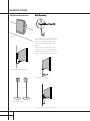
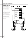
SPECIFICATIONS
HKTS 2 System
Center
Subwoofer
Frequency Response
35Hz – 20kHz (–6dB)
Recommended Power
10 – 50 watts
Amplifier
100 watts RMS
Impedance
8 ohms nominal
Bass
10" woofer, bass-reflex enclosure
Sensitivity
86dB @ 1 watt/1 meter
Dimensions (H x W x D)
18-1/4" x 15-3/4" x 16-3/4"
464mm x 400mm x 425mm
Satellites
Recommended Power
10 – 50 watts
Impedance
8 ohms nominal
Sensitivity
86dB @ 1 watt/1 meter
Tweeter
One 1/2" dome, video-shielded
Midrange
Dual 3" drivers, video-shielded
Tweeter
One 1/2" dome, video-shielded
Dimensions (H x W x D)
3-1/2" x 7-5/8" x 3-3/4"
89mm x 194mm x 93mm
Midrange
One 3" driver, video-shielded
Weight
1.89 lb/0.86kg
Weight
35.8 lb/16.2kg
Dimensions (H x W x D)
4-5/8" x 3-1/8" x 3-3/4"
117mm x 79mm x 93mm
Weight
1.1 lb/0.5kg
Refinements may be made on occasion to existing products without notice,
but will always meet or exceed original specifications unless otherwise stated.
* Trademarks of Dolby Laboratories.
DTS is a registered trademark of Digital Theater Systems, Inc.
250 Crossways Park Drive, Woodbury, New York 11797
1-800/422-8027 (USA only) Fax: 516/682-3523
© 2000 Harman Kardon, Incorporated
Printed 9/00
Part No. ai5083
HKTS 2 Home-Theater Speaker System
OWNER’S MANUAL
®
Power for the digital revolution.™
Table of Contents
3
4
4
5
6
7
7
8
9
9
10
10
11
12
2
Safety Information
Introduction
Included
Speaker Placement
Mounting Options
Speaker Connections
Speaker-Level Connection Guide
Dolby* Pro Logic* (Non-Digital) – Speaker Level
Dolby Pro Logic (Non-Digital) – Line Level
Dolby Digital or DTS® (or other Digital Surround Mode) Connection
Operation
Volume
Troubleshooting
Specifications
Read First! Important Safety Precautions!
CAUTION
RISK OF ELECTRIC SHOCK
DO NOT OPEN
CAUTION: To prevent electric shock,
do not use this (polarized)
plug with an extension cord,
receptacle or other outlet
unless the blades can
be fully inserted to
prevent blade exposure.
The lightning flash with arrowhead symbol,
within an equilateral triangle, is intended to
alert the user to the presence of uninsulated
“dangerous voltage” within the product’s
enclosure that may be of sufficient magnitude to constitute a
risk of electric shock to persons.
The exclamation point within an equilateral
triangle is intended to alert the user to the
presence of important operating and
maintenance (servicing) instructions in the
literature accompanying the appliance.
1. Read Instructions. All the safety and operating
instructions should be read before the product is
operated.
2. Retain Instructions. The safety and operating
instructions should be retained for future reference.
3. Heed Warnings. All warnings on the product and
in the operating instructions should be adhered to.
4. Follow Instructions. All operating and use
instructions should be followed.
5. Cleaning. Unplug this product from the wall outlet before cleaning. Do not use liquid cleaners or
aerosol cleaners. Use a damp cloth for cleaning.
6. Attachments. Do not use attachments not recommended by the product manufacturer, as they
may cause hazards.
7. Water and Moisture. Do not use this product
near water – for example, near a bathtub, wash bowl,
kitchen sink or laundry tub; in a wet basement;
near a swimming pool; or the like.
8. Accessories. Do not place this product on an
unstable cart, stand, tripod, bracket or table. The
product may fall, causing serious injury to a child
or adult, and serious damage to the product. Use
only with a cart, stand, tripod, bracket or table
recommended by the manufacturer, or sold with the
product. Any mounting of the product should follow
the manufacturer’s instructions, and should use
a mounting accessory recommended by the manufacturer.
9. A Product and Cart Combination
Should Be Moved with Care. Quick
stops, excessive force and uneven surfaces may cause the product and cart
combination to overturn.
10. Ventilation. Slots and openings in the cabinet
are provided for ventilation and to ensure reliable
operation of the product and to protect it from
overheating, and these openings must not be
blocked or covered. The openings should never be
blocked by placing the product on a bed, sofa, rug
or other similar surface. This product should not be
placed in a built-in installation, such as
a bookcase or rack, unless proper ventilation is provided or the manufacturer’s instructions have been
adhered to.
11. Power Sources. This product should be operated
only from the type of power source indicated on the
marking label. If you are not sure of the type of
power supply to your home, consult your product
dealer or local power company. For products intended to operate from battery power, or other sources,
refer to the operating instructions.
12. Polarization. This product may be
equipped with a polarized alternating-current-line
plug (a plug having one blade wider than the
other). This plug will fit into the power outlet only
one way. This is a safety feature. If you are unable
to insert the plug fully into the outlet, try reversing
the plug. If the plug should still fail to fit, contact
your electrician to replace your
obsolete outlet. Do not defeat the safety
purpose of the polarized plug.
13. Power-Cord Protection. Power-supply cords
should be routed so that they are not likely to be
walked on or pinched by items placed upon or
against them, paying particular attention to cords
at plugs, convenience receptacles, and the point
where they exit from the product.
14. Nonuse Periods. The power cord of the product
should be unplugged from the outlet when left
unused for long periods of time.
15. Outdoor Antenna Grounding. If an outside
antenna or cable system is connected to the product, be sure the antenna or cable system is grounded so as to provide some protection against voltage
surges and built-up static charges. Article 810 of
the National Electrical Code, ANSI/NFPA 70, provides
information with regard to proper grounding of the
mast and supporting structure, grounding of the
lead-in wire to an antenna discharge unit, size of
grounding conductors, location of antenna-discharge unit, connection to grounding electrodes,
and requirements for the grounding electrode. See
Figure 1.
16. Lightning. For added protection for this product during a lightning storm, or when it is left
unattended and unused for long periods of time,
unplug it from the wall outlet and disconnect the
antenna or cable system. This will prevent damage
to the product due to lightning and power-line
surges.
17. Power Lines. An outside antenna system should
not be located in the vicinity of overhead power
lines or other electric light or power circuits, or
where it can fall into such power lines or circuits.
When installing an outside antenna system, extreme
care should be taken to keep from touching such
power lines or circuits, as contact with them might
be fatal.
18. Overloading. Do not overload wall outlets,
extension cords, or integral convenience receptacles, as this can result in a risk of fire or electric
shock.
19. Object and Liquid Entry. Never push objects of
any kind into this product through openings, as
they may touch dangerous voltage points or shortout parts that could result in a fire or electric
shock. Never spill liquid of any kind on the product.
20. Servicing. Do not attempt to service this product yourself, as opening or removing covers may
expose you to dangerous voltage or other hazards.
Refer all servicing to qualified service personnel.
21. Damage Requiring Service. Unplug this product from the wall outlet and refer servicing to qualified service personnel under the following conditions:
a. The power-supply cord or the plug has been
damaged; or
b. Objects have fallen onto, or liquid has been
spilled into, the product; or
c. The product has been exposed to rain or water;
or
d. The product does not operate normally when following the operating instructions. Adjust only those
controls that are covered by the operating instructions, as an improper adjustment of other controls
may result in damage and will often require extensive work by a qualified technician to restore the
product to its normal operation; or
e. The product has been dropped or damaged in any
way; or
f. The product exhibits a distinct change in performance; this indicates a need for service.
22. Replacement Parts. When replacement parts
are required, be sure the service technician has used
replacement parts specified by the manufacturer or
that have the same characteristics as the original
part. Unauthorized substitutions may result in fire,
electric shock or other hazards.
23. Safety Check. Upon completion of any service
or repairs to this product, ask the service technician
to perform safety checks to determine that the
product is in proper operating condition.
24. Wall or Ceiling Mounting. The product should
be mounted to a wall or ceiling only as recommended by the manufacturer.
25. Heat. The product should be situated away from
heat sources such as radiators, heat registers,
stoves or other products (including amplifiers) that
produce heat.
Figure 1.
Example of Antenna Grounding as per
National Electrical Code ANSI/NFPA 70
Antenna Lead-In Wire
Ground Clamp
Antenna Discharge Unit (NEC Section 810-20)
Grounding Conductors (NEC Section 810-21)
Electric Service Equipment
Ground Clamps
Power Service Grounding Electrode System
(NEC Art. 250, Part H)
Part No. HCGULB 08/00
3
INTRODUCTION
Thank you for purchasing the Harman Kardon
HKTS 2, with which you are about to begin
many years of listening enjoyment. The
HKTS 2 has been custom designed to provide all the excitement and power of the
cinema experience in your own living room.
While sophisticated electronics and stateof-the-art speaker components are hard at
work within the HKTS 2 to make all of this
happen, hookup and operation are simple.
Color-keyed connections and simple controls make the HKTS 2 easy to use.
To obtain maximum enjoyment from your
new home-theater speaker system, we urge
you to take a few minutes to read through
this manual. This will ensure that connections to your receiver or preamp/processor
and amplifier or other external devices are
made properly. In addition, a few minutes
spent learning the functions of the various
controls will enable you to take advantage
of all the power and refinement the HKTS 2
is able to deliver.
If you have any questions about this product, its installation or operation, please
contact your dealer, the best local source of
information.
Description and Features
The HKTS 2 is a six-piece home theater
speaker system that includes a 10-inch,
100-watt bass-reflex powered subwoofer;
four identical 2-way, sealed enclosure satellite speakers for use in the left and right
front and rear speaker positions; a dedicated, tandem-midrange center speaker; wallmount brackets for the four satellites; and
all of the speaker cables you need to
connect your speakers to your receiver or
preamp/processor and amplifier.
The HKTS 2 subwoofer is equipped with
speaker-level inputs and outputs, line-level
inputs, a special subwoofer input for use
with equipment that furnishes a pre-filtered
subwoofer output, a level control, and an
efficient switching system that senses the
presence of an audio signal and automatically switches the unit from standby mode
to play mode.
With state-of-the-art features and timehonored circuit designs, the HKTS 2 is a
perfect complement to a Harman Kardon
receiver, and is one of the finest products
ever offered by Harman Kardon.
• Complete home-cinema speaker system
• Speakers are magnetically shielded for
flexible placement near video monitors
• Both line- and speaker-level inputs enable
compatibility with most audio components
• Subwoofer input offers superior quality
bass reproduction when used with the LFE
output of a Dolby Digital or DTS system
Although wall-mount brackets are included
for the satellite speakers, Harman Kardon
also offers optional stands, model FSTS 1,
which can be ordered through your dealer.
Harman Kardon invented the high-fidelity
receiver more than forty-seven years ago.
INCLUDED
Four satellites for left,
right and surrounds.
Wall-mount brackets.
Powered subwoofer.
4
One center-channel
speaker with adjustable support leg.
Two 20' speaker cables for connection from
receiver to subwoofer.
Two 15' speaker cables for connection from
subwoofer to front satellites.
Three 40' speaker cables for connection
from receiver to rear satellites and center
speaker.
SPEAKER PLACEMENT
Front Speakers
Surround Speakers
The front speakers should be placed the
same distance from each other as they are
from the listening position. They should be
placed at about the same height from the
floor as the listeners’ ears will be, or they
may be angled toward the listeners.
Center-Channel Speaker
0-2 ft.
Subwoofer
5 – 6 ft.
The two surround speakers should be
placed slightly behind the listening position
and, ideally, should face each other and be
at a level higher than the listeners’ ears. If
that is not possible, they may be placed on
a wall behind the listening position, facing
forward. The surround speakers should not
call attention to themselves. Experiment
with their placement until you hear a diffuse, ambient sound accompanying the
main-program material heard in the front
speakers.
The low-frequency material reproduced by
the subwoofer is mostly omnidirectional,
and this speaker may be placed in a convenient location in the room. However, the
best reproduction of bass will be heard
when the subwoofer is placed in a corner
along the same wall as the front speakers.
Experiment with subwoofer placement by
temporarily placing the subwoofer in the
listening position and moving around the
room until the bass reproduction is best.
Place the subwoofer in that location.
Stands are optional.
The center-channel speaker should be
placed slightly behind the front left and
right speakers, and no more than two feet
above or below the tweeters of the left and
right speakers. It is often convenient to set
the center speaker on top of the television
set, as shown in the drawing. Use the supplied support leg to aim it toward the listener by screwing the leg in to angle the
speaker up, or unscrewing the leg slightly
to angle the speaker down.
5
MOUNTING OPTIONS
Satellites and Surrounds
Wall Mounting
On shelves.
Attach plate to wall. The brackets should be
placed, if possible, so that the screws will
fasten into a wooden wall stud. If that is
not possible, use properly selected wall
anchors.
The customer is responsible for proper
selection and use of mounting hardware,
available through hardware stores, to properly and safely wall-mount the speakers.
On the wall. Wall brackets included.
Slide speaker onto support.
On optional stands (FSTS 1).
Place speaker and support on wall plate.
6
SPEAKER CONNECTIONS
Speaker-Level Connection Guide
Separate and strip the ends of the speaker
wire as shown. Speakers and electronics
terminals have corresponding (+) and (–)
terminals. Most manufacturers of speakers
and electronics, including Harman Kardon,
use red to denote the (+) terminal and
black for the (–) terminal.
The (+) lead of the speaker wire is noted
with a stripe. It is important to connect both
speakers identically: (+) on the speaker to
(+) on the amplifier and (–) on the speaker
to (–) on the amplifier. Wiring “out of
phase” results in thin sound, weak bass and
a poor stereo image.
With the advent of multichannel
surround-sound systems, connecting all
of the speakers in your system with the correct polarity remains equally important in
order to preserve the proper ambience and
directionality of the program material.
7
SPEAKER CONNECTIONS (continued)
Dolby Pro Logic
(Non-Digital) – Speaker Level
Left Front
–
+
–
USE THIS INSTALLATION METHOD FOR
DOLBY PRO LOGIC APPLICATIONS (NOT
DOLBY DIGITAL, DTS OR OTHER DIGITAL
PROCESSING), WHERE THE RECEIVER/
PROCESSOR DOES NOT HAVE A SUBWOOFER OUTPUT, OR A VOLUMECONTROLLED PREAMP (LINE-) LEVEL
OUTPUT:
Right Front
Center
+
–
–
+
–
+
–
+
–
+
+
L
Connect your receiver or amplifier’s front
left and right speaker terminals to the left
and right terminals on the subwoofer that
are marked “Speaker-Level Input.” Connect
the left and right terminals on the subwoofer that are marked “Speaker-Level
Output” to the corresponding terminals on
the back of your front left and right speakers.
Speaker-Level
Output
R
Subwoofer
High Level
L
Connect your receiver or amplifier’s center,
and left and right surround-speaker
terminals to the corresponding terminals on
the back of your center, and left and right
surround speakers.
Speaker-Level
Input
R
Receiver
Left Front
Left Surround
Left Surround
–
8
+
Center
Right Front
Right Surround
Right Surround
–
+
SPEAKER CONNECTIONS (continued)
Dolby Pro Logic
(Non-Digital) – Line Level
Center
–
+
Left
Front
–
+
USE THIS INSTALLATION METHOD FOR
DOLBY PRO LOGIC APPLICATIONS (NOT
DOLBY DIGITAL, DTS OR OTHER DIGITAL
PROCESSING), WHERE THE RECEIVER/
PROCESSOR IS EQUIPPED WITH A SUBWOOFER OUTPUT, OR A VOLUMECONTROLLED PREAMP (LINE-) LEVEL
OUTPUT:
Use RCA-type patch cords to connect the
line-level subwoofer outputs on your receiver
or amplifier to the line-level inputs on the
subwoofer. IMPORTANT: Do not use the
SUB input on the subwoofer with Dolby
Pro Logic processors. Note: If your receiver
or amplifier only has one subwoofer output
jack, then you will need to use a Y-connector
(not included). Plug the male end of the
Y-connector into your receiver or amplifier’s
subwoofer output jack, and connect each of
the two female ends to separate RCA-type
patch cords. Finally, plug the RCA-type
patch cords into the line-level inputs on the
subwoofer.
Right
Front
–
+
Subwoofer
R
L
LineLevel
Input
Left
Front
Subwoofer
Out
R
Left
Rear
Left
Surround
–
+
Right
Front
L
Center
Receiver
Right
Rear
Right
Surround
–
+
Connect each speaker to the corresponding
speaker terminals on your receiver or amplifier.
Dolby Digital or DTS (or other Digital Surround Mode) Connection
RECEIVER
SUBWOOFER
L
SUBWOOFER/LFE OUT
LINE
LEVEL
INPUT
SUB
R
USE THIS INSTALLATION METHOD FOR
DOLBY DIGITAL, DTS OR OTHER DIGITAL
SURROUND PROCESSORS:
Use the line-level input jack marked “SUB”
for the Low-Frequency Effects channel.
Connect this jack to the subwoofer output
or LFE output on your receiver or amplifier.
Connect each speaker to the corresponding
speaker terminals on your receiver or
amplifier.
Make sure that you have configured your
surround-sound processor for “Subwoofer
On.” The front left, front right, center and
rear speakers should all be set to “Small.”
9
OPERATION
Move the Master Power switch (marked
“Power” ¡) to the “•” (On) position to
use the subwoofer. The HKTS 2 subwoofer
will automatically turn itself on or go into
standby (sleep) mode when left in the
standby mode (“Auto/On” switch ™ in the
“Auto” position). When your receiver or
amplifier is off, or is not sending program
material to the subwoofer, the subwoofer
will be in standby mode and the LED will
£
™
turn red. When the subwoofer senses an
audio signal, it will automatically turn itself
on and the LED will turn green. If the
subwoofer does not sense a signal after
approximately twenty minutes, it will
automatically go into standby mode.
When the “Auto/On” switch ™ is switched
to the “On” position, the subwoofer will
remain on, whether or not program material
is playing.
¡
SUBWOOFER
LEVEL
AC 120V~60Hz
200W
POWER
MIN
MAX
RED: STAND BY —
O — GREEN: ON
FUSE
2.5A/250V
TYPE T
ON n
AUTO n
R
L
LINE
LEVEL
INPUT
SUB-TS 2
SUB
OUT
IN
This area is designed to be quite warm
during normal operation.
+
CAUTION
R
RISK OF ELECTRIC SHOCK
DO NOT OPEN
HIGH –
LEVEL
–
L
+
+
IMPORTANT: CONNECT STRIPED WIRE TO RED ( ) SPEAKER TERMINAL.
Volume
Volume can be adjusted using the
Subwoofer Level Control £, as shown
below.
Subwoofer
Level
MIN
10
MAX
Subwoofer
Level
MIN
MAX
If you will be away from home for an
extended period of time, or if the subwoofer will not be used, switch the Master
Power switch ¡ to the “Off” position.
TROUBLESHOOTING
If there is no sound from any of the
speakers:
• Check that receiver/amplifier is on and a
source is playing.
• Check that the powered subwoofer is
plugged in and its Power switch ¡ is
switched on to the “•” position.
• Check all wires and connections between
receiver/amplifier and speakers. Make sure
all wires are connected. Make sure none
of the speaker wires are frayed, cut or
punctured.
• Review proper operation of your
receiver/amplifier.
If there is no sound coming from one
speaker:
• Check the “Balance” control on your
receiver/amplifier.
• Check all wires and connections between
receiver/amplifier and speakers. Make sure
all wires are connected. Make sure none
of the speaker wires are frayed, cut or
punctured.
• In Dolby Digital or DTS modes, make sure
that the receiver/processor is configured so
that the speaker in question is enabled.
If there is no sound from the center
speaker:
• Check all wires and connections between
receiver/amplifier and speaker. Make sure
all wires are connected. Make sure none
of the speaker wires are frayed, cut or
punctured.
• If your receiver/processor is set in Dolby
Pro Logic mode, make sure the center
speaker is not in phantom mode.
• If your receiver/processor is set in Dolby
Digital or DTS mode, make sure the
receiver/processor is configured so
that the center speaker is enabled.
If the system plays at low volumes
but shuts off as volume is increased:
• Check all wires and connections between
receiver/amplifier and speakers. Make sure
all wires are connected. Make sure none
of the speaker wires are frayed, cut or
punctured.
• If more than one pair of main speakers is
being used, check the minimum impedance
requirements of your receiver/amplifier.
• Review the operation of your DVD player
and the jacket of your DVD to make sure
that the DVD features the desired Dolby
Digital or DTS mode, and that you have
properly selected that mode using both the
DVD player’s menu and the DVD disc’s
menu.
If there is low (or no) bass output:
• Make sure the connections to the left and
right “Speaker Inputs” have the correct
polarity (+ and –).
• Make sure the subwoofer is plugged into
an active electrical outlet.
• Make sure the powered subwoofer is
plugged in and its power switch ¡ is
switched on to the “•” position.
• In Dolby Digital or DTS modes, make
sure your receiver/processor is configured
so that the subwoofer and LFE output are
enabled.
If there is no sound from the surround speakers:
• Check all wires and connections between
receiver/amplifier and speakers. Make sure
all wires are connected. Make sure none
of the speaker wires are frayed, cut or
punctured.
• Review proper operation of your
receiver/processor and its surround-sound
features.
• Make sure the movie or TV show you are
watching is recorded in a surround-sound
mode. If it is not, check to see if your
receiver/processor has other surround
modes you may use.
• In Dolby Digital or DTS modes, make sure
your receiver/processor is configured so that
the surround speakers are enabled.
11