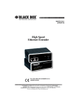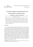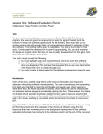
1
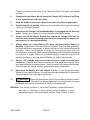
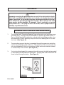
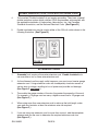
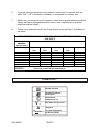
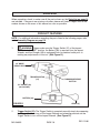
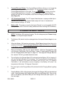
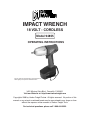
IMPACT WRENCH
18 VOLT - CORDLESS
Model 94855
OPERATING INSTRUCTIONS
Due to continuing improvement, actual product may
differ slightly from product described herein.
3491 Mission Oaks Blvd., Camarillo, CA 93011
Visit our Web site at: http://www.harborfreight.com
Copyright© 2006 by Harbor Freight Tools®. All rights reserved. No portion of this
manual or any artwork contained herein may be reproduced in any shape or form
without the express written consent of Harbor Freight Tools.
For technical questions, please call 1-800-444-3353.
PRODUCT SPECIFICATIONS
Item
Description
Power Source
18 VDC Battery, 1.3 Ah.
Battery Lock: Yes (Clips).
Cell Type: Ni-Cad /1300 mAh.
Cell Count: 15 Cells.
Charge Time: 3-5 Hours.
Plug Type: 2 Prong.
Charger Input
120 VAC / 60 Hz.
Charger Output
24 VDC / 400 mA. 9.6 Amp.
Tool Drive
1/2” w/ Spring Ball & Clip.
Maximum Torque
150 FT. Lbs.
Impact Speed
1900 BPM.
Socket Size
1/2” (Qty. 1) (not included)
Weight
5.35 Pounds.
Variable Speed
0- 2400 RPM
SAVE THIS MANUAL
You will need this manual for the safety warnings and precautions,
assembly, operating, inspection, maintenance and cleaning procedures,
parts list and assembly diagram. Keep your invoice with this manual.
Write the invoice number on the inside of the front cover. Keep this
manual and invoice in a safe and dry place for future reference.
GENERAL SAFETY RULES
WARNING!
READ AND UNDERSTAND ALL INSTRUCTIONS
Failure to follow all instructions listed below may result in
electric shock, fire, and/or serious injury.
SAVE THESE INSTRUCTIONS
WORK AREA
1.
2.
Keep your work area clean and well lit. Cluttered benches and dark areas
invite accidents.
Do not operate power tools in explosive atmospheres, such as in the
presence of flammable liquids, gases, or dust. Power tools create sparks
REV 12/06
SKU 94855
PAGE 2
which may ignite the dust or fumes.
3.
Keep bystanders, children, and visitors away while operating a power tool.
Distractions can cause you to lose control. Protect others in the work area from
debris such as chips and sparks. Provide barriers or shields as needed.
ELECTRICAL SAFETY
4.
Grounded tools must be plugged into an outlet properly installed and grounded
in accordance with all codes and ordinances. Never remove the grounding
prong or modify the plug in any way. Do not use any adapter plugs. Check
with a qualified electrician if you are in doubt as to whether the outlet is properly
grounded. If the tools should electrically malfunction or break down, grounding
provides a low resistance path to carry electricity away from the user.
5.
Double insulated tools are equipped with a polarized plug (one blade is wider
than the other). This plug will fit in a polarized outlet only one way. If the plug
does not fit fully in the outlet, reverse the plug. If it still does not fit, contact a
qualified electrician to install a polarized outlet. Do not change the plug in
any way. Double insulation
eliminates the need for the three wire grounded
power cord and grounded power supply system.
6.
Avoid body contact with grounded surfaces such as pipes, radiators, ranges,
and refrigerators. There is an increased risk of electric shock if your body is
grounded.
7.
Do not expose power tools to rain or wet conditions. Water entering a power
tool will increase the risk of electric shock.
8.
Do not abuse the Power Cord. Never use the Power Cord to carry the tools or
pull the Plug from an outlet. Keep the Power Cord away from heat, oil, sharp
edges, or moving parts. Replace damaged Power Cords immediately. Damaged
Power Cords increase the risk of electric shock.
9.
When operating a power tool outside, use an outdoor extension cord marked
“W-A” or “W”. These extension cords are rated for outdoor use, and reduce the
risk of electric shock.
PERSONAL SAFETY
10.
Stay alert. Watch what you are doing, and use common sense when operating
a power tool. Do not use a power tool while tired or under the influence of
drugs, alcohol, or medication. A moment of inattention while operating power
tools may result in serious personal injury.
SKU 94855
PAGE 3
11.
Dress properly. Do not wear loose clothing or jewelry. Contain long hair.
Keep your hair, clothing, and gloves away from moving parts. Loose clothes,
jewelry, or long hair can be caught in moving parts.
12.
Avoid accidental starting. Be sure the Power Switch is off before plugging in.
Carrying power tools with your finger on the Power Switch, or plugging in power
tools with the Power Switch on, invites accidents.
13.
Remove adjusting keys or wrenches before turning the power tool on.
A wrench or a key that is left attached to a rotating part of the power tool may result
in personal injury.
14.
Do not overreach. Keep proper footing and balance at all times. Proper footing
and balance enables better control of the power tool in unexpected situations.
15.
Use safety equipment. Always wear eye protection. Dust mask, non-skid safety
shoes, hard hat, or hearing protection must be used for appropriate conditions.
TOOL USE AND CARE
16.
Use clamps (not included) or other practical ways to secure and support the
workpiece to a stable platform. Holding the work by hand or against your body is
unstable and may lead to loss of control.
17.
Do not force the tool. Use the correct tool for your application. The correct
tool will do the job better and safer at the rate for which it is designed.
18.
Do not use the power tool if the Power Switch does not turn it on or off. Any
tool that cannot be controlled with the Power Switch is dangerous and must be
replaced.
19.
Disconnect the Power Cord Plug from the power source before making any
adjustments, changing accessories, or storing the tool. Such preventive safety
measures reduce the risk of starting the tool accidentally.
20.
Store idle tools out of reach of children and other untrained persons. Tools
are dangerous in the hands of untrained users.
21.
Maintain tools with care. Keep cutting tools sharp and clean. Properly
maintained tools with a sharp cutting edge are less likely to bind and are easier to
control. Do not use a damaged tool. Tag damaged tools “Do not use” until repaired.
SKU 94855
PAGE 4
22.
Check for misalignment or binding of moving parts, breakage of parts, and
any other condition that may affect the tool’s operation. If damaged, have the
tool serviced before using. Many accidents are caused by poorly maintained
tools.
23.
Use only accessories that are recommended by the manufacturer for your
model. Accessories that may be suitable for one tool may become hazardous
when used on another tool.
SERVICE
24.
Tool service must be performed only by qualified repair personnel. Service or
maintenance performed by unqualified personnel could result in a risk of injury.
25.
When servicing a tool, use only identical replacement parts. Follow
instructions in the “Inspection, Maintenance, And Cleaning” section of this
manual. Use of unauthorized parts or failure to follow maintenance instructionsmay
create a risk of electric shock or injury.
SPECIFIC SAFETY RULES
1.
Maintain a safe working environment. Keep the work area well lit. Make sure
there is adequate surrounding workspace. Always keep the work area free of
obstructions, grease, oil, trash, and other debris. Do not use the Impact Wrench in
areas near flammable chemicals, dusts, and vapors. Do not use this product in a
damp or wet location.
2.
Maintain labels and nameplates on the Impact Wrench. These carry important
information. If unreadable or missing, contact Harbor Freight Tools for a replacement.
3.
When using the Impact Wrench, always maintain a firm grip on the tool with
both hands.
4.
Do not use the Impact Wrench or Charger (48) if it has been dropped, damaged,
left outdoors, or immersed in liquid.
5.
Do not charge the Battery (30) when the temperature is below 50 degrees
Fahrenheit or above 104 degrees Fahrenheit.
6.
Do not shake, drop, or strike the Battery (30).
7.
To avoid electrical shock, do not pull or carry the Charger (48) by its Power
Cord or pull the Power Cord around sharp corners or edges. Do not unplug the
SKU 94855
PAGE 5
Charger by pulling on the Power Cord. Keep the Power Cord away from heated
surfaces.
8.
To avoid electrical shock, do not handle the Charger (48), its Power Cord Plug,
or the Impact Wrench with wet hands.
9.
Keep the Handle of the Impact Wrench dry, clean, free from oil and grease.
10.
Avoid unintentional starting. Make sure you are prepared to begin work before
turning on the Impact Wrench.
11.
Never leave the Charger (48) unattended when it is plugged into an electrical
outlet. Make sure to unplug it from its electrical outlet before leaving.
12.
Always turn off the Impact Wrench and unplug the Charger (48) from its
electrical outlet before changing accessories or performing any inspection,
maintenance, or cleaning procedures.
13.
Always switch to a fresh Battery (30) when tool performance begins to
diminish. Severe heat is most destructive to a Battery. The more heat generated,
the faster the Battery loses power. A Battery that gets too hot can be permanently
damaged. Never over-discharge a Battery by using the tool even after tool
performance is decreasing. Never attempt to discharge a tool’s Battery by continuing
to pull the tool’s trigger. When tool performance begins to diminish stop the tool,
recharge the Battery, and use the fresh Battery for optimal performance.
14.
Battery (30) leakage may occur under extreme usage or temperature
conditions. If Battery fluid comes in contact with skin, wash with soap and water
and rinse with lemon juice and vinegar. If the fluid comes into contact with the eyes,
flush with water for several minutes and contact a doctor immediately.
15.
Never burn the Battery, as it can explode in a fire. Do not charge the Impact
Wrench if it has a leaking Battery. Contact local solid waste authorities for instructions
on correct disposal or recycling of the Battery.
16.
WARNING! People with pacemakers should consult their physician(s) before
using this product. Operation of electrical equipment in close proximity to a heart
pacemaker could cause interference or failure of the pacemaker.
WARNING: This product contains or, when used, produces a chemical known to
the State of California to cause cancer and birth defects or other
reproductive harm. (California Health & Safety Code 25249.5, et seq.)
SKU 94855
PAGE 6
GROUNDING
WARNING!
Improperly connecting the grounding wire can result in the risk of electric shock.
Check with a qualified electrician if you are in doubt as to whether the outlet is
properly grounded. Do not modify the power cord plug provided with the tool.
Never remove the grounding prong from the plug. Do not use the tool if the
power cord or plug is damaged. If damaged, have it repaired by a service
facility before use. If the plug will not fit the outlet, have a proper outlet installed by a qualified electrician.
GROUNDED TOOLS: TOOLS WITH THREE PRONG PLUGS
1.
Tools marked with “Grounding Required” have a three wire cord and three prong
grounding plug. The plug must be connected to a properly grounded outlet. If
the tool should electrically malfunction or break down, grounding provides a low
resistance path to carry electricity away from the user, reducing the risk of electric shock. (See Figure A.)
2.
The grounding prong in the plug is connected through the green wire inside the
cord to the grounding system in the tool. The green wire in the cord must be the
only wire connected to the tool’s grounding system and must never be attached
to an electrically “live” terminal. (See Figure A.)
3.
Your tool must be plugged into an appropriate outlet, properly installed and grounded
in accordance with all codes and ordinances. The plug and outlet should look like
those in the following illustration. (See Figure A.)
FIGURE A
SKU 94855
PAGE 7
DOUBLE INSULATED TOOLS: TOOLS WITH TWO PRONG PLUGS
4.
Tools marked “Double Insulated” do not require grounding. They have a special
double insulation system which satisfies OSHA requirements and complies with
the applicable standards of Underwriters Laboratories, Inc., the Canadian
Standard Association, and the National Electrical Code. (See Figure B.)
5.
Double insulated tools may be used in either of the 120 volt outlets shown in the
following illustration. (See Figure B.)
FIGURE B
EXTENSION CORDS
1.
Grounded tools require a three wire extension cord. Double Insulated tools
can use either a two or three wire extension cord.
2.
As the distance from the supply outlet increases, you must use a heavier gauge
extension cord. Using extension cords with inadequately sized wire causes a
serious drop in voltage, resulting in loss of power and possible tool damage.
(See Figure C, next page.)
3.
The smaller the gauge number of the wire, the greater the capacity of the cord.
For example, a 14 gauge cord can carry a higher current than a 16 gauge cord.
(See Figure C.)
4.
When using more than one extension cord to make up the total length, make
sure each cord contains at least the minimum wire size required.
(See Figure C.)
5.
If you are using one extension cord for more than one tool, add the nameplate
amperes and use the sum to determine the required minimum cord size.
(See Figure C.)
SKU 94855
PAGE 8
6.
If you are using an extension cord outdoors, make sure it is marked with the
suffix “W-A” (“W” in Canada) to indicate it is acceptable for outdoor use.
7.
Make sure your extension cord is properly wired and in good electrical condition.
Always replace a damaged extension cord or have it repaired by a qualified
electrician before using it.
8.
Protect your extension cords from sharp objects, excessive heat, and damp or
wet areas.
RECOMMENDED MINIMUM WIRE GAUGE FOR EXTENSION CORDS*
(120 VOLT)
NAMEPLATE
AMPERES
(At Full Load)
– 2.0
2.1 – 3.4
3.5 – 5.0
5.1 – 7.0
7.1 – 12.0
12.1 – 16.0
16.1 – 20.0
FIGURE C
EXTENSION CORD LENGTH
25
50
75
Feet
Feet
Feet
18
18
18
18
18
18
18
18
16
18
16
14
18
14
12
14
12
10
12
10
* Based on limiting the line voltage drop
to five volts at 150% of the rated amperes.
SYMBOLOGY
Double Insulated
Canadian Standards
Association
Underwriters
Laboratories, Inc.
V~
A
no
xxxx/min.
SKU 94855
Volts Alternating Current
Amperes
No Load Revolutions
per Minute (RPM)
PAGE 9
100
Feet
18
16
14
12
10
-
16
14
12
12
-
UNPACKING
When unpacking, check to make sure all the parts shown on the Parts List on page 14
are included. If any parts are missing or broken, please call Harbor Freight Tools at the
number shown on the cover of this manual as soon as possible.
PRODUCT FEATURES
NOTE: For additional information regarding the parts listed in the following pages, refer
to the Assembly Diagram on page 15.
1.
WARNING! Always make sure the Trigger Switch (21) of the Impact
Wrench is in its “OFF” position, the Battery (30) is removed from the Impact
Wrench, and the Charger (48) is unplugged from its electrical outlet prior to
making any adjustments to the tool. (See Figure D.)
1/2” DRIVE
IMPACT HEAD
TRIGGER SWITCH
(21)
FORWARD/REVERSE
BUTTON
1/2” SOCKET (49)
(not included)
BATTERY (30)
FIGURE D
2.
STRAP (3)
Trigger Switch (21): The Trigger Switch is operated manually simply by squeezing
the Trigger Switch to turn on the Impact Wrench and releasing pressure on the
Trigger Switch to turn off the Impact Wrench. (See Figure D.)
SKU 94855
PAGE 10
REV 12/06
3.
Forward/Reverse Button: The Forward/Reverse Button allows you to change the
rotational direction of the Impact Wrench. For a clockwise rotation, move the
Forward/Reverse Button to the right. For a counterclockwise rotation, move the
Forward/Reverse Button to the left. To avoid damage to the Impact Wrench,
always wait until the tool completely stops before changing rotational directions.
(See Figure D.)
4.
1/2” Drive Impact Head: The 1/2” Impact Head features a spring and ball clip to
securely hold a socket. The Impact Head accepts all sizes of standard and
metric sockets having a 1/2” drive.
5.
Battery (30): The power source for the Impact Wrench is a re-chargeable, 18 VDC
Battery. Make sure to follow all safety precautions when working with the Battery.
TO CHARGE THE IMPACT WRENCH
1.
NOTE: The Battery (30) requires charging. The first charge requires 5 hours charge
time prior to using the Impact Wrench.
2.
The Battery (30) should only be recharged when the Impact Wrench begins to run
slowly.
3.
When the Battery (30) requires recharging, a 3 to 5 hour charge allows the tool to
operate at full power. Do not recharge the Battery longer than 5 hours, as damage
to the Battery and/or Impact Wrench will occur.
4.
Remove the Battery (30) from the Impact Wrench. Slide the Charging Base (50)
onto the top of the Battery (30) (see Figure 1, page 12) and plug the Charger (48)
into the Charging Base (see Figure 2, page 12). Then plug the Charger (48) into
the nearest 120 Volt, grounded electrical outlet.
5.
The red light on the Charger Base (50) indicates that the Battery (30) is charging. It
will stay lit while the Battery (30) is charging. The Charging Base automatically stop
charging the Battery (30) when the battery gets too hot (over 113 degrees
Fahrenheit). It will automaticity resume charging of the Battery (30) when the
temperature falls below 113 degrees Fahrenheit.
6.
The green light on the Charger Base (50) indicates that the Charging Base is getting
power.
7.
Once the Battery (30) is fully charged, disconnect the Charger (48) from the electrical
outlet. Next disconnect the Charger Base (50) from the Battery (30). Press in the
tabs on the Battery (30) while sliding out the Charger Base (50) (see Figure 1, on
the next page).
SKU 94855
PAGE 11
CHARGER BASE (50)
BATTERY (30)
GREEN POWER
INDICATOR
LIGHTTabs
Tabs
Tabs
CHARGER BASE (50)
NOTE: To connect the Charger Base (50)
to the Battery (30), press in the tabs on
the Battery while you slide the Charger
Base forward.
FIGURE 1
PLUG INTO
120 VOLT, GROUNDED,
ELECTRICAL OUTLET
RED CHARGING
INDICATOR
LIGHT
FIGURE 2
OPERATING INSTRUCTIONS
1.
Before installing the Socket (49), make sure the Battery (30) is removed from the
Impact Wrench to avoid accidental starting. Then, firmly insert and lock in
place the Socket onto the 1/2” Impact Head of the tool.
2.
Whenever possible, secure the work piece in place, using a vise or clamps (not
included).
3.
Insert the fully charged Battery (30) into the Handle of the Impact Wrench, and
rotate the Battery 180 degrees to lock the Battery in place.
4.
Use the Forward/Reverse Button to select the turning rotation of the Impact
Wrench.
5.
Insert the Socket (49) onto the nut that is to be loosened/tightened. NOTE: If
using the accessory 1/2” Socket, the nut itself must be 1/2”.
6.
Make sure to hold the Impact Wrench firmly with both hands, as torque from the
Motor will cause the tool to twist. Then, squeeze the Trigger Switch (21) to turn
on the Impact Wrench. The more you depress the Trigger Switch (21) the faster
the Impact Wrench will turn.
7.
When finished, release the Trigger Switch (21) to stop the Impact Wrench. Then,
remove the Battery (30) and Socket (49) from the tool.
SKU 94855
PAGE 12
INSPECTION, MAINTENANCE, AND CLEANING
1.
WARNING! Always turn the Trigger Switch (21) to its “OFF” position,
and unplug the Charger (48) from its electrical outlet before performing any
inspection, maintenance, or cleaning.
2.
BEFORE EACH USE, inspect the general condition of the Impact Wrench.
Check for misalignment or binding of moving parts, cracked or broken parts,
leaking Battery, damaged Charger wiring, chipped or broken sockets, and any
other condition that may affect its safe operation. If abnormal noise or vibration
occurs, have the problem corrected before further use.
Do not use damaged equipment.
3.
DAILY: With a clean cloth, remove all dirt, grease, and oil from the Impact Wrench.
Do not immerse the Impact Wrench in any liquids.
PLEASE READ THE FOLLOWING CAREFULLY
THE MANUFACTURER AND/OR DISTRIBUTOR HAS PROVIDED THE PARTS LIST AND ASSEMBLY
DIAGRAM IN THIS MANUAL AS A REFERENCE TOOL ONLY. NEITHER THE MANUFACTURER OR
DISTRIBUTOR MAKES ANY REPRESENTATION OR WARRANTY OF ANY KIND TO THE BUYER THAT
HE OR SHE IS QUALIFIED TO MAKE ANY REPAIRS TO THE PRODUCT, OR THAT HE OR SHE IS
QUALIFIED TO REPLACE ANY PARTS OF THE PRODUCT. IN FACT, THE MANUFACTURER AND/OR
DISTRIBUTOR EXPRESSLY STATES THAT ALL REPAIRS AND PARTS REPLACEMENTS SHOULD BE
UNDERTAKEN BY CERTIFIED AND LICENSED TECHNICIANS, AND NOT BY THE BUYER. THE BUYER
ASSUMES ALL RISK AND LIABILITY ARISING OUT OF HIS OR HER REPAIRS TO THE ORIGINAL
PRODUCT OR REPLACEMENT PARTS THERETO, OR ARISING OUT OF HIS OR HER INSTALLATION
OF REPLACEMENT PARTS THERETO.
SKU 94855
PAGE 13
PARTS LIST
(not included)
50
Charger Base
1
REV 12/06
SKU 94855
PAGE 14
ASSEMBLY DIAGRAM
25
2
6
27
38
12
13
23
19
32 34 18 20
9
4
24
39
26
21
42
43
28
5
11
33
47
7
40
3
46
41
17
16
49: 1/2” SOCKET (not included)
35
36
14
31
45
30
44
1
8
29
27
37
48
50
NOTE: Some parts are listed and shown for illustration purposes only, and are not
available individually as replacement parts.
REV 12/06
SKU 94855
PAGE 15