1
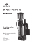
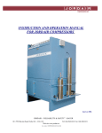
Instructions-Parts
24G621 Agitator Speed Controller
Accessory
3A1315A
ENG
Accessory kit to control and automatically maintain the speed of an air-powered agitator.
For professional use only.
Important Safety Instructions
Read all warnings and instructions in this manual
and in your separate agitator manual. Save these instructions.
Patent Pending
TI17253a
PROVEN QUALITY. LEADING TECHNOLOGY.
Contents
Installation.......................................................... 3
Kit Parts ............................................................. 8
Operation ........................................................... 5
Technical Data ................................................... 10
Troubleshooting.................................................. 6
Notes ............................................................... 11
Repair................................................................ 7
Graco Standard Warranty.................................... 12
2
3A1315A
Installation
2. Install the push-to-connect air tube connector
(21) in place of the needle valve.
The agitator speed controller fits the following Graco
pneumatic rotary motors:
Motor Part No.
101140
16A871
101388
111310
NOTE: Before installing, ensure that the agitator
air motor has at least 5 in. (12.7 cm) of vertical
clearance and 4 in. (10.2 cm) of horizontal clearance
in all directions around it.
NOTE: If you are using an air line lubricator, install it
in the air line upstream of the speed controller.
TI17256a-1
3. Screw the compression nut (24) onto the flange
connector (23) finger-tight. Place the connector
assembly (23, 24) onto the exposed shaft of the
air motor, flange connector side down.
1. Remove the air motor top cap (A) and needle
valve (B) using the multi-function wrench (26).
Store these parts in a safe place; they will be
needed if the speed controller is ever removed.
TI17254a-1
TI17257a-1
TI17255a-1
3A1315A
3
4. Using the allen wrench (25) and multi-function
wrench (26), tighten the compression nut (24)
onto the flange connector at least 1/8 turn past
finger tight. This provides a firm connection to
the motor shaft.
6. Connect the air tubing (27) between the speed
controller tube connector (29) and the air motor
tube connector (21).
TI17258a-1
5. Ensure that the drive shaft hex (C) engages the
hex socket (D) in the flange connector. Screw
the base of the speed controller into the threads
at the top of the air motor until hand tight.
TI17253a-1
7. Return the unit to service. Connect the main air
line to the quick-disconnect fitting (28) on the
speed controller.
TI17259a-1
4
3A1315A
Operation
Connect the main air line to the quick disconnect
fitting (28) on the agitator speed controller. Do not
exceed the maximum air inlet pressure of 100 psi
(0.7 MPa, 7.0 bar).
Set the agitator speed using the knob (16) on
the top of the speed controller. Turn the knob
counterclockwise (outward) to increase agitator
speed. Turn the knob clockwise (inward) to decrease
agitator speed. Once the desired agitator speed is
set, the speed controller will maintain that speed by
regulating the airflow to the air motor.
16
Turn knob counterclockwise
to increase speed.
Turn knob clockwise
to decrease speed.
28
TI17260a-1
To shut off the agitator, disconnect the air supply or
turn the speed adjustment knob clockwise until it is
fully closed.
3A1315A
5
Troubleshooting
Problem
Solution
The speed controller does not adjust for a change in
load, or shuts off before the knob (16) is turned all
the way down.
Remove the needle (13). and liberally lubricate the
needle and o-ring (33) with multi-purpose lithium
based grease.
The speed controller does not maintain a consistent
speed, or the speed rapidly fluctuates.
Replace the needle (13), u-cup (11), and o-ring (33),
using Repair Kit 24J886.
Upon startup, the motor runs away for a few seconds
before the speed controller slows it down.
Ensure that the compression nut (24) and flange
connector (23) are securely tightened to the motor
shaft. See Installation, page 3 .
6
3A1315A
Repair
NOTE: To repair the agitator, see your separate
agitator manual.
NOTE: Repair Kit 24J886 is available. Order the kit
separately. Kit parts are marked with an asterisk, for
example (3*). For the best results use all the parts
in the kit.
NOTE: Use multi-purpose lithium based grease
where ever lubrication is required. Order Part No.
111920.
1. Disconnect the main air line to the speed
controller.
2. Disconnect the tube (27) connecting the speed
controller and air motor.
3. Unscrew the adjustment nut (15) from the upper
housing (2). Turn the knob (16) fully clockwise
(inward) to access the o-ring (18) on the bottom
plate of the seat (14). Remove the o-ring and
replace with the new o-ring (18*). Lubricate the
o-ring.
(12). Install the drive shaft (4) and cam arm
assembly into the lower housing (1), making sure
the bearing (3*) seats fully in the recess of the
housing.
10. Screw the upper housing (2) fully onto the lower
housing (1).
11. Turn the adjustment knob (16) all the way
counterclockwise (outward). Screw the
adjustment nut (15) fully onto the upper housing
(2).
12. Connect the air tubing (27) between the speed
controller tube connector (29) and the air motor
tube connector (21).
13. Return the unit to service. Connect the main air
line to the quick-disconnect fitting (28) on the
speed controller.
4. Remove the large o-ring (19) on the upper
housing (2). Replace with a new o-ring (19*).
Lubricate the o-ring.
5. Unscrew the upper housing (2) from the lower
housing (1). The drive shaft (4) and cam arms (8)
may come out of the lower assembly.
6. Remove the two ball bearing assemblies (3, 20)
from the drive shaft (4). Replace with the new
ball bearing assemblies. Install the larger ball
bearing assembly (3) on the bottom of the shaft.
Install the smaller ball bearing assembly (20*) on
the top of the shaft, above the large washer (12).
NOTE: The ball bearing assemblies each consist
of one bearing and two washers. Place one
washer above the bearing and the other washer
below the bearing before installing the assembly.
7. Push the needle (13) out of the upper housing
(2) from the top. Using an o-ring pick, remove
the u-cup (11) and o-ring (33) from the upper
housing. Lubricate the new o-ring (33*) and
u-cup (11*) and install in the upper housing. The
lips of the u-cup must face up.
8. Lubricate the new needle (13*) and install in the
upper housing (2) from the bottom, being sure to
align the flat face on the needle with the mating
flat surface in the housing.
9. Ensure that the cam arms (8) align with the
groove on the bottom side of the large washer
3A1315A
ti17005a
7
Kit Parts
The kit contains all necessary parts and tools to
install the agitator speed controller.
Ref.
No.
Description
Qty
27
TUBE, nylon; 1/4 in. (6 mm) OD; 2
ft (0.6 m)
1
Ref.
No.
Description
Qty
28
FITTING, quick-disconnect, air; 1/8
npt(m)
1
1
HOUSING, lower, speed controller
1
29
1
2
HOUSING, upper, speed controller
1
CONNECTOR; 1/8 npt(m) x 1/4 in.
(6 mm) OD tube
3*
BALL BEARING
1
33*
1
4
SHAFT, drive
1
O-RING; buna-N; 0.375 in. (9.5
mm) OD
5
BAR, mounting
2
6
SCREW, machine, pan-head; 8–32
x 3/4 in. (19 mm)
1
7
NUT, hex; 8–32
1
8
ARM, cam
2
9
BEARING, sleeve; bronze
2
10
PIN
2
11*
PACKING, u-cup; UHMWPE
1
12
WASHER, speed controller
1
13*
NEEDLE, speed controller
1
14
SEAT, needle
1
15
NUT, adjustment
1
16
KNOB, adjusting
1
18*
O-RING; chemically resistant
fluoroelastomer; 0.816 in. (20.7
mm) OD
1
19*
O-RING; chemically resistant
fluoroelastomer; 1.5 in. (38 mm) OD
1
20*
BALL BEARING
1
21
CONNECTOR; 1/4 npt(m) x 1/4 in.
(6 mm) OD tube
1
22
O-RING; chemically resistant
fluoroelastomer; 0.441 in. (11.2
mm) OD
1
23
CONNECTOR, flange; 3/16 hex
socket
1
24
NUT, compression
1
25
WRENCH, allen; 3/16 hex
1
26
WRENCH, multi-function
1
8
* These parts are included in Repair Kit 24J886.
TI17004a-1
TI17253a-1
3A1315A
ti17005a
3A1315A
9
Technical Data
Maximum air supply pressure
100 psi (0.7 MPa, 7 bar)
Minimum air supply pressure
70 psi (0.5 MPa, 4.9 bar)
Maximum speed
1000 rpm
Maximum speed controller air temperature
130°F (55°C)
Main air inlet size
1/8 npt quick-disconnect fitting
Speed control range
100–1000 rpm
Diameter
4 in. (102 mm)
Height (installed)
4.5 in. (114 mm)
Weight
1.4 lb (0.64 kg)
10
3A1315A
Notes
3A1315A
11
Graco Standard Warranty
Graco warrants all equipment referenced in this document which is manufactured by Graco and bearing its
name to be free from defects in material and workmanship on the date of sale to the original purchaser for
use. With the exception of any special, extended, or limited warranty published by Graco, Graco will, for a
period of twelve months from the date of sale, repair or replace any part of the equipment determined
by Graco to be defective. This warranty applies only when the equipment is installed, operated and
maintained in accordance with Graco’s written recommendations.
This warranty does not cover, and Graco shall not be liable for general wear and tear, or any malfunction,
damage or wear caused by faulty installation, misapplication, abrasion, corrosion, inadequate or improper
maintenance, negligence, accident, tampering, or substitution of non-Graco component parts. Nor shall
Graco be liable for malfunction, damage or wear caused by the incompatibility of Graco equipment
with structures, accessories, equipment or materials not supplied by Graco, or the improper design,
manufacture, installation, operation or maintenance of structures, accessories, equipment or materials
not supplied by Graco.
This warranty is conditioned upon the prepaid return of the equipment claimed to be defective to an
authorized Graco distributor for verification of the claimed defect. If the claimed defect is verified, Graco
will repair or replace free of charge any defective parts. The equipment will be returned to the original
purchaser transportation prepaid. If inspection of the equipment does not disclose any defect in material
or workmanship, repairs will be made at a reasonable charge, which charges may include the costs of
parts, labor, and transportation.
THIS WARRANTY IS EXCLUSIVE, AND IS IN LIEU OF ANY OTHER WARRANTIES, EXPRESS OR
IMPLIED, INCLUDING BUT NOT LIMITED TO WARRANTY OF MERCHANTABILITY OR WARRANTY
OF FITNESS FOR A PARTICULAR PURPOSE.
Graco’s sole obligation and buyer’s sole remedy for any breach of warranty shall be as set forth above.
The buyer agrees that no other remedy (including, but not limited to, incidental or consequential damages
for lost profits, lost sales, injury to person or property, or any other incidental or consequential loss) shall
be available. Any action for breach of warranty must be brought within two (2) years of the date of sale.
GRACO MAKES NO WARRANTY, AND DISCLAIMS ALL IMPLIED WARRANTIES OF
MERCHANTABILITY AND FITNESS FOR A PARTICULAR PURPOSE, IN CONNECTION WITH
ACCESSORIES, EQUIPMENT, MATERIALS OR COMPONENTS SOLD BUT NOT MANUFACTURED BY
GRACO. These items sold, but not manufactured by Graco (such as electric motors, switches, hose, etc.),
are subject to the warranty, if any, of their manufacturer. Graco will provide purchaser with reasonable
assistance in making any claim for breach of these warranties.
In no event will Graco be liable for indirect, incidental, special or consequential damages resulting from
Graco supplying equipment hereunder, or the furnishing, performance, or use of any products or other
goods sold hereto, whether due to a breach of contract, breach of warranty, the negligence of Graco, or
otherwise.
FOR GRACO CANADA CUSTOMERS
The Parties acknowledge that they have required that the present document, as well as all documents,
notices and legal proceedings entered into, given or instituted pursuant hereto or relating directly or
indirectly hereto, be drawn up in English. Les parties reconnaissent avoir convenu que la rédaction du
présente document sera en Anglais, ainsi que tous documents, avis et procédures judiciaires exécutés,
donnés ou intentés, à la suite de ou en rapport, directement ou indirectement, avec les procédures
concernées.
Graco Information
To place an order, contact your Graco Distributor or call to identify the nearest distributor.
Phone: 612-623-6921 or Toll Free: 1-800-328-0211 Fax: 612-378-3505
All written and visual data contained in this document reflects the latest product information available at the time of publication.
Graco reserves the right to make changes at any time without notice.
Original Instructions. This manual contains English, MM 3A1315
Graco Headquarters: Minneapolis
International Offices: Belgium, China, Japan, Korea
GRACO INC. P.O. BOX 1441 MINNEAPOLIS, MN 55440-1441
Copyright 2011, Graco Inc. is registered to ISO 9001
www.graco.com