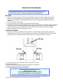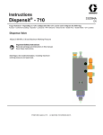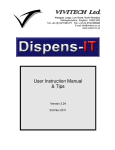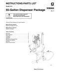
1
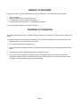
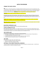
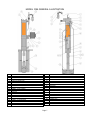
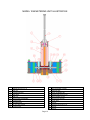
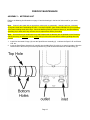
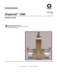
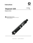
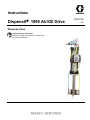
Instructions Dispensit 1095 Air/Oil Drive Dispense Valve Important Safety Instructions Read all warnings and instructions in this manual. Save these instructions. 332101A EN Quick Start Up Initial Start up Install the Air Oil unit in the normal upright position. It is not required to install material to the dispense valve in the initial startup. Metering rod up Air/Oil reservoir filed to line 70 psi dry non lubricated air supply Set the flow control knob set to “A” scale Adjust pneumatic flow control to almost closed (want slow travel during purge) Never over fill oil Never tip air oil cylinder when oil is in reservoir otherwise every time the solenoid cycles, oil will be atomized by the exhaust mufflers. Wet The System Connect the material feed and dispense valve Activate pneumatic solenoid on top of Air Oil unit either by using override control or using control circuit Lower metering rod to almost dead head position (no more than 4 inches of travel) Release solenoid control to allow metering rod to raise Check oil lever in reservoir Repeat lower / raise cycle until air is purged from Air Oil cylinder Once most air is purged from system adjust oil flow control to approximate speed of dispense Adjust pneumatic flow control to achieve fill rate - adjust for slowest refill possible so as to prevent metering rod cavitation (reintroducing air) Adjust the control system timer to control the Air Oil solenoid valve The higher the timer resolution the more accurate the dispense volume For minor bead adjustments, use the hydraulic flow control to achieve precise bead control Usually the control system is used to start and stop the bead. The on/off dispensing flow valve is tied into the starting and stopping of the Air Oil Occasionally it will be necessary to change the sequencing of the on/off valve to compensate for the uniqueness of the material handling characteristics. Quick Start Up con’t Cycle to purge air from system Activate pneumatic solenoid on top of Air Oil unit either by using override control or using control circuit Lower metering rod to almost dead head position (no more than 4 inches of travel) Release solenoid control to allow metering rod to raise Check oil lever in reservoir Repeat lower / raise cycle until air is purged from Air Oil cylinder Once most air is purged from system adjust oil flow control to approximate speed of dispense Adjust pneumatic flow control to achieve fill rate - adjust for slowest refill possible so as to prevent metering rod cavitation (reintroducing air) Sequence of Operation Metering rod in the home position (up) The oil reservoir is at its low level (lower black mark on the side of the upper chamber) To dispense ---- the solenoid is activated air is directed into the cap end of the cylinder forcing the oil residing in the cylinder’s rod end across the adjustable orifice in the flow control and back into the upper reservoir chamber. To refill ---- the solenoid shifts and pressurized air is forced into the upper reservoir chamber and oil is directed into the flow control and free flows around the orifice into the cylinder rod raising the metering rod. The exhausting cap end air is passed thru a pneumatic flow control to control the refill speed. To adjust the rate of dispense the knurl knob of the hydraulic flow control is rotated to achieve the desired speed. To adjust the refill rate the pneumatic flow control is similarly adjusted. DISPENSIT® MODEL 1095 DISPENSE VALVE OPERATING AND MAINTENANCE MANUAL General Information ........................................................................ 3 Safety Information ........................................................................... 3 Illustration References .................................................................... 3 General Accessories ....................................................................... 4 Sequence of Operation ................................................................... 4 Operation Illustration ..................................................................... 5 Setup Procedure ............................................................................. 6 Priming the Air/Oil Drive ............................................................... 6 Mounting Dispense Valve ............................................................. 6 On/Off Dispense Valve ................................................................. 6 Air Controller ................................................................................ 6 Air Lines........................................................................................ 6 Optional Cycle Detection Spool Sensors ...................................... 6 Model 1095 General Illustration ..................................................... 7 Operating Procedures .................................................................... 8 Dry Run ....................................................................................... 8 Loading & Priming ....................................................................... 8 Output Verification ....................................................................... 9 Daily Operation and Maintenance ............................................... 9 Operation Adjustments .................................................................. 10 Periodic Maintenance ..................................................................... 10 Refilling the Hydraulic Oil Reservoir ................................................ 10 Changing the Reclassifier Filter Element ......................................... 10 Disassemby – Metering Unit ............................................................ 11 Model 1095 Metering Unit Illustration .............................................. 12 Assembly – Metering Unit ................................................................ 13 Troubleshooting ............................................................................. 15 Model 1095 Recommended Spare Parts ....................................... 16 General Guidelines for O-rings and U-cup Seals .......................... 17 Warranty ........................................................................................... 18 Page 2 GENERAL INFORMATION The Model 1095 Series Metering Rod Positive Displacement Dispense Valve is designed for applications that require precise metering and volumetric consistency at a wide range of material inlet pressures. The 1095 operates with material supply pressures up to 1,200 psi (82.7 bar) or 400 psi (27.6 bar) for plastic spool models. Material viscosity dispensing capabilities range from very thin material to high viscosity pastes with viscosities in excess of 1,000,000 cps (1000 Pas). The Model 1095 series ships complete with the following: Model 1095 Dispense Valve Solenoid Valve (110 VAC) Air/Oil Drive Cylinder Oil Flow Control Metering Unit Mounting Bracket Seal Kit Optional Cycle Detection Sensors (comes with cycle detection option) Operating and Maintenance Manual SAFETY INFORMATION Only properly trained employees with a knowledge of the operations and safety warnings as set forth in this manual should use this product. Read all applicable manuals completely before operating. Note: The 1095 is shipped less the hydraulic oil in the Air/Oil cylinder. Add the oil before putting the 1095 into service. See “Priming the Air/Oil Drive” in the Setup Procedure section for details. WARNING: Do not exceed 100 psi (6.9 bar) pressure on the operating system. For 1095 valves with steel spools do not exceed 1200 psi (82.7 bar) material inlet pressure. For 1095 valves with plastic spools do not exceed 400 psi (27.6 bar) material inlet pressure. Higher pressures may cause a hazard or serious injury. Note: The minimum recommended pneumatic operating system pressure is 70 psi (4.8 bar) clean/dry air. Toxicity and flammability hazards depend upon the product being dispensed by this unit, and the user should take appropriate safety precautions as indicated on the MSDS of the product. Always wear safety glasses. ILLUSTRATION REFERENCES Throughout this manual you will find references by illustration item number to the illustrations in the manual. The references are indicated by parentheses around a number such as: (7). Illustrations represent typical valve configurations. The drawings for your exact model are inserted at the back of the manual and include the part numbers for ordering replacement parts. Page 3 GENERAL ACCESSORIES Liquid Control offers a full line of standard and custom accessories for your dispensing needs including: Valve Controllers Cartridge Retainers and Pressure Reservoirs Titan 200 High Pressure Cartridge Feed Systems Transfer Pump Feed Systems for 1, 5 and 55 gallon containers Consult your Dispensit dealer or the factory for details. SEQUENCE OF OPERATION The 1095 series Dispense Valve is a positive displacement valve. The sequence of operation of the system is as follows: 1. Material enters the valve through the material inlet port located on the adapter block and fills the spool and dispense cavities. This is the normal “ready” state. 2. The controller activates the dispense cycle. 3. The spool shifts to the dispense position, internally blocking the material inlet port and opening the dispense outlet. 4. The metering rod cycles, pushing material from the dispense cavity. 5. After the time delay set by the air controller the spool shifts again blocking the material outlet port and opening the material inlet port to refill the dispense cavity. At the same time the metering rod rises and the cavity fills. The system is again in the normal “ready” state. Page 4 OPERATION ILLUSTRATION Page 5 SETUP PROCEDURE PRIMING THE AIR/OIL DRIVE OIL The reservoir on the Air/Oil cylinder is not shipped wetted. When filling, be sure the unit is mounted firmly to the machine frame or other suitable surface. Remove the plug on the top of the unit and be sure that the metering rod is in the full down position (rod coupler is full down). Use new hydraulic oil with a viscosity of 100 SSU or lower. Pour the oil slowly into the port. WARNING: Do not use synthetic oils or oils with synthetic additives. WARNING: Do not overfill. Fill to the line MAX on the side of the unit. Reinstall the plug and set the air pressure to approximately 20 psi. Open the oil flow control fully and cycle the unit through the full range of travel until the air is entirely out of the lines (20 or 30 times). Check the oil level. If needed, release the air pressure, remove the plug and add oil. Reinstall the plug and increase air pressure to 70 psi. Caution: While cycling the unit use low pressure air as high pressure air may cause emulsion that results in frothing, which could carry over into the air lines and exhaust ports. Note: After adding oil, expect some oil escaping from the air valve exhaust for several cycles until the oil is blown off the internal screen inside the unit. MOUNTING DISPENSE VALVE Mount the 1095 in a vertical position only using the Mounting Bracket (25). ON/OFF DISPENSE VALVE Most applications require connection of the 1095 metering unit outlet to a high pressure On/Off dispense valve such as the Dispensit® Model 710 using a flexible hose that has a very low volumetric expansion ratio within the specified pressure ranges. We recommend stainless steel overbraided PTFE line. AIR CONTROLLER Operation of the 1095 requires a controller that provides the following: 3 A minimum of 0.5 SCFM (2/3 cm /s) of dry, unlubricated air at a minimum pressure of 70 psi (4.8 bar). Time delay capability to allow the valve to cycle. Independent air pressure regulators for material reservoir and valve operation. Logic and controls necessary to cycle the 110 volt Solenoid Valve. AIR LINES Install pneumatic supply lines to the Solenoid Valve. Minimum air pressure required is 70 psi (4.8 bar). Maximum air pressure is 100 psi (6.9 bar). OPTIONAL CYCLE DETECTION SPOOL SENSORS The spool sensors are magnetic reed switches and must be connected to an electrical control. An LED on the switch illuminates to indicate the shifting of the spool. Page 6 MODEL 1095 GENERAL ILLUSTRATION 1 2 3 4 5 6 7 8 9 10 10 11 12 13 14 15 16 17 18 19 MUFFLER,AIR,1/4NPT11 SOLENOID VALVE TEE, STREET ELBOW, STREET PUSH-IN CONNECTOR OIL FLOW CONTROL VALVE SUBPLATE OIL FLOW CONTROL VALVE BOLT KIT AIR/OIL CYLINDER TUBING, 1/4 OD, GREEN TUBING, 1/4 OD, YELLOW T-BLOCK METERING UNIT AIR/OIL CYLINDER FILL PORT PLUG ADAPTER,HEX ADAPTER,SWIVEL TUBING, .47 OD BRAIDED ADAPTER,HOSE ADAPTER,HEX NIPPLE,ADAPTER 20 21 22 23 24 25 26 27 28 29 30 31 32 33 34 35 36 37 38 Page 7 AIR FLOW CONTROL VALVE RETRACT OIL LINE RETRACT OIL PORT ELBOW NIPPLE ELBOW,STREET MOUNTING BRACKET ADAPTER,SWIVEL, BUSHING ELBOW, SCREW,SHS,#8-32 X 3/16 SCREW,SHC,1/4-20 X 3-3/4 SCREW,HHC ADAPTER NIPPLE, HEX OIL RECLASSIFIER/MUFFLER SCREW,SHC BACKING PLATE SLUG,PTFE WASHER OPERATING PROCEDURES A Dry Run demonstrates the valve’s controls and dispensing steps. It also verifies that the valve is working correctly before you load materials. DRY RUN 1. Attach the pneumatic supply lines from the air line fittings on the valve to the air supply outlets on the air controller. Factory supplied air lines and fittings are color-coded yellow for the air supply to initiate the dispense cycle and green for the refill shuttle and match the color-coding on Dispensit® 4100 series air controllers. 2. Turn on the electric and air supply. 3. Set the air pressure to 70 psi (4.8 bar) on the system pressure gauge. 4. Momentarily activate the controller’s Dispense Valve cycling control switch. The 1095 valve should go through a complete cycle and cause a slight fluctuation in the system pressure gauge. If the valve is equipped with optional cycle detection the illumination of the LED’s on the spool reed sensors verifies spool shifting. 5. When this happens, the system installation is correct. LOADING & PRIMING 1. Fill the oil cups with a compatible lubricant (suitable for use with material). Use them when dispensing a material that air cures easily. They are designed to act as reservoirs for compatible material to help prevent having material cure on movable shafts. Cured material can cause premature wear of the seals. 2. If not removed, remove the material line from the inlet port of the valve. 3. Prime the material line. 4. Extend the valve to the Dispense Cycle(refer to Sequence of Operation). 5. Install the material line to the inlet port of the valve. 6. Increase the material inlet pressure for loading. Recommended Material Supply Pressure Minimum - 20 psi (1.4 bar) For Plastic Spools Maximum - 400 psi (27.6 bar) For Steel Spools Maximum - 1200 psi (82.7 bar) The above settings depend on the cycle rate and viscosity of the material. 7. Perform the loading sequence of the valve until air free material is visible. OPERATING PROCEDURES Output verification is a simple procedure where individual samples of material are collected, weighed, and compared for desired output. We recommend that you perform output verification at least once a day, and if the machine is used in production for more than one shift, then once a shift. OUTPUT VERIFICATION 1. Position a clean container under the valve outlet. 2. Set the stroke of the metering rod to desired shot size. 3. Weigh three small empty cups and label. 4. Take a purge shot into an unweighed empty cup. 5. Dispense ten shots into the first labeled cup. 6. Proceed in the same manner with the other labeled cups. 7. Reweigh all three cups and record results (results will be ten times desired shot size). If shot weights are inconsistent an adjustment of the material pressure and/or Operation Adjustments may be necessary. DAILY OPERATION & MAINTENANCE Before operating, perform all Daily maintenance listed below. Also, complete all loading, priming, and output verification procedures. If there are any problems in getting started, refer to the Troubleshooting section or call Technical Service at (330) 494-1313. MATERIAL RESERVOIR Check material levels and refill as necessary. OIL CUPS Fill with lubrication suitable for use with material. EXTERIOR Check and clean the exterior of the valve. Page 9 OPERATION ADJUSTMENTS Adjust the 1095 Valve for proper operation as follows (refer to the 1095 General Illustration on page 7): 1. Make sure that all the connections are in place. 2. Dry cycle the 1095 Valve through its complete cycle and make these adjustments as needed. 3. The Air Flow Control Valve (20) controls how fast the refill stroke moves. Adjust it so that the stroke is smooth and slow enough to refill completely without cavitating. 4. The Oil Flow Control Valve (7), the Vickers knob with key lock on the front, controls how fast the dispense stroke moves. Adjust it so that this stroke is smooth and does not cause the material to dispense in an uncontrolled manner. The dispense flow should be adjusted to match the speed of the dispensing tip. Note: The key is used to lock and unlock the Vickers knob to prevent unauthorized adjustment. 5. Connect the material for dispensing. Position a container to catch the dispensed material. Cycle the unit until you are getting consistent dispensing (no inconsistencies or air in the dispensed material, symmetrical deposit shape). 6. Weigh or measure a sample of the dispensed material to see if the volume is correct. 7. Continue to observe the cycling of the unit to see if the material has caused any change in the dispense and reload strokes. If necessary, make minor adjustments to the flow controllers to restore smooth operation. 8. To adjust the volume, use the logic controller to regulate how long air pressure is supplied to the dispensing unit, and adjust the rate of flow using the Oil Flow Control Valve (7). 9. Repeat the above steps until you obtain the correct stroke and volume. 10. Adjust the operation timing so that the 1095 Valve is able to finish its dispense before the Dispense Head needle moves away from the part. PERIODIC MAINTENANCE REFILLING THE HYDRAULIC OIL RESERVOIR Refer to the 1095 General Illustration on page 7. Oil Selection: Use new hydraulic oil with a viscosity of 100 SSU (ISO 22) such as Mobil Velocite #10 or any SAE 10 weight rust (R) and oxidation (O) inhibited motor oil. WARNING: Do not use synthetic oils or oils with synthetic additives. 1. When the hydraulic oil falls below the minimum level indicated on the Air/Oil Cylinder with the cylinder rod fully extended it requires refilling. 2. When refilling the hydraulic reservoir, place the Air/Oil cylinder in the retracted position (cylinder rod inside the the Air/Oil Cylinder), disconnect the air supply, remove the Air/Oil fill port plug (13), and slowly fill the Air/Oil cylinder to the maximum fluid level. Install and tighten Air/Oil fill port plug (13) securely. CHANGING THE RECLASSIFIER FILTER ELEMENT Refer to the 1095 General Illustration on page 7. 1. The 1095 is equipped with an Oil Reclassifier (34) to collect hydraulic oil mist that may exhaust from the solenoid valve during operation. If oil mist begins to emerge the filter is full. Remove it and change the filter element. 2. The Oil Reclassifier (34) has a drain outlet on the bottom. If your application generates an undue amount of oil mist you may run a drain line from this outlet. Page 10 PERIODIC MAINTENANCE DISASSEMBLY – METERING UNIT Refer to the 1095 General Illustration on page 7 to remove the metering unit from the 1095. 1. Note: This step is only for models with cycle detection sensors. Disconnect the electrical power from the cycle detection sensors. Note the position of the sensors, then remove them by loosening the set screws and sliding them out carefully. 2. Turn off the material inlet pressure to the 1095. 3. Cycle the valve a few times to remove residual material pressure. 4. Turn off the air pressure to the 1095. 5. Disconnect the air line Tubing (10) from the lower Push-In Connectors (5). 6. Remove the material inlet and outlet lines. 7. Remove any fluid from the oil cups. 8. Remove the two Screws (30) that extend through the Backing Plates (36) and Metering Unit (12). Carefully slide the metering rod head out of the T-Block (11) to remove the Metering Unit (12). Refer to the 1095 Metering Unit Illustration on the next page for the remaining steps. 9. At the top of the valve, remove the two Screws (1) and remove the Top Cap (2). Remove the Metering Rod (8) if it was not previously removed. 10. Remove the Posipak Seal (7) from the Top Cap (2). Remove the O-ring (21). 11. Remove the four Screws (14) and the End Cap (5) on each side of the valve. 12. Remove the two Spool Shift Pistons (16) from the End Caps (5). They should come out easily but if not use low pressure (less than 2 psi or .1 bar) air at the Push-In Connector (13) to move them. Remove the U-cup seals (17) from the Spool Shift Pistons (16). 13. Remove the Dispense Sleeve (3) from the Main Body (4). If the sleeve is plastic and does not slide out readily then you can thread an appropriately sized tap into it a turn or two and pull it out. A few turns of threads in the plastic will do no harm but wear or cracking will mean that you must replace it. Keep track of which end of the sleeve you tapped into as you will want it at the top again upon reassembly. 14. Remove the Screws (19) that hold the Oil Cup Seal Plates (9) to each side of the Main Body (4). The Seal Retainer Washers (11), and the Posipak Seals (10 and 7) will come off with the Oil Cup Seal Plates. Remove those seals and the O-rings (20). 15. Push the Spool/Sleeve Assembly (6) out with a finger. If it does not slide out, tap it gently using a wood or plastic dowel. A worn spool and sleeve assembly must be replaced with a new (matched) assembly. If you are rebuilding multiple valves be sure to keep the spools and sleeves matched. 16. Remove the O-rings (18) from the Spool/Sleeve Assembly (6). 17. Check the contents of the seal kit versus what you removed then discard the old items. Page 11 MODEL 1095 METERING UNIT ILLUSTRATION 1 SCREW,SHC,#10-32 X 7/8 11 SEAL RETAINER WASHER 2 TOP CAP 12 POSIPAK SEAL 3 DISPENSE SLEEVE 13 PUSH-IN CONNECTOR 4 MAIN BODY 14 SCREW,RHM,#10-32 X 2-1/2 5 END CAP 15 PLUG,SOCKET,1/8 NPT 6 SPOOL/SLEEVE ASSEMBLY 16 SPOOL SHIFT PISTON 7 POSIPAK SEAL 17 U-CUP SEAL 8 METERING ROD 18 O-RING 9 OIL CUP SEAL PLATE 19 SCREW,SHC,#10-32 X 1-1/4 10 POSIPAK SEAL 20 O-RING 21 O-RING Page 12 PERIODIC MAINTENANCE ASSEMBLY – METERING UNIT Refer to the Metering Unit Illustration on page 12 and the drawings in the back of this manual for your exact model. Note: Clean all valve parts with an appropriate solvent prior to reassembly. Always install new, lubricated O-rings and seals when assembling the valve. Use Krytox 203GPL (part number 84/0200-K3/11) for lubricating valve parts including seals and o-rings. Check the Metering Rod (8), Dispense Sleeve (3), and Spool/Sleeve Assembly (6) for wear and if they are worn secure replacements before proceeding. Note: Use caution as you install new U-cup and Posipak seals so that they are not pinched or torn. Do this by making sure they are lubricated, and by tucking the lips of the seal inward before uniformly pushing them into position. 1. Install four lubricated O-rings (18) onto the Spool/Sleeve Assembly (6). Lubricate the Spool O.D. and Sleeve O.D. too. 2. Insert the Spool/Sleeve Assembly (6) carefully into the Main Body (4) rocking it to ease it into place. Align the bottom holes of the Sleeve piece of the Spool/Sleeve (6) with the inlet/outlet holes of the Main Body (4). Page 13 PERIODIC MAINTENANCE ASSEMBLY – METERING UNIT Install the Seal Plate Cups on the Main Body 3. Install a lubricated O-ring (20) on the left side of the Main Body (4) next to the sleeve part of the Spool/Sleeve Assembly (6). 4. Install lubricated Posipak Seals (7 and 10) in the left Seal Plate Cup (9) so that the O-ring side of both Posipaks will be facing the Main Body (4). Be sure to tuck the lip of the Posipak into its cavity to avoid tearing it. 5. Position the left Seal Cup Plate (9) with the oil cup upwards and slide it over the Spool part of the Spool/Sleeve Assembly (6) with the counterbore for the Seal Retainer Washer (11) facing out. Slide the Seal Retainer Washer (11) over the Spool and install two Screws (19). 6. Repeat steps 3, 4 and 5 for the right side Seal Plate Cups. Mount the Valve End Caps to the Seal Plate Cups 7. Install a lubricated U-cup Seal (17) onto the left Spool Shift Piston (16) with lip side out as shown. Lubricate the bore in the End Cap (5). Slide the piston into the left End Cap (5) tucking the lip of the seal into the End Cap carefully. 8. Install the Piston/End Cap onto the left Oil Cup Seal Plate (9) using four Screws (14). Tighten the screws in a cross pattern gradually to prevent binding due to misalignment (like you would tighten lug nuts on a car tire). 9. Push the Spool into the left side until it contacts the piston. 10. Repeat steps 7 and 8 for the right side. Install the Dispense Sleeve, Top Cap and Metering Rod 11. Lubricate the dispense sleeve bore in the Main Body (4). Insert the Dispense Sleeve (3) into the Main Body (4). Check for threads that may be in the inside of the sleeve due to tapping during removal and make sure these are at the top. 12. Install the lubricated O-ring (21) around the Dispense Sleeve (3). 13. Install the lubricated Posipak Seal (12) into the Top Cap (2). Be sure to tuck the lip of the Posipak into its cavity to avoid tearing it. 14. Insert the Metering Rod (8) through the Top Cap (2) and Posipak Seal (12) carefully. 15. Using the projecting Metering Rod (8) as a guide into the Dispense Sleeve (3), position the Top Cap (2) on the Main Body (4). 16. Install the two Screws (1) through the Top Cap (2) and into the Main Body (4). Tighten the screws in a cross pattern gradually to prevent binding due to misalignment (like you would tighten lug nuts on a car tire). Install the Metering Unit on the 1095 Valve Refer to the 1095 General Illustration on Page 7 for these steps. 17. Insert the head of the metering rod fully into the T-Block (11) and slide the Metering Unit (12) into position. 18. Position the Backing Plates (36) and install the two screws (30) to secure the Metering Unit (12) to the 1095 Mounting Bracket (25). 19. Connect the air line Tubing (10) to the Push-In Connectors (5). 20. If your valve has cycle detection, slide the cycle detection sensors into the slots on the end caps and secure with the set screws. Do not overtighten the set screws as the sensors may be damaged. 21. Connect the material inlet and outlet lines. 22. Perform the Dry Run, Loading & Priming and Output Verification procedures. Perform Operation Adjustment procedures if required. Page 14 TROUBLESHOOTING Review the symptoms below for operating difficulties. With each problem there are one or more possible causes to investigate. NOTHING HAPPENS - If absolutely nothing happens when trying to cycle the 1095, check the electric and pneumatic power. VALVE CYCLES, NOTHING DISPENSED - First, if there is an On/Off valve downstrean of the 1095, make sure the On/Off Dispense Valve is sequencing properly with the metering unit. Try to purge the metering unit; this should fix most situations. Then, if nothing dispenses, check to see that there is enough air pressure to the reservoir. Perhaps material has “set up” in the reservoir or supply hoses; examine and clear or replace as necessary. Refer to the Operation and Periodic Maintenance Procedures in the appropriate manuals. IRREGULAR VOLUME DISPENSED - Faulty material will cause irregular dispensing. The material must be a smooth (homogeneous) mixture, without any air trapped in it. A second cause could possibly be that the material is not filling the metering rod chamber fully and in time. Check the reservoir pressure as it may be too low for the type of material being dispensed and/or the cycle time may be too fast. Cycle time is a function of 1. adequate air supply pressure, 2. the duration of supply signal, and 3. the stroke speed. To adjust, follow the directions found in the Operation Adjustments section of this manual. SLOW OR SLUGGISH CYCLE - This may be due to inadequate lubrication of the piston walls. Apply a very thin film of a compatible lubricant to the outside diameter surfaces of the pistons and the U-seals and reassemble. This should restore smooth and consistent operation. Another cause may be misalignment between the Metering Rod and the Metering Body. Loosen the two Screws (30) that hold the Metering Unit (12) to the Mounting Bracket (25). Power the metering rod to its full down position and tighten the Retaining Nuts. The unit is now realigned. ON/OFF DISPENSE VALVE DROOLS OR OOZES - This can result from air trapped in the material being dispensed, wear on the valve seat of the On/Off valve, or a worn seal in the 1095 as well as the On/Off valve, or the On/Off Valve is out of sequence. Check the sequence and refer to the On/Off Dispense Valve Manual. Page 15 MODEL 1095 RECOMMENDED SPARE PARTS Note: These parts are routine supply items or wear parts not covered by warranty for normal wear. Quantity 1 1 1 1 1 A/R Description SEAL KIT,1095 DISPENSE SLEEVE METERING ROD SPOOL/SLEEVE ASSEMBLY RECLASSIFIER FILTER ELEMENT KRYTOX 203GPL ASSEMBLY LUBRICANT Page 16 Part Number see assembly drawing for part number see assembly drawing for part number see assembly drawing for part number see assembly drawing for part number 82/0021-E/11 84/0200-K3/11 GENERAL GUIDELINES FOR O-RINGS AND U-CUP SEALS Sizes and materials of construction for O-rings and U-cup seals are selected by Liquid Control based on compatibility with the chemicals to which they will be exposed. Solvents that may remove residual chemicals often have negative effects on the mechanical properties of O-rings and seals. O-Ring Guidelines Always replace an O-ring with the identical one in size, durometer hardness, type and material of construction. Always be alert to the location and size of each O-ring as many look alike and be careful not to mix them. Often similar sizes may be used in various locations on the equipment and if replaced incorrectly, the equipment may not function properly. Refer to the Machine Operation and Service Manual for the correct part number of all O-rings used throughout the equipment and replace them with factory approved parts only. Re-use of O-rings is not recommended. Only re-use O-rings as a last resort. If you must re-use them, be sure that they are clean, have no cuts or flat spots and contain NO foreign material. Also, be sure not to soak them in solvent for extended periods as this can cause deterioration of the O-ring. Always replace O-rings that are cut, nicked, or distorted in shape or cross-section. Always apply a very thin film of Krytox 203GPL lubricant, item 84/0200-K3/11, to the entire surface of the oring before installation. Avoid excessive lubrication. If installing O-rings over threads on a shaft or across sharp edges, roll or push the O-ring carefully into place being careful to avoid cutting or nicking it. Avoid stretching the O-ring too much as it may not return to the proper size. Do not use any sharp tools or objects to install O-rings U-cup Seal Guidelines Always replace a U-cup seal with the identical one in size, durometer hardness, type and material of construction. Always be alert to the location and size of each U-cup seal as many look alike and be careful not to mix them. Often similar sizes may be used in various locations on the equipment and if replaced incorrectly, the equipment may not function properly. Refer to the Machine Operation and Service Manual for the correct part number of all U-cups used throughout the equipment and replace them with factory approved parts only. Always apply a very thin film of Krytox 203GPL lubricant, item 84/0200-K3/11, to the inner and outer lips of the seal before installation. Re-use of U-cup seals is not recommended. Only re-use U-cups as a last resort. If you must re-use them, be sure that they are clean, have no cuts or flat spots and contain NO foreign material. Also, be sure not to soak them in solvent for extended periods as this can cause deterioration of the seal. Always replace U-cups that are cut, have flat spots, are distorted in shape or are damaged in any manner. Always be alert to the proper orientation of the sealing lips and re-install them in the same direction as shown on the specific equipment assembly drawing. The U-cup seals are intended to seal in only one direction and if installed incorrectly, chemical leakage through the U-cup can occur. Whenever possible, push the back side of the seal over the shaft to protect the inner and outer lips. If this is not possible, carefully tuck the lip in to avoid rolling it back or cutting it. If installing over sharp edges, slide the seal carefully into place to avoid cutting it. Do not use any sharp tools or objects to install U-cups. Page 17 Graco warrants all equipment referenced in this document which is manufactured by Graco and bearing its name to be free from defects in material and workmanship on the date of sale to the original purchaser for use. With the exception of any special, extended, or limited warranty published by Graco, Graco will, for a period of twelve months from the date of sale, repair or replace any part of the equipment determined by Graco to be defective. This warranty applies only when the equipment is installed, operated and maintained in accordance with Graco’s written recommendations. This warranty does not cover, and Graco shall not be liable for general wear and tear, or any malfunction, damage or wear caused by faulty installation, misapplication, abrasion, corrosion, inadequate or improper maintenance, negligence, accident, tampering, or substitution of nonGraco component parts. Nor shall Graco be liable for malfunction, damage or wear caused by the incompatibility of Graco equipment with structures, accessories, equipment or materials not supplied by Graco, or the improper design, manufacture, installation, operation or maintenance of structures, accessories, equipment or materials not supplied by Graco. This warranty is conditioned upon the prepaid return of the equipment claimed to be defective to an authorized Graco distributor for verification of the claimed defect. If the claimed defect is verified, Graco will repair or replace free of charge any defective parts. The equipment will be returned to the original purchaser transportation prepaid. If inspection of the equipment does not disclose any defect in material or workmanship, repairs will be made at a reasonable charge, which charges may include the costs of parts, labor, and transportation. . Graco’s sole obligation and buyer’s sole remedy for any breach of warranty shall be as set forth above. The buyer agrees that no other remedy (including, but not limited to, incidental or consequential damages for lost profits, lost sales, injury to person or property, or any other incidental or consequential loss) shall be available. Any action for breach of warranty must be brought within two (2) years of the date of sale. . These items sold, but not manufactured by Graco (such as electric motors, switches, hose, etc.), are subject to the warranty, if any, of their manufacturer. Graco will provide purchaser with reasonable assistance in making any claim for breach of these warranties. In no event will Graco be liable for indirect, incidental, special or consequential damages resulting from Graco supplying equipment hereunder, or the furnishing, performance, or use of any products or other goods sold hereto, whether due to a breach of contract, breach of warranty, the negligence of Graco, or otherwise. The Parties acknowledge that they have required that the present document, as well as all documents, notices and legal proceedings entered into, given or instituted pursuant hereto or relating directly or indirectly hereto, be drawn up in English. Les parties reconnaissent avoir convenu que la rédaction du présente document sera en Anglais, ainsi que tous documents, avis et procédures judiciaires exécutés, donnés ou intentés, à la suite de ou en rapport, directement ou indirectement, avec les procédures concernées. For the latest information about Graco products, visit www.graco.com. 612-623-6921 contact your Graco distributor or call to identify the nearest distributor. 1-800-746-1334 330-966-3006 • Minneapolis Belgium, China, Japan, Korea • www.graco.com •