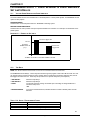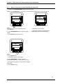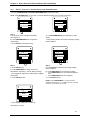
1
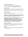
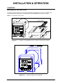
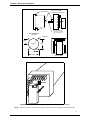
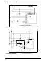
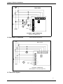
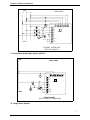
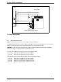
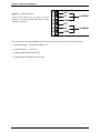
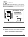
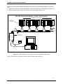
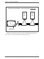
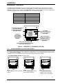
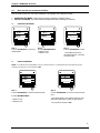
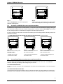
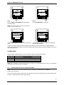
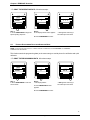
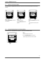
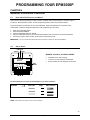
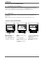
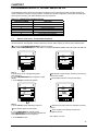
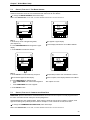
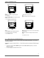
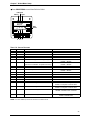
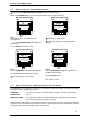
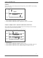
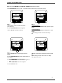
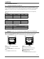
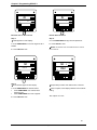
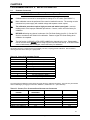
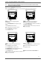
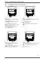
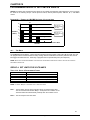
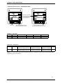
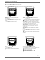
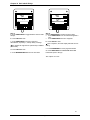
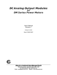
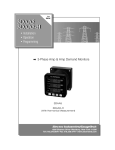
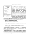
EPM 3000P THREE-PHASE DIGITAL VOLT/AMPS MONITOR EPM 3000P –F THREE-PHASE VOLTS/AMPS/FREQUENCY MONITOR Instruction Manual g GE Industrial System NORTH AMERICA GE Industrial Systems, 41 Woodford Avenue, Plainville, CT 06062 Internet: http: www.geindustrial.com All Rights Reserved. Printed in the United States of America. NORTH AMERICA GE Industrial Systems, 41 Woodford Avenue, Plainville, CT 06062 Internet: http: www.geindustrial.com Customer Service and Support Customer service and support is available 24 hours a day, 7 days a week. Please have the model, serial number and a detailed problem description available. If the problem concerns a particular reading, please have all meter readings available. For customer or technical assistance, call: 1-888-GE4SERVICE (1-888-434-7378). Product Warranty GE warrants all products to be free from defects in material, workmanship and title and will be of the kind and quality specified in GE’s written description in the manual. The foregoing shall apply only to failures to meet said warranties which appear within one year from the date of shipping. During the warranty period, GE will, at its option, either repair or replace any product that proves to be defective. Limitation of Warranty This warranty does not apply to defects resulting from unauthorized modification, misuse or use for any reason other than electrical power monitoring. OUR PRODUCTS ARE NOT TO BE USED FOR PRIMARY OVER-CURRENT PROTECTION. ANY PROTECTION FEATURE IN OUR PRODUCTS IS TO BE USED FOR ALARM OR SECONDARY PROTECTION ONLY. THIS WARRANTY IS IN LIEU OF ALL OTHER WARRANTIES, EXPRESSED OR IMPLIED, INCLUDING ANY IMPLIED WARRANTY OF MERCHANABILITY OR FITNESS FOR A PARTICULAR PURPOSE. GE SHALL NOT BE LIABLE FOR ANY PENAL, INDIRECT, SPECIAL OR CONSEQUENTIAL DAMAGES ARISING FROM ANY AUTHORIZED OR UNAUTHORIZED USE OF ANY GE PRODUCT. LIABILITY SHALL BE LIMITED TO THE ORIGINAL COST OF THE PRODUCT SOLD. Statement of Calibration Our instruments are inspected and tested in accordance with specifications published by an independent testing facility. The accuracy and a calibration of our instruments are traceable to the National Institute of Standards and Technology through equipment that is calibrated at planned intervals by comparison to certified standards. Disclaimer The information presented in this publication has been carefully checked for reliability; however, no responsibility is assumed for inaccuracies. The information contained in this document is subject to change without notice. GE Industrial Systems i TABLE OF CONTENTS INSTALLATION & OPERATION CHAPTER 1 MECHANICAL INSTALLATION CHAPTER 2 Installation of the EPM3000P with K-110 Option for limited space conditions Standard Installation of the EPM3000P Standard Cutout of EPM3000P Communication Converter Installation or DC Output ELECTRICAL INSTALLATION Section 2.1 2.2 2.3 2.4 2.5 Connecting the Current Circuit Connecting Voltage Circuit of Potential Transformer Selecting the Voltage Fuses Connection to the Main Power Supply Electrical Connection Installation 3-Phase, 3-Wire Delta with Direct Voltage and CTs 3-Phase, 3-Wire Open Delta with 2 CTs and 2 PTs 3-Phase, 3-Wire Open Delta with 3 CTs and 2 PTs 3-Phase, 4-Wire Wye with Direct Voltage and CTs 3-Phase, 4-Wire Wye with CTs and PTs Single Phase System Dual Phase System 2.6 Relays and Protection CHAPTER 3 COMMUNICATION INSTALLATION Section 3.1 RS-232C 3.2 RS-485 CHAPTER 4 Section 4.1 4.2 4.3 4.4 4.5 4.6 4.7 4.8 1 1 1 2 2 3 3 3 3 3 4 5 5 6 6 7 7 8 8 10 10 10 EPM3000P: OVERVIEW 13 Accessing Max/Min Values Resetting Values Accessing the LM1/LM2 Set Limits Voltage Phase Reversal and Imbalance Printing Operating Data Printing Programming Data Accessing LED Test Accessing Firmware Versions 13 14 15 15 16 17 18 18 GE Industrial Systems ii TABLE OF CONTENTS PROGRAMMING CHAPTER 5 Section 5.1 5.2 5.3 5.4 CHAPTER 6 GENERAL PROCEDURE OVERVIEW 19 How to Use This Portion of the Manual Switch Packs Programming Mode Entry Standard Numeric Data Entry 19 19 20 20 ENTERING THE PROGRAMMING MODE 21 Section 6.1 Checksum Error - Protective Mechanism 6.2 Password Entry CHAPTER 7 Section 7.1 7.2 7.3 7.4 7.5 7.6 CHAPTER 8 PROGRAMMING GROUP 0: GLOBAL METER SETUP 22 The Integration Interval The Meter Address Communication Baud Rate System Configuration Programming Procedure Time Delay For Relays 1 & 2 22 23 23 24 26 26 PROGRAMMING GROUP 1 29 Section 8.1 Scale Selections & Full Scale Settings 8.2 Full Scale Settings, Volt & Amp Channels, Volt & Amp Decimal Placement CHAPTER 9 PROGRAMMING GROUP 2: METER CALIBRATION Section 9.1 Standard Calibration 9.2 High End Calibration of Voltage Channels, High & Low End Calibration of Amperage Channels CHAPTER 10 PROGRAMMING GROUP 4: SET LIMITS & RELAYS 29 29 31 31 32 34 34 Section 10.1 Trip Relay CHAPTER 11 PROGRAMMING GROUP 7: PHASE REVERSAL & PHASE IMBALANCE SET LIMITS/RELAYS Section 11.1 11.2 11.3 11.4 21 21 Voltage Phase Reversal & Phase Imbalance Trip Relay Voltage Phase Reversal Detection Percentage Voltage Phase Imbalance CHAPTER 12 EXITING THE PROGRAMMING MODE GE Industrial Systems 38 38 38 39 40 41 iii INSTALLATION & OPERATION CHAPTER 1 MECHANICAL INSTALLATION The following diagrams display the various possible EPM3000P and EPM3000P-F mechanical installations and Communication Converter installation. All illustrations are of the EPM3000P with notes on the F Model. NOTE: ALL MEASUREMENTS ARE IN INCHES. 36" CABLE 3.00 0.80 AC VOLTS A B C A B C N N N B C A 4.50 SQ. AC AMPS A B C N MAX MIN MAX/MIN PRINT LIMITS PROG LM1 VOLTS AMPS 0.336 LM2 2.45 PHASE 2.425 NEXT 4.375 (4) 8-32 SCREWS SQ. Diagram 1.1 0.714 5.00 0.890 Installation of the EPM3000P with K-110 Option for limited space conditions. 4.50 SQ. AC VOLTS A B C A B C N N N B C A AC AMPS 2.0 A B C N MAX MIN MAX/MIN PRINT LIMITS PROG LM1 VOLTS 4.375 SQ. Diagram 1.2 AMPS LM2 3.0 PHASE NEXT 0.890 Standard Installation of the EPM3000P. 1 GE Industrial Systems Chapter 1 Mechanical Installation SIDE VIEW (4) 8-32 SCREWS FIRST PUT (16) PIN CONNECTOR TOGETHER. 0.80 (2) 8-32 SCREWS WILL LINE UP WITH 2 PEMS ON THE BACK PLATE. RECOMMENDED CUTOUT 0.198 DIA. 1.6875 4.0 DIA. 3.375 1.6875 3.375 BACK VIEW Diagram 1.3 Standard cutout for EPM3000P. W Port Diagram 1.4 Optional Communication Converter or DC Output Module Installation NOTE: CAREFULLY LINE UP THE GUIDE SCREW AND 8 PIN PORT CONNECTOR TO PREVENT PINS FROM BREAKING. 2 GE Industrial Systems CHAPTER 2 ELECTRICAL INSTALLATION 2.1 CONNECTING THE CURRENT CIRCUIT The cable used for the current should be installed at 600V AC minimum. The cable connector should be rated at 6 Amps or greater, and it should have a cross-sectional area of 16 AWG. The current transformers should be mounted as close as possible to the meter. The following table gives the maximum recommended distances for various CT sizes, assuming the connection is made via 16 AWG cable. CT SIZE (VA) MAXIMUM DISTANCE (CT TO EPM3000P) 2.5 VA 5.0 VA 7.5 VA 10.0 VA 15.0 VA 30.0 VA 10 FEET 15 FEET 30 FEET 40 FEET 60 FEET 120 FEET WARNING: DO NOT LEAVE SECONDARY OF CT WHEN PRIMARY CURRENT IS FLOWING. THIS MAY CAUSE HIGH VOLTAGE, WHICH OVERHEATS THE SECONDARY OF THE CT. SECONDARY OF THE CT. 2.2 IF THE CT IS NOT CONNECTED, PROVIDE A SHORTING BLOCK ON THE CONNECTING VOLTAGE CIRCUIT OF POTENTIAL TRANSFORMER For proper operation, the voltage connection must be maintained. If an error occurs, such as mistaking Line A for Line B, a PH message appears, indicating a Phase Reversal (see Phase Imbalance and Reversal). The cable required to terminate the voltage sense circuit should have an insulation rating greater than 600V AC and a current rating greater than 0.1 A. 2.3 SELECTING THE VOLTAGE FUSES We recommend using fuses, although connection diagrams do not show them. Slow blow, 200 mA rating fuses should be used. The maximum voltage EPM3000P can handle 150V phase to neutral. If Suffix -G is added to the model number, the maximum voltage to be used is 300V phase to neutral. 2.4 CONNECTION TO THE MAIN POWER SUPPLY The EPM3000P requires a separate power supply connection. Listed are the 5 different power supply options and corresponding. NOTE: FOR DC-POWERED UNITS POLARITY MUST BE OBSERVED. AN EARTH TO GROUND CONNECTION TO CHASSIS IS MANDATORY FOR NORMAL OPERATION (TERMINAL 3). DO NOT GROUND THE UNIT THROUGH THE NEGATIVE OF THE DC SUPPLY. SEPARATE GROUNDING IS REQUIRED. POWER SUPPLY OPTIONS SUFFIXES CURRENT 120V AC 240V AC 24V DC 48V DC 125V DC NO SUFFIX A D D1 D2 .1 AAC .05 AAC .5 ADC .25 ADC .1 ADC 3 GE Industrial Systems Chapter 2 Electrical Installation 2.5 ELECTRICAL CONNECTION INSTALLATION Choose the diagram that best suits your application and maintain the polarity. Follow the outlined procedure to verify correct connection. NOTE: THE NEUTRAL READING IS CALCULATED FROM THE SUM OF THE 3 PHASES OF CURRENT. HIGH NEUTRAL CURRENT INDICATES REVERSE CT POLARITY. LISTING OF CONNECTION DIAGRAMS NOTE: SEE PHASE REVERSAL IF A MESSAGE OF PH APPEARS AFTER INSTALLATION. I Three-Phase, Three-Wire System Delta with Direct Voltage and CTs. II Three-Phase, Three-Wire Open Delta with two CTs and two PTs. (Open Delta System Installation should only be used if the electrical system is a 3-wire OPEN DELTA. Open Delta can be enabled or disabled in Programming Group 0, Function 3.) III Three-Phase, Three-Wire Open Delta with three CTs and two PTs. (Open Delta System Installation should only be used if the electrical system is a 3-wire OPEN DELTA. Open Delta can be enabled or disabled in Programming Group 0, Function 3.) IV Three-Phase, Four-Wire System Wye with Direct Voltage and CTs. V Three-Phase, Four-Wire System Wye with CTs and PTs. VI Single Phase System VII Dual Phase System 4 GE Industrial Systems Chapter 2 Electrical Installation A LINE B BACK VIEW C 7 8 9 10 11 12 13 6 PORT 5 4 3 CONTROL LOAD POWER + 2 L1 - 1 L 3-PHASE, 3-WIRE DELTA WITH DIRECT VOLTAGE AND CTs I. Three Phase System A LINE B BACK VIEW C 7 8 9 10 11 12 13 6 5 PORT 4 3 CONTROL LOAD + 2 L1 - 1L POWER 3-PHASE, 3-WIRE OPEN DELTA WITH 2 CTs AND 2 PTs II. Open Delta PT Connection Special programming required. 5 GE Industrial Systems Chapter 2 Electrical Installation A LINE B BACK VIEW C 7 8 10 11 9 12 13 6 PORT 5 4 3 + 2 L1 - 1L POWER LOAD 3-PHASE, 3-WIRE OPEN DELTA WITH 3 CTs AND 2 PTs III. Open Delta PT Connection N LINE A B Special programming required. BACK VIEW C 7 8 9 10 11 12 13 6 5 PORT 4 3 CONTROL LOAD POWER + 2 L1 - 1 L 3-PHASE, 4-WIRE WYE WITH DIRECT VOLTAGE AND CTs IV. Three Phase System 6 GE Industrial Systems Chapter 2 Electrical Installation LINE N A B BACK VIEW C 7 8 9 10 11 12 13 6 PORT 5 4 3 + 2 L2 - 1 L1 POWER LOAD 3-PHASE, 4-WIRE WYE WITH CTs AND PTs V. Three Phase System Wye System with PTs LINE A BACK VIEW 7 8 9 10 11 12 13 6 5 PORT 4 3 LOAD POWER + 2 L2 - 1 L1 SINGLE-PHASE WITH CT AND PT CONNECTION VI. Single-Phase System 7 GE Industrial Systems Chapter 2 Electrical Installation LINE N A BACK VIEW B 7 8 9 10 11 12 13 6 5 PORT 4 3 POWER LOAD + 2 L2 - 1 L1 DUAL-PHASE WITH CTs AND Direct Voltage VII. Dual-Phase System 2.6 RELAYS AND PROTECTION NOTE: THIS SECTION IS APPLICABLE ONLY IF THE -NL RELAY OPTION WAS ORDERED. The EPM3000P allows the user to access a variety of relay options through the programming mode. The relay option package consists of two relays, which can be dedicated to alarm or communication (or both). TIME DELAY: Sets off the alarm, alerting the user that an out-of-limits condition occurred during the defined time limit. The time delay can be programmed for any desirable duration. If the relays are dedicated to communication, there are two different modes: Lock ON Lock OFF Relay will not be affected by any alarm condition. Relay will not be affected by any alarm condition. If the relays are used for communication and alarm, there are four different modes: Lock ON Lock OFF Free ON Free OFF Relay stays on regardless of any alarm condition. Relay stays off regardless of any alarm condition. Relay turns on unless other conditions force it off. Relay turns off unless other conditions force it on. 8 GE Industrial Systems Chapter 2 Electrical Installation Figure 2.1 - Relay Connection Close-up of the relays on the rear panel. The relays shown are in the NOT energized state. (Form C relays, rated 250V, 5A, 2 each) 20 N.O. 21 N.C. 22 COM 23 N.O. 24 N.C. 25 COM ALARM #1 ALARM #2 THE INSTRUMENT CAN BE PROGRAMMED TO DETECT TWO ALARM LEVELS FOR THE FOLLOWING FUNCTIONS: LM1/LM2 Voltage AN, BN, CN, AB, BC, CA LM1/LM2 Current A, B, C, N Voltage Imbalance (One level only) Voltage Phase Reversals (One level only) 9 GE Industrial Systems CHAPTER 3 COMMUNICATION INSTALLATION 3.1 RS-232C All EPM3000P and EPM300P-F instruments can be equipped with: the EIA RS-232C or the EIA RS-485. RS-232C communication links a single instrument with a computer or device such as an RTU or PLC. Its capability is up to 100 feet. A standard 9-pin female serial port connector mounts on the instrument for direct connection to a computer with a 9-pin cable. NOTE: ONLY THREE PINS ARE USED IN RS-232C. (See Figure 3.1). BACK VIEW 8 9 10 11 12 20 6 21 COMMUNICATION CONVERTER 22 Model SF-232DB3 24 4 3 13 CONNECTION FOR DB-9 FEMALE 7 5 RS-232 COMMUNICATION CONNECTION 2 23 PIN 2 - RECEIVE OF THE HOST/COMPUTER PIN 3 - TRANSMIT OF THE HOST/COMPUTER PIN 5 - GROUND OF THE HOST/COMPUTER 5 4321 25 DETAIL OF DB-9 26 1 27 98 7 6 28 LAPTOP DB-9 CONNECTOR A DIRECT PIN-TO-PIN CABLE CAN BE USED. NO NULL MODEM IS REQUIRED. Figure 3.1 RS-232C Communication Connection Installation NOTE: TO AVOID GROUND LOOPS, THE NEUTRAL AND SAFETY GROUND (PIN 3) SHOULD BE CONNECTED TOGETHER AT ONLY ONE POINT. 3.2 RS-485 NOTE: THIS SECTION APPLIES ONLY IF A COMMUNICATION OPTION WAS ORDERED. Each EPM3000P has an unique address up to four digits long. This allows the user to communicate with up to 10,000 instruments. Standard baud rates are available up to 4800 baud. To select the proper baud rate, apply the following rules: The unit operates up to 4800. For a smaller number of instruments over a long distance, use a lower baud. Optimal recommended baud rate is 1200 baud if noisy conditions exist. 10 GE Industrial Systems Chapter 3 Communication Installation RS-485 is used to parallel multiple instruments on the same link. Its operating capability is up to 4000 feet. • When only 2 wires are used (on the RS-485), the link can include up to 30 instruments, (Figure 3.2). • When using all 4 wires, the link can include up to 60 instruments, (Figure 3.3). RS-485 Hookup Diagram (2 wire) Half Duplex 3000P Instruments (rear view) RS-485 Communications Port Model#SF485DB RT RT RS-485 UNICOM 2500 (Bottom View Shown) RS-232 PC Figure 3.2 2-Wire RS-485 Communication Connection Installation Half Duplex NOTE: Communication is supported over Belden 3074F and Belden 9841 cable types. 11 GE Industrial Systems Chapter 3 Communication Installation RS-485 Hookup Diagram (2 wire) Half Duplex: Detail View RS-485 Communications Port RS-485 Communications Port Model# SF485DB Model# SF485DB G R+ T+ R- T- G R+ T+ R- T- RT RS-485 RS-232 TRT+ R+ Gnd UNICOM 2500 (Bottom View Shown) Figure 3.3 2-Wire RS-485 Communication Connection Installation Half Duplex Detailed View NOTE: Communication is supported over Belden 3074F and Belden 9841 cable types. 12 GE Industrial Systems CHAPTER 4 EPM3000P OVERVIEW The EPM3000P and EPM3000P-F measure 10 electrical parameters. Values for each parameter are accessed through the keypad on the meter's front panel (See Figure 4.1). The meters illustrated throughout the manual are EPM3000P except for Figure 4.1 below. The EPM3000P-F (Frequency Option) displays the Frequency measurement on the face of the meter. Max, Min and Limits indicators are on the left side of the face. VOLTS AMPS A-N B-N C-N A-B B-C C-A A B C N PRESS THE MAX/MIN/LIMITS BUTTON TO ACCESS MAXIMUM, MINIMUM, LIMIT 1 OR LIMIT 2 VALUES. MIN LM1 LM2 FREQUENCY MEASUREMENT AVAILABLE WHEN ORDERED WITH OPTION -F. AC VOLTS A B CA B C I20 I000 60.0 MAX MAX/MIN LIMITS PRINT PROG VOLTS I I I I I I N N NB C A AC AMPS ABCN FREQUENCY AMPS PHASE NEXT A GLOWING ANNUNCIATOR INDICATES THE VALUE CURRENTLY DISPLAYED WHEN THE DESIRED FUNCTION IS CHOSEN, THE PHASE/NEXT BUTTON SELECTS THE VOLT AND AMP PHASES. THE VOLTAGE AND AMPERAGE FUNCTIONS ARE ACCESSED BY PRESSING THE APPROPRIATE BUTTON. Figure 4.1 : EPM3000P –F (FREQUENCY OPTION) 4.1 ACCESSING MAX/MIN VALUES FROM OPERATING MODE The max/min values represent the highest and lowest average demand over a user programmable time period, know as the INTEGRATION INTERVAL. The readings are calculated using a rolling average technique. Each second, a new reading is used to calculate the max/min and the last reading of the interval is dropped. ÖTo ACCESS MAX/MIN VALUES, follow these steps: AC VOLTS ABCA B C I I I I I I NNNB C A AC AMPS A B C N MAX MIN MAX/MIN LIMITS LM1 PRINT PROG VOLTS AMPS LM2 PHASE NEXT Step 1: a. Press VOLTS to select the VOLTS category. MAX AC VOLTS ABCA B C I I I I I I NNNB C A i20 i000 AC AMPS A B C N MIN MAX/MIN LIMITS PRINT PROG VOLTS LM1 AMPS LM2 PHASE NEXT Step 2: a. Press PHASE/ NEXT until the desired phase is selected. MAX AC VOLTS ABCA B C I I I I I I NNNB C A i24 i000 AC AMPS A B C N MIN MAX/MIN LIMITS PRINT PROG VOLTS LM1 AMPS LM2 PHASE NEXT Step 3: a. Press MAX/MIN/ LIMITS: ÖONCE for max of VOLT A-N ÖTWICE for min of VOLTS A-N 13 GE Industrial Systems Chapter 4 EPM3000P Overview 4.2 RESETTING VALUES FROM OPERATING MODE Use the reset function if a new value is desired. It is available in two different modes: 1. UNPROTECTED MODE: allows quick and easy resetting of max/min values. 2. PROTECTED MODE: prevents unauthorized personnel from resetting the max/min. UNPROTECTED RESET MAX AC AMPS A B C N MIN MAX/MIN LIMITS PRINT PROG LM1 VOLTS AMPS LM2 MAX PHASE NEXT AC AMPS A B C N MIN MAX/MIN LIMITS Step 1: a. Press PHASE/NEXT to select the desired phase. AC VOLTS ABCA B C I I I I I I NNNB C A i24 i020 PRINT PROG VOLTS __ AC VOLTS ABCA B C I I I I I I NNNB C A i20 i000 LM1 AMPS LM2 MAX PHASE NEXT MIN MAX/MIN LIMITS Step 2: a. Press MAX/MIN/LIMITS: ÖONCE for max ÖTWICE for min AC VOLTS ABCA B C I I I I I I NNNB C A AC AMPS A B C N __ _ LM1 PRINT PROG VOLTS AMPS LM2 PHASE NEXT Step 3: a. Press PHASE/NEXT to reset. ÖThe display blanks and a checkmark appears, confirming successful reset. PROTECTED RESET NOTE: IF THE METER WAS PROGRAMMED TO HAVE A PROTECTED RESET, A PASSWORD MUST BE ENTERED BEFORE ANY THE PASSWORD IS 005. READINGS MAY BE RESET. MAX AC VOLTS ABC A B C I I I I I I NNNB C A i20 i000 AC AMPS A B C N MIN MAX/MIN LIMITS PRINT PROG VOLTS LM1 AMPS AC VOLTS ABCA B C I I I I I I NNNB C A 0 ___ LM2 MAX PHASE NEXT MIN MAX/MIN LIMITS Step 1: a. Press PHASE/NEXT to select the desired phase. AC AMPS A B C N LM1 PRINT PROG VOLTS AMPS LM2 PHASE NEXT Step 2: a. Press PHASE/NEXT to commence the Protected reset. b. Press MAX/MIN/LIMITS: ÖONCE for max ÖTWICE for min ÖThe display blanks, three dashes appear in lower display and digits begin scrolling in upper display. ÖThe password required is 005. 14 GE Industrial Systems Chapter 4 EPM3000P Overview MAX 005 PRINT PROG VOLTS LM1 AMPS MAX LM2 Step 3: a. Press PHASE/NEXT each time the appropriate password number appears. 4.3 MIN MAX/MIN LIMITS PHASE NEXT AC VOLTS ABCA B C I I I I I I NNNB C A AC AMPS A B C N __ _ AC AMPS A B C N MIN MAX/MIN LIMITS __ AC VOLTS ABCA B C I I I I I I NNNB C A LM1 PRINT PROG VOLTS AMPS LM2 PHASE NEXT Step 4: ÖUpon entering the correct password, the display blanks and a checkmark appears, confirming successful reset. ACCESSING THE LM1/LM2 SET LIMITS FROM OPERATING MODE The DMVA100 is designed with two manual set limits. The set limits monitor the instantaneous readings, warning the user of abnormal conditions. Each limit can detect readings above or below the set level. SET LIMITS: the point when the relay changes position, if the DMVA100 is equipped with the Relay Option (Suffix -NL). If a limit is exceeded, the annunciator LM1 and/or LM2 indicator glow and the display flashes, alternating between the instantaneous reading. ÖTo VIEW THE SETUP OF THE LM1/LM2 SET LIMITS OF THE FUNCTIONS, follow these steps: I25.0 MAX MIN MAX/MIN LIMITS AC VOLTS ABCA B C I I I I I I NNNB C A AC VOLTS ABCA B C I I I I I I NNNB C A AC VOLTS ABCA B C I I I I I I NNNB C A AC AMPS A B C N AC AMPS A B C N AC AMPS A B C N LM1 PRINT PROG VOLTS AMPS LM2 PHASE NEXT MAX MIN MAX/MIN LIMITS li PRINT PROG VOLTS LM1 AMPS LM2 MAX PHASE NEXT MIN MAX/MIN LIMITS li PRINT PROG VOLTS LM1 AMPS LM2 PHASE NEXT Step 1: a. To access the set limit, press MAX/MIN/ LIMITS: Step 2: a. Press PHASE/NEXT when the LM1 annunciator glows. Step 3: a. Press PHASE/NEXT when the LM2 annunciator glows. ÖTHREE times for LM1 ÖFOUR times for LM2 ÖThe annunciators that glow are out-of-limits in LM1. ÖThe annunciators that glow are out-of-limits in LM2. 4.4 VOLTAGE PHASE REVERSAL AND IMBALANCE FROM OPERATING MODE In a three phase power distribution system, the normal phase shift between each line is 120°. The EPM3000P detects an abnormality and displays a PH message every six seconds. VOLTAGE PHASE REVERSAL: If there is an incorrect connection, such as mistaking line A for line B, a PH message appears. The correct sequence is a-b-c. VOLTAGE PHASE IMBALANCE LIMIT: Can be detected using the phase imbalance limit in the Programming Mode. The phase imbalance is expressed in a percentage with 0% indicating a 120° phase shift between each line. A PH message appears if the limit is exceeded. 15 GE Industrial Systems Chapter 4 EPM3000P Overview MAX MIN ph i000 MAX/MIN LIMITS PRINT PROG VOLTS AC VOLTS ABCA B C I I I I I I NNNB C A AC VOLTS ABC A B C I I I I I I NNNB C A AC AMPS A B C N AC AMPS A B C N LM1 AMPS LM2 MAX 0 MIN MAX/MIN LIMITS PHASE NEXT Step 1: a. Press AMPS and PHASE/NEXT simultaneously to access the display. PRINT PROG VOLTS LM1 AMPS LM2 PHASE NEXT Step 2: a. Press PHASE/NEXT to select zero. NOTE: PH INDICATES BOTH VOLTAGE PHASE REVERSALS AND VOLTAGE PHASE IMBALANCES. AC VOLTS ABCA B C I I I I I I NNNB C A i00.0 _ __ ___ _ __ _ _ ___ AC AMPS A B C N AC AMPS A B C N MAX MIN MAX/MIN LIMITS LM1 PRINT PROG VOLTS AMPS AC VOLTS ABCA B C I I I I I I NNNB C A MAX LM2 MIN MAX/MIN LIMITS PHASE NEXT ÖUpper display indicates a Voltage Phase Reversal of B and C. LM1 PRINT PROG VOLTS AMPS LM2 PHASE NEXT ÖUpper display indicates a Voltage Phase Imbalance. Limit has been exceeded. In the event Voltage Phase Reversal and Voltage Phase Imbalance occur simultaneously, the display alternates between the incorrect phase sequence and the exceeded limit percentage. After six seconds the display returns to the normal operating mode. ACCESS MODE Sections 4.6, 4.7 and 4.8 allow the user to access specific operation tasks (see table below). ACCESS 1 2 3 4 OPERATION Print Operating Data Print Programming Data Enter Programming Mode (see Programming Manual) LED Test NOTE: PRINT COMMANDS 1 AND 2 ARE ONLY AVAILABLE IF ENABLED IN THE PROGRAMMING MODE AND ARE NOT RECOMMENDED WHEN USING THE MULITMETER CONNECTION RS485. 4.5 PRINTING OPERATING DATA FROM OPERATING MODE NOTE: THIS FUNCTION APPLIES ONLY IF A SERIAL PRINTER IS CONNECTED TO THE DMVA 100 VIA AN RS232C COMMUNICATION CONVERTER. This function sends the data to a serial printer. This allows hard copy of the instantaneous and max/min data of all the functions to compile without manually copying the data. 16 GE Industrial Systems Chapter 4 EPM3000P Overview ÖTo PRINT THE OPERATING DATA, follow these steps: MAX MIN i20 i000 MAX/MIN LIMITS PRINT PROG VOLTS AC VOLTS ABCA B C I I I I I I NNNB C A AC VOLTS ABCA B C I I I I I I NNNB C A AC VOLTS ABCA B C I I I I I I NNNB C A AC AMPS A B C N AC AMPS A B C N AC AMPS A B C N LM1 AMPS LM2 MAX PHASE NEXT MAX/MIN LIMITS Step 1: a. Press PRINT/PROG to begin the special printing sequence. i MIN PRINT PROG VOLTS LM1 AMPS LM2 MAX PHASE NEXT MIN MAX/MIN LIMITS Step 2: a. The display blanks and 1 appears. i i i PRINT PROG VOLTS AMPS LM1 LM2 PHASE NEXT Ö111 appears confirming a successful print command. b. Press PHASE/NEXT to select. 4.6 PRINTING PROGRAMMING DATA FROM OPERATING MODE NOTE: THIS FUNCTION APPLIES ONLY IF A SERIAL PRINTER IS CONNECTED TO THE EPM3000P VIA AN RS232C COMMUNICATION CONVERTER. This function sends the programming data (or the meter setup) to a serial printer for verification and quick reference. ÖTo PRINT THE PROGRAMMING DATA, follow these steps: MAX MIN i20 i000 MAX/MIN LIMITS PRINT PROG VOLTS AC VOLTS ABCA B C I I I I I I NNNB C A AC VOLTS ABCA B C I I I I I I NNNB C A AC VOLTS ABCA B C I I I I I I NNNB C A AC AMPS A B C N AC AMPS A B C N AC AMPS A B C N LM1 AMPS LM2 PHASE NEXT Step 1: a. Press PRINT/PROG to enter the access mode. MAX MIN MAX/MIN LIMITS 2 PRINT PROG VOLTS LM1 AMPS LM2 PHASE NEXT Step 2: ÖThe display blanks. MAX MIN MAX/MIN LIMITS 222 PRINT PROG VOLTS AMPS LM1 LM2 PHASE NEXT Ö222 appears confirming a successful print command. a. Press PRINT/PROG until 2 appears. b. Press PHASE/NEXT to select. 17 GE Industrial Systems Chapter 4 EPM3000P Overview 4.7 LED TEST FROM OPERATING MODE The EPM3000P is equipped with an LED test to check if the LEDs and annunciators are functioning properly. MAX i i9. ! 300.0 MIN MAX/MIN LIMITS PRINT PROG VOLTS AC VOLTS ABCA B C I I I I I I NNNB C A AC VOLTS ABCA B C I I I I I I NNNB C A AC AMPS A B C N AC AMPS A B C N LM2 LM1 AMPS MAX PHASE NEXT MIN MAX/MIN LIMITS Step 1: a. Press PRINT/PROG to enter the Access Mode. 4 PRINT PROG VOLTS LM1 AMPS LM2 PHASE NEXT Step 2: ÖThe display blanks. a. Press PRINT/PROG until 4 appears. 4.8 8.8.8.8. 8.8.8.8. MAX MIN MAX/MIN LIMITS PRINT PROG VOLTS AMPS AC VOLTS ABCA B C I I I I I I NNNB C A AC AMPS A B C N LM1 LM2 PHASE NEXT Step 3: a. Press PHASE/NEXT for the LED test. ÖAll segments and annunciators glow. ACCESSING FIRMWARE VERSION FROM OPERATING MODE The EPM3000P is equipped with a function to access the firmware version. Step 1: a. Disconnect power to the meter. AC VOLTS ABC A B C I I I I I I NNNB C A i.0 AC AMPS A B C N MAX MIN MAX/MIN LIMITS LM1 PRINT PROG VOLTS AMPS b. Press MAX/MIN/LIMITS upon power up. ÖUpper display indicates the version number. LM2 PHASE NEXT 18 GE Industrial Systems PROGRAMMING YOUR EPM3000P CHAPTER 5 GENERAL PROCEDURE OVERVIEW 5.1 HOW TO USE THIS PORTION OF THE MANUAL This manual contains programming for basic operation, available options and parameters. Using the Table of Contents or “Quick Reference Guide”, find the programming feature location and read that chapter. Programming tasks are arranged into nine major GROUPS. Within each GROUP are the specific meter FUNCTIONS. Outlined is the general approach to alter programming mode values. 1. 2. 3. 4. 5. Enter the Programming Mode. Select the desired GROUP. Select a FUNCTION within the GROUP. After the FUNCTION selection, proceed with DATA ENTRY of the new value for the desired parameter. Proceed to program another location and/or exit the programming mode. IMPORTANT: THE FULL EXITING PROCEDURE MUST BE FOLLOWED TO STORE ANY NEW PROGRAMMING. 5.2 SWITCH PACKS FUNCTION GROUP PACK GROUPS, Functions, and Switch PACKS: 03.P __ AC AMPS A B C N _ MAX MIN LM1 MAX/MIN LIMITS A PRINT PROG B VOLTS • • • AC VOLTS A B CA B C I I I I I I N N NB C A AMPS GROUPS are the main category. Functions are sub categories of GROUPS. Switch PACKS are sub categories of Functions. NEW ENTRY LM2 PHASE NEXT C THE DIAGRAM BELOW ILLUSTRATES THE ARRANGEMENT OF THE THREE CATEGORIES: GROUPS FUNCTIONS SWITCH PACKS NOTE: THESE ARE VERY SIMILAR TO DIP SWITCH CONCEPT. 19 GE Industrial Systems Chapter 5 General Procedure Overview 5.3 PROGRAMMING MODE ENTRY M AX /M IN P R IN T LIM ITS U S ED VO LTS PROG FO R FUNCTION ADVANCE PRINT/PROG CHANGE VALUE STORE 5.4 PHASE NEXT P R O G R A M M IN G BUTTON MAX/MIN/LIMITS VOLTS AMPS U S ED FO R P A S SW O R D E N TR Y DESCRIPTION Scrolls groups, functions, and advances to exit point from function and group level. Scrolls packs, digit counters, and changes Switch PACK position UP or DOWN. Activates new data entry, stores digits, and enters or exits from group or function level. STANDARD NUMERIC DATA ENTRY Programmable FUNCTION values are always three digit numeric fields designed to accept any value between 000 and 1999. When entering the value of a function enter all three digits, leading zero's included. For instance, to enter 25, enter: 025. When activating the Data Entry Sequence, certain Functions allow for a four digit entry. The display indicates a blank followed by three dashes (see diagram). The first digit may only be a 1 or a blank (the blank signifying 0). Press PRINT/PROG ONCE for 0, TWICE for 1. 20 GE Industrial Systems CHAPTER 6 ENTERING THE PROGRAMMING MODE 6.1 CHECKSUM ERROR - PROTECTIVE MECHANISM If the control power is interrupted while in Programming Mode or the user does not fully exit, the meter enters a checksum mode. The display blanks, except for the max LED. Press PRINT/PROG for several seconds and the unit recovers. Follow the procedure to enter the Programming Mode to check program data, then exit. 6.2 PASSWORD ENTRY The EPM3000P is password protected. To enter the programming mode, key in the following password. The password is 555. NOTE: THE METER WILL NOT STORE ANY PROGRAMMING UNLESS PROPERLY EXITED. (SEE CHAPTER 11 TO EXIT). ENTERING THE PROGRAMMING MODE: AC VOLTS ABCA B C I I I I I I N N NB C A MAX AC VOLTS A B CA B C MIN N N NB C A I I I I I LM1 MAX 3 MIN MAX/MIN LIMITS AC AMPS A B C N PRINT PROG VOLTS LM1 AMPS LM2 555 PHASE NEXT AC AMPS MAX/MIN LIMITS PRINT PROG VOLTS AMPS AC AMPS A B C N ABCN FREQUENCY LM2 AC VOLTS ABCA B C I I I I I I N N NB C A 0. I PHASE NEXT Step 1: a. Press PRINT/PROG until 3 appears in lower display. Step 2: Digits begin scrolling in upper display. b. Press PHASE/NEXT to select. ⌦The password is 555. c. 333 appears in lower display. a. Press PHASE/NEXT each time 5 appears. MAX MIN MAX/MIN LIMITS LM1 PRINT PROG VOLTS AMPS LM2 PHASE NEXT Display blanks and PPP flashes in upper display, confirming a correctly entered password. PPP is replaced by 0. and the meter is now in the Programming Mode, GROUP 0. The selected digits appear in lower display. 21 GE Industrial Systems CHAPTER 7 PROGRAMMING GROUP 0: GLOBAL METER SETUP The Global Meter Setup includes Functions 0 through 5 that control configuration and basic operation. Below is an outline of GROUP 0 to assist in locating a feature. FUNCTION 3 System Configuration contains Switch PACKS with various options, including open delta installation and communications. TABLE 7-1: GROUP 0 PROGRAMMING FORMAT FUNCTION NUMBER 0. 1. 2. 3. 4. 5. E. 7.1 FUNCTION Integration Interval Meter Address for Communication Baud Rate for Communication System Configuration Relay 1 Set-up/Time Delay Relay 2 Set-up/Time Delay Exit Programming GROUP 0 GROUP 0, FUNCTION 0 - THE INTEGRATION INTERVAL INTEGRATION INTERVAL: The time over which all instantaneous readings are averaged to obtain a maximum and minimum demand. The Integration Interval is entered in seconds. When entering 15 minutes, enter: 0900 seconds. Ö To change the INTEGRATION INTERVAL, follow these steps: NOTE: PRESS MAX/MIN/LIMITS, AT ANY TIME, TO CANCEL BEFORE STORING THE LAST DIGIT OR SWITCH. AC VOLTS ABCA B C I I I I I I N N NB C A 0. AC AMPS A B C N MAX MIN LM1 MAX/MIN LIMITS PRINT PROG VOLTS AMPS MAX LM2 Step 1: a. Enter Group Level of Programming Mode, (see Chapter 6). b. Press MAX/MIN/LIMITS until 0. appears in upper display. c. Press VOLTS to activate the GROUP. MAX MIN 00 3__ MAX/MIN LIMITS PRINT PROG VOLTS AMPS LM2 MAX PHASE NEXT MIN MAX/MIN LIMITS Ö Three dashes appear in lower display. b. Press PRINT/PROG for desired number. Press PRINT/PROG once and the blank signifies zero. Press PRINT/PROG twice and 1 appears. VOLTS LM1 AMPS LM2 PHASE NEXT Ö Lower display indicates current Interval setting. AC AMPS A B C N LM1 PRINT PROG AC AMPS A B C N Ö 00. appears in upper display, indicating current Group and Function number. AC VOLTS A B CA B C I I I I I I N N NB C A Step 2: a. Press VOLTS to begin Data Entry Sequence. c. Press VOLTS to store. MIN MAX/MIN LIMITS PHASE NEXT AC VOLTS A B CA B C I I I I I I N N NB C A 00. 0 I0 AC VOLTS A B CA B C I I I I I I N N NB C A 00. 300 PRINT PROG VOLTS AC AMPS A B C N LM1 AMPS LM2 PHASE NEXT Ö Repeat this procedure until new Integration Interval is entered. Ö When complete, lower display indicates new Integration Interval. See Chapter 12 to Exit. 22 GE Industrial Systems Chapter 7 Global Meter Setup 7.2 GROUP 0, FUNCTION 1 - THE METER ADDRESS METER ADDRESS: Identifies the meter when communicating with a computer system or an RS485 bus. When numerous meters are at one site, it is essential that each meter have its own address. Ö To change the METER ADDRESS, follow these steps: NOTE: PRESS MAX/MIN/LIMITS, AT ANY TIME, TO CANCEL BEFORE STORING THE LAST DIGIT OR SWITCH. AC VOLTS ABCA B C I I I I I I N N NB C A 0. 0 I. 00 I AC AMPS A B C N MAX MIN LM1 MAX/MIN LIMITS PRINT PROG VOLTS AMPS AC VOLTS ABC A B C I I I I I I NNNB C A MAX LM2 MIN LM1 MAX/MIN LIMITS PHASE NEXT Step 1: a. Enter Group Level of Programming Mode, (see Chapter 10). b. Press MAX/MIN/LIMITS until 0. appears in upper display. AC AMPS A B C N PRINT PROG VOLTS AMPS LM2 PHASE NEXT Ö 01. appears in upper display. Ö Lower display indicates the current Meter Address. c. Press VOLTS to activate the GROUP. MAX MIN AC VOLTS A B CA B C I I I I I I N N NB C A 0I 02 _ MAX/MIN LIMITS PRINT PROG VOLTS 0 I. 020 AC AMPS A B C N LM1 AMPS AC VOLTS ABC A B C I I I I I I NNNB C A MAX LM2 MIN MAX/MIN LIMITS PHASE NEXT AC AMPS A B C N LM1 PRINT PROG VOLTS AMPS LM2 PHASE NEXT Step 2: a. Press VOLTS to activate Data Entry Sequence. Ö Repeat this procedure until new Address is entered. Ö Three dashes appear in lower display. Ö When complete, lower display indicates new Address. b. Press PRINT/PROG for desired number. • Press PRINT/PROG once and the blank signifies a zero. • Press PRINT/PROG twice and 1 appears. See Chapter 12 to Exit. c. Press VOLTS to store. 7.3 GROUP 0, FUNCTION 2 - COMMUNICATION BAUD RATE BAUD RATE: Speed at which data is transmitted between device and remote computer. The rate programmed into the meter must match the rate used by the remote polling device. Valid Baud Rates are 1200, 2400 and 4800. When entering a baud rate, the last zero is omitted. Therefore, three digits and a leading zero (or blank) must be entered. Example: To enter a baud rate of 2400, enter 0240. Ö To change the COMMUNICATION BAUD RATE, follow these steps: NOTE: PRESS MAX/MIN/LIMITS, AT ANY TIME, TO CANCEL BEFORE STORING THE LAST DIGIT OR SWITCH. 23 GE Industrial Services Chapter 7 Global Meter Setup AC VOLTS ABCA B C I I I I I I N N NB C A 0. AC AMPS A B C N MAX MIN LM1 MAX/MIN LIMITS PRINT PROG VOLTS AMPS LM2 MAX PHASE NEXT MIN 02. I20 MAX/MIN LIMITS Step 1: a. Enter Group Level of Programming Mode (see Chapter 6). b. Press MAX/MIN/LIMITS until 0. appears in upper display. AC VOLTS A B CA B C I I I I I I N N NB C A PRINT PROG VOLTS AC AMPS A B C N LM1 AMPS LM2 PHASE NEXT Ö 02. appears in upper display. Ö Lower display indicates current Baud Rate. c. Press VOLTS to activate the Group. MAX MIN AC VOLTS ABCA B C I I I I I I N N NB C A 02 24 _ MAX/MIN LIMITS PRINT PROG VOLTS AC AMPS A B C N LM1 AMPS LM2 MAX PHASE NEXT MIN AC VOLTS ABCA B C I I I I I I N N NB C A 02. 240 MAX/MIN LIMITS PRINT PROG VOLTS AC AMPS A B C N LM1 AMPS LM2 PHASE NEXT Step 2: a. Press VOLTS to begin Data Entry Sequence. Ö Repeat this procedure until new Communication Baud Rate is entered. b. Three dashes appear in lower display. Ö When complete, lower display indicates new Baud Rate. c. Press VOLTS to select. See Chapter 12 to Exit. 7.4 GROUP 0, FUNCTION 3 - SYSTEM CONFIGURATION The System Configuration Function is used to set basic meter operational parameters. (This Function utilizes Switch PACKS). FUNCTION 3 contains six Switch PACKS, 0 - 5. Each PACK contains three individual UP/DOWN (toggle) switches. • • Toggling the segment UP and DOWN, toggles the switch ON and OFF respectively, or chooses between two options. The meter displays one Switch PACK at a time. 24 GE Industrial Services Chapter 7 Global Meter Setup ÖPress PRINT/PROG to scroll from PACK to PACK. FUNCTION GROUP PACK AC VOLTS A B CA B C I I I I I I N N NB C A 03.P __ _ AC AMPS A B C N MAX MIN LM1 MAX/MIN LIMITS PRINT PROG A VOLTS B AMPS NEW ENTRY LM2 PHASE NEXT C TABLE 7-2: SWITCH FEATURES PACK 0 SWITCH A B C FEATURE Reserved Reserved Reserved SEGMENT POSITION - 1 A B Reserved Blank non-significant leading zero(s) C Reset Protection (See User’s Installation & Operation Section) UP Ö Enable DOWN Ö Disable UP Ö Enable DOWN Ö Disable A B Reserved Open Delta Installation C Reserved UP Ö Enable DOWN Ö Disable - 3 A B C Reserved Reserved Reserved - 4 A Relay Control I B Relay Control II - UP Ö Alarm Only DOWN Ö Computer Control & Alarm UP Ö Alarm Only DOWN Ö Computer Control & Alarm UP Ö Comm. DOWN Ö Disable Comm. and Print - UP Ö Print DOWN Ö Disable Print 2 C 5 A NOTE: TO PRINT: PACK 4, SWITCH C MUST BE IN THE UP POSITION. 25 GE Industrial Services Chapter 7 Global Meter Setup 7.5 GROUP 0, FUNCTION 3 - PROGRAMMING PROCEDURE ÖTo change the SYSTEM CONFIGURATION SWITCH settings, follow these steps: NOTE: PRESS MAX/MIN/LIMITS, AT ANY TIME, BEFORE STORING THE LAST DIGIT OR SWITCH. AC VOLTS ABC A B C I I I I I I NNNB C A 0. 03.0 MAX MIN LM1 MAX/MIN LIMITS PRINT PROG VOLTS AMPS _ _ _ AC AMPS A B C N LM2 MAX PHASE NEXT MIN MAX/MIN LIMITS Step 1: a. Enter Group Level of Programming Mode, (see Chapter 6). b. Press MAX/MIN/ LIMITS until 0. appears in upper display. AC VOLTS ABCA B C I I I I I I NNNB C A AC AMPS A B C N LM1 PRINT PROG VOLTS AMPS LM2 PHASE NEXT Ö 03.0 appears in upper display. Ö Lower display indicates current PACK 0 Switch Settings. c. Press VOLTS to activate the Group. AC VOLTS ABCA B C I I I I I I NNNB C A 03 I __ MIN MAX/MIN LIMITS LM1 PRINT PROG VOLTS AMPS _ _ _ AC AMPS A B C N _ MAX AC VOLTS ABC A B C I I I I I I NNNB C A 03. I MAX LM2 MIN MAX/MIN LIMITS PHASE NEXT Step 2: a. Press PRINT/PROG until desired PACK appears. b. Press VOLTS to begin Data Entry Sequence. AC AMPS A B C N LM1 PRINT PROG VOLTS AMPS LM2 PHASE NEXT Step 3: a. Press PRINT/PROG to toggle the segments UP or DOWN for desired setting. b. Press VOLTS to store ÖThree dashes appear in lower display. See Chapter 12 to Exit. 7.6 GROUP 0, FUNCTIONS 4-5 - TIME DELAY FOR RELAYS 1 & 2 (OPTION NL) The EPM3000P can be equipped with a relay option. Two relays are included in this option. The relays can be used in computer controlled or dedicated alarm options. COMPUTER CONTROLLED The relays can be locked or unlocked through a computer (must have communication option). DEDICATED ALARM The relays can be locked or unlocked using the meter's keypad or its measured inputs. The computer cannot change the state of the relay. Under GROUP 0, FUNCTIONS 4-5, time delay for the Relays 1 or 2 can be set between 0 - 255 seconds. This allows conditions to exist for a specified time period before the relay or alarm activates. If a time greater than 255 seconds is entered, the meter defaults to the maximum value of 255 seconds. 26 GE Industrial Systems Chapter 7 Global Meter Setup EXAMPLE 1: Relay 1 will be “SET” once the reading exceeds 5.00 amps. Relay 1 will be “RESET” once the reading falls below 5.00 amps. SET L1 5 .0 0 A RESET 0 A N O P O W E R T O T H E U N IT RESET 1. Enter in GROUP 0, FUNCTION 4, Segment C and D: UP, DOWN 2. Enter in GROUP 4, FUNCTION 2, LIMIT 1, Segments B, C, and D: UP, UP, DOWN EXAMPLE 2: NORMALLY RESET - NON-EVENT CONDITION WILL RESET RELAY Relay 1 will be “SET” if the instantaneous reading for amps is below 4.00 amps or above 5.00 amps. Under all other conditions the relay will be “RESET”. NOTE: UNDER THIS SETUP THE RELAY WILL NOT ACT AS A PROTECTIVE SWITCH. 5 .0 0 A SET LM 1 RESET LM 2 4 .0 0 A SET 0 .0 0 A N O P O W E R T O T H E U N IT RESET PROGRAMMING STEPS: 1. Enter in GROUP 0, FUNCTION 4, Segments C and D: UP, UP 2. Enter in GROUP 4, FUNCTION 2, LIMIT 1, Segments: B, C, and D: UP, UP, DOWN. Value: 5.00 3. Enter in GROUP 4, FUNCTION 2, LIMIT 2, Segments: DOWN, UP, DOWN. Value: 4.00 27 GE Industrial Systems Chapter 7 Global Meter Setup ÖTo change the TIME DELAY FOR RELAY 1 OR RELAY 2, follow these steps: PRESS MAX/MIN/LIMITS, AT ANY TIME, TO CANCEL BEFORE STORING THE LAST DIGIT OR SWITCH. AC VOLTS ABC A B C I I I I I I NNNB C A 0. 04. 060 AC AMPS A B C N MAX MIN MAX/MIN LIMITS LM1 PRINT PROG VOLTS AMPS MAX LM2 MIN MAX/MIN LIMITS PHASE NEXT Step 1: a. Enter Group Level of Programming Mode (see Chapter 6). b. Press MAX/MIN/LIMITS until 0. appears. c. Press VOLTS to activate the Group. AC VOLTS ABCA B C I I I I I I NNNB C A AC AMPS A B C N LM1 PRINT PROG VOLTS AMPS LM2 PHASE NEXT Step 2: To program Relay 1: a. Press MAX/MIN/LIMITS until 04. appears in upper display. To program Relay 2: a. Press MAX/MIN/LIMITS until 05. appears in upper display. ÖLower display indicates current Time Delays. 04 I2 _ MAX MIN MAX/MIN LIMITS AC VOLTS ABC A B C I I I I I I NNNB C A LM1 PRINT PROG VOLTS AMPS 04. I25 AC AMPS A B C N LM2 MAX PHASE NEXT MIN MAX/MIN LIMITS AC VOLTS ABC A B C I I I I I I NNNB C A AC AMPS A B C N LM1 PRINT PROG VOLTS AMPS LM2 PHASE NEXT Step 3: a. Press VOLTS and two dashes appear in lower display. ÖRepeat this procedure until desired value is entered. b. Press MAX/MIN/LIMITS and three dashes appear in lower display. See Chapter 12 to Exit. ÖLower display indicates the current Time Delay. c. Press PRINT/PROG for desired number. • Press PRINT/PROG once and the blank signifies a zero. • Press PRINT/PROG twice and 1 appears. d. Press VOLTS to store. 28 GE Industrial Systems CHAPTER 8 PROGRAMMING GROUP 1 8.1 SCALE SELECTIONS AND FULL SCALE SETTINGS Programming GROUP 1 functions provide a selection of Full Scale Settings to accommodate the different CT’s and PT’s. The decimal point may be positioned for maximum resolution. The user can perform Scale Selection in each function. The site technician has a choice of Full Scale selection between volts and kilovolts or amps and kiloamps. NOTE: DUE TO THE RESOLUTION CAPABILITY, READINGS OVER 2000 COUNTS RESULT IN A LESS STABLE MEASUREMENT. ÖTables 8-0 and 8-1 contain Full Scale settings for typical voltages and currents (PT and CT arrangements): TABLE 8-0 INPUT VOLTAGE 120/208V 120/208V 120/208V 277/480V (SUFFIX G) PT RATIO 1:1 (DIRECT) 4:1 12:1 1:1 (DIRECT) FULL SCALE 120V 480V 1.44KV 300V CT TYPE NONE 1000/5 5000/5 FULL SCALE 5.00A 1000A 5.00KA TABLE 8-1 INPUT CURRENT 0 - 5A 0 - 1000A 0 - 5000 A TABLE 8-2: GROUP 1 PROGRAMMING FORMAT FUNCTION NUMBER 0. 1. E. 8.2 FUNCTION Full Scale Selection for Volts Full Scale Selection for Amps Exit Programming GROUP 1 GROUP 1, FUNCTIONS 0-1: FULL SCALE SETTINGS, VOLT & AMP CHANNELS, VOLT & AMP DECIMAL PLACEMENT ÖTo change the VOLT OR AMP FULL SCALE settings (Function 0 and 1, respectively), follow these steps: NOTE: PRESS MAX/MIN/LIMITS, AT ANY TIME, TO CANCEL BEFORE STORING THE LAST DIGIT OR SWITCH. AC VOLTS ABC A B C I I I I I I NNNB C A AC AMPS A B C N MAX MIN MAX/MIN LIMITS LM1 PRINT PROG VOLTS I0. I20 _ I. AMPS LM2 MAX PHASE NEXT MAX/MIN LIMITS Step 1: a. Enter Group Level of Programming Mode, (see Chapter 6). PRINT PROG VOLTS AC AMPS A B C N LM1 AMPS LM2 PHASE NEXT Step 2: Ö 10. appears in upper display. b. Press MAX/MIN/LIMITS until 1. appears in upper display. c. Press VOLTS to activate the Group. MIN AC VOLTS ABCA B C I I I I I I NNNB C A Ö Lower display indicates Full Scale setting. Ö A segment appears in upper display. Ö UP signifies - Kilovolts. Ö DOWN signifies - Volts. a. Press VOLTS to begin Data Entry Sequence. 29 GE Industrial Systems Chapter 8 Programming GROUP 1 I0 MAX AC VOLTS ABC A B C I I I I I I NNNB C A _ MIN MAX/MIN LIMITS LM1 PRINT PROG VOLTS AMPS I0 AC AMPS A B C N LM2 MAX PHASE NEXT AC VOLTS ABC A B C I I I I I I NNNB C A . MIN MAX/MIN LIMITS AC AMPS A B C N LM1 PRINT PROG VOLTS AMPS LM2 PHASE NEXT ENTERING THE FULL SCALE FACTOR DECIMAL POINT SELECTION Step 3: ÖA dash appears in lower display. Step 4: a. Press PRINT/PROG to begin decimal placement. a. Press PRINT/PROG to move the segment UP or DOWN. b. Press VOLTS to store ÖNOTE: THE DECIMAL POINT FOR 1999. DOES NOT APPEAR ON THE DISPLAY. b. Press VOLTS to store. I0 ___ MAX AC AMPS A B C N MIN MAX/MIN LIMITS LM1 PRINT PROG VOLTS AMPS I0. I50 _ AC VOLTS ABCA B C I I I I I I NNNB C A LM2 MAX PHASE NEXT MIN MAX/MIN LIMITS Step 5: Ö Three dashes appear in lower display. PRINT PROG VOLTS AC VOLTS ABCA B C I I I I I I NNNB C A AC AMPS A B C N LM1 AMPS LM2 PHASE NEXT Ö Repeat this procedure until desired value is entered a. Press PRINT/PROG for desired number. • Press PRINT/PROG once and the blank signifies a zero. • Press PRINT/PROG twice and 1 appears. Ö When complete, lower display indicates new Full Scale setting. See Chapter 12 to Exit. b. Press VOLTS to store. 30 GE Industrial Systems CHAPTER 9 PROGRAMMING GROUP 2: METER CALIBRATION 9.1 STANDARD CALIBRATION WARNING - READ THIS SECTION CAREFULLY BEFORE PROCEEDING ⌦ Calibration does not need to be accomplished to change CT or PT ratios. (See GROUP 1). ⌦ Meter calibration cannot be performed if the meter is installed for service. The sensing must be connected to a power supply with variable voltage and separate current outputs. ⌦ The calibration procedure requires highly accurate and stable input signals. Incorrect readings result from improper calibration procedures. If unsure, return unit to the factory for calibration. ⌦ BEFORE calibrating any channel, make note of its Full Scale Setting (see Ch. 8). Set the Full Scale in accordance with Table 9-1 for calibration. Restore original Full Scale Setting when calibration is completed. ⌦ The first function in GROUP 2 (STD.CORR) is NOT to be changed by the user. Please make note of the value here ( ) before using any other function in this Group. If the STD.CORR value is inadvertently lost or changed, contact the factory for assistance. All sensitive electronic measuring devices drift slightly over time, requiring periodic calibration. We recommend returning the meter to the factory on a yearly basis. TABLE 9-0: GROUP 2 PROGRAMMING FORMAT FUNCTION NUMBER P. 0. 1. 2. 3. 4. 5. 6. 7. 8. E. FUNCTION Standard Correction. Factory Procedure only. High End Calibration, VOLTS AN High End Calibration, VOLTS BN High End Calibration, VOLTS CN High End Calibration, AMPS A High End Calibration, AMPS B High End Calibration, AMPS C Low End Calibration, AMPS A Low End Calibration, AMPS B Low End Calibration, AMPS C Exit Programming GROUP 2 The Full Scale and Calibration values should be equal during the calibration procedure. The meter may be rescaled without calibrating by changing the full scale in GROUP 1, FUNCTION 0 or 1. (See Table 9-1) TABLE 9-1: SOURCE, FULL SCALE AND VALUE SETTINGS FOR CALIBRATION CALIBRATION TYPE/ RANGES VOLTS 120/208V VOLTS 277/480V VOLTS 4/1 PT VOLTS 60/1 PT AMPS Hi End 1000/5 CT AMPS Hi End 5000/5 CT AMPS Lo End 1000/5 CT AMPS Lo End 5000/5 CT CALIB. SOURCE NECESSARY 120V 300V 120V 120V 5A 5A 2.5A 2.5A FULL SCALE SETTING CALIBRATION VALUE 120V 300V 480V 7.20KV 1000A 5.00KA 120 300 480 7.20 1000 5.00 500 2.50 31 GE Industrial Systems Chapter 9 Programming GROUP 2: Meter Calibration 9.2 GROUP 2, FUNCTIONS 0-8: HIGH END CALIBRATION OF VOLTAGE CHANNELS, HIGH & LOW END CALIBRATION OF AMPERAGE CHANNELS To change the CALIBRATION, follow these steps: NOTE: PRESS MAX/MIN/LIMITS, AT ANY TIME, TO CANCEL BEFORE STORING THE LAST DIGIT OR SWITCH. AC VOLTS ABCA B C I I I I I I NNNB C A 2. 2 I. I20 AC AMPS A B C N MAX MIN MAX/MIN LIMITS LM1 PRINT PROG VOLTS AMPS AC VOLTS ABC A B C I I I I I I NNN B C A LM2 MAX PHASE NEXT AC AMPS A B C N MIN MAX/MIN LIMITS LM1 PRINT PROG VOLTS AMPS LM2 PHASE NEXT Step 1: a. Enter Group Level of Programming Mode, (see Chapter 6). Step 2: Refer to Table 9-0 for Function Number that corresponds to channel requiring calibration. b. Press MAX/MIN/LIMITS until 2. appears in upper display. a. Press MAX/MIN/LIMITS (to calibrate VOLTS BN) until 21. appears in upper display. c. Press VOLTS activate the Group. (2P is pre-calibrated. This is a factory set value and should not be altered). A one-digit password is required to continue. d. Press PRINT/PROG until 5 appears. e. Press VOLTS to select. 2I I_ _ MAX MIN MAX/MIN LIMITS AC VOLTS ABC A B C I I I I I I NNNB C A PRINT PROG VOLTS AMPS 2 I. I20 AC AMPS A B C N LM1 AC VOLTS ABC A B C I I I I I I NNN B C A LM2 MAX PHASE NEXT MIN MAX/MIN LIMITS Step 3: Apply the calibration to the appropriate channel. a. Press VOLTS to activate calibration. AC AMPS A B C N LM1 PRINT PROG VOLTS AMPS LM2 PHASE NEXT Step 4: a. Press MAX/MIN/LIMITS to exit calibration sequence. Proceed to calibrate another function, or exit. b. Press PRINT/PROG for desired number. See Chapter 12 to Exit. Press PRINT/PROG once and the blank signifies a zero. Press PRINT/PROG twice and 1 appears. c. Press VOLTS to store. REPEAT THIS PROCEDURE FOR FUNCTIONS 0 - 5. When complete, lower display indicates the calibrated reading after 10-15 seconds. 32 GE Industrial Systems Chapter 9 Programming GROUP 2: Meter Calibration FOR FUNCTIONS 6 THROUGH 8, FOLLOW THESE STEPS: NOTE: PRESS MAX/MIN/LIMITS, AT ANY TIME, TO CANCEL BEFORE STORING THE LAST DIGIT OR SWITCH. AC VOLTS ABC A B C I I I I I I NNN B C A 2. 26. 250 AC AMPS A B C N MAX MIN MAX/MIN LIMITS LM1 PRINT PROG VOLTS AMPS AC VOLTS ABC A B C I I I I I I NNNB C A LM2 MAX PHASE NEXT AC AMPS A B C N MIN LM1 MAX/MIN LIMITS PRINT PROG VOLTS AMPS LM2 PHASE NEXT Step 1: a. Enter Group Level of Programming Mode, (see Chapter 6). Step 2: a. Press MAX/MIN/LIMITS until 26. appears in upper display. b. Press MAX/MIN/LIMITS until 2. appears in upper display. b. Press VOLTS to activate. c. Press VOLTS to activate the Group. A single dash appears indicating a one-digit password is required to continue. Lower display blanks. After 10 seconds, three dashes appear in lower display. d. Press PRINT/PROG until 5 appears. e. Press VOLTS to select. 26 I_ _ MAX MIN MAX/MIN LIMITS AC VOLTS ABC A B C I I I I I I NNN B C A VOLTS AMPS 26. AC AMPS A B C N AC AMPS A B C N LM1 PRINT PROG AC VOLTS ABCA B C I I I I I I NNNB C A MAX LM2 MIN MAX/MIN LIMITS PHASE NEXT Step 3: a. Press PRINT/PROG for desired number. b. Press VOLTS to store. LM1 PRINT PROG VOLTS AMPS LM2 PHASE NEXT Step 4: a. Press MAX/MIN/LIMITS at exit calibration sequence. Proceed to calibrate another function, or exit. When complete, lower display indicates the calibrated reading after 10-15 seconds. See Chapter 12 to Exit. 33 GE Industrial Systems CHAPTER 10 PROGRAMMING GROUP 4: SET LIMITS & RELAYS GROUP 4 contains LM1 and LM2 set limit values for the voltage and amperage scale allowing the user to program the limits for the following Groups: VOLTS phase-to-neutral, VOLTS phase-to-phase, AMPS A, B, C, and AMPS neutral. DIAGRAM 10.1: EXAMPLE OF LM1/LM2 SET LIMITS, VOLTS AND AMPS 120 120 LM1 is triggered LM1 SET TO TRIGGER ABOVE 100 AMPS. 100 80 80 CURRENT (AMPS) 60 LM2 SET TO TRIGGER BELOW 50 AMPS. 40 50 40 LM2 is triggered 20 0 10.1 A B C PHASES LM1 AND LM2 SET LIMITS TRIP RELAY The EPM3000P has two Relays. These relays are linked through the program to Set Limits LM1 and LM2. The user can program above or below set limits for every reading. When a measurement exceeds a particular value, the set limit triggers and alerts the user. Each relay is programmed to a separate delay time (see Chapter 8). NOTE: EACH LIMIT CAN BE PROGRAMMED TO TRIGGER THE TWO INTERNAL FORM C DRY CONTACT RELAYS FOR ALARM OR SECONDARY PROTECTION. GROUP 4: SET LIMITS FOR VOLTS/AMPS TABLE 10-0: GROUP 4 PROGRAMMING FORMAT FUNCTION NUMBER 0. 1. 2. 3. E. FUNCTION LM1/LM2 Set Limits for Volts AN,BN,CN LM1/LM2 Set Limits for Volts AB,CB,CA LM1/LM2 Set Limits for Amps A,B,C LM1/LM2 Set Limits for Amps Neutral Exit Programming GROUP 4 NOTE: IN TABLE 10-0, ALL FUNCTIONS HAVE A TWO PART ENTRY. Part 1: The first switch sets the limit to trip either above or below the limit value. The second switch sets whether Relay 1 will trip when the condition occurs. The third switch sets whether Relay 2 will trip when the condition occurs. Part 2: The second part is the Limit Value. 34 GE Industrial Systems Chapter 10 Set Limits & Relays GROUP 4, FUNCTIONS 0 - 3: LM1/LM2 SET LIMITS I MAX MIN MAX/MIN LIMITS PRINT PROG VOLTS LIMIT VALUE AMPS AC AMPS A B C N LM1 LM2 FROM LEFT TO RIGHT: SET LIMIT ABOVE OR BELOW, TRIP RELAY I AND TRIP RELAY II 40. MAX PHASE NEXT MIN MAX/MIN LIMITS USE PRINT/PROG BUTTON TO TOGGLE BETWEEN LM1 AND LM2 AC VOLTS ABC A B C I I I I I I NNNB C A _ _ _ 40 25 AC VOLTS ABC A B C I I I I I I NNNB C A AC AMPS A B C N LM1 PRINT PROG VOLTS AMPS LM2 PHASE NEXT USE PHASE/NEXT TO TOGGLE BETWEEN SEGMENT AND LIMIT VALUE EXAMPLE: FUNCTION 0 LM1 LED ON OFF LM2 LED OFF ON ABOVE/BELOW Digit Up Digit Down RELAY 1 Digit Up Digit Down RELAY 2 Digit Down Digit Up VALUE 120 090 TABLE 10-1: FUNCTION 0 LM1 LED ON LM2 LED OFF OFF ON ABOVE/ BELOW Digit Up-trigger above level Digit Down- trigger below level Digit Up-trigger above level Digit Down-trigger below level RELAY 1 Digit Up - enabled Digit Down-disabled Digit Up- enabled Digit Down-disabled RELAY 2 Digit Up- enabled Digit Down- disabled Digit Up-enabled Digit Down-disabled NOTE: IF VOLTAGES EXCEED 120V, LM1 IS TRIGGERED AND RELAY 1 IS ENABLED. IF VOLTAGES DO NOT EXCEED 90V, TRIGGERED AND RELAY 2 IS ENABLED. LEVEL 0-1999 0-1999 LM2 IS 35 GE Industrial Systems Chapter 10 Set Limits and Relays ÖTo program LIMITS OR RELAYS, follow these steps: NOTE: PRESS MAX/MIN/LIMITS, AT ANY TIME, BEFORE STORING THE LAST DIGIT OR SWITCH. AC VOLTS ABC A B C I I I I I I NNNB C A 4. 40. MIN MAX/MIN LIMITS LM1 PRINT PROG VOLTS AMPS _ _ _ AC AMPS A B C N MAX AC VOLTS ABC A B C I I I I I I NNNB C A LM2 MAX PHASE NEXT MIN MAX/MIN LIMITS AC AMPS A B C N LM1 PRINT PROG VOLTS AMPS LM2 PHASE NEXT Step 1: a. Enter Group Level of Programming Mode, (see Chapter 2). Step 2: a. Press MAX/MIN/LIMITS to select desired Function (0-3). b. Press MAX/MIN/LIMITS until 4. appears in upper display. Ö Lower display provides the currently selected value for whether to trip above or below on Relay 1 and Relay 2. c. Press VOLTS to activate the Group. LEFT SWITCH: UP position indicates above tripping value for lower display’s value. DOWN position indicates below tripping value for lower display’s value. MIDDLE SWITCH: UP position sets Relay 1 to trip. DOWN position doesn’t activate Relay 1 when limit condition exists. RIGHT SWITCH: Same as Middle Switch, regarding Relay 2. b. Press PRINT/PROG to toggle between LM1 and LM2 setting. Ö The LM1 or LM2 annunciator indicates the limit being displayed. AC VOLTS ABC A B C I I I I I I NNNB C A 40 __ MIN MAX/MIN LIMITS PRINT PROG AC AMPS A B C N _ _ _ LM1 VOLTS 40. AC AMPS A B C N _ MAX AC VOLTS ABCA B C I I I I I I NNNB C A AMPS LM2 MAX PHASE NEXT MIN MAX/MIN LIMITS LM1 PRINT PROG VOLTS AMPS LM2 PHASE NEXT Step 3: a. Press VOLTS once. FOLLOW THIS STEP FOR DISABLING THE LIMIT: a. Press VOLTS (wait 3-6 seconds) to Disable the Limit. Ö Lower display is replaced with three dashes. Ö The Set Above/ Below will be set to below. Ö Trip Relay 1 will be disabled. Ö Trip Relay 2 will be disabled. Ö The Level of the Limit will be set to 000. 36 GE Industrial Systems Chapter 10 Set Limits & Relays AC VOLTS ABCA B C I I I I I I NNNB C A AC AMPS A B C N _ MAX MIN MAX/MIN LIMITS LM1 PRINT PROG VOLTS 40 2_ I 40 __ AMPS AC VOLTS ABCA B C I I I I I I NNNB C A LM2 MAX PHASE NEXT MIN MAX/MIN LIMITS Step 4: a. Press PRINT/PROG to toggle between LM1 and LM2 settings. b. Press VOLTS to store. c. Press PRINT/PROG to change current Set Above/Below, Trip Relay 1, and Trip Relay 2 settings. Ö This toggles the segments UP (above limit) or DOWN (below limit). d. Press VOLTS to store. e. Press MAX/MIN/LIMITS to enter the limit value. AC AMPS A B C N LM1 PRINT PROG VOLTS AMPS LM2 PHASE NEXT Step 5: a. Press PRINT/PROG to scroll through the digits. • Press PRINT/PROG once and the blank signifies a zero. • Press PRINT/PROG twice and 1 appears. b. Press VOLTS to store. Ö Upon completion, the lower display indicates the new setting. c. Press PHASE/NEXT to check programmed data. d. Press PRINT/PROG TO PROGRAM ANOTHER FUNCTION (refer to Step 2). See Chapter 12 to Exit. 37 GE Industrial Systems CHAPTER 11 PROGRAMMING GROUP 7: PHASE REVERSAL & PHASE IMBALANCE SET LIMITS/RELAYS 11.1 VOLTAGE PHASE REVERSAL AND PHASE IMBALANCE The set limit alerts the user of an unbalanced or a reversed phase in a Three-phase System. The EPM3000P has two options for this purpose. PHASE REVERSAL: Activates when a reversed phase enters the EPM3000P’s metering system. PERCENT PHASE IMBALANCE: Activates when the user’s present value percent phase imbalance is exceeded. For example: an unbalanced Threephase System. DIAGRAM 11.1: EXAMPLE OF SET LIMITS 1 0 .0 % L im its T rig g e r e d PHASE IM B A L A N C E (% ) L im its N o t T rig g e re d 1 0 :0 0 A M 1 1 :0 0 A M T H R E E P H A S E S Y S T E M IM B A L A N C E 11.2 TRIP RELAY NOTE: THE -NL OPTION MUST BE PURCHASED TO HAVE RELAYS TRIGGERED FROM LIMIT CONDITIONS. The EPM3000P has two Relays. These relays are linked through the program to Set Limits LM1 and LM2. The user can program above or below set limits for every reading. When a measurement exceeds a particular value, the set limit triggers and alerts the user. Each relay has provisions for a separate delay time (see Chapter 8). cTRIP RELAY I dTRIP RELAY II eLEVEL Whether to trip Relay 1. Whether to trip Relay 2. The level at which the warning mechanism trips. Percentage of voltage imbalance is entered for setup level. -OR- fENABLE/DISABLE In the event of Phase Reversal, indicates whether to enable or disable phase reversal detection. TABLE 11-0: GROUP 7 PROGRAMMING FORMAT FUNCTION NUMBER 0. 1. E. FUNCTION Voltage Phase Reversal Detection Voltage Phase Imbalance Exit Programming GROUP 7 38 GE Industrial Systems Chapter 11 Phase Reversal & Phase Imbalance Set Limits/Relays 11.3 GROUP 7, FUNCTION 0: VOLTAGE PHASE REVERSAL DETECTION ÖTo change the PHASE REVERSAL settings, follow these steps: NOTE: PRESS MAX/MIN/LIMITS, AT ANY TIME, TO CANCEL BEFORE STORING THE LAST DIGIT OR SWITCH. AC VOLTS ABCA B C I I I I I I NNNB C A 7. 70. MIN LM1 MAX/MIN LIMITS PRINT PROG VOLTS AMPS _ _ _ AC AMPS A B C N MAX AC VOLTS ABCA B C I I I I I I NNNB C A MAX LM2 MIN MAX/MIN LIMITS PHASE NEXT Step 1: a. Enter Group Level of Programming Mode (see Chapter 2). b. Press MAX/MIN/LIMITS until 7. appears in upper display. AC AMPS A B C N LM1 PRINT PROG VOLTS AMPS LM2 PHASE NEXT Ö 70. appears in upper display. ÖLower display indicates current settings for Enable/Disable Phase Reversal Detection. c. Press VOLTS to activate the Group. AC VOLTS ABC A B C I I I I I I NNN B C A 70 _ _ _ MAX MIN MAX/MIN LIMITS PRINT PROG VOLTS AMPS AC AMPS A B C N LM1 LM2 PHASE NEXT Step 2: a. Press VOLTS once. ÖThree dashes appear in lower display. b. Press PRINT/PROG to change current Set Above/Below, Trip Relay 1, and Trip Relay 2 settings. ÖThis toggles the segments UP (above limit) or DOWN (below limit). c. Press VOLTS to store. 39 GE Industrial Systems Chapter 11 Phase Reversal & Phase Imbalance Set Limits/Relays 11.4 GROUP 7, FUNCTION 1: PERCENTAGE VOLTAGE PHASE IMBALANCE ÖTo change PERCENTAGE VOLTAGE PHASE IMBALANCE, follow these steps: NOTE: PRESS MAX/MIN/LIMITS, AT ANY TIME, TO CANCEL BEFORE STORING THE LAST DIGIT OR SWITCH. AC VOLTS ABCA B C I I I I I I NNNB C A 7. MIN LM1 MAX/MIN LIMITS PRINT PROG VOLTS AMPS _ _ AC AMPS A B C N MAX AC VOLTS ABCA B C I I I I I I NNNB C A 7 I. MAX LM2 MIN LM1 MAX/MIN LIMITS PHASE NEXT AC AMPS A B C N PRINT PROG VOLTS AMPS LM2 PHASE NEXT Step 1: a. Enter Group Level of Programming Mode, (see Chapter 2) a. Press MAX/MIN/LIMITS until 71. appears in upper display. b. Press MAX/MIN/LIMITS until 7. appears in upper display. ÖLower display indicates the current Percentage Voltage Phase Imbalance. c. Press VOLTS to activate the Group. AC VOLTS ABCA B C I I I I I I NNNB C A _ _ MAX MIN MAX/MIN LIMITS PRINT PROG VOLTS AMPS AC AMPS A B C N LM1 MAX LM2 MIN MAX/MIN LIMITS PHASE NEXT Step 3: a. Press VOLTS once. b. Press PRINT/PROG to change current Set Above/Below, Trip Relay 1, and Trip Relay 2 settings. _ . _I 7I AC VOLTS ABC A B C I I I I I I NNNB C A 7I PRINT PROG VOLTS AMPS AC AMPS A B C N LM1 LM2 PHASE NEXT Step 4: a. Press VOLTS to activate the Percentage Voltage Phase Imbalance. Ö This toggles the segments UP (above limit) or DOWN (below limit). b. Press PRINT/PROG to scroll through the digits. • Press PRINT/PROG once and the blank signifies a zero. • Press PRINT/PROG twice and 1 appears. c. Press VOLTS to store. c. Press VOLTS to store. NOTE: PRESS PHASE/NEXT TO TOGGLE BETWEEN NUMBERS AND SEGMENTS. IF A NUMBER GREATER THAN 5 IS ENTERED, THE METER DEFAULTS TO 5. AC VOLTS ABC A B C I I I I I I NNNB C A 7 I. I0.0 MAX AC AMPS A B C N MIN MAX/MIN LIMITS LM1 PRINT PROG VOLTS AMPS LM2 PHASE NEXT Ö Lower display indicates the new setting. See Chapter 12 to Exit. 40 GE Industrial Systems CHAPTER 12 EXITING THE PROGRAMMING MODE NOTE: STEPS TO EXIT THE PROGRAMMING MODE VARIES AS THE PROGRAMMING STAGE VARIES. Exiting the Programming Mode is ALWAYS necessary to store any new changes and to calculate a new checksum. Failure to exit results in a checksum error. The display blanks and the max LED intermittently flashes. IF YOU ARE LOCATED AT: AC VOLTS ABCA B C I I I I I I NNNB C A 00. I25 MAX LM1 PRINT PROG VOLTS AC VOLTS ABCA B C I I I I I I NNNB C A IE. AC AMPS A B C N MIN MAX/MIN LIMITS FUNCTION LEVEL - begin at Step 1 GROUP LEVEL - begin at Step 2 AMPS AC VOLTS ABC A B C I I I I I I NNNB C A E. AC AMPS A B C N AC AMPS A B C N LM2 MAX PHASE NEXT MIN MAX/MIN LIMITS LM1 PRINT PROG VOLTS AMPS LM2 PHASE NEXT EXITING FROM FUNCTION LEVEL MAX MIN MAX/MIN LIMITS LM1 PRINT PROG VOLTS AMPS LM2 PHASE NEXT EXITING FROM GROUP LEVEL Step 1: a. Press MAX/MIN/ LIMITS until the Group number in upper display is followed by E. Step 1a: a. Press VOLTS to exit from Function Level to Group Level. Step 2: a. Press MAX/MIN/ LIMITS until E. appears in upper display. b. Press VOLTS to exit entirely from Programming Mode. ÖThe EPM3000P returns to Function Level. YOU HAVE EXITED THE PROGRAMMING MODE. AFTER A MOMENT, THE METER RETURNS TO THE OPERATING MODE. 41 GE Industrial Systems