1
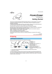
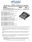
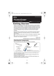
INSTALLATION INSTRUCTIONS
Product
GD8000 Docking Station
7160-0194-01, -02, -03, -04, -05, -06
Revision
Form #
Rev. C
INST-437
This instruction sheet is for the GD8000
docking station.
*These instructions are for the docking station only. For instructions on features, set-up
and operation of the GD8000 computer, please refer to the manuals provided by General
Dynamics Itronix with the computer.
** This docking station is designed to be used with a variety of Gamber-Johnson mounting
systems. Installation instructions for other Gamber-Johnson products are provided with
each individual product.
IMPORTANT SAFETY INFORMATION for
INSTALLERS
Safety is dependent on the proper installation and servicing of this docking station. It is
important to read and follow all instructions before installing this product.
To properly install a Gamber-Johnson docking station you must have a good understanding
of automotive electrical procedures and systems, along with proficiency in the installation
and service of aftermarket vehicle equipment.
There are no adjustments required at any time of the electrical components within the
docking station. Opening the docking station will void the product warranty.
Product Mounting Disclaimer
Gamber-Johnson is not liable under any theory of contract or tort law for any loss, damage, personal injury, special, incidental or consequential damages for personal injury or other damage
of any nature arising directly or indirectly as a result of the improper installation or use of its products in vehicle or any other application. In order to safely install and use Gamber-Johnson
products full consideration of vehicle occupants, vehicle systems (i.e., the location of fuel lines, brakes lines, electrical, drive train or other systems), air-bags and other safety equipment is
required. Gamber-Johnson specifically disclaims any responsibility for the improper use or installation of its products not consistent with the original vehicle manufactures specifications
and recommendations, Gamber-Johnson product instruction sheets, or workmanship standards as endorsed through the Gamber-Johnson Certified Installer Program.
If you need assistance or have questions, call Gamber-Johnson at 1-800-456-6868
Page 1 of 6
During Installation
zDO NOT connect this docking station to the vehicle battery until:
1. ALL other electrical connections are made
2. Mounting of ALL components is complete
3. VERIFICATION that no shorts exist in the entire system
zDO NOT install equipment or route wiring or cords in the deployment path of any
air bag.
zWhen drilling into the vehicle, DO make sure that both sides of the surface are
clear of anything that could be damaged.
CAUTION: If wiring is shorted to the frame, high current conductors can cause
hazardous sparks resulting in electrical fires or flying molten metal.
After Installation
zTest the docking station to ensure that it is working properly.
File these instructions in a safe place and refer to them when performing
maintenance or re-installing.
WARNING: Failure to follow all safety precautions and instructions may result
in property damage, serious injury or death.
PRE-INSTALLATION RECOMMENDATIONS
Conduct a "Bench Test"
Gamber-Johnson strongly advises a "bench test" be conducted to verify that all electronic
and software issues are resolved prior to installation:
1. Make sure computer is operational by itself.
2. Insert computer into docking station and verify that the computer is operating in the
dock.
3. Interconnect entire assembly and verify start-up of all components, including other
equipment (printers, modems, scanners, etc.).
*Gamber-Johnson also recommends positioning of all mounts and equipment in the vehicle
prior to the actual install to verify that mounting locations are safe and practical.
Page 2 of 6
POWER SUPPLY INFORMATION
This docking station has a built-in power supply and is designed to be used with an 11 - 28
volt DC system. The voltage output is factory set at 19 volts and current limited to 4.5
amps. Power is provided using the wires located on the back side of the docking station.
WIRING INSTRUCTIONS
IMPORTANT: Make sure that you have read this entire section before you begin wiring!
Refer to Figure 2
1. Install docking station into vehicle, making sure that all bolts are tight.
2. Attach the BLACK ground wire to the location where the vehicle battery grounds to
vehicle chassis.
3. Attach the RED wire to the supply voltage (V+) from the vehicle.
IMPORTANT REMINDERS:
zUse only SAE J1128 Type GPT number 14 AWG stranded wire (minimum) to attach the
docking station to the vehicle's electrical system.
zConnect lead wires to the disconnect pigtail using the butt splice connectors provided with the
docking station. Caution: The butt splice connections must be made as close
to the docking station as possible using the disconnect pigtail provided with the docking
station. The disconnect must be easily accesible. When assembling the butt splice connectors
use only Panduit crimp tools CT-100, CT-600, CT-1525, CT-1550 OR CT-1551.
zRoute the lead wires to the battery. Total wire in the circuit must not exceed 30 feet and
must conform to SAE standard J1128.
zProtect the lead wires from abrasion and chafing by using wire loom or conduit, and route
away from moving parts or areas where high temperatures may occur.
zConnection of the supply voltage (V+) must be kept as close to the battery as possible.
zThe power connection must be made with the 10 amp in-line fuse and fuse holder provided
with the dock. Connect the fuse holder to the lead wire using the butt splice connectors
provided with fuse holder. When assembling the butt splice connectors use only Panduit
crimp tools CT-100, CT-600, CT-1525 or CT-1551.
The fuse holder location must be kept within 10 inches of the connection to the
battery positive, away from moving parts, and temperatures that exceed 180 degrees F.
Caution: If the fuse holder requires replacement it should be replaced by qualified service
personnel using Littlefuse part number FHM1 (Gamber-Johnson part number 11689). This
device conforms to ASTM standard D471 and SAE standard J1128.
zFuse must be inserted in supplied fuse holder. Caution: For continued protection against risk
of fire replace only with the same type and rating of supplied fuse. The provided fuse is UL
Listed, rated at 10 amp, 32 volt AC/DC fast acting.
zIf a timing device is used follow the instructions of the manufacturer of that device. It must
be wired in-line with the supply voltage (V+) to the docking station.
zIf you have any installation questions, please call Gamber-Johnson customer support at
1-800-456-6868
Page 3 of 6
Figure 2
Ground to Vehicle Chassis
14 AWG (black wire) J1128 TYPE GPT
Panduit #BSN14-C
Butt Splice connects to
black lead from dock
-
+
10"
Panduit #BSN14-C
Butt Splice connects to
red lead from dock
Fuse
Vehicle Battery
14 AWG (red wire) J1128 TYPE GPT
Connect in-line fuse holder to lead
wire using Panduit #BSN14-C
Butt Splice connectors
Inserting the computer
into the vehicle dock
Figure 3
1. Make sure the latch handle is in the
"Unlatched" position. If you received the
dock in the latched position, you will need
to unlatch it before inserting the computer.
To unlatch the dock, press the latch button
and pull forward on the latch handle. The
latch handle should move forward about
1/4". (See Figure 3)
Latch button
Latch Handle in
"Unlatched" position
Figure 4
2. Insert the computer: (See Figure 4)
a. Align the center notch in the
computer with the front retaining
hook.
b. Lower the back of the computer
down onto the locating pins and
docking connector. Press
downward slightly to make sure
the computer is resting on the
bumpers mounted on the deck.
Page 4 of 6
Figure 5
3. Push the latch handle in until the latch
catches and holds the handle. You should
hear an audible click when the latch
engages. (See Figure 5.)
The push button latch can be locked for
added security.
Align notch
with hook
Undocking and removing a computer (Without LAN Usage)
from the vehicle dock
1. Make sure the latch button is unlocked. (Unlock with key if locked).
2. Push in and hold the latch button.
3. With the latch button pushed in, pull out on the latch handle.
4. Lift the back of the computer up and lift it out of the Vehicle Dock.
Undocking and removing an Operating computer (With LAN
Usage) from the vehicle dock (It is important to do an orderly
shutdown when using a LAN computer)
1. Click on the Undock Compter tab listed
on the start menu. (See Figure 6.)
2. Wait until the Undock Complete window
pops up on the computer screen. Once the
window pops up it is safe to remove the
computer from the dock. (See Figure 7.)
3. On 7160-0194-05 & 7160-0194-06 units
turn the power switch (on the front of the
dock) to the off position.
4. Make sure the latch button is unlocked.
(Unlock with key if locked).
5. Push in and hold the latch button.
6. With the latch button pushed in, pull out
on the latch handle.
7. Lift the back of the computer up and lift
it out of the Vehicle Dock.
Figure 6
Figure 7
Page 5 of 6
External Antenna Options
The GD8000 vehicle dock gives you the option of blocking either one or both of the external
antenna connectors from contacting the mechanical RF switches in the computer. This may
be required if the external antennas are not yet available or you do not want to switch to an
external antenna.
To block the contact(s), place one of the provided caps over the appropriate pins on the
external antenna connector and use the provided screw to install it into the dock.
Dual Cap blocks
both contacts
Single Cap positioned to
block WLAN contact
Single Cap positioned to
block WWAN contact
Cable Restraint
Attach the peripheral cables to the cable restraint
bracket with the cable ties provided in the hardare
bag.
Figure 8
CABLE TIES
Dock Indicating LED's
POWER LED is on when dock has external power and the latch is in the closed positon (with
or without computer in dock). DOCK LED is on when the condition above is met and the
computer is docked and is turned on. Note: Units 7160-0194-05 and 7160-0194-06 have a
manual switch that needs to be turned on as well.
Page 6 of 6