1
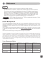
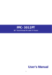
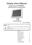
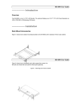
User's Manual
FP4200-OR
42-inch (107.1cm) Color LCD Display
Conformity according to the Council Directive 93/42/EEC concerning Medical
Devices.
Use this product after carefully reading this Manual and understanding the
contents.
Store this manual in a safe place for future reference.
◆Carefully read this User's Manual and use
the product properly. Before using it, also
read "Safety Precautions."
◆If you have lost the manual, contact your
dealer. We will reissue a manual.
Contents
1. Safety Precautions
2. Equipment Symbols
3. Cleaning Instructions
4. Disposal of the Unit
5. Application and Function Description
6. Features
7. Connection Method
8. Adjustment Method
9. Reference
10. Compatible Signals
11. Specifications
12. Contact Information
1
4
6
7
8
9
10
12
32
33
35
37
Revision History
The revision letter changes with related comments each time the document is updated.
Revision
Comment
A
Initial release of this document
Power Management
This Power Management System helps you to save energy by switching your monitor into a
low-power consumption mode when it has not been used for a certain period of time. Power
Management System operates with VESA DPMS compliant video card installed in your
Workstation.
Canvys highly recommends setting DPMS to activate after 15 minutes of non-usage in order
to optimize your displays lifetime and to avoid Image retention damage. We also recommend
users:
Not to leave the same image or viewing frame too long in one position.
Frequently changing and moving of image and viewing frame will help to avoid Image retention (also
called “Image Sticky”). Image retention is a phenomenon inherent to TFT LCD displays technology
itself, and as such, the occurrence of this “ghosting” effect is considered normal operation by the LCD
glass manufacturer. As a result, Canvys is not responsible for this damage and does not warrant any
displays against the occurrence of Image Sticking. We strongly advise that you follow the operating
recommendations listed above.
Power Management Modes
State
Normal
operation
Horizontal Sync
Vertical Sync
Video
Power Indicator
Active
Active
Active
LED ON
Power
Consumption
250W Max
DPMS Standby DPMS Suspend DPMS off
Inactive
Active
Blanked
Green Flashing
(1sec interval)
Less than 20W
Active
Inactive
Blanked
Green Flashing
(1sec interval)
Less than 20W
Inactive
Inactive
Blanked
Green Flashing
(1sec interval)
Less than 20W
Safety Precautions
I CAUTION
Symbol Description
Caution!-This symbol alerts you to important operating
considerations or a potential operating condition that
could damage equipment. Refer to user's manual or
operation's manual for precautionary instructions.
II CLASSIFICATION
MEDICAL EQUIPMEN T
WITH RESPECT TO ELECTRIC SHOCK,
FIRE AND MECHANICAL HAZARD S ONLY IN
ACCORDANCE WITH UL60601-1 AN D
CAN/CSA C22.2 NO.601. 1
49CG
Class I :
No applied parts
Protection against harmful ingress of water is IPX0.
Not suitable for use in the presence of flammable anesthetic's or oxygen.
Mode of operation: Continuous.
III External Equipment
External equipment intended for connection to signal input / output or other connectors, shall
comply with UL/EN 60601-1 for medical electrical equipment. In addition, all such combination
system shall comply with the standard IEC 60601-1-1, Safety requirements for medical electrical
systems. Equipment not complying with UL/EN/IEC 60601-1 shall be kept outside the patient
environment, as defined on the systems standard.
IV Intended Use
The equipment is intended to be used as a component of a medical patient monitoring system.
1
III FCC
FCC Information
FCC(U. S. Federal Communications Commission)
This equipment has been tested and found to comply with the limits for a Class B digital
device, pursuant to part 15 of the FCC Rules. These limits are designed to provide reasonable
protection against harmful interference in a residential installation. This equipment generates,
uses, and can radiate radio frequency energy, and if not installed and used in accordance with
the instructions, may cause harmful interference to radio communications. However, there is
no guarantee that interference will not occur in a particular installation. If this equipment does
cause unacceptable interference to radio or television reception, which can be determined by
turning the equipment off and on, the user is encouraged to try to correct the interference by one
or more of the following measures:
● Reorient or relocate the receiving antenna.
● Increase the separation between the equipment and receiver.
● Connect the equipment into an outlet on a circuit different from that to which the receiver is connected.
● Consult your dealer or an experienced radio/TV technician for help.
FCC Warning:
To assure continued FCC compliance, the user must use a grounded power supply cord and
the provided shielded video interface cable with bonded ferrite cores. Also, any unauthorized
changes or modifications to this monitor would void the user's authority to operate this device.
IV Precautions
● Make sure to carefully read the Operating Manual prior to using the monitor in order to
properly use the monitor.
● Note that, excluding those cases where a responsibility for legal compensation is
recognized, the manufacturer shall bear absolutely no responsibility for damage to this
product by a customer or a third party that results from the ignoring of contents entered in
this Operating Manual and mistaken use.
● Follow the instructions below for safety use of the LCD Monitor.
- To avoid electric shock, do not attempt to remove any cover or touch the inside of the
monitor. Only a qualified service technician should open the monitor case.
- Do not insert metal objects or spill liquid into the LCD monitor through cabinet slots. They may cause accident fire, electric shock or failure. If a foreign object inserted or water
penetrated, unplug the AC cable and have the monitor serviced.
- Do not cover or block the vent holes in the case.
- Disconnect the power plug from the AC outlet if you will not use it for an indefinite period of time.
- Do not touch the screen directly with your fingers. You may damage the screen, and oil
from your skin is difficult to move.
- Do not apply pressure to the screen. The LCD is very delicate.
2
● If your LCD monitor does not operate normally, if there are any unusual
sounds or smells coming from it Disconnect AC power cord from monitor immediately
and contact Canvys for service.
V Environment
-
3
Place the monitor on a flat and leveled surface.
Place the monitor in a well-ventilated place.
Keep sunlight away from monitor.
Keep monitor away from: Overly hot, cold, humid and dusty places.
Keep monitor away from strong magnetic fields.
Equipment Symbols
Electrical and Electronic Equipment Symbols
In addition to the equipment symbols described in your user's manual, the following symbols
may be appear on the monitor.
Alternating current.
Direct current.
European Union Declaration of Conformity.
FCC. USA only. Complies with applicable US government (Federal Communications
Commission) radio-frequency interference regulations.
Fragile. Handle with care.
Indicates front.
Keep dry. Protect from rain.
Mercury. This product consists of devices that may contain mercury, which must be
recycled or disposed of in accordance with local, state, or country laws.
ON. Power connection to the mains.
Recycled materials or may be recycled.
Stacking limit by number.
Standby or power indicator.
This way up.
USB connector port.
4
This symbol indicates that the waste of electrical and electronic equipment must not
be disposed as unsorted municipal waste and must be collected separately. Please
contact an authorized representative of the manufacturer for information concerning
the decommissioning of your equipment
ATTENTION: Consult accompanying documents.
DANGER - Shock Hazard. Dangerous voltage. To reduce the risk of electric shock,
do not remove cover. Refer servicing to qualified service personnel.
5
Cleaning Instructions
Cleaning Instructions
Using a spray applicator, apply any of the approved liquids from the list below and use a
soft lint free cloth to clean the screen.
1. Water
2. Windex Blue (glass surfaces only)
3. Mild Soap
Notice:
This monitor has been adjusted specifically for use in the region to which it was originally
shipped. If the product is used outside the region, it may not operate in the specifications.
Please wait 20-40 minutes after powering on the monitor before adjusting, as it takes roughly
this same amount of time for the optimum performance of the electrical parts.
The screen may have defective pixels. These pixels may appear as slightly light or dark area on
the screen. This is due to the characteristics of the panel itself, and not the monitor.
The backlight of the LCD panel has a fixed life span. When the screen becomes dark or begins
to flicker, please contact your dealer.
Do not press on the panel or edge of the frame strongly, as this may result in the display
malfunction, such as the interference patterns, etc. If pressure is continually applied to the LCD
panel, it may deteriorate or damage your LCD panel.
Do not scratch or press on the panel with any sharp objects, such as a pencil or pen as this may
result in damage on the panel. Do not attempt to brush with tissues as this may scratch the LCD
panel.
When you bring the monitor from cold temperature room into a high temperature room or
when your room temperature goes up quickly from low to high, dew condensation may occur
inside and outside the monitor. In this case, do not turn on the monitor. Please wait till dew
condensation disappears. Otherwise it may cause some damages to the monitor.
Prolonged operation of an LCD with the same content on the same screen area may
result in a form of image retention. You can avoid or significantly reduce the occurrence
of this phenomenon by using a screen saver. You can activate a screen saver in the
“Display Properties” window of your workstation. Canvys recommends setting screen
saver activation after 5 minutes of non-usage. In case you are working with the same
image or an application with static image elements for several hours continuously (so
that the screensaver is not activated); change the image content regularly to avoid image
retention of the static elements.
Image retention is a phenomenon inherent to TFT LCD displays technology itself, and as
such, the occurrence of this “ghosting” effect is considered normal operation by the LCD glass
manufacturer. As a result, Canvys is not responsible for this damage and does not warrant
any displays against the occurrence of Image Sticking. We strongly advise that you follow the
operating recommendations listed above.
6
Disposal of the Unit
●Do not dispose of this product with general wastes.
●Follow your local regulations or rules upon dispose of this product.
●Hg WARNING
This product consists of devices that may contain mercury, which must be recycled or
disposed of in accordance with local, state, or country laws.
(Within this product, the backlight lamps in the display contain mercury.)
7
Application and Function Description
●Some Basic Facts
The liquid-crystal display (LCD) monitor supports the most common resolutions from 640
x 480 (VGA) up to 1920 x 1080 and presents sharp, low-radiation images.
With the OSD touch key on the bottom right side of the display leaves ample space on
your desk for other peripheral equipment.
●Function Descripion
The medical flat-screen display is built into a slim and ergonomic housing. The monitor
displays 16.7 million colors with a resolution of 1920 x 1080 pixels.
The signal is equivalent to the analog and digital standard signals of your PC.
After connection of the signal the flat-screen display automatically adapts, as far as
possible, to the VGA signal and presents a stable and centered image. Additional display
parameters, such as brightness and contrast, can be adjusted via the on-screen menu.
The equipment supplied includes the signal cables, the power supply with power cord
and this user manual.
8
Features
●42-inch LCD display with 2 million pixels
This color LCD display has a multi-scanning function corresponding to the resolution
from VGA 640 x 400 to WUXGA 1920 x 1080. This is also compliant with VESA standard
display mode.
●High-intensity, high-contrast
Beautiful and clear images of the brightness of 700 cd/m2 and contrast ratio of 3500:1
have been achieved. Viewing angles are the wide range of 178 degrees in both
horizontal and vertical directions (CR>=10). The unit has installed our unique automatic
brightness stabilizing circuit that restrains deteriorations and brightness drifts when power
is turned on. Gamma curve adjustments are made by OSD. This is for various modality
terminals, medical image displays for PACS*1, and graphics.
●Remote control port
This color LCD display has the remote control port that controls the functions of the
monitor.
●Power management
This unit has loaded the power management system. The power management mode
functions when either horizontal or vertical signals or both disappears, and it reduces
power consumption to less than 20W.
●VESA® standard wall / arm mountings
The unit is compliant with VESA's hanging tools. The tilt stand is detachable; the unit can
be set for wall-hanging or arm according to users' environment.
Note 1) PACS: Picture Archive & Communication System
9
Connection Method
1. Confirm that your computer is off. Then, confirm that the main switch of the color LCD monitor
on the back is off.
Caution
AC Main Power supply Switch
The AC main power supply switch interrupts the AC input to the display. Placing the switch
in the ON (I) position allows display to power-up, if the AC input is connected.
Placing the switch in the OFF (O) position shall cause the display to power down.
2. Connect the signal cable (for PC input)
Connect the VGA connector of the monitor and the analog RGB output connector with the
attached VGA cable.
Connect the DVI connector of the monitor and the digital RGB output connector with the
attached DVI cable (24-pin DVI).
10
3. Connect Video signal Cable (for video device output)
Connect S-Video connector of the LCD monitor and an S-Video output device with the
attached S-Video cable. For composite signal connect the BNC connector of the monitor and a
composite video output device with the composite video cable.
4. Connect component Video connector of the LCD monitor and a component Video output
device with the component video cable. Connect HDMI connector of the LCD monitor and a
HDMI output device with the HDMI cable.
11
Adjustment Method
Names and Functions of Each Part
① Touch key
Power ON/OFF
・Pressing “Power” key turns on the LCD display.
・Pressing “Power” key for more than three seconds turns the power off.
OSD control
・When “Menu” key is pressed while images are on screen, OSD* will appear on screen.
*OSD stands for on-screen-display. Its function is to display information such as characters
and symbols.
・Execution of selected items and display of submenus can be
performed while OSD is on screen.
Press “Enter” key: execute/ select items/ save data
Source select
・Pressing “Source” key (VGA,DVI,HDMI...) changes the present source.
② POWER indicator (Power/ Power management display)
・The indicator illuminates green when power normally on.
・The indicator illuminates orange when power management function on or no signals.
・The indicator goes out when power off.
③ IR Receiver: Receives IR signals from the remote control.
④ Main power supply switch: Main switch of the LCD display.
12
⑤ AC inlet: Connect the attach AC cord to the inlet (See accessory box for cable).
⑥ CVBS Video input/output connector: Composite signal input. (See accessory box for
cable).
⑦ Component/RGBS input/output connector: When using component input to watch a DVD,
HD (High Definition) or RGBS video image. The component video connector cable is connected
to this and a component output video device. (See accessory box for cable).
⑧ S-Video input/output connector: S-Video signal input. (See accessory box for cable).
⑨ Analog input connector VGA: Analog video signal input. The analog signal cable is plugged
into this.
⑩ Digital input connector DVI: Digital video signal input. (See accessory box for cable).
⑪ Digital input connector HDMI: Digital video signal input. The provided digital signal cable is
plugged into this. (See accessory box for cable).
⑫ Control input connector GPIO DIN-9
⑬ Calibration connector USB: Connect with PC to calibrate Gamma curve.
13
Mounting
The Monitor can be mounted onto the wall or stand.
If you intend to mount the monitor on the wall, we strongly recommend that you use wall mount
kits with attached M8*12mm screws and can load more than monitor weight, that you ensure it
is securely and safely installed.
CAUTION:
When mounting the monitor, take care to tighten the retention screws or bolts until fully secure,
but do not over tighten. Over tightening the retention screws or bolts may cause them to become
stripped, rendering them useless.
Wall Mounting Installation
The Monitor has Video Electronics Standards Association (VESA) standard mounting holes
tapped into the rear panel. The standard holes are M8 set at 400 mm x 200 mm or 200mm x
200mm apart.
To mount the Monitor onto the wall or stand, please follow the steps below.
Step 1: Select the location on the wall for the wall-mounting bracket.(Listed VESA)
Step 2: Carefully mark the locations of the four screw holes in the bracket on the wall
Step 3: Drill four pilot holes at the marked locations on the wall for the bracket retention screws.
Step 4: Align the wall-mounting bracket screw holes with the pilot holes.
Step 5: Secure the mounting-bracket to the wall by inserting the retention screws into the four
pilot holes and tightening them.
Step 6: Insert the four monitor mounting screws provided in the wall mounting kit into the four
screw holes on the real panel of the LCD Monitor and tighten until the screw shank is secured
against the rear panel.
Step 7: Align the mounting screws on the monitor rear panel with the mounting holes on the
bracket.
Step 8: Carefully insert the screws through the holes and gently pull the monitor downwards
until the monitor rests securely in the slotted holes. Ensure that all four of the mounting screws
fit snuggly into their respective slotted holes.
Step 9: Secure the LCD Monitor by fastening the retention screw of the wall-mounting bracket.
Step 10: Secure the LCD Monitor by fastening the retention screw of the wall-mounting bracket. 14
Charts of OSD Adjustment Functions
The charts displays the function tree and brief explanations of the functions.Color,LCD,and other
adjustments have submenus under each tree.
● OSD display
Main menu display
• Exit• • • • • • • • • • • • • • • • • • • • • • • • • • • • • • • • • • • • • • • • • • • • • • • • • • • • • Close the OSD screen
• Input Source Settings
Exit• • • • • • • • • • • • • • • • • • • • • • • • • • • • • • • • • • • • • • • • • • Return to Main Menu
Analog VGA• • • • • • • • • • • • • • • • • • • • • • • • • • • • • Select Analog video input for Main channel
Digital• • • • • • • • • • • • • • • • • • • • • • • • • • • • • • • • • • • • • • • Select DVI digital video input for Main channel
HDMI• • • • • • • • • • • • • • • • • • • • • • • • • • • • • • • • • • • • • • • Select HDMI digital video input for Main channel
S-Video• • • • • • • • • • • • • • • • • • • • • • • • • • • • • • • • • • • • Select S-video video input for Main channel
CVBS• • • • • • • • • • • • • • • • • • • • • • • • • • • • • • • • • • • • • • • Select Composite video input for Main channel
YPbPr/YCbCr• • • • • • • • • • • • • • • • • • • • • • • • • • Select Component video input for Main channel
RGBS• • • • • • • • • • • • • • • • • • • • • • • • • • • • • • • • • • • • • • Select R, G, B, Xs-sync video input for Main channel
• Image Settings
Exit• • • • • • • • • • • • • • • • • • • • • • • • • • • • • • • • • • • • • • • • • • • Return to Main Menu
Auto Setup• • • • • • • • • • • • • • • • • • • • • • • • • • • • • • • Automatic screen size/position adjustment
Brightness• • • • • • • • • • • • • • • • • • • • • • • • • • • • • • Adjust the backlight of the full screen by the range from 0 to 100
Black Level• • • • • • • • • • • • • • • • • • • • • • • • • • • • • Adjust the black level offset for the Main channel by the range from 0 to 100
Contrast• • • • • • • • • • • • • • • • • • • • • • • • • • • • • • • • • • • Adjust the contrast for the Main channel by the range from 0 to 100
Saturation• • • • • • • • • • • • • • • • • • • • • • • • • • • • • • • • Adjust the saturation for the Main channel by the range from 0 to 100
Hue• • • • • • • • • • • • • • • • • • • • • • • • • • • • • • • • • • • • • • • • • • Adjust the hue for the Main channel by the range from 0 to 100
Sharpness• • • • • • • • • • • • • • • • • • • • • • • • • • • • • • • Adjust the sharpness for the Main channel by the range from 0 to 24
Display
Exit• • • • • • • • • • • • • • • • • • • • • • • • • • • • • Return to Exit of Image Setting page
H.Position• • • • • • • • • • • • • • • • • • • Adjust horizontal screen position for Main channel
V.Position• • • • • • • • • • • • • • • • • • • Adjust vertical screen position for Main channel
Clock• • • • • • • • • • • • • • • • • • • • • • • • • • Adjust the clock for the video signals for Main channel
Phase• • • • • • • • • • • • • • • • • • • • • • • • • Adjust the phase for the video signals for Main channel
Video Setup• • • • • • • • • • • • • • • • • • • • • • • • • • • • • * Notice: Only support for S-video & CVBS & YPbPr/PCbCr & RGBS
Exit• • • • • • • • • • • • • • • • • • • • • • • • • • • • • • • • • • • • • • Return to Exit of Image Setting page
Main MADI Mode• • • • • • • • • • • • • • • Motion adaptive De-interlacing that support Off & Normal & Adaptive three
modes
Noise Reduction
Exit• • • • • • • • • • • • • • • • • • • • • • • • • • • • • Return to Exit of Video Setup of Image Setting page
Dynamic NR mode• • • • • Dynamic NR mode that support Off & High & Medium & Low & Adaptive five
Modes
•
•
•
•
•
•
•
•
•
MPEG NR mode
MPEG NR mode that support On & Off two modes
Sharpness Noise coring Off, adaptive Low, Medium, High
Film Mode• • • • • • • • • • • • • • • • • • • • • • • • • • • Film Mode that support 3:2 & 3:2-2:2 & Off & 2:2 four modes
DCDi• • • • • • • • • • • • • • • • • • • • • • • • • • • • • • • • • • • DCDi support Off & On two modes
15
• Color Mode Settings
Exit• • • • • • • • • • • • • • • • • • • • • • • • • • • • • • • • • • • • • • • • • • Return to Main Menu
Color Temp.
Exit• • • • • • • • • • • • • • • • • • • • • • • • • • • • • Return to Exit of Color Mode Settings page
Cool• • • • • • • • • • • • • • • • • • • • • • • • • • • • Bluish white used for general use
Neutral• • • • • • • • • • • • • • • • • • • • • • • • White close to natural light mainly used for publishing trade
Warm• • • • • • • • • • • • • • • • • • • • • • • • • • Reddish white suitable mainly for photo modifications
User
Exit• • • • • • • • • • • • • • • • Return to Exit of Color Temp. of Color Mode Settings page
Red Gain• • • • • • • User adjusts the gain of Red by the range from 0 to 100
Green Gain• • • User adjusts the gain of Green by the range from 0 to 100
Blue Gain• • • • • • User adjusts the gain of Blue by the range from 0 to 100
Gamma
Exit• • • • • • • • • • • • • • • • • • • • • • • • • • • • • Return to Exit of Color Mode Settings page
Gamma 1.8• • • • • • • • • • • • • • • • Set Gamma curve to curve 1.8
Gamma 2.0• • • • • • • • • • • • • • • • Set Gamma curve to curve 2.0
Gamma 2.2• • • • • • • • • • • • • • • • Set Gamma curve to curve 2.2
Gamma 2.4• • • • • • • • • • • • • • • • Set Gamma curve to curve 2.4
Monochorme• • • • • • • • • • • • • • Set full screen without color
Calibration• • • • • • • • • • • • • • • • • • Calibrate monitor setting by using external device
DICOM• • • • • • • • • • • • • • • • • • • • • • • Set Gamma curve to DICOM curve
• Multi-PIP Settings
Exit• • • • • • • • • • • • • • • • • • • • • • • • • • • • • • • • • • • • • • • • • •
PIP mode• • • • • • • • • • • • • • • • • • • • • • • • • • • • • • • •
PIP Source
Exit• • • • • • • • • • • • • • • • • • • • • • • • • • • • • Analog VGA• • • • • • • • • • • • • • •
Digital• • • • • • • • • • • • • • • • • • • • • • • • •
HDMI• • • • • • • • • • • • • • • • • • • • • • • • • •
S-Video• • • • • • • • • • • • • • • • • • • • • •
CVBS• • • • • • • • • • • • • • • • • • • • • • • • •
YPbPr/YCbCr• • • • • • • • • • • • •
RGBS• • • • • • • • • • • • • • • • • • • • • • • • •
PIP Display
Exit• • • • • • • • • • • • • • • • • • • • • • • • • • • • •
PIP Size
Exit• • • • • • • • • • • • • • • • • • • • •
PIP Size• • • • • • • • • • • • • •
PIP H-Size• • • • • • • • • •
PIP V-Size• • • • • • • • • •
PIP Position
Exit• • • • • • • • • • • • • • • • • • • • •
PIP H. Position• • •
PIP V. Position• • • •
Swap• • • • • • • • • • • • • • • • • • • • • • • • • • • • • • • • • • • • • • •
Return to Main Menu
Select PIP mode to Off or PIP or POP
Return to Exit of Multi-PIP Settings page
Select Analog video input for Sub channel
Select DVI digital video input for Sub channel
Select HDMI digital video input for Sub channel
Select S-video video input for Sub channel
Select Composite video input for Sub channel
Select Component video input for Sub channel
Select R, G, B, Xs-sync video input for Sub channel
Return to Exit of Multi-PIP Settings page
Return to Exit of PIP Display of Multi-PIP Settings page
Adjust the full size for Sub channel display
Adjust the H size for Sub channel display
Adjust the V size for Sub channel display
Return to Exit of PIP Display of Multi-PIP Settings page
Adjust the H position for Sub channel display by the range from 0 to 100
Adjust the V position for Sub channel display by the range from 0 to 100
Swap source between Main and Sub channel
16
PIP Picture
Exit• • • • • • • • • • • • • • • • • • • • • • • • • • • • •
Black Level• • • • • • • • • • • • • • • • •
Contrast• • • • • • • • • • • • • • • • • • • • • •
Saturation• • • • • • • • • • • • • • • • • • •
Hue• • • • • • • • • • • • • • • • • • • • • • • • • • • • •
Sharpness• • • • • • • • • • • • • • • • • •
• OSD Misc.
Exit• • • • • • • • • • • • • • • • • • • • • • • • • • • • • • • • • • • • • • • • • • •
OSD Position
Exit• • • • • • • • • • • • • • • • • • • • • • • • • • • • •
OSD H.Position• • • • • • • • • •
OSD V.Position• • • • • • • • • • •
Language
Exit• • • • • • • • • • • • • • • • • • • • • • • • • • • • •
English• • • • • • • • • • • • • • • • • • • • • • • •
Francais• • • • • • • • • • • • • • • • • • • • • •
Deutsch• • • • • • • • • • • • • • • • • • • • • •
Italiano• • • • • • • • • • • • • • • • • • • • • • • •
Espanol• • • • • • • • • • • • • • • • • • • • • •
日本語• • • • • • • • • • • • • • • • • • • • • • • • •
簡體中文• • • • • • • • • • • • • • • • • • • • •
OSD Timer• • • • • • • • • • • • • • • • • • • • • • • • • • • • • • •
Transparent• • • • • • • • • • • • • • • • • • • • • • • • • • • • •
• Management Settings
Exit• • • • • • • • • • • • • • • • • • • • • • • • • • • • • • • • • • • • • • • • • • •
Scaling
Exit• • • • • • • • • • • • • • • • • • • • • • • • • • • • •
Scaling• • • • • • • • • • • • • • • • • • • • • • • •
Zoom• • • • • • • • • • • • • • • • • • • • • • • • • •
Her. Zoom• • • • • • • • • • • • • • • • • • •
Ver. Zoom• • • • • • • • • • • • • • • • • • •
Auto Setup ON/OFF• • • • • • • • • • • • • • • •
ALS ON/OFF• • • • • • • • • • • • • • • • • • • • • • • • • • •
Auto Source SW• • • • • • • • • • • • • • • • • • • • • •
KeypadDrive
Exit• • • • • • • • • • • • • • • • • • • • • • • • • • • • •
Brightness• • • • • • • • • • • • • • • • • •
Sensitivy• • • • • • • • • • • • • • • • • • • • •
•
•
•
Recall • • • • • • • • • • • • • • • • • • • • • • • • • • • • • • • • • • • •
17
Return to Exit of Multi-PIP Settings page
Adjust the black level offset for the Sub channel by the range from 0 to 100
Adjust the contrast for the Sub channel by the range from 0 to 100
Adjust the saturation for the Sub channel by the range from 0 to 100
Adjust the hue for the Sub channel by the range from 0 to 100
Adjust the sharpness for the Sub channel by the range from 0 to 24
Return to Main Menu
Return to Exit of OSD Misc.
Adjust the H position for OSD by the range from 0 to 100
Adjust the V position for OSD by the range from 0 to 100
Return to Exit of OSD Misc
Display OSD in English
Display OSD in French
Display OSD in German
Display OSD in Italian
Display OSD in Spanish
Display OSD in Japanese
Display OSD in Simplified Chinese
Adjust OSD display time
Adjust OSD display transparent
Return to Main Menu
Return to Exit of Management Settings page
Support Full & 1:1 & 4:3 & 16:9 & 16:10 Screen 5 modes
Adjust the full size for Main channel display(Must under Full scaling mode)
Adjust the H size for Main channel display (Must under Full scaling mode)
Adjust the V size for Main channel display (Must under Full scaling mode)
On/off ‘’Auto Adjustment’’ Function
On/off ‘’Auto Luminance System ’’ Function
Automatically select the signal source
Return to Exit of Management Settings page
Control the touch key backlight 4~22
Control the touch key sensitivy 0~100
Initialize to the factory settings and delete the specify User setting you
saved
Photos Describe the OSD Adjustment Functions
The below photos will detail introduce every menu of OSD tree and brief explanations of the
functions.
Detail of Adjustment Items
Exit
Close the Main Menu.
In addition, this page will show below messages:
(1)Information for input timing of Main channel .
(2)Indicate which source display for Main channel.
(3)Indicate which source display for Sub channel.
(4)Record how long time display for this monitor already.
Input Source Setting
You can select source for Main channel from Analog VGA, Digital, HDMI, S-video, CVBS,
YPbPr/ PCbCr, RGBS.
18
Image Settings
Adjust values of below items for Main channel. Beside VideoSetup that only support on S-video
& CVBS & YPbPr/PCbCr & RGBS.
* Notice: VideoSetup will be disable under Analog VGA or Digital source.
Exit
Return to Main Menu.
Auto Setup
When you press ‘’Auto Setup’’ will show ‘’Auto Adjusting’’ on the screen that do automatically
adjust the size, position, brightness, contrast and the like of the screen. When first using this
color display or input new timing will perform this adjustment. When ‘’Auto Adjusting’’ disappear
from the screen means it have finished the ‘’Auto Setup’’ function.
Black Level
Adjust the black level offset for the Main channel by the range from 0 to 100.
Black Level
50
Contrast
Adjust the contrast for the Main channel by the range from 0 to 100.
19
Saturation
Adjust the saturation for the Main channel by the range from 0 to 100.
Hue
Adjust the hue for the Main channel by the range from 0 to 100.
Sharpness
Adjust the sharpness for the Main channel by the range from 0 to 24.
Sharpness
12
Display
Adjust the Horizontal & Vertical position & clock & phase for Main channel.
• Exit
Return to Exit of Image Setting page.
• H.Position
Adjust horizontal screen position for Main channel by the range from 0 to 100.
• V.Position
Adjust vertical screen position for Main channel by the range from 0 to 100.
20
• Clock
Adjust the frequency sampling rate of horizontal pixels for Main channel, to equal the video
source’s value,Thus minimizing artifacts of shimmering vertical lines.
* Notice: Only support on Analog VGA source.
• Phase
Adjust ADC sampling clock phase for Main channel, so that the screen image appear crisp and
focused.
* Notice: Only support on Analog VGA source.
Color Mode Settings
Selecting this control allows you select color temperature or gamma curve.
Exit
Return to Main Menu.
Color Temp.
Selecting this control allows you to select preset color temperature of Cool, Neutral, Warm, or
User for customized red, green and blue levels.
21
• Exit
Return to Exit of Color Mode Settings page.
• Cool
Bluish white used for general use.
• Neurtal
White close to natural light mainly used for publishing trade.
• Warm
Reddish white suitable mainly for photo modifications.
• User
Selecting this control allows you to adjust the Red gain, Green gain and Blue gain individually to
match personal preference.
Exit
Return to Exit of Color Mode Settings page.
Red Gain
You can adjusts the gain of Red by the range from 0 to 100.
Green Gain
You can adjusts the gain of Green by the range from 0 to 100.
Blue Gain
You can adjusts the gain of Blue by the range from 0 to 100.
22
Gamma
Selecting this control allows you to choose which gamma curve that you want.
• Exit
Return to Exit of Color Mode Settings page.
• Gamma 1.8
Set Gamma curve to curve 1.8
• Gamma 2.0
Set Gamma curve to curve 2.0
• Gamma 2.2
Set Gamma curve to curve 2.2
• Gamma 2.4
Set Gamma curve to curve 2.4
• Monochrome
Set full screen without color.
• Calibration
Set Gamma curve to calibration mode.
• DICOM
Set Gamma curve for medical standards.
23
Multi-PIP Settings
Selecting this control allows you to adjust below items settings for Sub channel.
* Notice: PIP Display & Swap & PIP Picture only active when PIP Mode set to PIP or POP.
Exit
Return to Main Menu.
PIP mode
Select PIP mode to Off mode or PIP mode or POP mode as below:
PIP source
You can select source for Sub channel from Analog VGA, Digital, HDMI, S-video, CVBS, YPbPr/
PCbCr, RGBS (Gray area are not available to choose).
Please find the below matrix to see the combinations for Main channel with Sub channel if you
set to PIP mode or POP mode.
Main
channel
VGA
DVI
HDMI
S-video
CVBS
YPbPr
RGBS
VGA
X
O
O
O
O
O
O
DVI
O
X
X
O
O
O
O
Sub channel
HDMI S-video CVBS
O
O
O
X
O
O
X
O
O
O
X
O
O
O
X
O
O
O
O
O
O
YPbPr
O
O
O
O
O
X
X
RGBS
O
O
O
O
O
X
X
24
PIP Display
Selecting this control allows you to adjust the size and position for Sub channel.
• Exit
Return to Exit of Multi-PIP Settings page.
• PIP Size
Selecting this control allows you to adjust the size for Sub channel.
Exit
Return to Exit of PIP Display of Multi-PIP Settings page.
PIP Size
Adjust the full size for Sub channel display.
PIP H Size
Adjust the H size for Sub channel display.
PIP V Size
Adjust the V size for Sub channel display.
25
• PIP Position
Selecting this control allows you to adjust the position for Sub channel.
Exit
Return to Exit of PIP Display of Multi-PIP Settings page.
PIP H.Position
Adjust the H position for Sub channel display by the range from 0 to 100.
PIP V.Position
Adjust the V position for Sub channel display by the range from 0 to 100.
Swap
Swap source between Main and Sub channel.
PIP Picture
Selecting this control allows you to adjust the below items settings for Sub channel.
• Exit
Return to Exit of Multi-PIP Settings page.
• Black Level
Adjust the black level offset for the Sub channel by the range from 0 to 100.
• Contrast
Adjust the contrast for the Sub channel by the range from 0 to 100.
26
• Saturation
Adjust the saturation for the Sub channel by the range from 0 to 100.
• Hue
Adjust the hue for the Sub channel by the range from 0 to 100.
• Sharpness
Adjust the sharpness for the Sub channel by the range from 0 to 24.
*
Notice: Only Sub channel support are S-video or CVBS or YPbPr/ PCbCr & or RGBS.
OSD Misc.
Selecting this control allows you to adjust below items settings for OSD.
Exit
Return to Main Menu.
OSD Position
Selecting this control allows you to adjust position for OSD.
27
• Exit
Return to Exit of OSD Misc.
• OSD H.Position
Adjust the H position for OSD by the range from 0 to 100.
• OSD V.Position
Adjust the V position for OSD by the range from 0 to 100.
Language
Selecting this control allows you to choose below languages that you want to display for OSD.
• Exit
Return to Exit of OSD Misc.
• English
Display OSD in English.
• Francais
Display OSD in French.
• Deutsch
Display OSD in German.
• Italiano
Display OSD in Italian.
• Espanol
Display OSD in Spanish.
• 日本語
Display OSD in Japanese.
• 簡體中文
Display OSD in Simplified Chinese.
28
OSD Timer
Adjust OSD display time that support 0 & 5 & 10 & 15 & 20 & 25 & 30
OSD will not disappear if set to 0
OSD will disappear after 5 sec if set to 5 (just like that for 10 & 15 & 20 & 25 & 30)
Transparent
Adjust OSD display transparent from 0 to 7 by one step.
29
Management Settings
Selecting this control allows you to adjust below items settings for Main channel.
Exit
Return to Main Menu.
Scaling
Selecting this control allows you to adjust below items relate to image scaling for Main channel.
• Exit
Return to Exit of Management Settings page.
• Scaling
Support Full & 1:1 & 4:3 & 16:9 & 16:10 5 modes.
• Zoom
Adjust the full size for Main channel display.
* Notice: To Support Zoom Mode, must be under full scaling mode for each source.
• Her. Zoom
Adjust the H size for Main channel display.
* Notice: To Support Horiz. Zoom, must be under Full scaling mode for each source.
30
• Ver. Zoom
Adjust the V size for Main channel display.
* Notice: To Support Ver. Zoom, must be under Full scaling mode for each source.
• Auto Setup ON/OFF
Select this function to on or off ‘’Auto Setup’’ Function.
• Auto Source SW
Select this function to on or off ‘’Auto Source’’ Function.
KeypadDrive
Control touch key pad.
• Exit
Return to Exit of Management Settings page.
• Brightness
Control the touch key backlight 4~22.
• Sensitivy
Control the touch key sensitivy 0~100.
Recall
Select this function to recall all OSD adjustments to the factory default settings and delete the
specify User setting you used.
31
Reference
DDC*1
◆ This unit has loaded a function compliant with DDC-2B, VESA* standard.
The DDC function is located in 15-pin D-sub connector and 24-pin DVI-D connector.
This function reads into the set data written in the color LCD display internal device in
advance on start-up of Windows®95/98/Me/2K/XP or Windows®7 and sets the detailed
information of the color LCD display in the system file in order to achieve Plug & Play.
Data reading from the color LCD display is done through a video signal cable, which
needs to be connected when Windows®95/98/Me/2K/XP or Windows®7 is on.
Note
*1DDC (Display Data channel) and*2 VESA are registered trademarks of Video
Electronics Standards Association.
Power Management
This Power Management System helps you to save energy by switching your monitor into a
low-power consumption mode when it has not been used for a certain period of time. Power
Management System operates with VESA DPMS compliant video card installed in your
Workstation.
Canvys highly recommends setting DPMS to activate after 15 minutes of non-usage in order
to optimize your displays lifetime and to avoid Image retention damage. We also recommend
users:
Not to leave the same image or viewing frame too long in one position.
Frequently changing and moving of image and viewing frame will help to avoid Image retention (also
called “Image Sticky”). Image retention is a phenomenon inherent to TFT LCD displays technology
itself, and as such, the occurrence of this “ghosting” effect is considered normal operation by the LCD
glass manufacturer. As a result, Canvys is not responsible for this damage and does not warrant any
displays against the occurrence of Image Sticking. We strongly advise that you follow the operating
recommendations listed above.
Power Management Modes
State
Normal
operation
Horizontal Sync
Vertical Sync
Video
Power Indicator
Active
Active
Active
LED ON
Power
Consumption
250W Max
DPMS Standby DPMS Suspend DPMS off
Inactive
Active
Blanked
Green Flashing
(1sec interval)
Less than 20W
Active
Inactive
Blanked
Green Flashing
(1sec interval)
Less than 20W
Inactive
Inactive
Blanked
Green Flashing
(1sec interval)
Less than 20W
32
Compatible Signals
Applicable Signals Timings
※The display may not work correctly with timings other than listed below.
Resolution
640 x 350
640 x 400
640 x 480
720 x 350
800 x 600
1024 x 768
1152 x 864
1280 x 960
1360 x 768
1280 x 1024
1680 x 1050
1600 x 1200
1920 x 1080
1280 x 720
33
VGA & DVI
H-Freq(KHz) V-Freq(Hz)
31.47
70
37.86
85.08
31.47
70.07
37.86
85.08
31.47
50.02
31.47
59.93
37.86
72.81
37.5
75
43.27
85.01
35
66.67
31.47
70.08
37.96
85.04
35.16
57.16
37.88
60.02
48.83
66.89
48.08
72.19
46.88
75
53.67
85.06
35.52
43.48
47.74
59.94
56.48
70
57.7
72
60.02
75.03
68.68
85
67.5
75
60
60
75
75
47.71
60.015
63.98
60.02
79.98
75.02
64.674
59.883
75
59.94
55.6
50
66.7
59.99
36.994
49.925
44.38
60,00
Timing mode name
VGA 350-70
VGA 350-85
VGA 400-70
VGA 400-85
VGA 480-50
VGA 480-60
VESA 480-72
VESA 480-75
VESA 480-85
MAC 480-66
VGA-TEXT 350-70
XGA II 350-85
SVGA-56
VESA 600-60
MAC 600-66
SVGA -72
VESA 600-75
VESA 600-85
IBM-8514A i
VESA768-60
XGA-70
XGA-72
VESA 768-75
VESA 768-85
MAC 864-75
VESA 960-60
VESA 960-75
VESA 1360x768-60
VESA 1024-60
VESA 1024-75
VESA 1680x1050-60
UXGA 1200-60
1080P50
1080P60
720P50
720P60
S-Video
Resolution
NTSC
PAL
Composite
Resolution
NTSC
PAL
YPbPr
Resolution
1080i
720P
NTSC
PAL
1080P50
1080P60
RGBS
Resolution
RGBS_VGA60
RGBS_SVGA60
RGBS_XGA60
RGBS_SXGA60
RGBS_NTSC
RGBS_PAL
HDMI
Resolution
1080P
1080i
720P
NTSC
34
Specifications
Product name :42"Color LCD Display
Specifications
Items
LCD display device
107.1cm (42 inch)Color TFT Normally Black
Pixel pitch
Horizontal 0.4845mm x Vertical 0.4845mm
Display area
Horizontal 930.24mm x Vertical 523.26mm
Pixel
1920 x 1080 pixels
Display gradation
16.77 billion (8 bit each) x3
Response Time
8 ms (Typ.) (Gray to Gray)
Contrast Ratio
3500 : 1 (Typ.)
Brightness
700 cd/m2 (Typ.) ; 550 cd/m2 (Min.)
Standard viewing
angle
Horizontal : 178 deg.
Input signal
(1) VGA (15-pin D-SUB)
Video signal: Analog RGB(0.714Vp-p/75Ω)
Horizontal sync and composite sync signal: TTL level 2.5~5.5V
(2) HDMI (19-pin HDMI) connector
(3) DVI (24-pin DVI) connector compliant with DVI 1.0
(4) S-Video connector
Color signal: 1Vp-p/75 Ω
Brightness signal: 1Vp-p/75 Ω (composite sync signal)
(5) BNC connector: Composite signal: 1Vp-p/75 Ω
(6) BNC connector: Compnent signal: Y(0.714Vp-p/75 Ω), Pb/Cb, Pr/Cr (0.35Vp-p/75 Ω)
RGBS signal: R.G.B (0.714Vp-p/75 Ω)
S: Sync (2-5Vp-p)
Temperature
35
Vertical : 178 deg.
Operating
Temperature
: 10~40°C
Humidity(non-condensation) : 30~75%
Air pressure
: 700~1060hPa
Storage and Transport
-20~60°C
10~90%
500~1060hPa
Power Supply
100-240V~, 50/60Hz, 4-2A
Power Consumption
Approx.250W Max.
External dimensions
Width 1020.2mm x Height 613.2mm x Depth 120mm
Mass
Approx. 30 kg
International standards
UL60601-1, CSA C22.2 NO.601.1,
FCC, ICES, CE(IEC/EN60601-1, EN60601-1-2), CISPR
Less than 20W when power management on.
External Dimensions
36
Contact Information
Contact Information:
Canvys - Visual Technology Solutions
A Division of Richardson Electronics
Raiffeisenstr. 5
78166 Donaueschingen
Germany
Tel: +49-771-83000
Fax: +49-771-830080
[email protected]
www.canvys.de
Copyright Notice
This document is copyrighted. All rights are reserved. Neither this document, nor any part
of it, may be reproduced or copied in any form or by any means-graphical, electronic, or
mechanical including photocopying, taping or information storage and retrieval systems
without written permission of Canvys a division of Richardson Electronics
© 2010 Canvys a division of Richardson Electronics. All rights reserved.
Model : FP4200-OR
37
MDLL9PR010