1
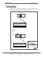
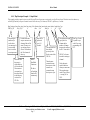
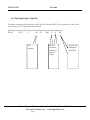
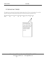
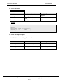
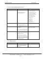
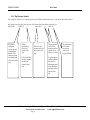
A Sierra Monitor Company
Driver Manual
(Supplement to the FieldServer Instruction Manual)
FS-8704-13 GE-SRTP Ethernet Driver
APPLICABILITY & EFFECTIVITY
Effective for all systems manufactured after January 1, 1999
Instruction Manual Part Number FS-8704-13
Version 1.00
Revision 1.a
9/26/2002
FS-8704-13 GE-SRTP
Driver Manual
TABLE OF CONTENTS
1.
2.
GE-SRTP Driver Description ............................................................................................................................................... 1
Driver Scope of Supply.......................................................................................................................................................... 2
2.1
Supplied by FieldServer Technologies for this driver............................................................................................. 2
2.2
Provided by user............................................................................................................................................................. 2
3. Hardware Connections........................................................................................................................................................... 3
4. Configuring the FieldServer as a GE-SRTP Driver Client.............................................................................................. 4
4.1
Data Arrays ..................................................................................................................................................................... 4
4.2
Client Side Connections................................................................................................................................................ 5
4.3
Client Side Nodes........................................................................................................................................................... 5
4.4
Client Side Map Descriptors ........................................................................................................................................ 5
4.4.1
FieldServer Specific Map Descriptor Parameters............................................................................................ 5
4.4.2
Driver Specific Map Descriptor Parameters..................................................................................................... 6
4.4.3
Timing Parameters ................................................................................................................................................ 6
4.4.4
Map Descriptor Example 1 – Simple Read. ..................................................................................................... 7
4.4.5
Map Descriptor Example 2 – Simple Write ..................................................................................................... 8
4.4.6
Map Descriptor Example 3 – Handling Bits.................................................................................................... 9
5. Configuring the FieldServer as a GE-SRTP Driver Server........................................................................................... 10
5.1
Data Arrays ................................................................................................................................................................... 10
5.2
Server Side Connections............................................................................................................................................. 11
5.3
Server Side Nodes........................................................................................................................................................ 12
5.4
Server Side Map Descriptors...................................................................................................................................... 12
5.4.1
FieldServer Specific Map Descriptor Parameters.......................................................................................... 12
5.4.2
Driver Specific Map Descriptor Parameters................................................................................................... 13
5.4.3
Timing Parameters .............................................................................................................................................. 13
5.4.4
Map Descriptor Example. .................................................................................................................................. 14
6. Driver Notes........................................................................................................................................................................... 15
6.1
Driver Stats.................................................................................................................................................................... 15
6.2
Driver Error messages ................................................................................................................................................. 16
6.3
Scaling............................................................................................................................................................................ 17
FieldServer Technologies 1991 Tarob Court Milpitas, California 95035 (408) 262-2299 fax: (408) 262-9042
Visit our website: www.fieldserver.com
E-mail: [email protected]
Page I
FS-8704-13 GE-SRTP
Driver Manual
1. GE-SRTP Driver Description
The GE-SRTP driver allows the FieldServer to transfer data to and from devices over Ethernet
using GE-SRTP Driver protocol. There are two Ethernet ports standard on the FieldServer. The
FieldServer can emulate either a Server or Client.
The GE-SRTP driver is capable of read & writing the data tables of a GE series 90 PLC which is
equipped with an Ethernet port.
The driver is capable of exposing its communication statistics so that they can be monitored by a
downstream device.
FieldServer Technologies 1991 Tarob Court Milpitas, California 95035 (408) 262-2299 fax: (408) 262-9042
Visit our website: www.fieldserver.com
E-mail: [email protected]
Page 1
FS-8704-13 GE-SRTP
Driver Manual
2. Driver Scope of Supply
2.1 Supplied by FieldServer Technologies for this driver
UTP cable (7 foot) for Ethernet connection
UTP cable (7 foot) for RS232 use
RJ45 to DB9F connector adapter
RJ45 to DB25M connection adapter
RS485 connection adapter
Driver Manual.
2.2 Provided by user
GE-SRTP System.
FieldServer Technologies 1991 Tarob Court Milpitas, California 95035 (408) 262-2299 fax: (408) 262-9042
Visit our website: www.fieldserver.com
E-mail: [email protected]
Page 2
FS-8704-13 GE-SRTP
Driver Manual
3. Hardware Connections
Make sure the device IP_address is configured to be on the same IP network as on the
FieldServer. Use a crossover cable if the FieldServer is connected directly to the PLC
device. Use a straight cable if the FieldServer is connected to a hub.
ETHERNET CPU
A
CPU
364
P5
P6
P7
P8
R1
RS232
P1
Rx T x
P2
Rx
Tx
P3
Rx T x
P4
P5
Rx T x Rx T x
R2
N1
RS485
P6
Rx Tx
P7
Rx T x
P8
Rx
Tx
R1
Rx
Tx
R2
Net 1
Rx T x
Tx
Net 2
Rx Con
N2
10 Base T
ETHERNET
Tx Rx C o n
Pwr
P4
Act
P3
Sys
P2
Co m
P1
2
Run
1
Options:
1 RJ45
2 Transceiver AAUI to 10base-T
NON-ETHERNET CPU
B
CCM
321
CPU
2 UNDERNEATH
P6
P7
P8
R1
RS232
P1
Rx
Tx
P2
Rx T x
P3
P4
Rx T x Rx T x
P5
P6
Rx T x Rx T x
R2
N1
RS485
P7
Rx Tx
P8
R1
Rx T x
Rx Tx
R2
Rx
Tx
Net 1
T x Rx C o n Tx
Net2
Rx Con
(408)-262-2299
N2
10 Base T
ETHERNET
Pwr
P5
Ru n
P4
Ac t
P3
Com
P2
Sys
P1
GE-SRTP
CONNECTION DIAGRAM
BASE NAME:
FILE NAME: FS-T28704-13 .VSD
DATE: 12/7/01
BY:
MN
FieldServer Technologies 1991 Tarob Court Milpitas, California 95035 (408) 262-2299 fax: (408) 262-9042
Visit our website: www.fieldserver.com
E-mail: [email protected]
Page 3
FS-8704-13 GE-SRTP
Driver Manual
4. Configuring the FieldServer as a GE-SRTP Driver Client
For a detailed discussion on FieldServer configuration, please refer to the instruction manual for the
FieldServer. The information that follows describes how to expand upon the factory defaults
provided in the configuration files included with the FieldServer (See “.csv” files on the driver
diskette).
This section documents and describes the parameters necessary for configuring the FieldServer to
communicate with a GE-SRTP Driver Server.
The configuration file tells the FieldServer about its interfaces, and the routing of data required. In
order to enable the FieldServer for GE-SRTP Driver communications, the driver independent
FieldServer buffers need to be declared in the “Data Arrays” section, the destination device
addresses need to be declared in the “Client Side Nodes” section, and the data required from the
servers needs to be mapped in the “Client Side Map Descriptors” section. Details on how to do this
can be found below.
Note that in the tables, * in dicates an optional parameter, with the bold legal value being the
default.
4.1 Data Arrays
Section Title
Data_Arrays
Column Title
Data_Array_Name
Function
Provide name for Data Array
Data_Format
Provide data format. Each data array can only
take on one format.
Data_Array_Length
Number of Data Objects. Must be larger than
the data storage area required for the data
being placed in this array.
Legal Values
Up to 15 alphanumeric
characters
FLOAT, BIT, UInt16, SInt16,
Packed_Bit, Byte,
Packed_Byte, Swapped_Byte
1-10,000
Example
//
Data Arrays
Data_Arrays
Data_Array_Name,
DA_AI_01,
DA_AO_01,
DA_DI_01,
DA_DO_01,
Data_Format,
UInt16,
UInt16,
Byte,
Byte,
Data_Array_Length
200
200
200
200
FieldServer Technologies 1991 Tarob Court Milpitas, California 95035 (408) 262-2299 fax: (408) 262-9042
Visit our website: www.fieldserver.com
E-mail: [email protected]
Page 4
FS-8704-13 GE-SRTP
Driver Manual
4.2 Client Side Connections
Section Title
Adapter
Column Title
Function
Legal Values
Adapter
Specify which port the device is
connected to the FieldServer
N1
Protocol
Example
Specify protocol used
GE_SRTP, SRTP
//
Client Side Connections
Connections
Adapter, Protocol
N1,
SRTP
4.3 Client Side Nodes
Section Title
Nodes
Column Title
Function
Node_Name
Provide name for node
Node_ID
Node ID of physical server node
(PLC)
IP address of physical server node
(PLC)
Specify protocol used
Specify on which port the device is
connected to the FieldServer
IP_Address
Protocol
Adapter
Legal Values
Up to 32 alphanumeric
characters
1-255
Must be on the same subnet as
the server or gateway
GE_SRTP, SRTP
N1
Example
//
Client Side Nodes
Nodes
Node_Name, Protocol, IP_Address,
Adapter
Node_A,
SRTP,
192.168.1.174, N1
4.4 Client Side Map Descriptors
4.4.1 FieldServer Specific Map Descriptor Parameters
Column Title
Map_Descriptor_Name
Data_Array_Name
Data_Array_Location
Function
Name of this Map Descriptor
Name of Data Array where data is
to be stored in the FieldServer
Starting location in Data Array
Function
Function of Client Map Descriptor
Legal Values
Up to 32 alphanumeric characters
One of the Data Array names from
“Data Array” section above
0 to maximum specified in “Data
Array” section above
RDBC, WRBC, WRBX
FieldServer Technologies 1991 Tarob Court Milpitas, California 95035 (408) 262-2299 fax: (408) 262-9042
Visit our website: www.fieldserver.com
E-mail: [email protected]
Page 5
FS-8704-13 GE-SRTP
Driver Manual
4.4.2 Driver Specific Map Descriptor Parameters
Column
Title
Node_Name
Function
Name of Node to fetch data from
Data_Type
Data type
Use one of the Data Types specified in brackets.
Legal Values
One of the node names specified in
“Client Node Descriptor” above
Discrete Inputs (%I)
Discrete Outputs (%Q)
Discrete Temporaries (%T)
Discrete Internals (%M)
Genius Global Data (%G)
Analog Inputs (%AI)
Analog Outputs (%AQ)
Registers (%R)
%SA Dis crete
%SB Discrete
%SC Discrete
%S Discrete (%S)
Length
Length of Map Descriptor
Address
Ensure that the length does not exceed the table length
in the PLC.
Starting address of read block / write block
1 - 1000
1,2,3
Positive whole numbers
The 1st element of each Data type Table is referred to
as address one.
Format
Use to override the default format for obtaining data.
Bit tables are by default read by reading whole bytes
at a time (If the Length is 10 then 10 bytes of data are
read and placed in 10 data array locations)
Bit, Byte
The format for %AI,%AQ and %R
cannot be changed.
If you wish to read bits instead then use this parameter
. (If the Length is 10 then 10 bits are read and each bit
is stored in its own location.)
4.4.3 Timing Parameters
Column Title
Scan_Interval
Function
Rate at which data is polled
Legal Values
>0.1s
FieldServer Technologies 1991 Tarob Court Milpitas, California 95035 (408) 262-2299 fax: (408) 262-9042
Visit our website: www.fieldserver.com
E-mail: [email protected]
Page 6
FS-8704-13 GE-SRTP
Driver Manual
4.4.4 Map Descriptor Example 1 – Simple Read.
This example provides a map descriptor to read 10 bytes of Discrete Input states, starting at the very first Discrete Input. The data is stored in a data array
called DA_DI and the first input is stored at location 100 in the array (101st element). The PLC is polled every 2 seconds
Map_Descriptor_Name, Data_Array_Name, Data_Array_Offset, Function, Scan_Interval, node_name, Address, Length, Data_Type
CMD_AI_01
, DA_AI_01
Map descriptor
names may be
used in driver
error messages. It
is not essential,
but it is useful to
use unique names.
,0
, rdbc
Location in the data
array at which the first
element of data will be
stored. The arrays are
zero referenced so an
offset of 100 indicates
the 101st element of
the array.
The name of the
data array in
which the driver
will store the data.
The name must
correspond to a
data array defined
in the data array
section of the
CSV file.
, 1.0s
, Node_A
,1
, 10
Read will be
performed
every 2.0
Seconds.
RDBC =
Read Block
Continuous.
The driver
will read data
from the PLC
continuously.
The node must have
been defined
previously in the
Nodes section of the
CSV file.
The node name
connects this map
descriptor to a node
which in turn
connects the map
descriptor to a port.
, %AI
The address and length
specify the first
element and the
number of elements
that must be read from
the PLC’s data tables.
GE PLC’s reference
data tables starting at
element 1.
Unless otherwise
specified the driver
reads bytes and words.
This map descriptor
reads 10 bytes of data
– covering %I1 to
%I79.
FieldServer Technologies 1991 Tarob Court Milpitas, California 95035 (408) 262-2299 fax: (408) 262-9042
Visit our website: www.fieldserver.com
E-mail: [email protected]
Page 7
Data Type. Use the
% symbol as you
would if you were
programming a GE
PLC.
FS-8704-13 GE-SRTP
Driver Manual
4.4.5 Map Descriptor Example 2 – Simple Write
This example writes data from the Fieldserver data array called DA_AO to the PLC identified as NODE1. The write is repeated every 5 seconds. Ten word
values are written to the PLC’s %AQ Data Table starting at location 20.
Map_Descriptor_Name, Data_Array_Name, Data_Array_Offset, Function, Scan_Interval, node_name, Address, Length, Data_Type
Write_AO
, DA_AO
,0
, wrbc
Write
continuously
, 5.0s
, Node1
, 20
, 10
Write to PLC
Table element
number 20 to 29
inclusive (10
elements)
, %AQ
Write to the %AQ
(Analog Output)
table in the PLC.
FieldServer Technologies 1991 Tarob Court Milpitas, California 95035 (408) 262-2299 fax: (408) 262-9042
Visit our website: www.fieldserver.com
E-mail: [email protected]
Page 8
FS-8704-13 GE-SRTP
Driver Manual
4.4.6 Map Descriptor Example 3 – Handling Bits.
This example shows how to read 1 couple of bits from a data table rather than reading a whole byte. The bits can cross byte boundaries. Here we read 2 bits
from table %T starting at bit 8. This is most useful when writing to the PLC in cases where you want to turn one particular bit on or off.
Map_Descriptor_Name, Data_Array_Name, Data_Array_Offset, Function, Scan_Interval, node_name, Address, Length, Data_Type, Format
Read_DI
, DA_T
, 100
, rdbc
, 2.0s
, PLC-1
,8
,2
, %T
, Bit
The format parameter tells the
driver to override the default data
type and to specifically read bits. In
this case the bit states are stored in
the data array in two separate
elements at DA_T[100] and
DA_T[101]
FieldServer Technologies 1991 Tarob Court Milpitas, California 95035 (408) 262-2299 fax: (408) 262-9042
Visit our website: www.fieldserver.com
E-mail: [email protected]
Page 9
FS-8704-13 GE-SRTP
Driver Manual
5. Configuring the FieldServer as a GE-SRTP Driver Server
For a detailed discussion on FieldServer configuration, please refer to the instruction manual for the
FieldServer. The information that follows describes how to expand upon the factory defaults
provided in the configuration files included with the FieldServer (See “.csv” files on the driver
diskette).
This section documents and describes the parameters necessary for configuring the FieldServer to
communicate with a GE-SRTP Driver Client
The configuration file tells the FieldServer about its interfaces, and the routing of data required. In
order to enable the FieldServer for GE-SRTP Driver communications, the driver independent
FieldServer buffers need to be declared in the “Data Arrays” section, the FieldServer virtual node(s)
needs to be declared in the “Server Side Nodes” section, and the data to be provided to the clients
needs to be mapped in the “Server Side Map Descriptors” section. Details on how to do this can be
found below.
Note that in the tables, * indicates an optional parameter, with the bold legal value being the
default.
5.1 Data Arrays
Section Title
Data_Arrays
Column Title
Data_Array_Name
Function
Provide name for Data Array
Data_Format
Provide data format. Each data array can only
take on one format.
Data_Array_Length
Number of Data Objects. Must be larger than
the data storage area required for the data
being placed in this array.
Legal Values
Up to 15 alphanumeric
characters
FLOAT, BIT, UInt16, SInt16,
Packed_Bit, Byte,
Packed_Byte, Swapped_Byte
1-10,000
Example
//
Data Arrays
Data_Arrays
Data_Array_Name,
DA_AI_01,
DA_AO_01,
DA_DI_01,
DA_DO_01,
Data_Format,
UInt16,
UInt16,
Byte,
Byte,
Data_Array_Length
200
200
200
200
FieldServer Technologies 1991 Tarob Court Milpitas, California 95035 (408) 262-2299 fax: (408) 262-9042
Visit our website: www.fieldserver.com
E-mail: [email protected]
Page 10
FS-8704-13 GE-SRTP
Driver Manual
5.2 Server Side Connections
Section Title
Adapter
Column Title
Function
Legal Values
Adapter
Specify which port the device is
connected to the FieldServer
N1
Protocol
Specify protocol used
GE_SRTP, SRTP
Example
//
Server Side Connections
Connections
Adapter, Protocol
N1,
SRTP
FieldServer Technologies 1991 Tarob Court Milpitas, California 95035 (408) 262-2299 fax: (408) 262-9042
Visit our website: www.fieldserver.com
E-mail: [email protected]
Page 11
FS-8704-13 GE-SRTP
Driver Manual
5.3 Server Side Nodes
Section Title
Nodes
Column Title
Function
Node_Name
Provide name for node
Node_ID
Node ID of physical server
node
Specify protocol used
Protocol
Legal Values
Up to 32 alphanumeric
characters
1-255
SRTP
Example
//
Server Side Nodes
Nodes
Node_Name, Node_ID, Protocol,
GE_Srv_11, 11,
SRTP
,
5.4 Server Side Map Descriptors
5.4.1 FieldServer Specific Map Descriptor Parameters
Column Title
Map_Descriptor_Name
Data_Array_Name
Data_Array_Location
Function
Name of this Map Descriptor
Name of Data Array where data is
to be stored in the FieldServer
Starting location in Data Array
Function
Function of Server Map Descriptor
Legal Values
Up to 32 alphanumeric characters
One of the Data Array names from
“Data Array” section above
0 to maximum specified in “Data
Array” section above
Passive
FieldServer Technologies 1991 Tarob Court Milpitas, California 95035 (408) 262-2299 fax: (408) 262-9042
Visit our website: www.fieldserver.com
E-mail: [email protected]
Page 12
FS-8704-13 GE-SRTP
Driver Manual
5.4.2 Driver Specific Map Descriptor Parameters
Column Title
Data_Type
Function
Data type
Use one of the Data Types
specified in brackets.
Legal Values
Discrete Inputs (%I)
Discrete Outputs (%Q)
Discrete Temporaries (%T)
Discrete Internals (%M)
Genius Global Data (%G)
Analog Inputs (%AI)
Analog Outputs (%AQ)
Registers (%R)
%SA Discrete
%SB Discrete
%SC Discrete
%S Discrete (%S)
Length
Address
Length of Map Descriptor
1 - 1000
Ensure that the length does not
exceed the table length in the PLC.
Starting address of read block /
write block
1,2,3
Positive whole numbers
The 1st element of each Data type
Table is referred to as address one.
Format
Has no meaning on the server as
the driver responds based on the
nature of the request
N/A
The map descriptors should be
considered to be the definitions of
data tables in a PLC. Thus one map
descriptor can be used to respond
to bit or byte requests.
5.4.3 Timing Parameters
Column Title
Scada_Hold_Timeout
Function
Specifies time server side waits
before responding to client that
node is offline on FieldServer
client side.
Legal Values
>1.0s
FieldServer Technologies 1991 Tarob Court Milpitas, California 95035 (408) 262-2299 fax: (408) 262-9042
Visit our website: www.fieldserver.com
E-mail: [email protected]
Page 13
FS-8704-13 GE-SRTP
Driver Manual
5.4.4 Map Descriptor Example.
In this example the FieldServer can respond to polls the request %R data provided that the request is in the range of address indicated below.
Map_Descriptor_Name, Data_Array_Name, Data_Array_Offset, Function, Node_Name, Address, Length, Data_Type
Server-R-Data
If the client is
reading then
response data will
be obtained from
this table. If the
client array writing
then incoming data
will be stored in this
array.
, TABLE_R
,0
Address 1
corresponds to
offset zero (1st
location) in the
array.
If client reads %R15
then driver responds
with data from
element 14 of the
array.
, passive, PLC1
This is a server. It
responds to polls but
does no active work
itself.
,1
, 1000 ,%R
This map descriptor
can be used to
respond to poll that
read and write to
addresses 1 to 1000.
This map descriptor
will be used to
process client
read/writes of
Register (%R) data.
If a poll attempts to
read data at address
1001 then if no
other map descriptor
covers that address
space then a no data
response will be
sent.
FieldServer Technologies 1991 Tarob Court Milpitas, California 95035 (408) 262-2299 fax: (408) 262-9042
Visit our website: www.fieldserver.com
E-mail: [email protected]
Page 14
FS-8704-13 GE-SRTP
Driver Manual
6. Driver Notes
6.1 Driver Stats
The statistics recorded by the GE-SNPX Serial Driver are slightly different from the way that
Fieldserver driver normally record statistics. This difference arises from the fact that this driver is
not a simple poll response driver. Bare in mind that a single poll can generate a large number of
response fragments.
Fragment Ack/nack messages are NOT counted as message but the bytes sent/rcvd are counted.
Connection messages are counted as messages and the bytes sent/rcvd are counted.
This driver can expose these and additional statistics by writing data to a data array.
A special map descriptor is required. The driver recognizes the map descriptor by its name which
must be "SRTP-stats" .
The following example shows how this special map descriptor can be configured.
Nodes
Node_name, Protocol
null_node, SRTP
Data_Arrays
Data_Array_Name, Data_Format, Data_Array_Length
SRTP_STATS
, UINT32
, 600
Map_blocks
Map_block_Name, Data_Array_Name, Node_name, Length
srtp-stats
, SRTP _STATS , null_node , 600
When the driver sees this map descriptor it uses the data array SRTP _STATS (in this example)
to store driver specific statistics. Only one of these map descriptors may be specified (per tier) per
FieldServer.
The driver stores the following stats for each port.. The offset into the data array can be found by
multiplying the port number by 50
Stat #
Stat Code
1 GE_STAT_BAD_SEND
2 GE_STAT_POLL_MSGS_SENT
3 GE_STAT_POLL_BYTES_SENT
4 GE_STAT_SESS_CONNECT
5 GE_STAT_DEV_CONNECT
6 GE_STAT_BAD_PDU
7 GE_STAT_BAD_PROTOCOL
8 GE_STAT_TIMEOUT
9 GE_STAT_MBOX_NAK_MAJOR
FieldServer Technologies 1991 Tarob Court Milpitas, California 95035 (408) 262-2299 fax: (408) 262-9042
Visit our website: www.fieldserver.com
E-mail: [email protected]
Page 15
FS-8704-13 GE-SRTP
Driver Manual
10 GE_STAT_MBOX_NAK_MINOR
11 GE_STAT_MBOX_NAK_CNT
12 GE_STAT_MBOX_PROG_NUM
13 GE_STAT_MBOX_SWEEP
14 GE_STAT_MBOX_PLC_STAT
15 GE_STAT_MBOX_PRIV_LVL
16 GE_STAT_DEV_CONNECT_RESP
17 GE_STAT_SESS_CONNECT_RESP
18 GE_STAT_SESS_RESPONSE
19 GE_STAT_DEV_RESPONSE
20 GE_STA T_SLAVE_BAD_PDU
21 GE_STAT_SLAVE_SENDS_BAD_MBOX
22 GE_STAT_SLAVE_SENDS_OTHER_NAK
23 GE_STAT_SLAVE_BAD_SERVICE_RQST
24 GE_STAT_ERROR_PDU_RESP_COUNT
25 GE_STAT_ERROR_PDU_RESP_CODE
26 GE_STAT_RESPONSE_MSGS_RECD
27 GE_STAT_RESPONSE_BYTES_RECD
28 GE_STAT_POLL_MSGS_RECD
29 GE_STAT_POLL_BYTES_RECD
30 GE_STAT_RESPONSE_MSGS_SENT
31 GE_STAT_RESPONSE_BYTES_SENT
6.2 Driver Error messages
The following messages are produced by the driver and written to the error log which can be viewed using
the RUInet utility program or logged using the RUIdebug utility program.
Messages marked with a *, are only printed once and then suppressed to prevent the error log being filled
with repetitive messages.
SRTP:#1 FYI. The MapDesc called <%s> is too short.
You have define a map descriptor to expose driver statistics but the length parameter must be at
least 500 long. Ensure the Data array is this long too. Edit the CSV, correct he problem and reset
the Fieldserver.
SRTP:#2 FYI. You could have used a mapDesc called <%s> to expose diagnostic info.
You may safely ignore this message. Read section 6.3 for information on how to expose the
drivers communication statistics using a data array.
SRTP:#3 Error. MapDesc=<%s> has bad data type.
You must edit the CSV file, correct the problem and then reset the FieldServer to correct this
problem. Read the manual to get a list of valid data types.
SRTP:#4 Err. Address < 1 for MapDesc=<%s>.
GE references its data elements starting at one. You have a map descriptor with an address less
than 1. The driver will assume you meant an address of one until you edit the CSV file and reset
the FieldServer.
*SRTP:#5 FYI. Capability is non-zero
This message requires no user action. It is intended for Fieldserver support engineers.
FieldServer Technologies 1991 Tarob Court Milpitas, California 95035 (408) 262-2299 fax: (408) 262-9042
Visit our website: www.fieldserver.com
E-mail: [email protected]
Page 16
FS-8704-13 GE-SRTP
Driver Manual
*SRTP:#6 FYI. Connect remaining bytes non-zero
This message requires no user action. It is intended for Fieldserver support engineers.
*SRTP:#7 Err. Destination request not supported.
*SRTP:#8 Err. Destination response not supported.
The driver has received a message that it cannot respond to. The message received is not normally
associated with reading / writing table memory and can be ignored by this driver. There is no
corrective action that you can take. If you wish, take a log file using RUIdebug and contact
Fieldserver support.
SRTP:#9 Err. Driver des not support unconfirmed messages.
The driver has been polled using a method which does not require confirmation. The driver does
not support this method. A panic is produced by this message. There is no corrective action that
you can take. If you wish, take a log file using RUIdebug and contact Fieldserver support.
SRTP:#10 Err. Session Mbox bad type. Act/Exp=%x/c0
SRTP:#11 Err. Session Mbox bad SR code. Act/Exp=%x/4f
SRTP:#12 Err. Session SR bad param. Act/Exp=%x/01
If this error occurs repeatedly or frequently then take a log using RUIdebug and contact support. If
infrequent then it indicate an occasional corrupt message. There is no corrective action you can
take to eliminate this error.
SRTP:#13 Err. Cant Process ServiceRQst=%x(h)
The driver cannot process this service request. It can only read/write table memory. There is no
corrective action you can take when this message is printed. If you wish, take a log file using
RUIdebug and contact Fieldserver support. The message is followed by a buffer dump. Recording
the buffer may be useful to Fieldserver support engineers.
SRTP:#14 Err. Cant Process Mbox=%x(h)
The driver cannot process this type of Mailbox message or a valild mailbox message was received
in an invalid context. If this message occurs frequently, take a log file using RUIdebug and contact
Fieldserver support. The message is followed by a buffer dump. Recording the buffer may be
useful to Fieldserver support engineers.
SRTP:#15 Err. Cant Process PDU=%x(h)
The driver can only process ‘connect’ and ‘data request’ PDU’s. . There is no corrective action
you can take when this message is printed. If you wish, take a log file using RUIdebug and contact
Fieldserver support. The message is followed by a buffer dump. Recording the buffer may be
useful to Fieldserver support engineers.
6.3 Scaling
The driver only supports scaling fro the following data types
Analog Inputs (%AI)
Analog Outputs (%AQ)
Registers (%R)
The scaling is only applied when the driver acts as a client.
When using scaling on an active map descriptor which writes data to a PLC ensure that the scaling
produces a number in the range 0-65536 ( an unsigned short integer).
FieldServer Technologies 1991 Tarob Court Milpitas, California 95035 (408) 262-2299 fax: (408) 262-9042
Visit our website: www.fieldserver.com
E-mail: [email protected]
Page 17