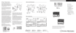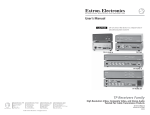
1
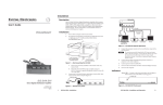
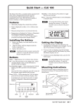
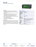
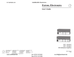
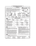
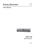
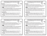
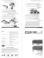
○
○
P/2 DA2xi and P/2 DA2xi MT • Installation
○
P/2 DA2xi and P/2 DA2xi MT • Installation
3
○
○
○
2
○
○
Figure 3 — Desk and projector mounting
○
○
○
For optional rack mounting, mount the P/2 DA2xi or P/2 DA2xi
MT on a VersaTools 19" 1U Rack Shelf (part #60-190-20) or a
standard Universal 1U Rack Shelf (part #60-190-01) as shown in
figure 2.
○
○
○
Digital Projector
Ceiling
○
○
Rack mounting
MO
○
The P/2 DA2xi and P/2 DA2xi MT can be mounted on a rack
shelf, under a desk or tabletop, or on a projector bracket.
NIT
OR
UT
○
○
INP
Mounting
Bolt
○
2
ON
1
○
EXT POWER (see manual)
5V
0.1A MAX
Projector
Mounting
Bracket
○
○
○
○
Figure 1 — P/2 DA2xi MT with chain
SPARE
PEAK
GAIN/
OUTPUT
P/2 DA2xi
○
Installation
○
Attach the mounting brackets to the P/2 DA2xi or
P/2 DA2xi MT with the provided machine screws (figure 3).
○
○
1.
○
○
○
○
Furniture mount or projector mount the unit using the mounting
kit (part #70-077-01, furniture [optional with the P/2 DA2xi,
standard with P/2 DA2xi MT] or #70-077-04, projector [optional
with both units]) as follows:
○
○
AUDIO
MONITOR
Furniture or projector mounting
○
○
○
INPUT
•
○
○
○
○
○
Remove the rubber feet (if installed) and mount the unit on the
rack shelf, using two screws in opposite (diagonal) corners.
○
○
○
1.
○
○
○
Figure 2 — Mounting the P/2 DA2xi or P/2 DA2xi MT on
a rack shelf
○
AM
PLI
FIE
R
ION
DIS
TRI
BUT
Use 2 mounting holes on
opposite corners.
○
•
Install blank panel(s) or other unit(s) to the rack shelf.
2.
○
•
•
3.
○
•
Insert the shelf into the rack, and secure the shelf to the rack
using the supplied machine screws.
○
Powered by computer — This unit can be powered by most
newer computers.
Power/Signal LED — Green LED = power + signal. Amber
LED = power but no signal. Off = no power.
Gain/Peak DIP switch — To compensate for longer cable runs.
Out Imp DIP switch — Changes the output impedance to be
compatible with all projectors.
Cable retention chain — To prevent a lost or misplaced input
VGA cable, the cable can be secured to the unit (either model)
with the supplied chain (attached to the right standoff nut of
the input VGA connector).
1/4 Rack Width False Front
Face Plate
DIST
A
RIBU SE
TION RIE
AMP S
LIFI
ER
MD
○
○
Features
○
AM
Both models can be powered by newer computers compatible
with the new VESA standard using pin 9 of the VGA connector as
the +5VDC source. An external power supply is also provided
for use with older computers, where power is unavailable
through the VGA connector or the available power is inadequate.
PLI
FIE
R
ION
TRI
BUT
○
DIS
AM
PLI
FIE
AM
PLI
FIE
R
R
DIS
TRI
BUT
ION
ION
TRI
BUT
○
DIS
AM
PLI
FIE
R
○
DIS
TRI
BUT
ION
AM
PLI
FIE
R
○
○
○
○
DIS
TRI
BUT
ION
○
○
The P/2 DA2xi and the P/2 DA2xi MT are distribution amplifiers
that accept video input from a VGA, XGA, or UXGA compatible
PC and distribute the signal to separately buffered outputs. Each
output can be extended with Extron VGA Mini-HR cables from 6'
to 250' in length. The MT model also has audio input and output.
Universal Rack Shelf
○
○
VersaTools Rack Shelf
○
○
○
○
○
Only products in the VersaTools line can be mounted to a
VersaTools rack shelf.
○
○
○
○
○
○
○
○
○
○
○
○
○
○
○
○
○
○
○
○
○
○
○
○
○
○
○
○
○
○
○
○
○
○
○
○
○
○
○
○
○
○
○
○
○
○
○
○
○
○
○
○
○
○
○
○
○
○
○
○
○
○
○
○
○
○
○
○
○
○
○
○
○
○
○
○
○
○
○
○
○
○
○
○
○
○
○
○
○
○
○
○
○
○
○
○
○
○
○
○
○
○
○
○
○
○
○
○
○
○
○
○
○
○
○
○
○
○
○
○
○
○
○
○
○
○
○
○
○
○
○
○
○
○
User’s Guide
○
Power ................................................ +5VDC from pin 9 of the VGA input of a PC
that complies with VESA DCC version 3
Or .......................................... 100VAC to 240VAC, 50/60 Hz, 5 watt,
external, autoswitchable; to 12VDC, 1A
power supply. P/2 DA2xi and P/2 DA2xi MT
require 0.2A.
Temperature/humidity ................. Storage -40° to +158°F (-40° to +70°C) / 10%
to 90%, non-condensing
Operating +32° to +122°F (0° to +50°C) / 10%
to 90%, non-condensing
Rack mount ...................................... Yes, with optional 1U VersaTools rack shelf,
part #60-190-20 or Universal rack shelf, part
#60-190-01
Enclosure type ................................. Metal
Enclosure dimensions .................... 1" H x 4.3" W x 3" D
2.5 cm H x 10.9 cm W x 7.6 cm D
(Depth excludes connectors.)
Product weight ................................ 0.5 lbs (0.3 kg)
Shipping weight .............................. 3 lbs (1.4 kg)
Vibration ........................................... ISTA/NSTA 1A in carton (International Safe
Transit Association)
Listings .............................................. UL, CUL
Compliances .................................... CE, FCC Class A, VCCI, AS/NZS, ICES
MTBF ................................................. 30,000 hours
Warranty ........................................... 3 years parts and labor
○
○
○
General
○
○
○
○
○
Specifications are subject to change without notice.
○
○
○
○
○
○
○
○
○
○
P/2 DA2xi
P/2 DA2xi MT
© 2003 Extron Electronics. All rights reserved.
Distribution Amplifiers
○
○
Daisan DMJ Building 6F
3-9-1 Kudan Minami
Chiyoda-ku, Tokyo 102-0074 Japan
+81.3.3511.7655
Fax +81.3.3511.7656
○
Extron Electronics, Japan
135 Joo Seng Road, #04-01
PM Industrial Building
Singapore 368363
+65.6383.4400
Fax +65.6383.4664
○
Extron Electronics, Asia
Beeldschermweg 6C
3821 AH Amersfoort
The Netherlands
+31.33.453.4040
Fax +31.33.453.4050
○
Extron Electronics, Europe
1230 South Lewis Street
Anaheim, CA 92805
USA
714.491.1500
Fax 714.491.1517
○
www.extron.com
Extron Electronics, USA
○
○
○
○
Note: This unit was tested with shielded cables on the peripheral devices. Shielded
cables must be used with the unit to ensure compliance.
○
○
Note: This equipment has been tested and found to comply with the limits for a
Class A digital device, pursuant to part 15 of the FCC Rules. These limits are designed
to provide reasonable protection against harmful interference when the equipment is
operated in a commercial environment. This equipment generates, uses and can
radiate radio frequency energy and, if not installed and used in accordance with the
instruction manual, may cause harmful interference to radio communications.
Operation of this equipment in a residential area is likely to cause harmful
interference, in which case the user will be required to correct the interference at his
own expense.
○
○
○
○
FCC Class A Notice
○
○
○
○
○
○
○
○
○
Introduction
○
68-713-01 Rev. C
Printed in the USA
06 03
○
○
○
○
○
○
○
© 2003 Extron Electronics. All rights reserved.
Extron Electronics, Europe
Daisan DMJ Building 6F
3-9-1 Kudan Minami
Chiyoda-ku, Tokyo 102-0074 Japan
+81.3.3511.7655
Fax +81.3.3511.7656
68-713-01 Rev. C
Printed in the USA
06 03
Extron Electronics, Asia
○
Extron Electronics, USA
135 Joo Seng Road, #04-01
PM Industrial Building
Singapore 368363
+65.6383.4400
Fax +65.6383.4664
○
Beeldschermweg 6C
3821 AH Amersfoort
The Netherlands
+31.33.453.4040
Fax +31.33.453.4050
○
1230 South Lewis Street
Anaheim, CA 92805
USA
714.491.1500
Fax 714.491.1517
○
www.extron.com
○
Extron Electronics, Japan
Distribution Amplifiers
○
○
P/2 DA2xi
P/2 DA2xi MT
○
Note: This unit was tested with shielded cables on the peripheral devices. Shielded
cables must be used with the unit to ensure compliance.
○
○
○
Note: This equipment has been tested and found to comply with the limits for a
Class A digital device, pursuant to part 15 of the FCC Rules. These limits are designed
to provide reasonable protection against harmful interference when the equipment is
operated in a commercial environment. This equipment generates, uses and can
radiate radio frequency energy and, if not installed and used in accordance with the
instruction manual, may cause harmful interference to radio communications.
Operation of this equipment in a residential area is likely to cause harmful
interference, in which case the user will be required to correct the interference at his
own expense.
○
○
○
○
○
○
○
○
○
○
○
FCC Class A Notice
○
○
○
○
○
○
Specifications are subject to change without notice.
○
○
+5VDC from pin 9 of the VGA input of a PC
that complies with VESA DCC version 3
100VAC to 240VAC, 50/60 Hz, 5 watt,
external, autoswitchable; to 12VDC, 1A
power supply. P/2 DA2xi and P/2 DA2xi MT
require 0.2A.
Storage -40° to +158°F (-40° to +70°C) / 10%
to 90%, non-condensing
Operating +32° to +122°F (0° to +50°C) / 10%
to 90%, non-condensing
Yes, with optional 1U VersaTools rack shelf,
part #60-190-20 or Universal rack shelf, part
#60-190-01
Metal
1" H x 4.3" W x 3" D
2.5 cm H x 10.9 cm W x 7.6 cm D
(Depth excludes connectors.)
0.5 lbs (0.3 kg)
3 lbs (1.4 kg)
ISTA/NSTA 1A in carton (International Safe
Transit Association)
UL, CUL
CE, FCC Class A, VCCI, AS/NZS, ICES
30,000 hours
3 years parts and labor
○
○
○
○
○
○
○
○
○
○
○
○
○
○
○
○
○
○
○
○
○
○
○
User’s Guide
○
○
○
○
○
○
Power ................................................
○
Or ..........................................
○
Temperature/humidity .................
○
Rack mount ......................................
○
Enclosure type .................................
Enclosure dimensions ....................
○
Product weight ................................
Shipping weight ..............................
Vibration ...........................................
○
Listings ..............................................
Compliances ....................................
MTBF .................................................
Warranty ...........................................
○
○
General
○
○
○
○
○
○
○
○
○
○
○
○
○
○
○
○
○
○
○
○
○
○
○
○
○
○
○
○
○
○
○
○
○
○
○
○
○
○
○
○
○
○
○
○
○
○
○
○
○
○
○
○
○
○
○
○
○
○
○
○
○
○
○
○
○
○
○
○
○
○
○
○
○
○
○
○
○
○
○
○
○
○
○
○
○
○
○
○
○
○
○
○
○
○
○
○
○
○
○
○
○
○
○
○
○
○
○
Introduction
○
○
○
○
Only products in the VersaTools line can be mounted to a
VersaTools rack shelf.
○
○
○
○
Universal Rack Shelf
VersaTools Rack Shelf
○
○
The P/2 DA2xi and the P/2 DA2xi MT are distribution amplifiers
that accept video input from a VGA, XGA, or UXGA compatible
PC and distribute the signal to separately buffered outputs. Each
output can be extended with Extron VGA Mini-HR cables from 6'
to 250' in length. The MT model also has audio input and output.
○
○
○
○
DIS
TRI
BUT
ION
AM
PLI
FIE
R
DIS
TRI
BUT
ION
○
AM
PLI
FIE
R
○
DIS
TRI
BUT
DIS
TRI
BUT
ION
ION
AM
PLI
FIE
AM
PLI
FIE
R
R
○
DIS
○
Both models can be powered by newer computers compatible
with the new VESA standard using pin 9 of the VGA connector as
the +5VDC source. An external power supply is also provided
for use with older computers, where power is unavailable
through the VGA connector or the available power is inadequate.
TRI
BUT
ION
AM
FIE
R
○
Features
PLI
○
MD
DIST
A
RIBU SE
TION RIE
AMP S
LIFI
ER
○
○
○
Use 2 mounting holes on
opposite corners.
DIS
TRI
BUT
ION
○
AM
PLI
FIE
R
○
○
○
○
Figure 2 — Mounting the P/2 DA2xi or P/2 DA2xi MT on
a rack shelf
○
○
1.
Remove the rubber feet (if installed) and mount the unit on the
rack shelf, using two screws in opposite (diagonal) corners.
2.
Install blank panel(s) or other unit(s) to the rack shelf.
3.
Insert the shelf into the rack, and secure the shelf to the rack
using the supplied machine screws.
○
○
○
○
○
○
• Powered by computer — This unit can be powered by most
newer computers.
• Power/Signal LED — Green LED = power + signal. Amber
LED = power but no signal. Off = no power.
• Gain/Peak DIP switch — To compensate for longer cable runs.
• Out Imp DIP switch — Changes the output impedance to be
compatible with all projectors.
• Cable retention chain — To prevent a lost or misplaced input
VGA cable, the cable can be secured to the unit (either model)
with the supplied chain (attached to the right standoff nut of
the input VGA connector).
1/4 Rack Width False Front
Face Plate
○
○
○
INPUT
MONITOR
Furniture or projector mounting
○
○
AUDIO
○
○
○
○
Furniture mount or projector mount the unit using the mounting
kit (part #70-077-01, furniture [optional with the P/2 DA2xi,
standard with P/2 DA2xi MT] or #70-077-04, projector [optional
with both units]) as follows:
○
○
1.
○
Attach the mounting brackets to the P/2 DA2xi or
P/2 DA2xi MT with the provided machine screws (figure 3).
○
Projector
Mounting
Bracket
○
○
○
Figure 1 — P/2 DA2xi MT with chain
1
2
ON
SPARE
GAIN/
PEAK
OUTPUT
○
P/2 DA2xi
○
Mounting
Bolt
○
○
INP
○
The P/2 DA2xi and P/2 DA2xi MT can be mounted on a rack
shelf, under a desk or tabletop, or on a projector bracket.
EXT POWER (see manual)
5V
0.1A MAX
○
Installation
UT
MO
NIT
OR
○
○
Rack mounting
Ceiling
○
○
○
Digital Projector
○
○
○
For optional rack mounting, mount the P/2 DA2xi or P/2 DA2xi
MT on a VersaTools 19" 1U Rack Shelf (part #60-190-20) or a
standard Universal 1U Rack Shelf (part #60-190-01) as shown in
figure 2.
○
○
Figure 3 — Desk and projector mounting
○
○
○
P/2 DA2xi and P/2 DA2xi MT • Installation
○
2
P/2 DA2xi and P/2 DA2xi MT • Installation
3
○
○
○
○
○
○
○
○
For furniture mounting, hold the unit with the attached
brackets against the underside of the table or other
furniture. Mark the location of the screw holes of the
bracket on the mounting surface.
4.
For furniture mounting, drill 3/32" (2 mm) diameter pilot
holes, 1/4" (6.3 mm) deep in the mounting surface at the
marked screw locations.
Power/Signal indicator LED — When illuminated green,
this LED indicates that the distribution amplifier is
receiving both power and a computer signal. When
illuminated amber, it indicates that the distribution
amplifier is receiving power but no computer signal. If the
LED is off when the distribution amplifier is connected to a
PC with power on, it indicates that an external power
supply is required.
2
Video Input connector — Connect a computer’s VGA UXGA output to this connector.
3
Monitor connector — Connect a local monitor to this
connector.
4
Power connector — Plug the external 12V power supply,
only when needed (see Power/Signal indicator LED above),
into this 2-pole captive screw connector. The power supply
is included with the unit and is shipped with a plug
installed. If you need to cut the power cord to a different
length and reinstall the plug, refer to figure 5 and the
following notes.
○
3.
1
○
If feet were previously installed on the bottom of the unit,
remove them.
7.
For furniture mounting, slide the receiver slightly forward or
back, then tighten all four screws to secure the unit in place.
8.
For projector mounting, secure the unit to a projector
mount or other surface by inserting the mounting bolt
through the bracket’s slotted hole.
○
For furniture mounting, align the mounting screws with
the slots in the brackets and place the unit against the
surface, with the screws through the bracket slots.
○
6.
○
For furniture mounting, insert #8 wood screws into the four
pilot holes. Tighten each screw into the mounting surface
until just less than 1/4" of the screw head protrudes.
○
○
○
○
○
○
○
○
○
○
5.
○
○
○
○
○
○
○
○
○
○
○
○
2.
○
○
○
○
○
Installation
○
○
End view of power
supply output cord
A
○
+
–
○
SECTION A–A
○
3
6
INPUT
MONITOR
Power supply output cord
○
○
6
2
12VDC
Connections, Indicators, and Controls
Power
○
A
Captive screw
connector
○
○
Figure 5 — Power connector wiring
○
7
1
When connecting the power supply, voltage polarity
is extremely important. Applying power with
incorrect voltage polarity could damage the power
supply and the amplifier. Identify the power cord
negative lead by the ridges on the side of the cord.
○
○
○
CAUTION
6
○
○
5
GAIN/PEAK
OUT IMP
P/2 DA2xi
○
EXT POWER (see manual)
5V
0.1A MAX
OUTPUT
6
9
○
ON
4
Do not tin the stripped power supply leads before
installing the captive screw connector. Tinned wires are
not as secure in the captive screw connectors and could
pull out.
○
2
○
○
1
6
2
3
○
○
○
7
MONITOR
The two power cord wires must be kept separate
while the power supply is plugged in. Remove
power before continuing.
○
INPUT
○
○
7
1
○
○
AUDIO
6
8
6
To verify the polarity before connection, plug in the power
supply with no load and check the output with a voltmeter.
○
5
6
L
○
○
P/2 DA2xi MT
OUTPUT
GAIN/PEAK
OUT IMP
EXT POWER (see manual)
5V
0.2A MAX
R
ON
○
4
7
2-bank DIP switch — (These switches only affect the video
output [ 6 ], not the “monitor” output [ 3 ]). The Gain/Peak
DIP switch should be on (up) when output cable is over 100'
(30.5 m). The Out Imp DIP switch changes output
5
○
2
○
○
1
○
○
○
Figure 4 — Front and rear panels
P/2 DA2xi and P/2 DA2xi MT • Connections
○
P/2 DA2xi and P/2 DA2xi MT • Connections
5
○
○
4
○
○
○
○
○
○
○
○
○
○
○
○
○
○
○
○
○
○
○
○
○
○
○
○
○
○
○
○
○
○
○
○
○
○
○
○
○
○
○
○
○
○
○
○
○
○
○
○
○
○
○
○
○
○
○
○
○
○
○
○
○
○
○
○
○
○
○
○
○
○
○
○
○
○
○
○
○
○
○
○
○
○
○
○
○
○
○
○
○
○
○
○
○
○
○
○
○
Audio input connector (MT model only) — Plug a
3.5 mm, mini jack audio cable from the computer’s sound
card into this connector.
8
Audio output connector (MT model only) — Insert a
3.5 mm, 5-pole, captive screw audio connector into this
connector. Wire the connector as shown below.
○
○
○
7
○
Video output connector — Connect the video output
device, such as a projector, LCD panel, or monitor, to this
connector.
○
○
○
○
Unbalanced Output
○
○
Tip
See Caution
Sleeve (s)
Tip
See Caution
○
○
○
○
○
○
○
○
○
Specifications
○
9
○
Connect the sleeve to ground (Gnd). Connecting the
sleeve to a negative (-) terminal will damage the
audio output circuits.
Local monitor cable assembly — Use this cable assembly
to connect the local monitor (video) and speaker (audio) to
the unit. The chain is used to attach the cable to the unit,
to prevent the cable from being lost or misplaced.
CAUTION
○
○
Figure 6 — Audio connector wiring
○
○
Tip
Ring
Sleeve (s)
Tip
Ring
○
○
Balanced Output
○
○
○
○
○
○
○
6
○
○
impedance. If all connections and operations are correct, yet
the output device has no picture, switch to the other position.
○
○
○
○
Specifications
○
○
○
○
○
○
○
Gain ................................................... Unity (0dB), or (1.1dB) 110%, switch-selectable
(When input = 0.7V, output = 0.7V or 0.8V,
respectively.
Peaking ............................................. Selectable: 0dB or 6dB @ 100 MHz
Bandwidth ....................................... 350 MHz (-3dB)
○
○
Video
○
○
○
○
○
○
○
○
○
○
○
○
1 VGA-UXGA RGBHV, RGBS, RGsB, RsGsBs
(1) 15-pin HD female
0.7V p-p for RGB
Analog, 0.3V to 1.5V p-p
75 ohms
15 kHz to 135 kHz
30 Hz to 170 Hz
<-38dB @ 5 MHz
1.0V
No
Sync
Input type .....................................
Output type ..................................
Min/Max Input level ..................
Output level .................................
Input impedance .........................
Output impedance ......................
RGBHV, RGBS, RGsB, RsGsBs
RGBHV, RGBS, RGsB, RsGsBs
1.5V to 5.0V p-p
TTL, 4V to 5V p-p unterminated
510 ohms
75 ohms or 55 ohms, switchable (output
impedance resistors are 50 or 30 ohms)
Max. propagation delay ............. 60 ns
Max. rise/fall time ...................... 4 ns
Polarity .......................................... Positive or negative (follows input)
Audio (P/2 DA2xi MT only)
Gain ...............................................
Frequency Response ...................
THD + Noise ................................
S/N ................................................
Crosstalk .......................................
Stereo channel separation ..........
CMRR ............................................
Unbalanced 0dB, balanced +6dB
20Hz to 20kHz, ±0.05dB
<0.03% @ 1kHz at nominal level
>90dB, balanced at rated max output drive
<-80dB @ 1kHz, fully loaded
>80dB @ 1kHz; >60dB @ 20kHz
>67dB @ 20Hz to 20kHz
Audio input (P/2 DA2xi MT only)
Number/signal type ................... 1 stereo, unbalanced
Connectors .................................... (1) 3.5 mm female stereo jack, 2-channel;
tip (L), ring (R), sleeve (Gnd)
Impedance .................................... >18 kohms unbalanced, DC coupled
Nominal level .............................. -10dBV (316mV)
Maximum level ............................ >+10dBV (3.16V) at 1% THD + N
Audio output (P/2 DA2xi MT only)
Number/signal type ...................
Connectors ....................................
Impedance ....................................
Gain error .....................................
Nominal level ..............................
1 stereo, balanced/unbalanced
(1) 5-pin 3.5 mm captive screw connector
50 ohms unbalanced, 100 ohms balanced
±0.1dB channel to channel
-2dBu (632mV) balanced out
-10dBV (316mV) unbalanced out
Maximum level (Hi-Z) ............... >+15dBu (4.36V), balanced at 1% THD+N,
with external power supply
Maximum level (600 ohms) ....... >+9dBm (2.18V), balanced at 1% THD+N,
with external power supply
○
0dBu = 0.775V, 0dBV = 1.0V
6
P/2 DA2xi and P/2 DA2xi MT • Specifications
○
○
Number/signal type ...................... 1 VGA-UXGA RGBHV, RGBS, RGsB, RsGsBs
output
Connectors .......................................
Nominal level ..................................
Minimum/maximum levels .........
Impedance ........................................
Return loss .......................................
DC offset ..........................................
1 VGA-UXGA RGBHV, RGBS, RGsB, RsGsBs
local monitor loop-through (ID bits are passed)
(2) 15-pin HD female
0.7V p-p for RGB
Analog, 0.3V to 1.5V p-p
75 ohms
<-40dB @ 5 MHz
±5mV maximum with input at 0 offset
○
○
Video output
○
○
Number/signal type .......................
Connectors .......................................
Nominal level ..................................
Minimum/maximum levels .........
Impedance ........................................
Horizontal frequency .....................
Vertical frequency ..........................
Return loss .......................................
Maximum DC offset ......................
AC/DC coupling ............................
○
○
○
Video input
○
○
○
○
○
○
P/2 DA2xi and P/2 DA2xi MT • Specifications
7
○
○
○
○
○
○
For furniture mounting, hold the unit with the attached
brackets against the underside of the table or other
furniture. Mark the location of the screw holes of the
bracket on the mounting surface.
4.
For furniture mounting, drill 3/32" (2 mm) diameter pilot
holes, 1/4" (6.3 mm) deep in the mounting surface at the
marked screw locations.
Power/Signal indicator LED — When illuminated green,
this LED indicates that the distribution amplifier is
receiving both power and a computer signal. When
illuminated amber, it indicates that the distribution
amplifier is receiving power but no computer signal. If the
LED is off when the distribution amplifier is connected to a
PC with power on, it indicates that an external power
supply is required.
2
Video Input connector — Connect a computer’s VGA UXGA output to this connector.
3
Monitor connector — Connect a local monitor to this
connector.
4
Power connector — Plug the external 12V power supply,
only when needed (see Power/Signal indicator LED above),
into this 2-pole captive screw connector. The power supply
is included with the unit and is shipped with a plug
installed. If you need to cut the power cord to a different
length and reinstall the plug, refer to figure 5 and the
following notes.
○
3.
1
○
If feet were previously installed on the bottom of the unit,
remove them.
7.
For furniture mounting, slide the receiver slightly forward or
back, then tighten all four screws to secure the unit in place.
8.
For projector mounting, secure the unit to a projector
mount or other surface by inserting the mounting bolt
through the bracket’s slotted hole.
○
For furniture mounting, align the mounting screws with
the slots in the brackets and place the unit against the
surface, with the screws through the bracket slots.
○
6.
○
For furniture mounting, insert #8 wood screws into the four
pilot holes. Tighten each screw into the mounting surface
until just less than 1/4" of the screw head protrudes.
○
○
○
○
○
○
○
○
○
○
5.
○
○
○
○
○
○
○
○
○
○
○
○
2.
○
○
○
○
○
Installation
○
○
End view of power
supply output cord
A
○
+
–
○
SECTION A–A
○
3
6
INPUT
MONITOR
Power supply output cord
○
○
6
2
12VDC
Connections, Indicators, and Controls
Power
○
A
Captive screw
connector
○
○
Figure 5 — Power connector wiring
○
7
1
When connecting the power supply, voltage polarity
is extremely important. Applying power with
incorrect voltage polarity could damage the power
supply and the amplifier. Identify the power cord
negative lead by the ridges on the side of the cord.
○
○
○
CAUTION
6
○
○
5
GAIN/PEAK
OUT IMP
P/2 DA2xi
○
EXT POWER (see manual)
5V
0.1A MAX
OUTPUT
6
9
○
ON
4
Do not tin the stripped power supply leads before
installing the captive screw connector. Tinned wires are
not as secure in the captive screw connectors and could
pull out.
○
2
○
○
1
6
2
3
○
○
○
7
MONITOR
The two power cord wires must be kept separate
while the power supply is plugged in. Remove
power before continuing.
○
INPUT
○
○
7
1
○
○
AUDIO
6
8
6
To verify the polarity before connection, plug in the power
supply with no load and check the output with a voltmeter.
○
5
6
L
○
○
P/2 DA2xi MT
OUTPUT
GAIN/PEAK
OUT IMP
EXT POWER (see manual)
5V
0.2A MAX
R
ON
○
4
7
2-bank DIP switch — (These switches only affect the video
output [ 6 ], not the “monitor” output [ 3 ]). The Gain/Peak
DIP switch should be on (up) when output cable is over 100'
(30.5 m). The Out Imp DIP switch changes output
5
○
2
○
○
1
○
○
○
Figure 4 — Front and rear panels
P/2 DA2xi and P/2 DA2xi MT • Connections
○
P/2 DA2xi and P/2 DA2xi MT • Connections
5
○
○
4
○
○
○
○
○
○
○
○
○
○
○
○
○
○
○
○
○
○
○
○
○
○
○
○
○
○
○
○
○
○
○
○
○
○
○
○
○
○
○
○
○
○
○
○
○
○
○
○
○
○
○
○
○
○
○
○
○
○
○
○
○
○
○
○
○
○
○
○
○
○
○
○
○
○
○
○
○
○
○
○
○
○
○
○
○
○
○
○
○
○
○
○
○
○
○
○
○
Audio input connector (MT model only) — Plug a
3.5 mm, mini jack audio cable from the computer’s sound
card into this connector.
8
Audio output connector (MT model only) — Insert a
3.5 mm, 5-pole, captive screw audio connector into this
connector. Wire the connector as shown below.
○
○
○
7
○
Video output connector — Connect the video output
device, such as a projector, LCD panel, or monitor, to this
connector.
○
○
○
○
Unbalanced Output
○
○
Tip
See Caution
Sleeve (s)
Tip
See Caution
○
○
○
○
○
○
○
○
○
Specifications
○
9
○
Connect the sleeve to ground (Gnd). Connecting the
sleeve to a negative (-) terminal will damage the
audio output circuits.
Local monitor cable assembly — Use this cable assembly
to connect the local monitor (video) and speaker (audio) to
the unit. The chain is used to attach the cable to the unit,
to prevent the cable from being lost or misplaced.
CAUTION
○
○
Figure 6 — Audio connector wiring
○
○
Tip
Ring
Sleeve (s)
Tip
Ring
○
○
Balanced Output
○
○
○
○
○
○
○
6
○
○
impedance. If all connections and operations are correct, yet
the output device has no picture, switch to the other position.
○
○
○
○
Specifications
○
○
○
○
○
○
○
Gain ................................................... Unity (0dB), or (1.1dB) 110%, switch-selectable
(When input = 0.7V, output = 0.7V or 0.8V,
respectively.
Peaking ............................................. Selectable: 0dB or 6dB @ 100 MHz
Bandwidth ....................................... 350 MHz (-3dB)
○
○
Video
○
○
○
○
○
○
○
○
○
○
○
○
1 VGA-UXGA RGBHV, RGBS, RGsB, RsGsBs
(1) 15-pin HD female
0.7V p-p for RGB
Analog, 0.3V to 1.5V p-p
75 ohms
15 kHz to 135 kHz
30 Hz to 170 Hz
<-38dB @ 5 MHz
1.0V
No
Sync
Input type .....................................
Output type ..................................
Min/Max Input level ..................
Output level .................................
Input impedance .........................
Output impedance ......................
RGBHV, RGBS, RGsB, RsGsBs
RGBHV, RGBS, RGsB, RsGsBs
1.5V to 5.0V p-p
TTL, 4V to 5V p-p unterminated
510 ohms
75 ohms or 55 ohms, switchable (output
impedance resistors are 50 or 30 ohms)
Max. propagation delay ............. 60 ns
Max. rise/fall time ...................... 4 ns
Polarity .......................................... Positive or negative (follows input)
Audio (P/2 DA2xi MT only)
Gain ...............................................
Frequency Response ...................
THD + Noise ................................
S/N ................................................
Crosstalk .......................................
Stereo channel separation ..........
CMRR ............................................
Unbalanced 0dB, balanced +6dB
20Hz to 20kHz, ±0.05dB
<0.03% @ 1kHz at nominal level
>90dB, balanced at rated max output drive
<-80dB @ 1kHz, fully loaded
>80dB @ 1kHz; >60dB @ 20kHz
>67dB @ 20Hz to 20kHz
Audio input (P/2 DA2xi MT only)
Number/signal type ................... 1 stereo, unbalanced
Connectors .................................... (1) 3.5 mm female stereo jack, 2-channel;
tip (L), ring (R), sleeve (Gnd)
Impedance .................................... >18 kohms unbalanced, DC coupled
Nominal level .............................. -10dBV (316mV)
Maximum level ............................ >+10dBV (3.16V) at 1% THD + N
Audio output (P/2 DA2xi MT only)
Number/signal type ...................
Connectors ....................................
Impedance ....................................
Gain error .....................................
Nominal level ..............................
1 stereo, balanced/unbalanced
(1) 5-pin 3.5 mm captive screw connector
50 ohms unbalanced, 100 ohms balanced
±0.1dB channel to channel
-2dBu (632mV) balanced out
-10dBV (316mV) unbalanced out
Maximum level (Hi-Z) ............... >+15dBu (4.36V), balanced at 1% THD+N,
with external power supply
Maximum level (600 ohms) ....... >+9dBm (2.18V), balanced at 1% THD+N,
with external power supply
○
0dBu = 0.775V, 0dBV = 1.0V
6
P/2 DA2xi and P/2 DA2xi MT • Specifications
○
○
Number/signal type ...................... 1 VGA-UXGA RGBHV, RGBS, RGsB, RsGsBs
output
Connectors .......................................
Nominal level ..................................
Minimum/maximum levels .........
Impedance ........................................
Return loss .......................................
DC offset ..........................................
1 VGA-UXGA RGBHV, RGBS, RGsB, RsGsBs
local monitor loop-through (ID bits are passed)
(2) 15-pin HD female
0.7V p-p for RGB
Analog, 0.3V to 1.5V p-p
75 ohms
<-40dB @ 5 MHz
±5mV maximum with input at 0 offset
○
○
Video output
○
○
Number/signal type .......................
Connectors .......................................
Nominal level ..................................
Minimum/maximum levels .........
Impedance ........................................
Horizontal frequency .....................
Vertical frequency ..........................
Return loss .......................................
Maximum DC offset ......................
AC/DC coupling ............................
○
○
○
Video input
○
○
○
○
○
○
P/2 DA2xi and P/2 DA2xi MT • Specifications
7
○
○
○