1
ISM 482 Integration Scaling Matrix Switcher
Installation and Operation
VCR
Installation
Monitor
1. Ensure power is off to the ISM and all other devices that will be connected to it.
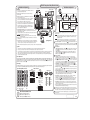
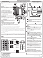
See the typical application diagram at right.
DVD
Menu
SMSNSM
Extron ISM 482
MENU
3. If desired, mount the ISM in a rack. Otherwise, affix the four rubber feet to the
bottom of the ISM in the four corners.
1
2
3
4
INPUTS
5
6
7
8
1
OUTPUTS
Video & Audio
Configuration
2
1
4. Connect up to 8 computer/RGB, component video, S-video, or composite video
source devices to the ISM's BNC inputs. See the input and output BNC
connections diagram below for cabling the various video formats.
5. Connect up to 8 stereo or mono sources to the ISM's captive screw audio inputs.
See the audio input connections diagram below to properly wire the connectors.
R/R-Y
R/R-Y
R/R-Y
R/R-Y
R/R-Y
R/R-Y
R/R-Y
R/R-Y
R
R
G/Y
VID
G/Y
VID
G/Y
VID
G/Y
VID
G/Y
VID
G/Y
VID
G/Y
VID
G/Y
VID
G
G
B/C
B-Y
B/C
B-Y
B/C
B-Y
B/C
B-Y
B/C
B-Y
B/C
B-Y
B/C
B-Y
B/C
B-Y
B
B
H/HV
H/HV
H/HV
H/HV
H/HV
H/HV
H/HV
H/HV
H/HV
H/HV
V
V
V
V
V
2
DVI OUT
V
1
V
V
2
3
V
4
V
5
6
7
ID PIN 4
ID PIN 11
BUFFERED LOCAL
MONITOR OUTPUT
H. SHIFT
RGB 109xi
VGA INTERFACE WITH ADSP
Laptop
Menu
ETHERNET
LAN/WAN
Network/
Internet
As necessary, press the Output 1 or Output 2 button to select the desired output. (Only one output can be selected at a time.)
3.
Press an input button to select a video and/or audio input for the selected output. The selected input is indicated by the solid green (for video) and/or red (for audio) Input
LED(s). Press the unselected output button to tie an input to that output or to view that tie. Both outputs' input selections can be viewed in the LCD display cycle.
4.
Use the LCD menu screens (see Main Menus and Operations at right), SIS commands, or the accompanying software program to configure the ISM inputs and outputs.
Refer to the ISM 482 User’s Manual for details.
•
•
•
Make picture adjustments (color [RGBcS, component, S-video, and composite video only] / tint [NTSC S-video and composite video only], contrast / brightness, size,
centering, and filter) to the input connected to the selected output by pressing the desired Picture Adjustments button and then rotating the Adjust
knob to adjust the setting
on the left side of the LCD screen or the Adjust knob to adjust the setting on the right side of the LCD screen. Press the unselected output button to select and make picture
adjustments to that output's connected input.
•
Auto Imaging
•
Auto imaging automatically sizes and centers the selected input. Execute the auto imaging feature for a specific input by pressing and holding the appropriate input button until
the LCD displays the message "Auto Image Input #n", releasing the input button, and then pressing and releasing the input button again.
Tip
Sleeve
G/Y
VID
G/Y
VID
G/Y
VID
G/Y
VID
G/Y
VID
B/C
B-Y
B/C
B-Y
B/C
B-Y
B/C
B-Y
B/C
B-Y
H/HV
H/HV
H/HV
H/HV
H/HV
V
V
V
V
V
Gnd
R
Balanced (high impedance)
Tip
Ring
Sleeve(s)
Tip
Ring
L
Gnd
R
Outputs
Unbalanced
L
CAUTION For unbalanced audio,
connect the sleeve(s)
to the ground contact.
DO NOT connect the
sleeve(s) to the
negative (-) contacts).
Balanced
RGBHV
Video
RGBS or RGsB or S-Video Composite
RGBcvS Component
Video
Video
Video
Extron Electronics, Anaheim, CA, USA
www.extron.com
USA 800.633.9876 • Europe +800.3987.6673
Asia +800.7339.8766 • Japan +81.3.3511.7655
China +400.883.1568 • Middle East +971.4.2991800
Tip
Ring
Sleeve (s)
Tip
Ring
5
Remote port
1
1
5
•
•
Gnd
R
L
Gnd
R
5
Exit Menu
Press Next to Exit
Next
NOTE
If you press the Menu button while a submenu is active, the next main menu will become active. For
example, the menu will change from the Input Configuration menu or submenus to the Output
Configuration main menu.
NOTE
To return to the default screens, let the ISM remain idle for 10 seconds until the selected screen
times out, or press the Menu button until the Exit Menu appears, then press the Next button.
9
6
Female
Pin
1
2
3
4
5
6-9
RS-232
—
TX
RX
—
Gnd
—
6
9
Male
Function
Not used
Transmit data
Receive data
Not used
Signal ground
Not used
Output resolution and refresh rate — The Adjust
knob selects the resolution for the selected output.
The Adjust knob selects the refresh rate. "Lock" indicates Accu-RATE Frame Lock™. The default is
1024 x 768 at 60 Hz.
Output sync and polarity — The Adjust
knob selects the sync format, RGBHV or RGBS, for the
selected output. The Adjust knob selects the polarity of the H and V output. The default values are
RGBHV, H Sync negative, and V Sync negative.
3 Advanced Configuration —
Picture Adjustments
R/R-Y
Menu
2 Output configuration —
2.
R/R-Y
10
sec.
knob selects the desired input video format
(RGB, RGBcvS, YUVi, YUVp, Betacam 50, Betacam 60, HDTV, S-video, or composite video). The Adjust
knob adjusts the input audio level in the range -15dB to +9dB. The default for each input is RGB video and
0dB audio level.
Select video and/or audio to switch by pressing the Video/Audio button as necessary to light the green Video LED and/or red Audio LED.
R/R-Y
10
sec.
1 Video & Audio Configuration — Select an input. The Adjust
PC
Tip
NO GROUND HERE.
Sleeve
Tip
NO GROUND HERE.
Advanced
Configuration
Use the Menu and Next buttons to navigate through the menu system. Use the Adjust knobs to make
configuration changes.
1.
Unbalanced (high impedance)
3
Menu
11. Plug the ISM and input and output devices into a grounded AC power source, and turn on the input and output devices.
L
User Presets
4
Operation
Audio Connections
Menu
1
RS-232
Typical application
10. If desired, plug an RJ-45 connector into the Ethernet port to connect the ISM to a LAN/WAN or
directly to a computer. For a network connection, wire the interface cable as a straight cable. For
connection to a computer or control system, wire the interface cable as a crossover cable.
R/R-Y
Output
Configuration
10 sec.
8
9. If desired, connect a PC or third-party control system to the ISM's RS-232 port. See the remote
port diagram below.
R/R-Y
2
Extron RGB 109xi
INPUT
8. Connect audio output devices, such as an audio amplifier or powered speakers. See the audio
output connections diagram below to wire the connectors.
CAUTION Incorrect audio connector wiring can damage the switcher. See the audio output
connections diagram below.
Tip
Sleeve
Menu
10 sec.
RS-232
LINK
ACT
7. If a DVI output board is installed, connect a DVI or HDMI (with a DVI-to-HDMI
adapter) compatible monitor or display to the rear panel DVI connector. The DVI connector
outputs the output 1 video signal.
Inputs
10 sec.
100- 240
50/60 Hz
1.2A MAX.
6. Connect displays and/or other output devices to the ISM's BNC and 15HD
outputs. See the RGBHV and RGBS examples on the input and output BNC
connections diagram below for cabling outputs.
Input and output BNC connections
Main Menus and Operation
Default
Cycle
Projector
Codec
2. If desired, install the optional DVI output card. Refer to the ISM 482 User’s
Manual for details.
Monitor
•
•
•
•
Test Pattern — Select a test pattern: Color Bars, cross hatch, 4 x 4 cross hatch, gray scale, crop,
alternating pixels, aspect ratio 1.78/1.85/2.35, or ramp. The Adjust
knob selects a test pattern. The
Adjust knob selects On or Off for either or both outputs to receive the test pattern. The default is both Off.
Blue Only Mode and Edge Smoothing — Rotate the Adjust
knob to select ( < > ) blue only mode On
or Off for either or both outputs. Rotate the Adjust knob to select the edge smoothing feature On or Off for
either or both outputs. Edge smoothing softens the edges of a picture by minimizing pixel differences.
Output Blanking — The Adjust
knob selects the number of top lines to blank. The Adjust knob
selects the number of bottom lines. Blanking masks noise on the top and bottom of a scaled image that
can result from processes such as captioning or tapehead switching.
RGB Delay — The Adjust
knob sets the RGB delay for the output 1 input selection from 0 seconds to 5
seconds in 0.1 second steps. The Adjust knob sets the RGB delay for the output 2 input selection. The
default for both outputs is 0.2 seconds.
Auto Imaging and Auto Memories — The Adjust
knob toggles auto imaging on and off for all input
selections. Auto imaging automatically sizes and centers each newly detected input. The Adjust knob
toggles the auto memories feature on and off for all input selections. Auto memories save and recall
centering, sizing, and filtering information for input rates, based on the frequency.
Enhanced Mode — Either Adjust knob toggles enhanced mode On or Off for either or both outputs.
Enhanced mode is an automatic gain control for S-video and composite video inputs.
Pixel Phase — The Adjust
knob sets the pixel phase adjustment for the input connected to output 1
from 0 to 31. The Adjust knob sets the pixel phase adjustment for the input connected to output 2.
Sampling at the optimum pixel phase results in a bright and stable scaled output. The default is 16.
PAL Film Mode — Either Adjust knob selects On or Off for the selected input. The PAL film mode (2:2
pulldown detection) should be used for a video source that is PAL video that originated from film. Select
other inputs as necessary to configure.
Reset — Resets the ISM to its factory default values. While the Reset submenu is active, press and hold
the Black/Mute button until the LCD displays the reset message.
4 User Presets — Three user presets per input are saved and erased from the Save Preset or Erase Preset
menu. Either knob selects ( < > ) among the presets. The Next button saves or erases the preset. N/A exits
without saving or erasing. (Recall user presets by repeatedly pressing the applicable Input button.)
5 Exit — Press the Next button to return to the default display cycle or press the Menu button to return to the
main menu system.
33-633-01 C
ISM 482 Integration Scaling Matrix Switcher
Installation and Operation
VCR
Installation
Default
Cycle
Projector
Codec
2. If desired, install the optional DVI output card. Refer to the ISM 482 User’s
Manual for details.
Monitor
Monitor
1. Ensure power is off to the ISM and all other devices that will be connected to it.
See the typical application diagram at right.
DVD
Menu
SMSNSM
Extron ISM 482
MENU
3. If desired, mount the ISM in a rack. Otherwise, affix the four rubber feet to the
bottom of the ISM in the four corners.
1
2
3
4
INPUTS
5
6
7
8
1
OUTPUTS
Video & Audio
Configuration
2
1
4. Connect up to 8 computer/RGB, component video, S-video, or composite video
source devices to the ISM's BNC inputs. See the input and output BNC
connections diagram below for cabling the various video formats.
5. Connect up to 8 stereo or mono sources to the ISM's captive screw audio inputs.
See the audio input connections diagram below to properly wire the connectors.
R/R-Y
R/R-Y
R/R-Y
R/R-Y
R/R-Y
R/R-Y
R/R-Y
R/R-Y
R
R
G/Y
VID
G/Y
VID
G/Y
VID
G/Y
VID
G/Y
VID
G/Y
VID
G/Y
VID
G/Y
VID
G
G
B/C
B-Y
B/C
B-Y
B/C
B-Y
B/C
B-Y
B/C
B-Y
B/C
B-Y
B/C
B-Y
B/C
B-Y
B
B
H/HV
H/HV
H/HV
H/HV
H/HV
H/HV
H/HV
H/HV
H/HV
H/HV
V
V
V
V
V
2
DVI OUT
V
1
V
V
2
3
V
4
V
5
6
7
RS-232
ID PIN 4
ID PIN 11
BUFFERED LOCAL
MONITOR OUTPUT
H. SHIFT
RGB 109xi
VGA INTERFACE WITH ADSP
Laptop
Menu
ETHERNET
As necessary, press the Output 1 or Output 2 button to select the desired output. (Only one output can be selected at a time.)
3.
Press an input button to select a video and/or audio input for the selected output. The selected input is indicated by the solid green (for video) and/or red (for audio) Input
LED(s). Press the unselected output button to tie an input to that output or to view that tie. Both outputs' input selections can be viewed in the LCD display cycle.
4.
Use the LCD menu screens (see Main Menus and Operations at right), SIS commands, or the accompanying software program to configure the ISM inputs and outputs.
Refer to the ISM 482 User’s Manual for details.
•
•
•
Make picture adjustments (color [RGBcS, component, S-video, and composite video only] / tint [NTSC S-video and composite video only], contrast / brightness, size,
centering, and filter) to the input connected to the selected output by pressing the desired Picture Adjustments button and then rotating the Adjust
knob to adjust the setting
on the left side of the LCD screen or the Adjust knob to adjust the setting on the right side of the LCD screen. Press the unselected output button to select and make picture
adjustments to that output's connected input.
•
Auto Imaging
•
Auto imaging automatically sizes and centers the selected input. Execute the auto imaging feature for a specific input by pressing and holding the appropriate input button until
the LCD displays the message "Auto Image Input #n", releasing the input button, and then pressing and releasing the input button again.
R/R-Y
R/R-Y
Tip
Sleeve
G/Y
VID
G/Y
VID
G/Y
VID
G/Y
VID
G/Y
VID
B/C
B-Y
B/C
B-Y
B/C
B-Y
B/C
B-Y
B/C
B-Y
H/HV
H/HV
H/HV
H/HV
H/HV
V
V
V
V
V
Gnd
R
Balanced (high impedance)
Tip
Ring
Sleeve(s)
Tip
Ring
L
Gnd
R
Outputs
Unbalanced
L
CAUTION For unbalanced audio,
connect the sleeve(s)
to the ground contact.
DO NOT connect the
sleeve(s) to the
negative (-) contacts).
Balanced
RGBHV
Video
RGBS or RGsB or S-Video Composite
RGBcvS Component
Video
Video
Video
Extron Electronics, Anaheim, CA, USA
www.extron.com
USA 800.633.9876 • Europe +800.3987.6673
Asia +800.7339.8766 • Japan +81.3.3511.7655
China +400.883.1568 • Middle East +971.4.2991800
Tip
Ring
Sleeve (s)
Tip
Ring
5
Remote port
1
1
5
•
•
Gnd
R
L
Gnd
R
5
Exit Menu
Press Next to Exit
Next
NOTE
If you press the Menu button while a submenu is active, the next main menu will become active. For
example, the menu will change from the Input Configuration menu or submenus to the Output
Configuration main menu.
NOTE
To return to the default screens, let the ISM remain idle for 10 seconds until the selected screen
times out, or press the Menu button until the Exit Menu appears, then press the Next button.
9
6
Female
Pin
1
2
3
4
5
6-9
RS-232
—
TX
RX
—
Gnd
—
6
9
Male
Function
Not used
Transmit data
Receive data
Not used
Signal ground
Not used
Output resolution and refresh rate — The Adjust
knob selects the resolution for the selected output.
The Adjust knob selects the refresh rate. "Lock" indicates Accu-RATE Frame Lock™. The default is
1024 x 768 at 60 Hz.
Output sync and polarity — The Adjust
knob selects the sync format, RGBHV or RGBS, for the
selected output. The Adjust knob selects the polarity of the H and V output. The default values are
RGBHV, H Sync negative, and V Sync negative.
3 Advanced Configuration —
Picture Adjustments
R/R-Y
Menu
2 Output configuration —
2.
R/R-Y
10
sec.
knob selects the desired input video format
(RGB, RGBcvS, YUVi, YUVp, Betacam 50, Betacam 60, HDTV, S-video, or composite video). The Adjust
knob adjusts the input audio level in the range -15dB to +9dB. The default for each input is RGB video and
0dB audio level.
Select video and/or audio to switch by pressing the Video/Audio button as necessary to light the green Video LED and/or red Audio LED.
Tip
NO GROUND HERE.
Sleeve
Tip
NO GROUND HERE.
10
sec.
1 Video & Audio Configuration — Select an input. The Adjust
PC
1.
Unbalanced (high impedance)
3
Advanced
Configuration
Use the Menu and Next buttons to navigate through the menu system. Use the Adjust knobs to make
configuration changes.
Operation
Audio Connections
Menu
Menu
LAN/WAN
Network/
Internet
11. Plug the ISM and input and output devices into a grounded AC power source, and turn on the input and output devices.
L
User Presets
4
Typical application
10. If desired, plug an RJ-45 connector into the Ethernet port to connect the ISM to a LAN/WAN or
directly to a computer. For a network connection, wire the interface cable as a straight cable. For
connection to a computer or control system, wire the interface cable as a crossover cable.
10 sec.
8
9. If desired, connect a PC or third-party control system to the ISM's RS-232 port. See the remote
port diagram below.
R/R-Y
2
Output
Configuration
Extron RGB 109xi
INPUT
8. Connect audio output devices, such as an audio amplifier or powered speakers. See the audio
output connections diagram below to wire the connectors.
CAUTION Incorrect audio connector wiring can damage the switcher. See the audio output
connections diagram below.
Tip
Sleeve
Menu
10 sec.
1
RS-232
LINK
ACT
7. If a DVI output board is installed, connect a DVI or HDMI (with a DVI-to-HDMI
adapter) compatible monitor or display to the rear panel DVI connector. The DVI connector
outputs the output 1 video signal.
Inputs
10 sec.
100- 240
50/60 Hz
1.2A MAX.
6. Connect displays and/or other output devices to the ISM's BNC and 15HD
outputs. See the RGBHV and RGBS examples on the input and output BNC
connections diagram below for cabling outputs.
Input and output BNC connections
Main Menus and Operation
•
•
•
•
Test Pattern — Select a test pattern: Color Bars, cross hatch, 4 x 4 cross hatch, gray scale, crop,
alternating pixels, aspect ratio 1.78/1.85/2.35, or ramp. The Adjust
knob selects a test pattern. The
Adjust knob selects On or Off for either or both outputs to receive the test pattern. The default is both Off.
Blue Only Mode and Edge Smoothing — Rotate the Adjust
knob to select ( < > ) blue only mode On
or Off for either or both outputs. Rotate the Adjust knob to select the edge smoothing feature On or Off for
either or both outputs. Edge smoothing softens the edges of a picture by minimizing pixel differences.
Output Blanking — The Adjust
knob selects the number of top lines to blank. The Adjust knob
selects the number of bottom lines. Blanking masks noise on the top and bottom of a scaled image that
can result from processes such as captioning or tapehead switching.
RGB Delay — The Adjust
knob sets the RGB delay for the output 1 input selection from 0 seconds to 5
seconds in 0.1 second steps. The Adjust knob sets the RGB delay for the output 2 input selection. The
default for both outputs is 0.2 seconds.
Auto Imaging and Auto Memories — The Adjust
knob toggles auto imaging on and off for all input
selections. Auto imaging automatically sizes and centers each newly detected input. The Adjust knob
toggles the auto memories feature on and off for all input selections. Auto memories save and recall
centering, sizing, and filtering information for input rates, based on the frequency.
Enhanced Mode — Either Adjust knob toggles enhanced mode On or Off for either or both outputs.
Enhanced mode is an automatic gain control for S-video and composite video inputs.
Pixel Phase — The Adjust
knob sets the pixel phase adjustment for the input connected to output 1
from 0 to 31. The Adjust knob sets the pixel phase adjustment for the input connected to output 2.
Sampling at the optimum pixel phase results in a bright and stable scaled output. The default is 16.
PAL Film Mode — Either Adjust knob selects On or Off for the selected input. The PAL film mode (2:2
pulldown detection) should be used for a video source that is PAL video that originated from film. Select
other inputs as necessary to configure.
Reset — Resets the ISM to its factory default values. While the Reset submenu is active, press and hold
the Black/Mute button until the LCD displays the reset message.
4 User Presets — Three user presets per input are saved and erased from the Save Preset or Erase Preset
menu. Either knob selects ( < > ) among the presets. The Next button saves or erases the preset. N/A exits
without saving or erasing. (Recall user presets by repeatedly pressing the applicable Input button.)
5 Exit — Press the Next button to return to the default display cycle or press the Menu button to return to the
main menu system.
33-633-01 C