1
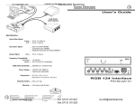
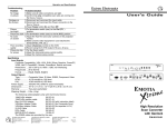
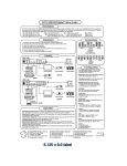
User Guide
H/HV
V
IN
OUT
ON
SYNC OUT
SHIFT LOCK
H/HV
TM
V
VS50 SL
SYNC INPUT
VIDEOSHIFT
TM
WITH SHIFTLOCK
TM
VS50 SL
P/N 60-211-01
EXTRON ELECTRONICS
1230 South Lewis Street
Anaheim, CA 92805
(714) 491-1500 FAX (714) 491-1517
U.S.A.
EXTRON ELECTRONICS, EUROPE
Beeldschermweg 6C
3821 AH Amersfoort
+31-33-453-4040 FAX +31-33-453-4050
The Netherlands
EXTRON ELECTRONICS, ASIA
41B Kreta Ayer Road
Singapore 089003
+65-226-0015 FAX +65-226-0019
Singapore
79-03
68-253-01
Rev. A2
VS50 SL Operation and Installation
VideoShift TM
ShiftLockTM
ShiftLockTM is a feature that enables synchronization of the VideoShiftTM
capability of two or more devices. Input and output ShiftLockTM connectors
allow VideoShiftTM devices to be connected (daisy-chained) enabling the
"Master" device to control VideoShiftTM for itself and all "Slave" devices.
VS50 SL Operation
The model VS50 SL Video Shifter includes both VideoShiftTM and
ShiftLockTM features. The operating characteristics of the VS50 SL are
controlled by the position of the six switches on the DIP switch module.
The DIP switches are externally accessible and the switch positions are
briefly defined in the table on the facing page. The following descriptions
and specifications are provided as an aid to understanding the operating
mode of the VS50 SL as a function of the DIP switch settings.
1. Original Sync Mode (DIP switch 2 (SW2) = ON):
A. When set for separate H&V out (SW3 = OFF):
a. If input = separate H&V,
H/HV out = H in,V out = V in
b. If input = composite sync (CS),
H/HV out = CS in, V out = V stripped from CS in
B. When set for Composite Sync out (SW3 = ON):
a. If input = separate H&V,
H/HV out = Composite sync, V out = Gnd
b. If input = Composite sync,
H/HV out = CS in, V out = Gnd
2. Processed Sync Mode (SW2 = OFF):
A. When set for separate H&V out (SW3 = OFF):
H/HV out = H processed, V out = V processed
B. When set for CS out (SW3 = ON):
H/HV out = Composite sync, V out = Gnd
3. Output sync polarity:
A. Output sync is negative when CS output selected (SW3 = OFF)
B. Output sync is negative when Negative sync selected (SW1 = ON)
C. Follow input polarity when Follow Input is selected (SW1 = OFF)
(Note: For CS input, both H&V sync will be negative)
4. Processed sync timing specifications:
A. Delay from original sync (Shift Function = disable [SW4 = ON]):
75 micro-seconds for Vertical Sync
310 nano-seconds for Horizontal Sync
B. Shifting range (from Shift Function = enable position [SW4 =OFF]):
±20 micro-seconds for Vertical Sync
±25 nano-seconds for Horizontal Sync
5. Shift timing specifications:
A. Shift Mode = Test (SW5 = ON) = 4 seconds/rotation
B. Shift Mode = Normal (SW5 = OFF) = 5 minutes/rotation
Extron • VS50 SL • User’s Guide
H/HV
V
H/HV
VideoShiftTM is a technique in which the displayed video image is slowly
shifted horizontally and vertically in a clockwise (rotating) direction.
Gradually shifting the position of the video image in this manner reduces
"burn-in" damage to the CRT which can occur when intense images are
allowed to remain in the same position for extended periods.
Page 1
VS50 SL Operation and Installation
V
IN
OUT
ON
VS50 SL
TM
SYNC INPUT
VIDEOSHIFT
WITH SHIFTLOCK
TM
SHIFT LOCK
SYNC OUT
TM
DIP Switch Setting
DIP Switch positions are defined in the table
below.
Abbreviations: CSync = Composite Sync
H = Horizontal, V = Vertical
Switch
1
2
3
4
5
6
Description
Output Sync Polarity
Original/Processed Sync
H/HV BNC Sync
Shift Function
Shift Mode
Operating Mode
ON
ON
Negative
Original
CSync
Disable
Test
Slave
OFF ¬
Follow Input
Processed
H Only
Enable
Normal
Master
Connecting the VS50 SL Input, Output and ShiftLock Cables
Use the diagram below as an aid to connecting input, output and
ShiftLockTM cables to the VS50 SL Video Shifter. The video (RGB)
cables are routed directly from the source to the destination device.
However,the sync cables must be routed through the VS50 SL as shown
in the diagram. If connecting more than one VS50 SL, the ShiftLockTM
connectors may be connected to allow a Master/Slave setup as shown
in the upper left corner of the diagram.
Extron • VS50 SL • User’s Guide
Page 2