1
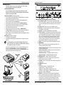
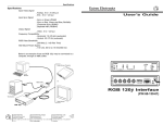
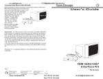
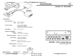
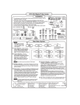
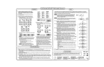
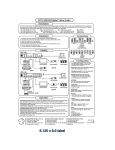
Operation and Specifications
Troubleshooting
Problem
No image
or picture
Probable Solution
1) Make sure all cable connections are tight.
2) Confirm that only compatible scan rates are coming into
the EMOTIA XTREME.
Garbage on
1) Disconnect and reconnect the input cable.
the Screen
2) Disconnect and reconnect the Power connector on the
EMOTIA XTREME.
3) Press Freeze button On and then Off.
Picture
1) Put termination switch (rear) to the Out (75Ω)
too bright
position.
Picture too dark 1) Put termination switch (rear) to the In (Hi Z) position.
No Color
1) Adjust the Hue/Tint and Color controls on the projector/
on screen
monitor.
2) Make sure the video equipment in use matches the
format (NTSC, PAL etc.).
Poor recording 1) Adjust sharpness control on the VCR.
quality
2) Record using the S-VHS output of EMOTIA XTREME.
Picture too big 1) Try the Zoom switch.
for screen
2) Adjust the Horizontal sizing control (width).
3) Adjust the Vertical sizing control.
User's Guide
Specifications
Input Signals
Computer Compatibility: VGA, XGA, SUN, Silicon Graphics, PowerPC,
VESA, NeXT, PowerMAC, Quadra, PowerBook, Radius and more.
Resolutions .... 320 x 200 up to 1600 x 1280, non-interlacing
Frequencies ... 29 to 92 kHz
Format ............ RGsB, RGBS, RGBHV
Output Signals
Type ................ Composite Video, S-Video, RGBS, Component Video
NTSC .............. 15.75 kHz/60 Hz, 525 lines
PAL ................. 15.63 kHz/50 Hz, 625 lines
Power Supply ........ 100/240 VAC 50/60 Hz (auto-switchable)
Dimensions ............ 10" W x 11.5" D x 1.5" H (25 W x 29 D x 3.8 H cm)
Warranty ................ Two years parts/labor
Shipping Weight .... 9 lbs. (4 kg)
The following cables/adapters ship with the Emotia Xtreme:
13W3/VGA adapter
26-372-01
13W3/VGA monitor cable
26-371-01
Mac HV/VGA Adapter
26-374-05 (with instruction label)
VGA/Mac Adapter Cable
26-340-01 (for Composite Sync)
VGA/Mac Adapter Cable
26-340-02 (for separate H & V)
S-VHS Cable
26-316-02
RCA Cable
26-345-01
BNC/M-RCA/F Adapter
10-264-01
The RGBS cables are provided by the user.
SM
EXTRON ELECTRONICS
1230 S. Lewis Street
Anaheim, CA 92805
(714) 491-1500 FAX (714) 491-1517
U.S.A.
EXTRON ELECTRONICS, EUROPE
Beeldschermweg 6C
3821 AH Amersfoort
+31-33-453-4040 FAX +31-33-453-4050
The Netherlands
EXTRON ELECTRONICS, ASIA
41B Kreta Ayer Road
Singapore 089003
+65-226-0015 FAX +65-226-0019
Singapore
69-12
68-302-01
Rev. A
High Resolution
Scan Converter
with Genlock
P/N 60-218-01
Installation & Operation
Installation & Operation
Extron EMOTIA Xtreme
The Emotia Xtreme does not have a power switch. Make all cable
connections before connecting the power cable.
Connecting the EMOTIA Xtreme
Use the following instructions along with the panel drawings and
descriptions on the facing page and the application diagram below as
a guide to connecting the cables.
VGA PC'S and SUN/SGI (All cables are included)
1. Turn the computer and its monitor Off. In a SUN/SGI application, connect the
provided adapters and proceed to next step.
2. Connect the input cable's (26-112-15) male end to the computer and the
female end to the Emotia Xtreme CPU Input (J).
3. Use the computer monitor's cable to connect to the Monitor Output (H).
4. Connect the desired output cable (Composite, S-VHS, RGBS (for RGBS or
Component video)(L) to the output device's input connector.
5. Turn computer and monitor power On.
6. Plug the 5-pin din cable from the power supply to POWER INPUT (K).
7. Use EMOTIA XTREME'S Horizontal Centering, Vertical Centering, Horizontal Size
and Vertical Size controls (G) to align the image on the screen.
8. Set the remaining front panel switches as required (use descriptions on facing
page to assist you).
MAC Systems (All cables are included)
1. Turn the MAC and its monitor Off.
2. Connect the Mac/VGA Adapter to the Mac computer - configured for desired
scan rate.
__ In a Mac application, set the Mac/VGA Adapter switches for the
monitor being used. This is shown on the adapter label. Composite
Sync outputs only if Mac 13” is selected.
Connect the Input Cable (PN# 26-112-15) from the Mac/VGA Adapter to the
CPU Input on the Emotia Xtreme. Use the appropriate output cable to
connect the Mac monitor to the Monitor Output on the Emotia Xtreme. (Use
diagram below and follow steps 4 through 8 above.)
1
Extron • EMOTIA Xtreme • User’s Guide
EMOTIA Xtreme Front and Rear Panels (see panel drawings above)
A. Freeze Button and LED – The Freeze Button is a momentary switch.
Press it once to freeze the display on a frame; press it again to release the
display. This LED lights when the Emotia Xtreme is in the Freeze Frame
mode.
B. Power On LED – This LED is on if power is applied to the unit.
C. Anti Flicker – Six levels of anti-flicker are built into the Emotia Xtreme.
Set switches for minimum flicker.
D. PAL/NTSC – This switch selects between two output formats.
E. Genlock Controls – If using Genlock, the two switches combine to make
a coarse phase setting between the video output signal and the Genlock
signal. These switch settings provide for 0º (in phase), or delayed by 90º,
180º, or 270º (both switches down) after the Genlock signal. The SCØ
control is used to "fine-tune" this phase between Genlock sub-carrier
(color burst) and the output video. The HØ control is used to adjust the
phase between the Genlock Sync and the Output Video Sync.
F. Memory – Store up to 21 sizing and positioning settings for later recall.
G. IMAGE/ZOOM
Zoom – Use sizing controls to adjust magnification up to 200%. Use
centering controls to pan around image.
Horizontal Centering Control – This control moves the picture to the left
or right on the display screen.
Vertical Centering Control – Rotating this control moves the position of
the picture up or down on the screen.
Horizontal Size Control – This adjusts the width of the picture.
Vertical Size Control – This adjusts the height of the picture.
H. MONITOR OUTPUT – Female 15-pin VGA style connector.
Ω Switch – Set to HI-Z if an output monitor is connected, 75Ω
I. HI-Z/75Ω
position if no output monitor is connected.
J. CPU INPUT – Male 15-pin VGA style connector. Monitor output from CPU
connects here.
K. POWER INPUT connector
L. Outputs:
VIDEO (BNC connector) – Composite video output
S-VIDEO connector – S-Video (S-VHS) output
RGBS Switch – Selects RGBS or Component video output.
RGB Output (4 BNC connectors) – RGBS/Component video output
depending on position of RGBS switch.
M. GENLOCK – Genlock IN and OUT BNC connectors and impedance
switch. The Genlock source must be connected to the BNC marked "In".
The Genlock Out connector allows the signal to be passed on to another
video device. If 75Ω termination is provided elsewhere (at a device
connected to Genlock Out, for example), put the switch to the HI Z
position. If there is no other Genlock termination, set the switch to 75Ω.
Extron • EMOTIA Xtreme • User’s Guide
2