1
LBI-39101
INTERCONNECTING THE EQUIPMENT
PERSONAL COMPUTER
Dispatch Keyboard
PC-To-Enhanced Audio Enclosure Serial Data
Interconnect Cable
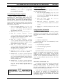
The Dispatch Keyboard interfaces to the console system
via the Enhanced Audio Enclosure. This keyboard's part
number is P29/7590182003 (350A1371P17). It is
sometimes referred to as the "custom keyboard".
The PC-to-Enhanced Audio Enclosure RS-232 serial
data link uses cable P29/5010150000 (350A1371P29). This
cable has a female DB-9 connector on one end for mating to
the PC's male DB-9 serial COM port connector. The cable's
other end has a male DB-9 connector for mating to the
female DB-9 connector labeled "PC" at the Enhanced
Audio Enclosure. The cable is nine (9) feet long. It should
not be modified in any way and "extension" cables are not
recommended for this 19.2k baud serial link. Identical
cables are also used between the Enhanced Audio Enclosure
and the Speaker Assemblies.
q
Mate the cable's female DB-9 connector to the PC's
male DB-9 serial COM port connector used for
Enhanced Audio Enclosure interfacing. Normally,
the COM2 port is used. Mate the other end of the
cable to the Enhanced Audio Enclosure's DB-9
connector labeled "PC". This interconnection is
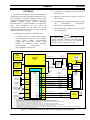
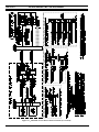
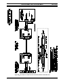
shown in Figure 1 but not in Figure 6.
q
NOTE
Do not over-tighten the screws on the DB-style
connectors.
Desk Mic (if used)
q
Standard PC Keyboard
During dispatch operations, the standard PC keyboard is
not used. However, during the console set-up process,
access to this keyboard will be required:
•
for
file
management
(for
example
AUTOEXEC.BAT and CONFIG.SYS file changes
may be necessary)
•
to configure certain items via the Editor program
(see LBI-39056 for details)
•
to start the console's application program
q
Connect the standard PC keyboard to the PC in
accordance with the manufacturer's instructions.
The plug on the keyboard's cable mates with a
connector on the back of the PC.
Video Display Monitor
q
Interconnect the video display monitor's video
cable to the Personal Computer in accordance with
the manufacturer's instructions.
ENHANCED AUDIO ENCLOSURE
All Enhanced Audio Enclosure interconnections are
made at the rear panel of the enclosure. Secure the cables
with cable ties as necessary.
18
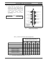
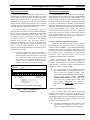
Connect the Dispatch Keyboard to the Enhanced
Audio Enclosure by plugging its male DB-9
connector to the female DB-9 connector on
Enhanced Audio Enclosure's rear panel. On the rear
panel, this connector is labeled "KBD". Its pin-out
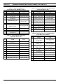
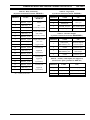
is indicated in Table 24.
Connect the desk microphone (option CRMC3D or
equivalent) to the Enhanced Audio Enclosure by
mating its male DB-9 connector to the female DB-9
connector labeled "DESK MIC" on the Enhanced
Audio Enclosure's rear panel. The desk mic's cable
is five (5) feet (1.52 meters) long. The DB-9's pinout is shown in Table 15. Observe the microphone
priority NOTE in the following section; the desk
mic has the lowest priority.
Headset Jacks (if used)
q
q
At the selected location, secure each headset jack
box (part of option CRCN1W or equivalent) to the
mounting surface using the four (4) #10 threadforming screws supplied in the installation kit or
use alternate hardware if required (not supplied).
Before mounting, verify adequate clearance is
maintained for the headset's plugs. If using both
jack boxes, label them "SUPERVISOR" and
"OPERATOR".
Connect each headset jack box to the Enhanced
Audio Enclosure using the 6-foot (1.83 meters)
cable supplied. This cable (part number
19C337102P1 supplied with CRCN1W) has male
DB-9 connectors on both ends. One end mates with
the female DB-9 connector at a jack box and the
other end mates to the female DB-9 connector at
the Enhanced Audio Enclosure's rear panel. The
connectors on the rear panel are labeled "SUPER
H/S" and "OPER H/S" for the supervisor and
operator headsets respectively. Interconnect the
cables accordingly. The DB-9 connectors' pin-outs
are indicated in Tables 16 and 17.