1
Bulletin 71.2:LR125
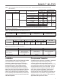
Table 1. Type LR125 Main Valve Body Sizes, End Connection Styles, Structural Design Ratings and Maximum Operating
Inlet Pressures(1)
MAIN VALVE BODY SIZE
In.
MAIN VALVE
BODY MATERIAL
DN
psig
25, 50, 80 and 100
CF8M Stainless steel
MAXIMUM OPERATING
INLET PRESSURE(3)
bar
psig
bar
1500
103
300
20.7
290
20.0
290
20.0
CL300 RF
750
51.7
300
20.7
NPT or SWE
(1 and 2 in. only)
CL150 RF
WCC Steel
1, 2, 3 and 4
STRUCTURAL DESIGN
RATING(3)
END CONNECTION STYLE(2)
CL600 RF
1500
103
PN 16/25/40 RF(4)
NPT
(1 and 2 in. only)
CL150 RF
580
40.0
1440
99.2
300
20.7
275
19.0
275
19.0
CL300 RF
720
49.6
CL600 RF
1440
99.2
300
20.7
PN 16/25/40 RF(4)
580
40.0
1. The pressure/temperature limits in this Bulletin and any applicable standard or code limitation should not be exceeded.
2. Ratings and end connections for other than ASME standard can usually be provided. Contact your local Sales Office for assistance.
3. Maximum cold working pressure (CWP) per ASME B16.34 or product Bulletin limit, whichever is lowest. Temperature may decrease these maximum pressures.
4. Not available for 4 in. / DN 100 body size.
Table 2. Type MR95H Pilot Maximum Cold Working Pressure(1)(2)
BODY SIZE
BODY AND SPRING CASE MATERIAL
Steel
Stainless steel
1/2 NPT
MAXIMUM INLET PRESSURE
300 psig / 20.7 bar
300 psig / 20.7 bar
MAXIMUM OUTLET PRESSURE
300 psig / 20.7 bar
300 psig / 20.7 bar
1. The pressure/temperature limits in this Bulletin, and any applicable standard or code limitation should not be exceeded.
2. Temperature and/or the body end connection may decrease these maximum pressures.
Table 3. Outlet (Control) Pressure Ranges
PILOT
Type MR95H
OUTLET PRESSURE RANGE
SPRING WIRE DIAMETER
SPRING FREE LENGTH
psig
bar
In.
mm
In.
mm
SPRING PART NUMBER
AND COLOR
15 to 30
25 to 75
70 to 150
1.0 to 2.1
1.7 to 5.2
4.8 to 10.3
0.207
0.234
0.283
5.26
5.94
7.19
2.50
2.60
2.44
63.5
65.9
62.0
ERCA04288A0 Yellow
ERAA01910A0 Green
ERAA01911A0 Red
Table 4. Diaphragm Material Selection Information
Liquid Temperature
General Applications
17E68 NITRILE (NBR)
17E97 NITRILE (NBR)
17E88 FLUOROCARBON (FKM)
-20 to 150°F / -29 to 66°C
0 to 150°F / -18 to 66°C
0 to 250°F / -18 to 121°C(1)
Best for low pressure
differential and cold temperature
service applications.
Best for abrasive or
erosive service applications.
Best for high temperature
applications.
Fair
Excellent
Good
Heavy Particle Erosion
1. Fluorocarbon (FKM) is limited to 200°F / 93°C in hot water.
Installation
Overpressure Protection
The robust design of the Type LR125 allows this regulator
to be installed indoors or outdoors. This regulator
is designed to withstand the elements. The powder
paint coating protects regulator against minor impacts,
abrasions and c orrosion. When installed outdoors,
the Type LR125 does not require protective housing.
However, the Type MR95H pilot should be oriented so
that the pilot spring case vent is pointed down. Otherwise,
make sure the vent is protected so that rain, moisture,
insects or any debris will not accumulate inside or block
the vent assembly. When installed indoors, install remote
venting of the pilot spring case as required by applicable
codes and regulations.
Overpressuring any portion of a regulator or associated
equipment may cause personal injury, leakage
or property damage due to bursting of pressurecontaining parts. Provide appropriate pressure relieving
or pressure limiting devices to ensure that the limits in
the Specifications section are not exceeded. Common
methods of external overpressure protection include
relief valves, monitoring regulators, shutoff devices
and series regulation. Regulator operation within
ratings does not prevent the possibility of damage from
external sources or from debris in the pipeline. Install
additional strainer or filter upstream of the regulator for
applications with high levels of debris.
5