1
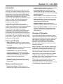
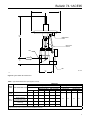
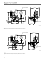
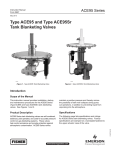
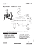
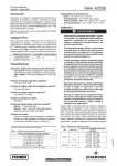
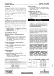
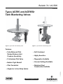
Bulletin 74.1:ACE95 October 2014 Types ACE95 and ACE95Sr Tank Blanketing Valves W9133 W8155 Figure 1. Type ACE95 Tank Blanketing Valve Figure 2. Type ACE95Sr Tank Blanketing Valve Features • Fully Balanced Pilot Design Reduces Inlet Pressure Sensitivity • Self-Contained • Frictionless Pilot Valve • Diagnostics Available • Bubble Tight Shutoff • Vacuum Settings Available • Pilot Controlled • Stainless Steel Construction Available • highly Sensitive D102720X012 • Angled or In-Line Body Option www.fisherregulators.com Bulletin 74.1:ACE95 Specifications The Specifications section lists the specifications for Types ACE95 and ACE95Sr Tank Blanketing Valves. Factory specification is stamped on the nameplate fastened on the valve at the factory. Sizes and End Connection Styles Type ACE95 Angled Body(1): 3/4 NPT 1 NPT NPS 1 / DN 25, CL150 RF NPS 1 / DN 25, CL300 RF NPS 1 / DN 25, PN 16/25/40 RF NPS 1 / DN 25, Sanitary Flange In-Line Body: 3/4 NPT 1 NPT NPS 1 / DN 25, CL150 RF NPS 1 / DN 25, CL300 RF NPS 1 / DN 25, PN 16/25/40 RF NPS 1 x 2 / DN 25 x 50, CL150 RF NPS 1 x 2 / DN 25 x 50, PN 16/25/40 RF NPS 1 / DN 25, Sanitary Flange Type ACE95Sr Angled Body(1): 2 NPT NPS 2 / DN 50, CL150 RF NPS 2 / DN 50, CL300 RF Maximum Operating Inlet Pressure(2) 200 psig / 13.8 bar Maximum Emergency Outlet (Casing) Pressure(2) 20 psig / 1.4 bar Maximum Operating Outlet Pressure(2) 1.5 psig / 0.10 bar Outlet Pressure Ranges -5 in. w.c. to 1.5 psig / -12 to 0.10 bar Minimum and Maximum Differential Pressures(2) Minimum: 25 psi / 1.7 bar Maximum: Up to 200 psi / 13.8 bar depending on main valve spring (See Table 6) Main Valve Flow Characteristic Linear Pressure Registration External Accuracy Typically within 0.5 in. w.c. / 1 mbar when flowing 5 to 70 percent of advertised capacities Temperature Capabilities(2) Nitrile (NBR): -20 to 180°F / -29 to 82°C Fluorocarbon (FKM): 0 to 212°F / -18 to 100°C Ethylenepropylene (EPDM - FDA): -20 to 212°F / -29 to 100°C Perfluoroelastomer (FFKM): -20 to 212°F / -29 to 100°C IEC Sizing Coefficients Type ACE95(3): XT: 0.72 FD: 0.40 FL: 0.89 Km: 0.79 Flow Coefficients for Relief Valve Sizing Type ACE95: Type ACE95Sr: Cv 1 use Cv 1.1 Cv 20 use Cv 22 Cv 2 use Cv 2.2 Cv 45 use Cv 50 Cv 4 use Cv 4.4 Cv 60 use Cv 66 Cv 7.5 use Cv 9.25 Cv 10 use Cv 11 Construction Materials Body: CF3M/CF8M Stainless steel Trim: 304 Stainless steel and 316 Stainless steel Elastomers: Nitrile (NBR), Fluorocarbon (FKM), FDA-Ethylenepropylene (FDA-EPDM) or Perfluoroelastomer (FFKM) Diaphragm: Polytetrafluoroethylene (PTFE) Actuator: 316 Stainless steel or Carbon steel Approximate Weights (with all accessories) Type ACE95: 40 lbs / 18 kg Type ACE95Sr: 60 lbs / 27 kg 1. Various Single Array Manifold (SAM) tank connections are also available. Contact your local Sales Office for more information. 2. The pressure/temperature limits in this Bulletin or any applicable standard limitation should not be exceeded. 3. For NPS 1 / DN 25 body size, all trims. 2 Type ACE95Sr: XT: 0.72 FD: 0.46 FL: 0.89 Km: 0.79 Bulletin 74.1:ACE95 Introduction • Control Pressure Gauge—Low-pressure gauge to measure control pressure (tank pressure). Tank blanketing is the process of using a gas, such as nitrogen, to maintain a slightly positive pressure in an enclosed storage tank. Tank blanketing prevents a stored product from vaporizing into the atmosphere, reduces product combustibility and prevents oxidation or contamination of the product by reducing its exposure to air. Tank blanketing is utilized with various products, including: adhesives, pharmaceuticals, pesticides, fertilizers, fuels, inks, photographic chemicals and food additives. • Purge Meter (Rotameter)—Maintains a small amount of flow through the sensing and/or main line. Prevents corrosive tank vapors from damaging upstream equipment. Types ACE95 and ACE95Sr valves are selfcontained, fully balanced, pilot-operated and are used for accurate pressure control on tank blanketing systems. These valves help control emissions and provide protection against atmospheric contamination. Types ACE95 and ACE95Sr valves maintain a positive tank pressure which reduces the possibility of tank wall collapse during pump out operations, prevents stored product from vaporizing to atmosphere. The Type ACE95Sr uses an angled body in either a 2 NPT, CL150 RF or CL300 RF and is taller than the Type ACE95. Features and Benefits • Pilot Controlled—ACE95 Series valves are pilot operated which results in a high degree of accuracy and control. • Fully Balanced Pilot—Eliminates setpoint changes caused by variations in inlet pressure. • Large Actuator—Large actuator diaphragm increases sensitivity to tank pressure changes. • Rolling Pilot Diaphragm—The rolling diaphragm balances the pilot valve and eliminates friction, resulting in extremely accurate control. • Diagnostic Port—Allows field analysis of valve operation, simplifying maintenance and reducing service costs. Options and Accessories • Pressure Switch—Allows installation of an alarm system to indicate low or high-pressure on the tank. • Outlet Check Valve—Prevents corrosive gases and vapors from flowing back into the blanketing system through the delivery line. • Diagnostic Gauge—Allows analysis of valve operation in the field, simplifying service and reliability. • Single Array Manifold (SAM)—Provides sense line connection and main valve connection through a single tank nozzle. (Not compatible with In-Line end connection). Principle of Operation Types ACE95 and ACE95Sr tank blanketing valves control the vapor space pressure over a stored liquid. When liquid is pumped out of the tank or vapors in the tank condense, the pressure in the tank decreases. Tank pressure is sensed by the large actuator diaphragm. When tank pressure is less than the valve set pressure, spring force moves the actuator diaphragm downward. When the actuator moves downward, it pushes open the pilot valve which allows loading pressure to flow into the tank. As loading pressure decreases, inlet pressure is able to overcome the force of the main valve spring, opening the main valve. See Figure 3. When pressure in the tank increases above setpoint, the large actuator diaphragm is pushed upward, allowing the pilot to close. Loading pressure equalizes with inlet pressure closing the main valve. The pilot valve is balanced (inlet pressure creates equal upward and downward force on these components); therefore, the outlet pressure of the unit is not affected by fluctuating inlet pressure. • Inlet Pressure Gauge—Displays pressure of blanketing gas supply to the tank blanketing valve. 3 Bulletin 74.1:ACE95 Valve Closed Valve open Inlet pressure Tank pressure Atmospheric pressure Inlet bleed pressure Figure 3. Type ACE95 Operational Schematic 4 Bulletin 74.1:ACE95 Diagnostics Thermal Equations Tank blanketing valves are often installed in locations that are difficult to access. Types ACE95 and ACE95Sr valves are available with a diagnostics feature that allows analysis of valve operation in the field, making maintenance easier and more reliable. For tanks up to 840,000 gallons / 3179 m3 capacity, use one of the following equations: The diagnostics feature uses the relationship between pressure in the pilot and main valve chambers to analyze valve performance. Equation 2: Sizing Methods Direct Displacement The direct displacement method should be used with extreme caution. The direct displacement method determines the amount of blanketing gas required to replace liquid pumped out of the tank. Direct displacement does not allow for fluctuating temperature or other factors that may affect pressure in the vapor space. This method is typically applied to tanks operating at constant temperature and containing non-flammable, non-volatile products. Qtotal = Qpump where, Qtotal = Required Flow Rate Qpump = Required Flow Rate to replace pumped out liquid from Table 1 API 2000 The American Petroleum Institute Standard 2000 (API 2000) sizing method accounts for liquid pump-out as well as contraction of tank vapors due to cooling. When using API methods: where, Qtotal = Qpump + Qthermal Qtotal = Required Flow Rate Qpump = Required Flow Rate to replace pumped out liquid from Table 1 Qthermal = Required Flow Rate due to thermal cooling. See Thermal Equations 1 to 4 below or Table 2. Equation 1: Qthermal [scfh Air] = Vtank x 0.0238 Qthermal [scfh Nitrogen] = Vtank x 0.0238 x 1.015 Equation 3: Qthermal [Nm3/h Air] = Vtank x 0.169 Equation 4: Qthermal [Nm3/h Nitrogen] = Vtank x 0.169 x 1.015 where, For Equations 1 and 2: Vtank = tank volume, gallons For Equations 3 and 4: Vtank = tank volume, m3 For tanks greater than 840,000 gallons / 3179 m3 capacity: See Table 2. Depending on the method, there can be a significant difference in the calculated required capacity. No matter which method is used, the tank must be equipped with supplemental venting to protect the tank, product and personnel in cases of equipment failure, fire exposure or other conditions that could cause the tank pressure or vacuum to exceed operating limits. Capacity Information Capacity information (Tables 2, 3, 4 and 5) are based on 0.97 specific gravity nitrogen. Nitrogen is the most common blanketing gas. Should you use a different gas, convert the tabular values as follows: For blanketing (pad) gases other than nitrogen, multiply the given nitrogen flow rate values by the conversion factors in Table 3. For gases of other specific gravities, multiply the given nitrogen flow rate by 0.985 and divide by the square root of the appropriate specific gravity. 5 Bulletin 74.1:ACE95 Table 1. Flow Rate Conversion(1) Multiply maximum pump rate OUT: By To obtain(1): U.S. GPM U.S. GPH m3/hr 8.021 0.1337 1.01 SCFH SCFH Nm3/h Barrels/hr Barrels/day 5.615 0.2340 SCFH SCFH 1. Gas flow of blanketing gas to replace liquid pumped out. Table 2. API 2000 Requirements for Thermal Venting Capacity for Tanks Larger than 840,000 gallons / 20,000 barrels / 3179 m3 Tank Capacity In Breathing (Vacuum), scfh / Nm3/h OF air Gallons m3 scfh 1,050,000 4000 24,000 643 1,260,000 5000 28,000 750 Nm3/h 1,470,000 6000 31,000 831 1,680,000 7000 34,000 911 1,890,000 8000 37,000 992 2,100,000 9000 40,000 1072 2,520,000 10,000 44,000 1179 2,940,000 11,000 48,000 1286 3,360,000 13,000 52,000 1394 3,780,000 14,000 56,000 1501 4,200,000 16,000 60,000 1608 5,040,000 19,000 68,000 1822 5,880,000 22,000 75,000 2010 6,720,000 25,000 82,000 2198 7,560,000 29,000 90,000 2412 Table 3. Conversion Factors (for converting Nitrogen flow rates to other gas flow rates) BLANKET GAS SPECIFIC GRAVITY CORRECTION FACTOR Natural Gas 0.60 1.270 Air 1.00 0.985 Dry CO2 1.52 0.797 0.985 Correction Factor = SG Table 4. Type ACE95 Capacities CAPACITIES IN SCFH / Nm3/h OF NITROGEN INLET PRESSURE psig CV = 1 kPa SCFH CV = 2 Nm3/h SCFH CV = 4 Nm3/h CV = 7.5 Nm3/h SCFH Nm3/h CV = 10 SCFH Nm3/h kg/cm2 25 1.7 1.76 172 1130 30.3 2300 61.6 4440 119 9900 265 11,200 300 30 2.1 2.11 207 1280 34.3 2670 71.6 5020 135 11,200 300 13,000 348 40 2.8 2.81 276 1680 45.0 3440 92.2 6780 182 13,500 362 16,400 440 50 3.5 3.52 345 2050 54.9 4090 110 8140 218 17,800 477 20,200 541 60 4.1 4.22 414 2330 62.4 4800 129 9370 251 18,200 488 22,700 608 70 4.8 4.92 483 2670 71.6 5450 146 10,600 284 23,600 632 26,600 713 80 5.5 5.62 552 3010 80.7 6160 165 12,000 322 27,400 734 30,800 825 90 6.2 6.33 621 3410 91.4 6840 183 13,200 354 30,800 825 34,100 914 - continued - 6 SCFH bar Bulletin 74.1:ACE95 Table 4. Type ACE95 Capacities (continued) CAPACITIES IN SCFH / Nm3/h OF NITROGEN INLET PRESSURE CV = 1 CV = 2 CV = 4 CV = 7.5 CV = 10 psig bar kg/cm2 kPa SCFH Nm3/h SCFH Nm3/h SCFH Nm3/h SCFH Nm3/h SCFH Nm3/h 100 6.9 7.03 690 3690 98.9 7430 199 14,600 391 34,100 914 38,000 1018 110 7.6 7.73 758 4000 107 8110 217 16,000 429 36,800 986 41,300 1107 120 8.3 8.44 827 4370 117 8750 235 17,200 461 38,800 1040 44,600 1195 130 8.9 9.14 896 4590 123 9340 250 18,300 490 43,400 1163 46,300 1241 140 9.6 9.84 965 4930 132 10,100 271 19,500 523 46,500 1246 50,500 1353 150 10.3 10.55 1034 5300 142 10,800 289 21,000 563 49,900 1337 54,500 1461 160 11.0 11.25 1103 5640 151 11,400 306 21,500 576 53,200 1426 58,200 1560 170 11.7 11.95 1172 5950 159 12,000 322 23,000 616 55,800 1495 62,300 1670 180 12.4 12.65 1241 6320 169 12,600 338 24,700 662 59,600 1597 65,900 1766 190 13.1 13.36 1310 6630 178 13,400 359 25,600 686 62,600 1678 69,600 1865 200 13.8 14.06 1379 6970 187 14,000 375 27,200 729 65,100 1745 71,900 1927 Table 5. Type ACE95Sr Capacities CAPACITIES IN SCFH / Nm3/h OF NITROGEN INLET PRESSURE CV = 20 CV = 45 CV = 60 psig bar kg/cm2 kPa SCFH Nm3/h SCFH Nm3/h SCFH Nm3/h 25 1.7 1.76 172 26,700 716 60,200 1613 80,000 2144 30 2.1 2.11 207 30,200 809 68,100 1825 90,800 2433 40 2.8 2.81 276 37,500 1005 84,500 2265 112,700 3020 50 3.5 3.52 345 45,700 1225 102,800 2755 137,100 3674 60 4.1 4.22 414 53,800 1442 121,000 3243 161,400 4325 70 4.8 4.92 483 61,800 1656 139,200 3731 185,600 4974 80 5.5 5.62 552 69,900 1873 154,400 4138 209,800 5623 90 6.2 6.33 621 78,000 2090 175,500 4703 234,000 6271 100 6.9 7.03 690 86,000 2305 193,600 5188 258,200 6920 125 8.6 8.79 862 102,100 2736 238,900 6402 306,500 8214 150 10.3 10.55 1034 126,300 3385 284,200 7616 378,900 10,154 175 12.1 12.31 1207 142,400 3816 329,400 8828 427,200 11,449 200 13.8 14.06 1379 166,500 4462 347,700 9318 499,600 13,390 Table 6. Minimum and Maximum Differential Pressures Body size nps 3/4 and 1 1 2 DN 20 and 25 25 50 Valve Cv 1 to 4 7.5 to 10 20 to 60 Inlet pressure range psig bar Spring part number 25 to 50 1.7 to 3.4 Spring free length Spring wire diameter In. mm In. mm GC220704X22 1.50 38.1 0.038 0.96 51 to 120 3.5 to 8.3 GC220705X22 1.50 38.1 0.051 1.30 121 to 200 8.3 to 13.8 GC220706X22 1.50 38.1 0.059 1.50 25 to 50 1.7 to 3.4 GC220705X22 1.50 38.1 0.051 1.30 51 to 120 3.5 to 8.3 GC220706X22 1.50 38.1 0.059 1.50 121 to 200 8.3 to 13.8 GC220709X22 1.50 38.1 0.072 1.83 25 to 50 1.7 to 3.4 GC220714X22 4.58 116 0.148 3.76 51 to 120 3.5 to 8.3 GC220712X22 4.00 102 0.177 4.50 121 to 200 8.3 to 13.8 GC220713X22 4.00 102 0.218 5.54 7 Bulletin 74.1:ACE95 12.50 / 317 12.50 / 317 14.80 / 376 INLET FILTER TYPE 252 SENSING PORT 1/2 NPT 3/4 or 1 NPT 3/4 or 1 NPT 1.75 / 44 1.50 / 38 0.83 / 21 5.50 / 140 IN. / mm GE18680 Figure 4. Type ACE95 NPT and In-Line Connection Dimensions 3/4 or 1 NPT 3.25 / 83 IN. / mm GE18680 Figure 5. Type ACE95 NPT and Angle Connection Dimensions 8 Bulletin 74.1:ACE95 12.5 / 318 18.1 / 460 Sensing port 1/2 npt Inlet filter Type 252 2 npt Inlet 2.4 / 61 2 npt IN. / mm 6.1 / 155 E0736 Figure 6. Type ACE95Sr NPT Dimensions Table 7. Type ACE95 Dimensions (see Figures 7 and 8) Dimensions BODY SIZE NPS 3/4 / DN 20 NPS 1 / DN 25 Angle-Body END CONNECTION STYLE Angle and In-Line(1) Body B A Without Check Valve C With Check Valve In. mm In. mm In. mm NPT 3.25 83 0.83 21 5.03 128 NPT 3.25 83 0.83 21 5.03 128 CL150, CL300 and PN 16/25/40 RF Flange 5.89 150 3.47 88 7.67 195 CL150 and CL300 RF Weld neck Flange 5.22 133 2.80 71 7.00 128 Sanitary Flange 6.05 154 3.63 92 7.83 199 Low-Pressure High-Pressure(2) In. mm In. mm 12.5 317 14.6 371 1. For In-Line body: available only for NPS 1 / DN 25 body size with CL150 RF flange. 2. High-pressure body requires a unique spring case which is available as special order. 9 Bulletin 74.1:ACE95 Ø 12.50 / 318 CONTROL PRESSURE XP SWITCH PURGES 15.9 / 404 C INLET 3.28 / 83 2.13 / 54 SENSING CONNECTION 1/2 NPT 2.00 / 51 14.0 / 356 9.00 / 229 IN. / mm Figure 7. ACE95 Series Flanged and In-Line Body Dimensions (see Table 7) CONTROL PRESSURE Ø 12.50 / 318 XP SWITCH PURGES 15.9 / 404 C INLET DIAGNOSTIC 3.28 / 83 B SENSING CONNECTION 1/2 NPT A 8.50 / 216 9.00 / 229 In. / mm GC950902 Figure 8. ACE95 Series Flanged and Angle Body Dimensions (See Table 7) 10 Bulletin 74.1:ACE95 Ordering Information Refer to the Specifications section on page 2. Carefully review each specification and construction feature, then complete the Ordering Guide on pages 11 and 12. Also, please complete the Specifications Worksheet at the bottom of the Ordering Guide on page 12. Ordering Guide Type (Select One) ACE95 ACE95Sr Body Size and Inlet Connection Style (Select One) Type ACE95 (Angled Body) 3/4 NPT 1 NPT NPS 1 / DN 25, CL150 RF NPS 1 / DN 25, CL300 RF NPS 1 / DN 25, PN 16/25/40 RF NPS 1 / DN 25, Sanitary Flange Type ACE95 (In-Line Body) 3/4 NPT 1 NPT NPS 1 / DN 25, CL150 RF NPS 1 / DN 25, CL300 RF NPS 1 / DN 25, PN 16/25/40 RF NPS 1 x 2 / DN 25 x 50, CL150 RF NPS 1 x 2 / DN 25 x 50, PN 16/25/40 RF NPS 1 / DN 25, Sanitary Flange Type ACE95Sr (Angled Body) 2 NPT NPS 2 / DN 50, CL150 RF NPS 2 / DN 50, CL300 RF Actuator/Diaphragm (Select One) Carbon steel with PTFE diaphragm 316 Stainless steel with PTFE diaphragm Elastomers (Select One) Nitrile (NBR) Fluorocarbon (FKM) Ethylenepropylene (EPDM - FDA) Perfluoroelastomer (FFKM) Main Valve Coefficient (Select One) Type ACE95 Cv – 10 (not available in 3/4 NPT) Cv – 7.5 (not available in 3/4 NPT) Cv – 4 Cv – 2 Cv – 1 Type ACE95Sr Cv – 60 Cv – 45 Cv – 20 Control Pressure Range (Select One) 0.5 to 5 in. w.c. / 1 to 12 mbar 4 to 10 in. w.c. / 10 to 25 mbar 8 to 15 in. w.c. / 20 to 37 mbar 0.5 to 1.5 psig / 0.03 to 0.10 bar -1 to 1 in. w.c. / -2 to 2 mbar -0.5 to -5 in. w.c. / -1 to -12 mbar Inlet Operating Range (Select One) 25 to 50 psig / 1.7 to 3.5 bar 51 to 120 psig / 3.5 to 8.3 bar 121 to 200 psig / 8.3 to 13.8 bar Options (Select Desired Options) Stainless steel Filter in lieu of standard Aluminum/Zinc Inlet Pressure Gauge, Stainless steel Control Pressure Gauge, Dwyer® Control Gauge, Stainless steel, for setpoint below 2 in. w.c. / 5 mbar Control Gauge, Stainless steel, for setpoint above 2 in. w.c. / 5 mbar Sensing Line Purge, Acrylic Sensing Line Purge, Stainless steel Main Line Purge, Acrylic Main Line Purge, Stainless steel Pressure Switch, X-Proof Main Line Check Valve, Stainless steel Diagnostic and Inlet Gauges, Stainless steel Dwyer® is mark owned by Dwyer, Instruments Inc. 11 Bulletin 74.1:ACE95 Ordering Guide (continued) Specification Worksheet Single Array Manifold (Optional) Yes, please add a SAM unit to my order. Please specify tank connection size and style (i.e. NPS 2 / DN 50, CL150 RF). Not available for In-Line bodies. Parts Kit (Optional) Yes, please send one parts kit to match this order. Application Specifications: Product in Tank Tank Size Pump In Rate Pump Out Rate Blanketing Gas (Type and Specific Gravity) Conservation Vent Setpoints: Pressure Vacuum Pressure Requirements (Please Designate Units): Maximum Inlet Pressure (P1max) Minimum Inlet Pressure (P1min) Control Pressure Setting (P2) Maximum Flow (Qmax) Other Specifications: Is a vapor recovery regulator required? Yes No Other Requirements: Industrial Regulators Natural Gas Technologies TESCOM Emerson Process Management Regulator Technologies, Inc. Emerson Process Management Regulator Technologies, Inc. Emerson Process Management Tescom Corporation USA - Headquarters McKinney, Texas 75070 USA Tel: +1 800 558 5853 Outside U.S. +1 972 548 3574 USA - Headquarters McKinney, Texas 75070 USA Tel: +1 800 558 5853 Outside U.S. +1 972 548 3574 USA - Headquarters Elk River, Minnesota 55330-2445, USA Tels: +1 763 241 3238 +1 800 447 1250 Asia-Pacific Shanghai 201206, China Tel: +86 21 2892 9000 Asia-Pacific Singapore 128461, Singapore Tel: +65 6770 8337 Europe Selmsdorf 23923, Germany Tel: +49 38823 31 287 Europe Bologna 40013, Italy Tel: +39 051 419 0611 Europe Bologna 40013, Italy Tel: +39 051 419 0611 Chartres 28008, France Tel: +33 2 37 33 47 00 Asia-Pacific Shanghai 201206, China Tel: +86 21 2892 9499 Middle East and Africa Dubai, United Arab Emirates Tel: +971 4811 8100 Middle East and Africa Dubai, United Arab Emirates Tel: +971 4811 8100 For further information visit www.fisherregulators.com The Emerson logo is a trademark and service mark of Emerson Electric Co. All other marks are the property of their prospective owners. Fisher is a mark owned by Fisher Controls International LLC, a business of Emerson Process Management. The contents of this publication are presented for informational purposes only, and while every effort has been made to ensure their accuracy, they are not to be construed as warranties or guarantees, express or implied, regarding the products or services described herein or their use or applicability. We reserve the right to modify or improve the designs or specifications of such products at any time without notice. Emerson Process Management Regulator Technologies, Inc. does not assume responsibility for the selection, use or maintenance of any product. Responsibility for proper selection, use and maintenance of any Emerson Process Management Regulator Technologies, Inc. product remains solely with the purchaser. ©Emerson Process Management Regulator Technologies, Inc., 2001, 2014; All Rights Reserved