1
Bulletin 71.1:912N
Specifications
Available Constructions
See Table 1
Pressure Registration
Internal
Body Sizes and End Connection Styles
Inlet: 1/4 NPT
Outlet: 1/4 or 3/8 NPT
Maximum Allowable Inlet Pressure(1)
250 psig (17,2 bar)
Spring Case Vent
Standard Construction: 1/8 NPT tapped
with removable screen
Standard Location
Constructions Without Handwheel: Over body outlet
Handwheel Constructions: Over body inlet
Outlet Pressure Ranges(1)
See Table 1
Approximate Weight
1.3 pounds (0,6 kg)
Maximum Allowable Outlet Pressure(1)
Emergency Outlet Pressure: 20 psig (1,4 bar)
Recommended Outlet Pressure to Avoid Internal Part Damage: 3 psid (0,21 bar differential) above outlet
pressure setting; provide external relief if start-to-
discharge point exceeds 3 psid (0,21 bar differential) (see Table 1).
Construction Materials
Body/Lower Casing: Zinc
Spring Case: Zinc
Spring Case Bolting: Plated carbon steel
Disk/Lever Assembly: Fluorocarbon (FKM) disk with zinc lever, stainless steel lever pin and rod, and plated carbon steel lever screws
Diaphragm: Nitrile (NBR)/Nylon (PA)
Diaphragm Plate: Plated steel
Spring Seat: Plated steel
Control and Relief Valve Spring: Plated steel
spring wire, except stainless steel spring wire for
control spring 1L507937022
Closing Spring (Optional Handwheel
Constructions Only): Stainless steel spring wire
Relief Valve Assembly: Brass and zinc
Closing Cap and Adjusting Screw
(Constructions Without Handwheel): Plastic
Closing Cap and Adjusting Screw
Assembly (Optional Handwheel Constructions
Only): Brass, zinc, and steel
Closing Cap Gasket: Composition
Vent Screen: 304 Stainless Steel
Body Port Diameter
0.073 or 0.094-inch (1,9 or 2,4 mm)
Wide-Open Cg for Relief Sizing
4
Typical Regulating Capacities
See Tables 2 and 3
Internal Relief Performance
Approximate Internal Relief Valve
Start-to-Discharge Point: See Table 1
Capacity: Adequate only for relieving minor buildup situations such as those caused by chips or dirt blocking the seat partly open; for major
malfunctions, external relief is required according to the Overpressure Protection section
Temperature Capabilities(1)
-20° to 160°F (-29° to 71°C)
1. The pressure/temperature limits in this Bulletin or any applicable standard limitation should not be exceeded.
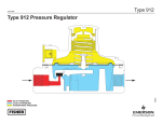
downward and the valve disk moves away from the orifice.
912N Series regulators include an internal relief valve for
overpressure protection.
Overpressure Protection
The 912N Series have outlet pressure ratings lower than their
inlet pressure ratings. Although the internal relief valve provides
very limited downstream overpressure protection, complete
downstream protection is needed if the actual inlet pressure
exceeds the outlet pressure rating.
Overpressuring any portion of these regulators may cause
leakage, damage to regulator parts, or personal injury due to
bursting of pressure-containing parts or explosion of accumulated
gas. Provide appropriate overpressure protection devices to
ensure that none of the limits found in the Specifications section
or Table 1 will be exceeded.
2
Regulator operation with normal operating limits does not
preclude the possibility of damage from external sources or
from debris in the gas line. A regulator should be inspected for
damage after any overpressure condition.
Installation
912N Series regulators may be installed in any position;
however, the spring case vent should be pointed down on
outside installations. If gas escaping through the internal
relief valve could constitute a hazard, the spring case vent
should be piped to a location where escaping gas will not
be hazardous. If the vent will be piped to another location,
obstruction-free tubing should be used and a screened
vent should be installed on the end of the vent pipe. On
all installations, the vent or end of the vent pipe must