1
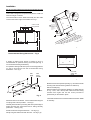
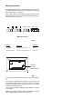
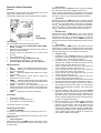
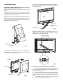
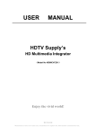
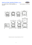
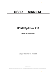
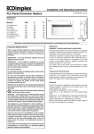
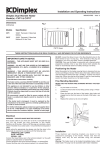
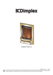
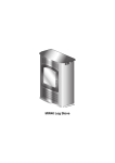
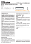
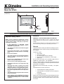
Installation and Operating Instructions 08/18887/1 Wall Fire SP4 Model No: SP420 Issue 1 Dimensions (millimetres) Fig. 1 THESE INSTRUCTIONS SHOULD BE READ CAREFULLY AND RETAINED FOR FUTURE REFERENCE. Important Safety Advice: When using electrical appliances, basic precautions should be followed to reduce the risk of fire, electric shock, and injury to persons, including the following : • If the appliance is damaged, check immediately with the supplier before installation and operation. • This heater must not be used if the front glass is damaged. • Do not use this heater in the immediate surroundings of a bath, shower or swimming pool. • Do not use outdoors. • This heater must not be located immediately above or below a fixed socket outlet or connection box. • Do not cover - Overheating will result if the heater is accidentally covered. • In the event of a fault unplug the heater. • Unplug the heater when not required for long periods. • Although this heater complies with safety standards, we do not recommend its use on deep pile carpets or on long hair type of rugs. • Do not leave young children, the elderly, or the infirm unsupervised in the vicinity of the heater. • The appliance must be positioned so that the plug is accessible. • If the supply cord is damaged it must be replaced by the manufacturer or service agent or similarly qualified person in order to avoid a hazard. Electrical WARNING – THIS APPLIANCE MUST BE EARTHED This heater must be used on an AC ~ supply only and the voltage marked on the heater must correspond to the supply voltage. Do not switch the appliance on until properly installed. Please read all the safety warnings and operating instructions. General Unpack the heater carefully and retain the packaging for possible future use, in the event of moving or returning the fire to your supplier. Contents of Carton. • • • • • SP4 Heater. Wall fixing bracket. Six fixing screws and six wall plugs. Remote control and batteries ( 3 AAA’s type). Spare bulb. Do not connect the heater to an electricity supply until it is installed on a wall correctly. - see ‘Installation’. When in operation there is a 300 watt heat output from the fuel effect, and an additional 120 watt output when the heated glass panel is in operation. The heater can be used remotely or manually. - see ‘Operation’. General features of remote control are: • • • Activate/Deactivate heated glass panel. The illumination of fuel effect can be increased or decreased. Programmable timer. Please note: Used in an environment where background noise is very low, it may be possible to hear the motor which operates the flame effect. This is normal and should not be a cause for concern. Installation Do not connect appliance until properly fixed to the wall and the Instruction leaflet is read fully. a lift appliance above wall fixing bracket This model is designed to be permanently fixed to a wall at a minimum height of 300mm. ledge wall bracket The wall bracket must be fitted horizontally and the cable routed to the bottom right of the heater as in Fig 1. see detail '1' ensure ledge at back of fire engages wall bracket Detail '1' wall bracket outline of wall fixing bracket 480 240 b slide down over bracket, ensure that ledge of appliance engages behind wall bracket and is central d bring level with wall 566 558 c rotate bottom fixing bracket down from its transit position 1158 outline of wall fire 8 600 Fig. 4 Recommended Fixing Dimensions - Fig. 2 A height of 600mm from bottom of heater to floor is recommended for optimum viewing of fuel bed (see Fig. 2 for recommended fixing dimensions). For optimum viewing mark the top four screw fixing positions on wall in accordance with the recommended fixing dimensions - see Fig. 2. wall plugs mark hole centre with pencil wall fixing bracket Fig. 5 Mark the bottom hole position (see Fig. 5), remove the heater ensuring that the bottom fixing bracket is rotated up. Drill and fit wall plug. screws Refit the heater to the wall fixing bracket (i.e. follow steps as in Fig. 4 a,b,c and d above) and rotate the bottom fixing bracket down again and use the screw provided to permanently fix the heater in place. Fig. 3 Drill holes with a 6mm drill bit. Fix the wall bracket using the four plugs and screws provided - see Fig 3. Carefully lift the heater up ensuring that the top rear ledge of heater engages the wall bracket and is sitting centrally positioned. - see Fig 4 (b). Rotate the bottom fixing bracket down. - see Fig 4 (c). Gently bring the heater level with the wall. - see Fig 4 (d). The heater should not be connected until the instruction leaflet is read fully. Manual Operation The Standby Switch (Switch 1) must be first turned ‘ON’ and the AUTO/MAN (Switch 2) switch set to ‘MANUAL’ to operate the manual controls - see Fig 6. Note : When the fire is put in Manual mode the first time the flame effect will come on indicated by the Bottom neon coming on for 3 seconds - see Fig 7. MAN AUTO ON OFF Manual Controls Fig. 6 Setting Operation Indication Flame Effect only Press the ‘ I ’ button (Switch 3) Top Neon Flame Effect & Heat On Press the ‘ I ’ button again (Switch 3) Bottom Neon Neons for indicating operation level Fig. 7 To go to the previous settings press the ‘ O ‘ button (Switch 3). To increase or decrease the brightness of the flames, use the dimmer button (Switch 4). You can have any setting between full brightness and the flames totally off. The heat setting will remain the same. To turn off the power the Standby Switch (Switch 1) must be turned ‘OFF’. Note : Every time that manual mode is selected the previous light and heat settings come on automatically. • Heat settings Navigate the cursor to HEAT with the e f buttons. Press - to change the heat setting between off/low heat. Remote Control Operation General The remote control consists of 5 control buttons and a LCD display with a visible area of 40x40mm. The maximum range of use for the remote control is 15metres. Note: If the room temperature is higher than the remote control set temperature located on the left side of LCD display, heat will not come on (see Thermostat operation below). • Thermostat Navigate the cursor to TEMP with the e f buttons. Press - to set the desired remote control set temperature between 5°C and 35°C and press enter ~. When the room temperature is higher than the remote control set temperature, the heater switches off automatically until the room temperature falls below the remote control set temperature. Fig. 8 LCD Display LCD display The LCD display shows the following functions: • Main menu points: OFF, FLAME, HEAT, TEMP, TIMER, PROG, and TIME. • Brightness of the flame effect shown as a bar chart in 4 steps (50 steps internally). • Remote control set temperature in °C (thermostat function). • • • • Room temperature in °C . Selectable heat settings LOW HEAT / OFF. Time display in format hh:mm – shown as 24hr. Weekdays MON, TUE, WED, THU, FRI, SAT, SUN. • Runback timer Navigate the cursor to TIMER with the e f buttons. Set the hours (0 to 4) with - and press enter ~. Then set the minutes (0 to 59) with - and press enter ~. Now the runback timer is activated (the symbol TIMER appears) and will switch the heater off automatically when the pre-set time is over. • Time setting Navigate the cursor to TIME with the e f buttons. Press the enter button ~ to adjust the weekday with the - buttons. Confirm with the enter button ~ and set the hours and minutes with -. Press enter ~ or f to leave the time menu. • 1. 2. Menu functions 3. • • 4. • • • • • OFF switching off of all functions (stand-by mode). FLAME switching on the flame effect from 0 (off) to 50 (max. brightness). HEAT setting the desired heat position from 0 (off) to 1 (low heat). TEMP preselection of the remote control set temperature from 5°C to 35°C. TIMER selection of the run back timer function (from 1 minute to 4 hours 59 minutes). When the selected time is over the unit will be in stand-by mode. PROG selection of the programming mode. 32 individual programs can be entered. This is a week timer where all functions of the unit can be checked time controlled. TIME setting the time and the weekdays. First steps • • • Fit batteries supplied. Press switch 1 to ON (see Fig. 6). Press switch 2 to AUTO (see Fig. 6) The remote control is now ready. Operating Instructions • Switching ON/OFF The heater can be switched on by pressing the enter ~ or e f buttons. The heater can be switched off by moving the cursor to the OFF menu item. • Flame brightness Navigate the cursor to FLAME with the e f buttons. Press - to change the brightness of the fire effect from off (0) to maximum (50). 5. 6. 7. 8. 9. Program mode Navigate the cursor to PROG with the e f, buttons and press enter . Choose a program number between 1 and 32 with the - buttons and press enter ~. Set the days with - . Single days, Monday until Friday, Saturday and Sunday or Monday until Sunday can be chosen. Press the enter button ~ to accept. Set the program start time with - and confirm the hours and minutes with the enter button ~. Set the program stop time with - and confirm the hours and minutes with the enter button ~. Set the remote control set temperature with - and confirm with the enter button ~. Set the brightness of the fire effect with - from 0 to 50 and confirm with the enter button ~. Set the heat setting between off/low heat/maximum heat with the - button and confirm with the enter button ~. All settings for the first program are done now. Enter a new program according to the steps 1-8 or activate the already entered program by leaving of this menu with the e button. Now the program mode is active, the symbol PROG appears. The heater operates according to the entered information. While the program mode is activated, the start and stop time, the active program number and the remote control set temperature and the room temperature will be displayed alternating. 10. An entered program can be checked, edited and deleted just by navigating again into the PROG menu and pressing the enter button. With the - buttons the different program numbers can be selected. To delete one program number, press the f button. The CP symbol (clear program) appears and by pressing the enter button ~ the current program will be deleted. e f leaves the menu without deleting the program. Replacing the remote control The new remote control must be set up as follows: Press switch 1 to ON . Press switch 2 to AUTO (see Fig. 6). Press switch 3 to O for more than 3 seconds until both LED’s are on (see Fig. 7). Press the remote control’s enter button or the e f buttons. Now the heater has learned the serial number from the remote control and will work with this remote control only (this procedure is repeatable many times). General information 1. In case that the remote control is out of order or the batteries need replacing the fire will stop automatically after 3 minutes. 2. If the batteries are changed the programme memory remains but the time has to be set (see Time setting). Important Battery information. Discard leaky batteries. Dispose of batteries in the proper manner according to Provincial and local regulations. Any battery may leak electrolyte if mixed with a different battery type, if inserted incorrectly, if all the batteries are not replaced at the same time, if disposed of in a fire or if an attempt is made to charge a battery not intended to be recharged. Lamp Replacement WARNING – ALWAYS DISCONNECT FROM THE POWER SUPPLY BEFORE REMOVING LAMPS. For access to the bottom bulbs, carefully slide the flexible rotisserie to one side ensuring that the rubber grommets are not lost (see Fig 11). The front surround will need to be removed in order to change lamps. Warning -The front surround is heavy and easily damaged !. The front surround is fixed with 4 spring loaded pins and is supported at the top by the chassis. To gain access to the lamps please apply the following procedure: While holding the surround by its sides with both hands, carefully pull forwards the surround at the bottom until the pins detach from the clips (see Fig. 9). Grommet Rotate flexible Rotisserie out of position Fig. 11 Remove the defective lamp by unscrewing it (see Fig 12). Replace with a 60W E14 SES clear candle bulb, rotating it. Take care not to over tighten the bulb. Flexible Rotisserie rotated out of position Spring clip Holding Pin Fig. 9 When the bottom holding pins are undone, carefully pull forwards at the top until the top pins detach and then lift the surround up and out (see Fig. 10). Chassis bracket Fig. 12 To refit the surround back to the chassis: Chassis 1. Refit the rotisserie making sure that the rubber grommets are carefully pushed back into the slotted holes on the axial brackets (see Fig 11). Spring clip Holding Pin Fig. 10 2. Place the surround on the chassis bracket and align the pins with the spring slots. Make sure the surround is the correct way up with the cut out for switches at the bottom (see Fig 10). 3. Push firmly at each corner of the surround where the pin is located until it clips back into position. Cleaning WARNING – ALWAYS DISCONNECT FROM THE POWER SUPPLY BEFORE CLEANING THE HEATER. For general cleaning use a soft clean duster – never use abrasive cleaners. The glass viewing screen should be cleaned carefully with a soft cloth. DO NOT use proprietary glass cleaners. After Sales Service Your product is guaranteed for one year from the date of purchase. Within this period, we undertake to repair or exchange this product free of charge (excluding lamps & subject to availability) provided it has been installed and operated in accordance with these instructions. Your rights under this guarantee are additional to your statutory rights, which in turn are not affected by this guarantee. Should you require after sales service you should contact our customer services help desk on 0870 727 0101. It would assist us if you can quote the model number, series, date of purchase, and nature of the fault at the time of your call. The customer services help desk will also be able to advise you should you need to purchase any spares. Please do not return a faulty product to us in the first instance as this may result in loss or damage and delay in providing you with a satisfactory service. Please retain your receipt as proof of purchase. The product complies with the European Safety Standards EN60335-2-30 and the European Standard Electromagnetic Compatibility (EMC) EN55014, EN60555-2 and EN60555-3 which cover the essential requirements of EEC Directives 73/23 and 89/336 Glen Dimplex UK Limited Millbrook House Grange Drive Hedge End Southampton Hampshire. SO30 2DF UK customer help line (8.00AM – 6.00PM Mon-Fri; 8.30AM-1.00PM Sat) Customer Services: Republic of Ireland Tel. Fax. e-mail Tel. 0870 7270101 0870 7270102 [email protected] 01 8424833 [c] Glen Dimplex UK Limited All rights reserved. Material contained in this publication may not be reproduced in whole or in part, without prior permission in writing of Glen Dimplex UK Limited.