1
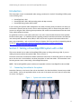
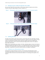
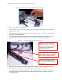
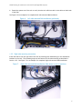
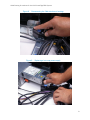
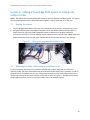
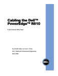
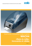
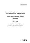
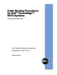
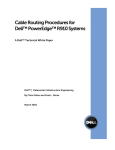
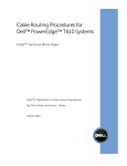
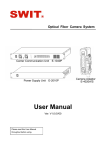
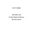
Cable Routing Procedures for the
Dell™ PowerEdge™ R520 System
This Dell Technical White Paper explains the best practices for routing
and securing the cables exiting the back of the R520 system.
Greg Henderson and Jose L. Flores
Data Center Infrastructure Engineering
May 2012
Cable Routing Procedures for the Dell PowerEdge R520 System
This document is for informational purposes only and may contain typographical errors and
technical inaccuracies. The content is provided as is, without express or implied warranties of any
kind.
© 2012 Dell Inc. All rights reserved. Dell and its affiliates cannot be responsible for errors or omissions
in typography or photography. Dell, the Dell logo, and PowerEdge are trademarks of Dell Inc. Other
trademarks and trade names may be used in this document to refer to either the entities claiming the
marks and names or their products. Dell disclaims proprietary interest in the marks and names of
others.
May 2012| Rev 1.0
2
Cable Routing Procedures for the Dell PowerEdge R520 System
Contents
Introduction ............................................................................................................. 4
Section 1: Cabling a PowerEdge R520 system with a CMA....................................................... 4
1.1.
Connecting the cables to the system ................................................................... 4
1.2.
Routing the power cables through the strain reliefs ................................................. 5
1.3.
Installing the CMA .......................................................................................... 5
Section 2: Replacing a hot swap power supply on a PowerEdge R520 system with a CMA ............... 8
2.1.
Replacing a hot swap power supply with a left-side mounted CMA ............................... 8
2.2.
Replacing a hot swap power supply with a right-side mounted CMA ............................. 8
Section 3: Cabling a PowerEdge R520 system on sliding rails without a CMA ............................. 10
3.1.
Routing the cables ....................................................................................... 10
3.2.
Removing the outer CMA brackets for shallow racks .............................................. 10
Section 4: Cabling a PowerEdge R520 system installed on static rails ..................................... 11
Figures
Figure 1.
System with cables installed ............................................................................. 4
Figure 2.
Routing power cables through the strain reliefs on hot swap power supplies .................. 5
Figure 3.
Routing the power cable through the strain relief on a fixed power supply .................... 5
Figure 4.
Attaching the inner CMA attachment bracket ........................................................ 6
Figure 5.
Routing the cables through the CMA .................................................................... 6
Figure 6.
Left-side mounted CMA installation (preferred) ...................................................... 7
Figure 7.
Right-side mounted CMA installation (CMA shown in service position) ........................... 7
Figure 8.
Disconnecting the CMA attachment housings ......................................................... 9
Figure 9.
Replacing a hot swap power supply ..................................................................... 9
Figure 10. Cable routing on sliding rails without a CMA ........................................................ 10
Figure 11. Removing the outer CMA brackets for shallow racks .............................................. 11
Figure 12. Cabling a system installed in static rails ............................................................. 11
3
Cable Routing Procedures for the Dell PowerEdge R520 System
Introduction
This white paper covers recommended cable routing procedures for the Dell™ PowerEdge™ R520 system
in the following racks:
•
•
•
PowerEdge 2410, 4210
PowerEdge 2420, 4220, 4820 (including wide and deep versions)
PowerEdge Energy Smart 4020S, 4620S
If you are using the optional cable management arm (CMA), following these procedures will allow you
to extend the system from the rack for service without powering down or disconnecting the cables. If
you are not using the CMA, following these procedures will ensure secure attachment and strain relief
of the cables behind the system.
For guidelines on how to route cables within the rack, refer to the Dell Best Practices Guide for Rack
Enclosure white paper. For additional details regarding potential interferences between the CMA and
rear-mount power distribution units (PDUs) in Dell racks as well as general information about third
party rack compatibility, refer to the Dell Enterprise Systems Rail Sizing and Rack Compatibility Matrix
located at http://content.dell.com/us/en/enterprise/d/business~solutions~engineeringdocs~en/Documents~rail-rack-matrix.pdf.aspx.
Section 1: Cabling a PowerEdge R520 system with a CMA
This section details how to cable the PowerEdge R520 system on sliding rails using a CMA. If you are
cabling the system without the optional CMA, refer to Section 3.
Follow the instructions contained in the Rack Installation Instructions in the sliding rail kit to install the
server into the rack. Once installed, use these instructions to install the cables. All illustrations in the
following sections were created using a PowerEdge R520 system.
NOTE: The PowerEdge R520 system is backward compatible with the PowerEdge R510 rails and CMA.
1.1. Connecting the cables to the system
Attach the CMA tray to the back of the rails as described in the CMA Installation Instructions provided
in the CMA kit. Connect all applicable cables to the rear of the system and verify that all connections
are secure. See Figure 1.
Figure 1.
System with cables installed
4
Cable Routing Procedures for the Dell PowerEdge R520 System
1.2. Routing the power cables through the strain reliefs
After you have installed the tray and cables, route the power cable(s) through the strain relief(s)
located on the power supply handle(s) as shown in Figures 2 & 3.
Figure 2.
Figure 3.
Routing power cables through the strain reliefs on hot swap power supplies
Routing the power cable through the strain relief on a fixed power supply
1.3. Installing the CMA
The CMA can be installed on either the rear right or rear left side of the rails as described in the CMA
Installation Instructions. Mounting the CMA on the side that is opposite of the power supplies (left-side
mount) is recommended for systems with hot swap power supplies; otherwise, the CMA must be
partially disconnected in order to remove the outer power supply. Refer to Section 2 for details on
power supply replacement.
NOTE: If you are installing fiber-optic cables in the CMA, a cable bend radius of at least 1 inch must be
maintained throughout the length of the cable. It is recommended that fiber-optic cables be routed on
the exterior of the cable bundle to increase the bend radius of the fiber-optic cables through the CMA.
Additionally, a large amount of slack at the entrance and exit of the CMA is recommended.
1.3.1. Installing the inner CMA attachment bracket
As described in the CMA Installation Instructions, locate and attach the appropriate inner CMA
attachment bracket based on which side you wish to mount the CMA. Use the bracket marked “A” for
mounting the CMA on the left side, and the bracket marked “B” for mounting on the right side. See
Figure 4.
5
Cable Routing Procedures for the Dell PowerEdge R520 System
Figure 4.
Attaching the inner CMA attachment bracket
1.3.2. Left-side mounting instructions
1. Install the CMA on the rear left side of the rails by attaching both CMA housings to the attachment
brackets on the rails.
2. Route the cables through the CMA while avoiding twisting the cables. Use the hook-and-loop straps
on the CMA to secure the cables.
3. If the cable bundle includes a keyboard, video, and mouse system interface pod (KVM SIP), it can
be placed inside the CMA basket when the CMA is mounted on the left side. See Figure 5.
Figure 5.
Routing the cables through the CMA
NOTE: Do not store excess cable
slack inside the CMA. The cables
may protrude through the CMA, thus
causing binding and potentially
damaging the cables.
Cables entering the CMA should have a
small amount of slack to avoid cable
strain when the CMA is extended.
KVM SIP can be placed inside the
basket when the CMA is mounted on
the left side.
4. Once you have routed all of the cables through the CMA, dress the cable slack between the back of
the system and the entrance of the CMA using the tie wraps provided in the CMA kit.
5. Clip off the excess length of material from the tie wraps. Make sure that the heads of the tie wraps
are positioned so as to avoid interference with adjacent systems. Return the CMA to the closed
(retracted) position.
6
Cable Routing Procedures for the Dell PowerEdge R520 System
6. Extend the system out of the rack to verify that there is sufficient slack in the cables on both ends
of the CMA.
See Figure 6 for an example of a completed left-side mounted CMA installation.
Figure 6.
Left-side mounted CMA installation (preferred)
1.3.3. Right-side mounting instructions
Install the CMA on the rear right side of the rails by attaching both CMA housings to the attachment
brackets on the rails. The remaining steps are the same as for left-side mounting as described in
Section 1.3.2. See Figure 7 for an example of a completed right-side mounted CMA installation.
Figure 7.
Right-side mounted CMA installation (CMA shown in service position)
7
Cable Routing Procedures for the Dell PowerEdge R520 System
Section 2: Replacing a hot swap power supply on a PowerEdge
R520 system with a CMA
2.1. Replacing a hot swap power supply with a left-side mounted CMA
1. Swing the CMA to its service position as described in the CMA Installation Instructions provided
with the CMA kit.
2. If the bottom power supply is being replaced, first remove the tray from underneath the CMA as
described in the CMA Installation Instructions. If the top power supply is being replaced, the tray
can remain in place.
3. Disengage the strain relief and disconnect the power cord from the power supply.
4. Replace the power supply.
5. Plug in the power cord, re-engage the strain relief, replace the CMA support tray (if necessary),
and return the CMA to the closed (retracted) position.
2.2. Replacing a hot swap power supply with a right-side mounted CMA
1. Swing the CMA to its service position as described in the CMA Installation Instructions provided
with the CMA kit.
2. If the bottom power supply is being replaced, first remove the tray from underneath the CMA as
described in the CMA Installation Instructions. If the top power supply is being replaced, the tray
can remain in place.
3. Disengage the strain relief and disconnect the power cord from the power supply.
4. Disconnect both CMA attachment housings from the brackets on the rails as shown in Figure 8.
5. Detach the inner CMA bracket from the rail by pushing on the end of the lock spring and lifting the
bracket up and to the left until it clears the standoffs on the rail.
6. While supporting the CMA with one hand, remove and replace the power supply with the other
hand as shown in Figure 9.
7. Reinstall the inner CMA bracket to the rail and reconnect the CMA to the brackets.
8. Plug in the power cord, re-engage the strain relief, replace the CMA support tray (if necessary),
and return the CMA to the closed (retracted) position.
8
Cable Routing Procedures for the Dell PowerEdge R520 System
Figure 8.
Disconnecting the CMA attachment housings
Figure 9.
Replacing a hot swap power supply
9
Cable Routing Procedures for the Dell PowerEdge R520 System
Section 3: Cabling a PowerEdge R520 system on sliding rails
without a CMA
NOTE: The CMA for the Dell PowerEdge R520 system is optional. Without the CMA installed, the system
must be powered down and all cables disconnected before it can be extended out of the rack.
3.1. Routing the cables
1. Connect all applicable cables to the rear of the system and verify that all connections are secure.
2. Using the hook-and-loop straps supplied with the rail kit, bundle the cables and secure them to
either the left or right outer CMA attachment bracket as described in the Rack Installation
Instructions. See Figure 10 for an example of data cables secured to the left outer CMA bracket and
power cables secured to the right outer CMA bracket (as viewed from the rear of the system).
Figure 10.
Cable routing on sliding rails without a CMA
3.2. Removing the outer CMA brackets for shallow racks
If you are installing the system into a shallow rack (less than 1 meter deep) and you will not be
installing a CMA, the outer CMA brackets may be removed from the sliding rails if necessary in order to
allow the rails to fit properly into the rack. Remove the brackets by using a #2 Phillips screwdriver to
remove the screws that secure the brackets to the rails as shown in Figure 11. Use the hook-and-loop
straps supplied with the rail kit to secure the cables to the rack frame if desired.
10
Cable Routing Procedures for the Dell PowerEdge R520 System
Figure 11.
Removing the outer CMA brackets for shallow racks
Section 4: Cabling a PowerEdge R520 system installed on static
rails
NOTE: The CMA is compatible only with the sliding rails, not the static rails.
1. Follow the instructions contained in the Rack Installation Instructions found in the static rail kit to
install the server into a two-post or four-post rack.
2. Install the hook-and-loop straps provided in the rail kit through the slots in the rear brackets of the
rails as described in the Rack Installation Instructions.
3. Connect all applicable cables to the rear of the system and verify that all connections are secure.
4. Using the hook-and-loop straps, bundle the cables and secure them to either the left rail or right
rail as described in the Rack Installation Instructions. See Figure 12 for an example of data cables
secured to the left rail and power cables secured to the right rail (as viewed from the rear of the
system).
Figure 12.
Cabling a system installed in static rails
11