1
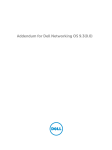
Dell Networking Installation Guide for the
Z9500 Switch
Notes, Cautions, and Warnings
NOTE: A NOTE indicates important information that helps you make better use of your computer.
CAUTION: A CAUTION indicates either potential damage to hardware or loss of data and tells you
how to avoid the problem.
WARNING: A WARNING indicates a potential for property damage, personal injury, or death.
Copyright © 2014 Dell Inc. All rights reserved. This product is protected by U.S. and international copyright and
intellectual property laws. Dell™ and the Dell logo are trademarks of Dell Inc. in the United States and/or other
jurisdictions. All other marks and names mentioned herein may be trademarks of their respective companies.
2014–07
Rev. A02
Contents
1 About this Guide....................................................................................................5
Related Publications.............................................................................................................................. 5
2 Introduction...........................................................................................................6
Product Description.............................................................................................................................. 6
3 Unpacking the Switch.......................................................................................... 7
Hardware Installation Overview............................................................................................................ 7
4 Hardware Overview..............................................................................................9
I/O Panel................................................................................................................................................ 9
Utility Panel.......................................................................................................................................... 10
Power Supplies.............................................................................................................................. 10
Fans................................................................................................................................................ 10
System Status.......................................................................................................................................10
5 Site Preparation...................................................................................................14
Site Selection....................................................................................................................................... 14
Cabinet Placement.............................................................................................................................. 14
Storing Components........................................................................................................................... 15
6 Z9500 Installation...............................................................................................16
Assemble 4–Post Rack Frame............................................................................................................ 16
Attaching the Mounting Brackets....................................................................................................... 16
Attaching the Static-Rails Mounting Brackets.............................................................................. 16
Installing the Dell Static Rails System..................................................................................................17
Identifying the Rail Kit ContentsInstalling and Removing Tool-less Rails (SquareHole)Installing and Removing Tooled Rails (Threaded-Hole Racks or Round-Hole Racks)...... 17
Mounting the Chassis in a Four-Post Rack........................................................................................20
Securing the Chassis Ground............................................................................................................. 24
Installing Fan Modules.........................................................................................................................25
Installing AC Power Supplies.............................................................................................................. 26
Securing Power Cables.......................................................................................................................28
Installing the Cable Management System (OPTIONAL).................................................................... 29
Installing the Cable Management System for Direct Attach Copper (DAC) Cables................... 29
Installing the Cable Management System for Optical Fibres.......................................................31
Installing the QSFP+ Optics................................................................................................................32
Port Numbering Convention.............................................................................................................. 33
Splitting QSFP+ Ports to SFP+ Ports.................................................................................................. 33
Important Points to Remember....................................................................................................34
Supplying Power and Powering Up the System................................................................................ 34
AC Power.......................................................................................................................................34
7 Technical Specifications....................................................................................35
8 Agency Compliance........................................................................................... 36
USA Federal Communications Commission (FCC) Statement......................................................... 36
Canadian Department of Communication Statement...................................................................... 36
European Union EMC Directive Conformance Statement............................................................... 36
European Community Contact.....................................................................................................37
Japan: VCCI Compliance for Class A Equipment.............................................................................. 37
Korean Certification of Compliance.................................................................................................. 38
Safety Standards and Compliance Agency Certifications................................................................. 38
Electromagnetic Compatibility (EMC)................................................................................................38
Product Recycling and Disposal.........................................................................................................39
9 Technical Support.............................................................................................. 40
The iSupport Website......................................................................................................................... 40
Accessing iSupport Services...............................................................................................................40
Requesting a Hardware Replacement............................................................................................... 40
Contacting Technical Support............................................................................................................41
About this Guide
1
This guide provides site preparation recommendations, and step-by-step procedures for rack mounting,
installing modules, and connecting to a power source.
After you have completed the hardware installation and power-up of the Z9500, for software
configuration information, refer to the Dell Networking Configuration Guide for the Z9500 Switch and for
Command Line Interface (CLI) information, refer to the Dell Networking Command Line Reference Guide
for the Z9500 Switch.
CAUTION: To avoid electrostatic discharge (ESD) damage, wear grounding wrist straps when
handling this equipment.
WARNING: Only trained and qualified personnel can install this equipment. Read this guide
before you install and power up this equipment. This equipment contains two power cords.
Disconnect both power cords before servicing.
WARNING: This equipment contains optical transceivers, which comply with the limits of Class 1
laser radiation.
WARNING: When no cable is connected, visible and invisible laser radiation may be emitted from
the aperture of the optical transceiver ports. Avoid exposure to laser radiation and do not stare
into open apertures.
Related Publications
For more information about the Z9500, refer to the following documents:
•
Dell Networking Configuration Guide for the Z9500 Switch
•
Dell Networking Command Line Reference Guide for the Z9500 Switch
•
Dell Networking Release Notes for the Z9500 Switch
NOTE: For the most recent documentation and software, visit iSupport (registration for access to
some sections is required): http://www.dell.com/support/manuals.
About this Guide
5
2
Introduction
This document provides basic information about installing the Z9500 switch.
For information about how to configure and monitor switch features, refer to the Dell Networking
Configuration Guide for the Z9500 Switch, which is available on the Dell Support website at http://
support.dell.com/manuals.
This document contains the following sections:
•
Product Description
•
Unpacking the Switch
•
Hardware Overview
•
Site Preparations
•
Z9500 Installation
•
Technical Specifications
•
Agency Compliance
•
Technical Support
Product Description
The Z9500 is part of Dell Networking's Z-Series family of Data Center Core switches.
The Z9500 switch is a compact 3 RU (Rack Unit), high-performance, and low-latency 10/40–Gigabit
Ethernet switch. It runs the Dell Networking Operating Software (OS) , providing features and capabilities
that are widely deployed.
The Z9500 switch has the following features:
•
132 fixed Quad Small Form-Factor Pluggable (QSFP+) ports on the I/O side of the switch.
•
Four slots on the Utility side of the switch for hot swappable power supplies.
•
Five slots on the Utility side of the switch for hot swappable fan modules.
•
A management and console interface on the I/O side of the switch.
6
Introduction
Unpacking the Switch
3
The switch and its accessories are shipped in a single box. The power cords may be shipped in a separate
box. Before unpacking the switch, inspect the container and immediately report any evidence of damage.
Verify that you have received your ordered items, including the following:
WARNING: If any item is missing or damaged, contact your Dell Networking representative or
reseller for instructions.
CAUTION: Always wear an ESD-preventive wrist or heel ground strap when handling the switch
and its components. Ground yourself by using an antistatic wrist strap or other device and
connect it to the ESD grounding jack on the chassis. As with all electrical devices of this type, take
all necessary safety precautions to prevent injury when installing this system.
CAUTION: The system is packaged in one or two separate containers. Use an equipment lift or
pallet jack to lift or install the chassis. Lifting the system by its shelves will cause damage to the
chassis
•
Z9500 switch
•
Static-Rail kit (#1 and #2 Phillips and flat-tipped screwdrivers required)
NOTE: One Rail Kit is required for every chassis in a rack.
•
Screws for rack installation
•
Console cables
•
Any optional items ordered
•
Getting Started Guide
•
Safety and Regulatory Information
•
Warranty and Support Information
•
Software License Agreement
1.
Place the container on a clean, flat surface and cut all straps securing the container.
2.
Open the container or remove the container top.
3.
Carefully remove all components from the container and place it on a secure and clean surface.
4.
Remove all packing material.
5.
Inspect the switch and accessories for damage.
Hardware Installation Overview
To install the Z9500, follow these steps:
1.
Assemble 4-Post Rack Frame
2.
Attaching the Mounting Brackets
3.
Installing the Dell Static Rails System
4.
Securing the Chassis Ground
5.
Installing AC Power Supplies
Unpacking the Switch
7
6.
Installing Fan Modules
7.
Securing Power Cables
8.
Installing the QSFP+ Optics
9.
Installing the Cable Management System
10. Supplying Power and Powering Up the System
8
Unpacking the Switch
Hardware Overview
4
This section contains information about device characteristics and modular hardware configurations for
the Z9500. The Z9500 has the following physical dimensions:
•
Height: 5.2 inches (132.08 mm)
•
Width: 17.4 inches (441.96 mm)
•
Depth: 32 inches (812.80 mm)
The Z9500 has a chassis design with 5280Gbps switching bandwidth. The system also provides one DB9
RS-232 console port with YOST RJ-45 pinout and a dedicated Ethernet service port for out-of-band
(OOB) management functions.
I/O Panel
All fixed data ports (132 × 40GbE quad small form-factor pluggable plus [QSFP+] ports) are on the I/O
panel.
Figure 1. I/O Panel
The I/O panel includes:
•
132 fixed Quad Small Form-Factor Pluggable (QSFP+) ports
•
Light Emitting Diodes (LEDs)
•
Management ports
NOTE: The LED displays for the system status are on the I/O side of the chassis. The fan and power
status LEDs are on the Utility panel.
Hardware Overview
9
Utility Panel
The Utility panel side of the platform contains the fan and power modules.
Figure 2. Utility Side
1.
Fan Trays
2.
Power Supplies
Power Supplies
The Z9500 supports four hot-swappable Power supply units (PSUs) .
NOTE: The PSUs must be installed at the customer site.
PSUs are field replaceable. To ensure power redundancy and adequate cooling, install four power
supplies in the switch. When running with full redundancy (four PSUs installed and running), you can
remove and replace a PSU while the other PSUs are running without disrupting traffic.
Fans
The Z9500 supports five fan trays with airflow directions from I/O to Utility.
The fans must be installed at the customer site.
System Status
You can view Z9500 status information in several ways, including:
•
LEDs
•
CLI show commands
•
Simple network management protocol (SNMP)
For more information about these options, refer to the Dell Networking Command Line Reference Guide
and Dell Networking Configuration Guide for the Z9500 Switch.
As shown in the following figure, the Z9500 includes LED displays on the I/O and Utility side of the
chassis. When the Z9500 powers up or reloads, the status LED on the power supplies are solid green.
10
Hardware Overview
The following table lists the LED definitions for the Z9500 system.
Figure 3. System LED Displays (I/O Panel)
1.
Alarm LED
2.
System status LED
3.
System locator LED
4.
10GbE channel selection indicator
5.
10GbE channel selector button
6.
Management Port Activity LED
7.
Management Port Status LED
Table 1. System LED Displays (I/O Panel)
Label
LED Color/
Display
Description
Alarm LED
•
•
•
Off
Amber solid
Red solid
•
•
•
No alarm
Minor alarm
Major alarm
System status LED
•
•
•
Off
Green solid
Green
blinking
•
•
•
No power
Normal operation
System is booting
System locator LED
•
•
Off
Blue solid
•
•
No activity
Port locator
•
•
Off
Green
blinking
•
•
No activity
The port and the link are active, and there is
link activity
Management port activity LED
Hardware Overview
11
Label
LED Color/
Display
Description
Management port status LED
•
•
•
•
Off
Green solid
Port is Down
Traffic on Management Port
Figure 4. 40GbE Port LEDs (I/O Panel)
1.
Port LED
NOTE: In 40GbE mode, the front end ports are “solid green” color in operational state. However, if
the port is configured to work in 10GbE mode, then the front end ports are “solid amber” color in
operational state.
NOTE: The four 10GbE ports split from a single 40GbE port share the same locator LED as the
40GbE port. Use the CLI system location-led interface fortyGigE /tengigabitethernet SLOT/PORT on
command to locate the 10GbE/40GbE port and then press the channel selector button to locate
the corresponding 10GbE port as shown in Figure 3. When port locator functionality is enabled on a
port - the corresponding port LED turns solid blue.
Table 2. 40GbE Port LEDs
Label
LED Color/Display
Description
Port locator LED
•
•
Off
Blue
•
•
No activity
Port locator
Port link/activity LED
•
•
•
•
•
Off
Green solid
Green blinking
Amber solid
Amber blinking
•
•
•
•
•
No link or interface disabled
40GbE link present and interface enabled
Port has activity
10GbE link present and interface enabled
10GbE port has activity
12
Hardware Overview
Figure 5. System LED Displays (Utility Panel)
1.
Fan status LED
2.
PSU status LED
Table 3. System LED Displays (Utility Panel)
Label
LED Color/Display
Description
PSU status LED
•
•
•
Green solid
Amber Solid
Off
•
•
•
Normal operation
Minor/Major alarms
Power not present
Fan status LED
•
•
•
Green solid
Amber Solid
Off
•
•
•
Normal operation
Minor/Major alarms
Power not present
Hardware Overview
13
5
Site Preparation
The Z9500 is suitable for installation as part of a Common Bond Network (CBN). It can be installed in:
•
network telecommunication facilities
•
data centers
•
other locations where the National Electric Code (NEC) applies
This chapter contains the following sections:
•
Site Selection
•
Cabinet Placement
•
Storing Components
Site Selection
Dell Networking equipment is intended for installation in restricted access areas. A restricted access area
can only be accessed by service personnel by using a special tool, lock, key or other means of security
and access is controlled by the authority responsible for the location.
Ensure that the area where you install your Z9500 system meets the following safety requirements:
•
Near an adequate power source. Connect the system to the appropriate branch circuit protection as
defined by your local electrical codes.
•
Environmental temperature between 32° to 104°F (0° to 40°C).
•
Humidity that does not exceed 85 percent noncondensing.
•
In a dry, clean, well-ventilated and temperature-controlled room, away from heat sources such as hot
air vents or direct sunlight.
•
Away from sources of severe electromagnetic noise.
•
Positioned in a rack or cabinet, or on a desktop with adequate space in the front, rear, and sides of the
Z9500 for proper ventilation and access.
Cabinet Placement
Install the Z9500 only in indoor cabinets designed for use in a controlled environment as described in Site
Selection.
The cabinet must meet the following criteria:
•
14
Minimum cabinet size and airflow are according to the Electronic Industries Alliance (EIA) standard.
Site Preparation
Storing Components
If you do not install your Z9500 and components immediately, Dell Networking recommends properly
storing the system and all optional components until you are ready to install them.
WARNING: ESD damage can occur when components are mishandled. Always wear an ESDpreventive wrist or heel ground strap when handling the Z9500 and its accessories. After you
remove the original packaging, place the Z9500 and its components on an anti-static surface.
1.
Storage temperature must remain constant ranging from -4° to 158° F (-20°C to 70° C).
2.
Store on a dry surface or floor, away from direct sunlight, heat, and air conditioning ducts.
3.
Store in a dust-free environment.
Site Preparation
15
6
Z9500 Installation
To install the Z9500, follow these steps:
1.
Assemble 4-Post Rack Frame
2.
Attaching the Mounting Brackets
3.
Installing the Dell Static Rails System
4.
Securing the Chassis Ground
5.
Installing Fan Modules
6.
Installing AC Power Supplies
7.
Securing Power Cables
8.
Installing the Cable Management System
9.
Installing the QSFP+ Optics
10. Supplying Power and Powering Up the System
Assemble 4–Post Rack Frame
Due to chassis weight, the Z9500 switch does not support installation in a 2-post rack; you must install
the Z9500 in a 4-post rack. To install a 4-post rack frame, follow the instructions in your rack frame kit.
In a 4-post rack, the maximum supported distance between the front and back vertical posts is 36 inches;
the minimum supported distance is 24 inches.
Attaching the Mounting Brackets
The switch is shipped with static rails mounting brackets (rack ears) and the required screws for rack or
cabinet installation. The brackets are enclosed in a package with the chassis.
Attaching the Static-Rails Mounting Brackets
1.
Take the static-rail mounting brackets and screws out of their packaging.
2.
Attach the brackets to the I/O side of the chassis, using eight screws for each bracket.
Attach each bracket so that the “ear” faces the I/O side with the black thumb screw at the bottom of
the “ear” (as shown in the following illustration).
16
Z9500 Installation
1.
Utility side of the chassis
3.
Static-rail mounting bracket
2.
Screws
Installing the Dell Static Rails System
Dell Networking provides the Static Rails rack mounting system so you can easily configure a rack to
install the switch.
Identifying the Rail Kit Contents
Locate the components for installing the rail kit assembly:
•
Two Dell Static Rails assemblies (1) (2).
NOTE: Supports rack length between 24 and 36 inches.
Z9500 Installation
17
Installing and Removing Tool-less Rails (Square-Hole)
1.
Position the left and right rail end pieces FRONT facing inward and orient each end piece to seat in
the holes on the front side of the vertical rack flanges (1).
2.
Align each end piece in the bottom and top holes of the desired U spaces (2).
3.
Engage the back end of the rail until it fully seats on the vertical rack flange and the latch clicks into
place. Repeat these steps to position and seat the front end piece on the vertical flange.
NOTE: Make sure the blue release latch is closed.
4.
18
To remove the rails, pull on the blue release latch on each end piece and unseat the rail from the
rack.
Z9500 Installation
Installing and Removing Tooled Rails (Threaded-Hole Racks or Round-Hole
Racks)
1.
Remove the pins from the front and rear mounting brackets using a flat-tipped screwdriver (2).
2.
Pull on the rail latch subassemblies to remove them from the mounting brackets (1).
3.
Attach the left and right mounting rails to the front vertical rack flanges using two pairs of screws.
4.
Slide the left and right rear brackets forward against the rear vertical rack flanges and attach them
using two pairs of screws (3).
Z9500 Installation
19
Mounting the Chassis in a Four-Post Rack
Safety Considerations for Rack Mounting
WARNING: You must use a lifting device, such as a fork-lift trolley, to lift the chassis.
The following guidelines are general safety considerations. For detailed information, read the safety
instructions in your Safety, Environmental, and Regulatory information booklet before you begin.
•
•
20
Rack loading — Overloading or uneven loading of racks may result in shelf or rack failure, which may
damage equipment and cause possible personal injury. Stabilize racks in a permanent location before
loading begins. Mount the components beginning at the bottom of the rack, then work to the top. Do
not exceed your rack load rating.
Power considerations — Connect only to the power source specified on the unit. When multiple
electrical components are installed in a rack, ensure that the total component power ratings do not
exceed the circuit capabilities. Overloaded power sources and extension cords present fire and shock
hazards.
Z9500 Installation
•
•
•
•
•
Elevated ambient temperature — If installed in a closed rack assembly, the operating temperature of
the rack environment may be greater than the room ambient temperature. Use care not to exceed the
40°C maximum ambient temperature of the switch.
Reduced air flow — Install the equipment in the rack so that the amount of airflow required for safe
operation of the equipment is not compromised.
Reverse air flow — Necessary clearance is required to ensure cool air intake and to avoid hot air blow
out from I/O panel.
Reliable earthing — Maintain reliable earthing of rack-mounted equipment. Pay particular attention to
the supply connections other than the direct connections to the branch circuit; for example, use of
power strips.
Do not mount the equipment with the Utility panel facing in the downward position.
NOTE: The illustrations in this document are not intended to represent a specific switch.
Installing the Switch in a 1200 mm Rack Enclosure
To install the Z9500 in a rack enclosure which must have front and back doors closed and provide
enough space for cables (I/O and power supply), you must use an extended rack that is at least 1200 mm
in depth.
To install the Z9500 in a 1200 mm rack enclosure:
1.
Re-position and fasten the front rack posts (vertical rails) 6 inches back towards the rear of the rack.
2.
Verify that the position of the rear vertical rails within the rack line up for the mount distance (from
the front vertical rails) as you snap the mounting rails into place. If the rear vertical rails require
adjustment, adjust as necessary.
3.
Lift the chassis, align it with the rails installed in the rack, and slide the chassis into the rack. The front
I/O panel of the chassis should be flush with the front vertical rails and sit 6 inches back from the
front door. There should be sufficient space to attach QSFP+ optics and cables to the front I/O
panel. There should also be adequate room to attach power supply cables at the rear of the chassis.
4.
Tighten the screws on each side of the front panel.
Installing the Switch in a 1070 mm Rack Enclosure
This section describes your options to install the Z9500 switch in a 1070 mm rack enclosure. Due to
chassis depth, the Z9500 switch does not support installation in a 1070 mm cabinet with front and back
doors closed. If your Z9500 installation requires both front and back doors to be closed, use a rack
enclosure with extended length.
When you install the Z9500 switch in a 1070 mm rack enclosure with a front and back door, you must
either leave the front door open or remove it. (This is the typical Z9500 installation scenario. If you must
close the front door, refer to procedure for installing the switch in a rack enclosure with no back door
later in this section.)
To install the Z9500 in a 1070 mm rack enclosure with no front door:
1.
Lift the chassis, align it with the rails installed in the rack, and slide the chassis into the rack. The front
I/O panel of the chassis should be flush with the rack opening and provide adequate space on the
PSU side of the chassis to attach power cords (see the following figure).
2.
Tighten the screws on each side of the front panel.
To remove the chassis from the rack, loosen the screws and slide the chassis out of the rack.
Z9500 Installation
21
Installing the Z9500 in a Rack Enclosure with No Front Door
1.
Top view of rack enclosure (for example, Dell
4226 – 1070 mm cabinet)
2.
Front door has been removed.
When you install the Z9500 switch in a 1070 mm rack enclosure in which the front door must be closed,
either leave the back door open or remove the back door. Then follow these steps.
1.
Re-position and fasten the front rack posts (vertical rails) 6 inches back towards the rear of the rack
(as shown in the next figure).
2.
Lift the chassis, align it with the rails installed in the rack, and slide the chassis into the rack. The front
I/O panel of the chassis should be flush with the front vertical rails and sit 6 inches back from the
front door. There should be sufficient space to attach QSFP+ optics and cables to the front I/O
panel.
22
Z9500 Installation
3.
Tighten the screws on each side of the front panel.
NOTE: If your 1070 mm rack enclosure uses vertical power distribution units (PDUs) that occupy the
space required by the Z9500 when it is installed 6 inches from the front door, do one of the
following:
•
Replace the vertical PDUs with shorter or horizontal PDUs.
•
Use an extended-length (1200 mm) rack.
Installing the Z9500 in a Rack Enclosure with No Back Door
1.
Top view of rack enclosure (for example, Dell
4226 – 1070 mm cabinet)
2.
Adjustable front vertical rails
3.
6 inches behind front door
4.
Back door has been removed.
Z9500 Installation
23
1.
Additional screw to restrict front-back
movement of the switch
2.
Main screw
Securing the Chassis Ground
After you mount the chassis, secure the chassis ground as follows:
1.
24
Locate the chassis ground connector nuts on the chassis rear.
Z9500 Installation
2.
Install the grounding cables to the ground nuts. The grounding cable must comply with your local
electrical codes in size and color (typically the color is green or green with yellow stripe).
NOTE: For proper ventilation, position the chassis in an equipment rack (or cabinet) with a
minimum of 5 inches (12.7 cm) of clearance around exhaust vents. The acceptable ambient
temperature ranges are listed in the Environmental Parameters section.
Use M5 screws.
3.
Tighten the screws (torque should be between 18 and 24 inch/lbs).
4.
Connect the opposite end of the grounding cable to the nearest appropriate facility grounding post.
Figure 6. Cable Connector
Installing Fan Modules
The chassis requires five fan modules to be installed for normal configuration. The airflow direction must
be from I/O to Utility.
Important Points to Remember for Installing a Fan Module
•
The Utility panel consists of five slots numbered from 0 to 4. Insert the fan modules in slots 0, 1, 2, 3,
and 4. Module slot 0 is on the left side of the chassis; module slot 4 is on the right side of the chassis.
•
Fan modules are hot-swappable. If you remove a fan module during normal Z9500 operation, you
must insert a new fan module within three minutes.
•
If a fan module fails, the system during normal operation continues to operate without a significant
degradation in cooling capacity for a TBD duration.
Z9500 Installation
25
•
The cooling system is designed such that, during normal operation, the fans typically run at
somewhere between 40 and 50 percent of their maximum speed at 26°C ambient temperature. This
feature results in lower noise and higher average fan life. The switch increases the fan speed to
maximum if the facility air condition fails or if a fan fails.
•
The fan speed increases and decreases automatically based on the internal temperature. The switch
never intentionally turns off the fans.
•
For proper ventilation, position the switch in an equipment rack (or cabinet) with a minimum of 5
inches (12.7 cm) of clearance around the exhaust vents. When you install two systems near each
other, position the two chassis at least 5 inches (12.7 cm) apart to permit proper airflow. The
acceptable ambient temperature ranges are listed in Technical Specifications.
•
To view the log messages, use the show logging command. For more information, refer to the
System Logs chapters of the Dell Networking OS Command Line Reference Guide for the Z9500
Switch and Dell Networking OS Configuration Guide for the Z9500 Switch.
1.
Take the fan module out of the shipping box.
2.
Use the grab handle to slide the fan module into the switch fan slot, as shown below.
Figure 7. Installing a Fan Module
1.
Release latch
2.
Fan module 0/Slot 0
Installing AC Power Supplies
The chassis requires four power supplies to be installed for normal configuration. The airflow direction
must be from I/O to Utility.
Important Points to Remember for Installing an AC Power Supply
•
The power supply unit (PSU) slides into the slot smoothly. Do not force a PSU into a slot as this action
may damage the PSU or the chassis.
•
The chassis supports AC power supplies with air-flow direction from I/O to Utility.
26
Z9500 Installation
•
For PSUs, a LED indicates the power status.
•
To view the log messages, use the show logging command. For more information, refer to the
System Logs chapters of the Dell Networking OS Command Line Reference Guide for the Z9500
Switch and Dell Networking OS Configuration Guide for the Z9500 Switch.
WARNING: Although the switch can run on two PSUs, Dell Networking requires using four PSUs
for full redundancy and proper cooling.
WARNING: The Utility panel consists of four slots numbered from 0 to 3. Insert PSUs in slots 0, 1,
2, and 3.
WARNING: The PSU edge connector is at the bottom. Avoid installing the PSU upside down.
WARNING: Electrostatic discharge (ESD) damage can occur if components are mishandled.
Ground yourself by using an antistatic wrist strap or other device and connect it to the ESD
grounding jack on the chassis.
1.
Remove the PSU from the electro-static bag.
2.
Use the grab handle to slide the PSU into the switch PSU slot. The PSU slot is keyed so that the PSU
can be fully inserted in only one way. When you install the PSU correctly, it snaps into place and is
flush with the back of the switch.
Figure 8. Installing an AC Power Supply
1.
Release latch
2.
Slot 0 (for AC PSU 0)
CAUTION: Fan tray modules must be inserted before powering up the switch.
CAUTION: The switch has a high line-voltage requirement of minimum 200V.
3.
Plug in the AC3 prong cord from the switch PSU to the external power source (the AC wall outlet).
Z9500 Installation
27
Figure 9. Connecting AC Power Supply Cords
1.
AC3 Prong
NOTE: The system is powered-up as soon as you connect the power cord between the system
and the power source.
CAUTION: Always disconnect the power cable before you service the power supply slots.
CAUTION: Use the power supply cord as the main disconnect device on the AC system.
Ensure that the socket-outlet is located/installed near the equipment and is easily accessible.
4.
Repeat steps 1 through 3 above for all PSUs.
NOTE: Ensure that the PSU is correctly installed. When you correctly install the PSU, the power
connector is on the left side of the PSU.
Securing Power Cables
1.
Bend the system power cables, as shown in the following illustration, and attach to the cable clasp.
NOTE: Install all four PSUs before securing the power cables.
28
Z9500 Installation
Figure 10. Securing Power Cables
1.
2.
Velcro strap
2.
Power Cable
Plug the other end of the power cables into a grounded electrical outlet or a separate power source
such as an uninterruptible power supply (UPS) or a power distribution unit (PDU).
CAUTION: The switch has a high line-voltage requirement of minimum 200V.
NOTE: For better performance, ensure that the system is connected to a stand-alone power source
with stable power supply.
Installing the Cable Management System (OPTIONAL)
You must order the cable management mount assembly separately. Mount the assembly on the top front
of the chassis to organize network cables and to minimize obstruction from these cables while you insert,
remove, and view the chassis components. Using the cable management system, you can attach the
maximum number of cables in Z9500 I/O ports.
NOTE: The installation of the cable management system requires that you install these parts in the
order presented in this document. It is recommended that you install the cable management system
after the chassis is installed into the rack or cabinet.
WARNING: When you cable the ports, be sure not to interfere with the airflow from the small vent
holes above and below the ports.
Installing the Cable Management System for Direct Attach Copper (DAC)
Cables
1.
Secure the cable management system into place on the 4–post rack frame above the I/O side of the
chassis by inserting screws and tightening with a #2 Phillips screwdriver.
Z9500 Installation
29
Figure 11. Installing the Cable Management System for DAC Cables
1.
2.
30
Pin rack unit for DAC cable routing
2.
Rack unit for DAC cable routing
Insert a cable in a Z9500 port. then route the DAC cables up and along the line-card face between
the larger pins directly above the card. Position the cables so they follow the channel marked in the
figure below and exit to the right or left, depending on the chassis slot location. The cables should
emerge from right and left side of the panel.
Z9500 Installation
Figure 12. Routing DAC cables using the Cable Management System
1.
Pin rack unit for DAC cable routing
2.
Rack unit for DAC cable routing
NOTE: To fully populate the cable management system in a 1070 mm cabinet, the maximum
supported length of the DAC cable is 5 m.
Installing the Cable Management System for Optical Fibres
Insert an optical cable in a Z9500 port. then route the optical cable up and along the line-card face
above the switch. Position the cables so they follow the channel marked in the figure below and exit
to the right or left, depending on the chassis slot location. The cables should emerge from right and
left side of the panel.
Z9500 Installation
31
Figure 13. Routing Optical Fibres using the Cable Management System
1.
Rack unit to be installed only for optical
cables
2.
Z9500 switch
NOTE: When the switch operates in the supported temperature range, LR4 optics can be used
only in the upper half of the ports on the switch:
•
Line card 0 — only in ports 12, 16, 20, 36, 40, 44, 60, 64, 68, 84, 88, 92, 108, 112, 116, 132,
136, and 140.
•
Line card 1 — only in ports 12, 16, 20, 36, 40, 44, 60, 64, 68, 84, 88, 92, 108, 112, 116, 132,
136, 140, 156, 160, 164, 180, 184, and 188.
•
Line card 2 — only in ports 12, 16, 20, 36, 40, 44, 60, 64, 68, 84, 88, 92, 108, 112, 116, 132,
136, 140, 156, 160, 164, 180, 184, and 188.
When the switch operates in a reduced ambient temperature, you can use LR4 optics in any
port. See Port Numbering Convention for an illustration that shows port location.
Installing the QSFP+ Optics
The switch has 132 QSFP+ optical ports, which can be used with breakout cables for 528 small formfactor pluggable plus (SFP+) optical ports.
When the switch operates in the supported temperature range, LR4 optics can be used only in the upper
half of the ports on the switch:
•
On line card 0: only in ports 12, 16, 20, 36, 40, 44, 60, 64, 68, 84, 88, 92, 108, 112, 116, 132, 136, and
140.
•
On line card 1: only in ports 12, 16, 20, 36, 40, 44, 60, 64, 68, 84, 88, 92, 108, 112, 116, 132, 136, 140,
156, 160, 164, 180, 184, and 188.
•
On line card 2: only in ports 12, 16, 20, 36, 40, 44, 60, 64, 68, 84, 88, 92, 108, 112, 116, 132, 136, 140,
156, 160, 164, 180, 184, and 188.
32
Z9500 Installation
Refer to the Port Numbering Convention illustration in the Dell Networking Z9500 Getting Started Guide
for exact port location.
For a list of supported optics, contact your Dell Networking representative or reseller.
CAUTION: ESD damage can occur if the components are mishandled. Always wear an ESDpreventive wrist or heel ground strap when handling the switch and its components.
WARNING: When working with optical fibres, follow all the warning labels and always wear eye
protection. Never look directly into the end of a terminated or unterminated fibre or connector
as it may cause eye damage.
1.
Position the optic so it is in the correct position. The optic has a key that prevents it from being
inserted incorrectly.
2.
Insert the optic into the port until it gently snaps into place.
Port Numbering Convention
On the switch, all ports operate by default in 40GbE mode. If you use a breakout cable, each port can
operate in 4x10GbE mode.
Ports are located on three line cards as shown below. The line cards are factory-installed and are not
hot-swappable or field-replaceable. On each line card, the fixed 40GbE ports are numbered from bottom
to top in multiples of four, starting with zero; for example, 0, 4, 8, 12, and so on. When a breakout cable is
installed, the resulting four 10GbE ports are numbered with the remaining numbers. For example, 40GbE
port 0 contains 10GbE ports 0, 1, 2, and 3; 40GbE port 4 contains 10GbE ports 4, 5, 6, and 7.
Line card 0 consists of ports 0 to 143; line card 1 consists of ports 0 to 191; line card 2 consists of ports 0
to 191.
Figure 14. Port Numbering
Splitting QSFP+ Ports to SFP+ Ports
The system supports splitting a single 40GbE QSFP+ port into four 10GbE SFP+ ports using one of the
supported breakout cables.
For a list of supported optics, contact your Dell Networking representative or reseller.
•
Configure the system to recognize the port mode change.
Z9500 Installation
33
CONFIGURATION mode
linecard number port number portmode quad
– port <number>- Enter the port number of the 40GbE port to be split. The range is 48 to 60.
– portmode quad - Configure a 40GbE port to operate in 4 x 10GbE mode.
Example of splitting a QSFP+ port to SFP+ ports
linecard 0 port 52 portmode quad
Important Points to Remember
•
A 40GbE (quad) port must be in a default configuration before you can split it into four 10GbE SFP+
ports. When you split the port, the 40GbE port is lost in the running configuration. Be sure that the
port is also removed from other L2/L3 feature configurations.
•
For the split-port change to take effect, you must reload the system after issuing the CLI change
commands.
Supplying Power and Powering Up the System
Supply power to the system after the chassis is mounted in a rack or cabinet.
CAUTION: The switch has a high line-voltage requirement of minimum 200V.
Dell Networking recommends reinspecting your system prior to powering up. Verify that:
•
The equipment is properly secured to the rack.
•
The equipment rack is properly mounted and grounded.
•
The ambient temperature around the unit (which may be higher than the room temperature) is within
the limits specified for the switch.
•
There is sufficient airflow around the chassis.
•
The input circuits are correctly sized for the loads and that you use sufficient overcurrent protection
devices.
NOTE: For powering up the AC PSUs, AC power cables are included in the shipping container. You
must order all other power cables separately.
CAUTION: ESD damage can occur if the components are mishandled. Always wear an ESDpreventive wrist or heel ground strap when handling the switch and its components.
When the system powers up, the fans come on at medium speed. The fan speed slows as the system
boots up. The system status LED blinks until the boot-up sequence is complete. When the boot up is
complete, the power status LED is steadily lit.
AC Power
CAUTION: Ensure that the PSU is installed correctly.
Connect the plug to each AC power connector. Make sure that the power cord is secure.
As soon as the cable is connected between the switch and the power source, the chassis is powered-up;
there is no on/off switch.
34
Z9500 Installation
Technical Specifications
7
NOTE: Operate the product at an ambient temperature not higher than 40°C.
Table 4. Chassis Physical Design
Parameter
Specifications
Height
5.2 inches (132.08 mm)
Width
17.4 inches (441.96 mm)
Depth
32 inches (812.80 mm)
Chassis weight with factory-installed components
122 pounds (Approximately)
Rack clearance required
•
•
Front: 5 inches (12.7 cm)
Rear: 5 inches (12.7 cm)
Table 5. Environmental Parameters
Parameter
Specifications
Operating temperature
32° to 104°F (0° to 40°C)
Operating humidity
10 to 85 percent (RH), noncondensing
Storage temperature
-40° to 158°F (-40° to 70°C)
Storage humidity
5 to 95 percent (RH), noncondensing
Maximum thermal output
10567 BTU/hr
Maximum Altitude
No performance degradation up to 6600ft.
Ambience derating required for higher altitude.
Table 6. Power Requirements
Parameter
Specifications
AC Power supply
200 VAC ~ 240 VAC 50/60 Hz
Maximum AC current per supply
10A
Maximum power consumption
3100 Watts
Typical power consumption
2200 Watts
Technical Specifications
35
8
Agency Compliance
USA Federal Communications Commission (FCC)
Statement
This equipment has been tested and found to comply with the limits for a Class A digital device, under
Part 15 of the FCC rules. These limits are designated to provide reasonable protection against harmful
interference when the equipment is operated in a commercial environment. This equipment generates,
uses, and can radiate radio frequency energy. If it is not installed and used in accordance to the
instructions, it may cause harmful interference to radio communications. Operation of this equipment in
a residential area is likely to cause harmful interference, in which case users will be required to take
whatever measures necessary to correct the interference at their own expense. Properly shielded and
grounded cables and connectors must be used in order to meet FCC emission limits. Dell Networking is
not responsible for any radio or television interference caused by using other than recommended cables
and connectors or by unauthorized changes or modifications in the equipment. Unauthorized changes or
modification could void the user’s authority to operate the equipment. This device complies with Part 15
of the FCC Rules. Operation is subject to the following two conditions:
•
This device may not cause harmful interference
•
This device must accept any interference received, including interference that may cause undesired
operation
Canadian Department of Communication Statement
European Union EMC Directive Conformance Statement
This product is in conformity with the protection requirements of EU Council Directive 2004/108/EC on
the approximation of the laws of the Member States relating to electromagnetic compatibility. Dell
Networking cannot accept responsibility for any failure to satisfy the protection requirements resulting
from a nonrecommended modification of this product, including the fitting of non-Dell option cards.
This product has been tested and found to comply with the limits for Class A Information Technology
Equipment according to CISPR 22/European Standard EN 55022. The limits for Class A equipment were
36
Agency Compliance
derived for commercial and industrial environments to provide reasonable protection against interference
with licensed communication equipment.
WARNING: This is a Class A product. In a domestic environment, this device may cause radio
interference, in which case, you may be required to take adequate measures.
European Community Contact
Dell Networking
EMEA — Central Dahlienweg 19
66265 Heusweiler
Germany
http://www.force10networks.com/german/
Japan: VCCI Compliance for Class A Equipment
WARNING: Use the AC power cords with Dell Networking equipment only. Do not use Dell
Networking AC power cords with any unauthorized hardware.
This is Class A product based on the standard of the Voluntary Control Council For Interference by
Information Technology Equipment (VCCI). If this equipment is used in a domestic environment, radio
disturbance may arise. When such trouble occurs, the user may be required to take corrective actions.
Agency Compliance
37
Korean Certification of Compliance
Korean Package Label
Safety Standards and Compliance Agency Certifications
•
CUS UL 60950-1, Second Edition
•
CSA 60950-1-03, Second Edition
•
EN 60950-1, Second Edition
•
EN 60825-1, First Edition
•
EN 60825-1 Safety of Laser Products — Part 1: Equipment Classification Requirements and User’s
Guide
•
EN 60825-2 Safety of Laser Products — Part 2: Safety of Optical Fibre Communication Systems
•
FDA Regulation 21CFR 1040.10 and 1040.11
•
IEC 60950-1, Second Edition, including all National Deviations and Group Differences
Electromagnetic Compatibility (EMC)
Emissions
•
International: CISPR 22: 2006, Class A
•
Australia/New Zealand: AS/NZS CISPR 22:2009, Class A
•
Canada: ICES-003, Issue-4, Class A
•
Europe: EN55022 2006 (CISPR 22: 2006), Class A
•
Japan: VCCI V-3/2011.04 Class A
•
USA: FCC CFR47 Part 15, Subpart B, Class A
Immunity
•
EN 300 386 v1.5.1:2010 EMC for Network Equipment
•
EN55022 2006, Class A
•
EN 55024 1998 + A1: 2001 + A2: 2003
•
EN 61000-3-2 Harmonic Current Emissions
•
EN 61000-3-3 Voltage Fluctuations and Flicker
38
Agency Compliance
•
EN 61000-4-2 ESD
•
EN 61000-4-3 Radiated Immunity
•
EN 61000-4-4 EFT
•
EN 61000-4-5 Surge
•
EN 61000-4-6 Low Frequency Conducted Immunity
Product Recycling and Disposal
You must recycle or discard this system according to applicable local and national regulations. Dell
Networking encourages owners of information technology (IT) equipment to responsibly recycle their
equipment when it is no longer needed. Dell Networking offers various product return programs and
services in several countries to assist equipment owners in recycling their IT products.
Waste Electrical and Electronic Equipment (WEEE) Directive for Recovery, Recycle and Reuse of IT and
Telecommunications Products
Dell Networking switches are labeled in accordance with European Directive 2002/96/EC concerning
waste electrical and electronic equipment (WEEE). The Directive determines the framework for the return
and recycling of used appliances as applicable throughout the European Union. This label is applied to
various products to indicate that the product is not to be thrown away, but rather reclaimed upon end of
life per this Directive.
Figure 15. The European WEEE symbol
In accordance with the European WEEE Directive, electrical and electronic equipment (EEE) is to be
collected separately and to be reused, recycled, or recovered at end of life. Users of EEE with the WEEE
marking per Annex IV of the WEEE Directive, as shown above, must not dispose of end of life EEE as
unsorted municipal waste, but use the collection framework available to customers for the return,
Specifications | 47 recycling and recovery of WEEE. Customer participation is important to minimize any
potential effects of EEE on the environment and human health due to the potential presence of
hazardous substances in EEE.
Dell Networking products, which fall within the scope of the WEEE, are labeled with the crossed-out
wheelie-bin symbol, as shown above, as required by WEEE.
For information on Dell Networking product recycling offerings, see the WEEE Recycling instructions on
iSupport at: http://downloads.dell.com/Manuals/all-products/esuprt_electronics/
esuprt_docking_stations/dell-superspeed-usb3-dock-stn_Reference%20Guide_en-us.pdf?
c=us&l=en&cs=&s=gen
Agency Compliance
39
9
Technical Support
This chapter contains the following sections:
•
The iSupport Website
•
Accessing iSupport Services
•
Requesting a Hardware Replacement
•
Contacting Technical Support
The iSupport Website
iSupport provides a range of documents and tools to assist you with effectively using Dell Networking
equipment and mitigating the impact of network outages. Through iSupport you can obtain technical
information regarding Dell Networking products, access to software upgrades and patches, and open and
manage your Tech Support cases. Dell Networking iSupport provides integrated, secure access to these
services.
Accessing iSupport Services
The URL for iSupport is http://www.force10networks.com/ CSPortal20/Main/Login.aspx .
You must have a userid and password to access iSupport services.
1.
On the Dell Networking Support page, click the Account Request link.
2.
Fill out the User Account Request form and click Send. You will receive your userid and password by
E-mail.
3.
To access iSupport services, click the LOGIN link and enter your userid and password.
Requesting a Hardware Replacement
1.
Determine the part number and serial number of the component. To list the numbers for all
components installed in the chassis, use the show inventory command.
2.
Request a RMA number from Tech Support by opening a support case. Open a support case by:
a. Using the Create Service Request form on the iSupport page (refer to Contacting Technical
Support).
b. Contacting Dell Networking directly by E-mail or by phone (refer to Contacting Technical
Support). Provide the following information when using E-mail or phone:
40
•
Part number, description, and serial number of the component.
•
Your name, organization name, telephone number, fax number, and E-mail address.
•
Shipping address for the replacement component, including a contact name, phone number,
and E-mail address.
•
A description of the failure, including log messages. This can include:
Technical Support
– Output from the show tech-support command (This report is very long so set the
storage buffer in your terminal program to high.)
– Output from the show logging command, on the unit that experienced the failure (This
report is included as a section in the output of show tech-support command.)
– Console captures showing the error messages.
– Console captures showing the troubleshooting steps taken.
– Saved messages to a syslog server, if you use one.
Contacting Technical Support
How to Contact Dell Networking Tech Support
Log in to iSupport at http://
www.force10networks.com/CSPortal20/Main/
Login.aspx and select the Service Request tab.
Information to Submit When Opening a Support
Case
•
Your name, company name, phone number,
and E-mail address
•
Preferred method of contact
•
Model number
•
Software version number
•
Symptom description
•
Screen shots showing the symptom, including
any error messages. This can include:
•
Output from the show tech-support
command (This report is very long so set the
storage buffer in your terminal program to
high.)
•
Output from the show logging command,
on the unit that experienced the failure (This
report is included as a section in the output of
the show tech-support command.)
•
Console captures showing the error messages
•
Console captures showing the troubleshooting
steps taken
•
Saved messages to a syslog server, if you use
one
Managing Your Case
Log in to iSupport and select the Service Requestt
tab to view all open cases and Return Materials
Authorizations (RMAs).
Downloading Software Updates
Log in to iSupport and select the Software Center
tab.
Technical Documentation
Log in to iSupport and select the Documents tab.
You can access this page without logging in using
the Documentation link on the iSupport page.
Contact Information
E-mail: [email protected]
Web: http://support.dell.com/
Telephone:
Technical Support
41
42
•
USA: 1-866-965-5800
•
International: 408-965-5800
Technical Support