1
FINAL DRAFT —Cisco Confidential
Cisco ASR 9000 Series Aggregation
Services Router Getting Started Guide
Cisco IOS XR Software Release 3.7
Americas Headquarters
Cisco Systems, Inc.
170 West Tasman Drive
San Jose, CA 95134-1706
USA
http://www.cisco.com
Tel: 408 526-4000
800 553-NETS (6387)
Fax: 408 527-0883
Text Part Number: OL-17502-01
FINAL DRAFT —Cisco Confidential
CCDE, CCENT, Cisco Eos, Cisco Lumin, Cisco Nexus, Cisco StadiumVision, Cisco TelePresence, Cisco WebEx, the Cisco logo, DCE, and Welcome to the Human Network
are trademarks; Changing the Way We Work, Live, Play, and Learn and Cisco Store are service marks; and Access Registrar, Aironet, AsyncOS, Bringing the Meeting To
You, Catalyst, CCDA, CCDP, CCIE, CCIP, CCNA, CCNP, CCSP, CCVP, Cisco, the Cisco Certified Internetwork Expert logo, Cisco IOS, Cisco Press, Cisco Systems,
Cisco Systems Capital, the Cisco Systems logo, Cisco Unity, Collaboration Without Limitation, EtherFast, EtherSwitch, Event Center, Fast Step, Follow Me Browsing,
FormShare, GigaDrive, HomeLink, Internet Quotient, IOS, iPhone, iQuick Study, IronPort, the IronPort logo, LightStream, Linksys, MediaTone, MeetingPlace,
MeetingPlace Chime Sound, MGX, Networkers, Networking Academy, Network Registrar, PCNow, PIX, PowerPanels, ProConnect, ScriptShare, SenderBase, SMARTnet,
Spectrum Expert, StackWise, The Fastest Way to Increase Your Internet Quotient, TransPath, WebEx, and the WebEx logo are registered trademarks of Cisco Systems, Inc.
and/or its affiliates in the United States and certain other countries.
All other trademarks mentioned in this document or website are the property of their respective owners. The use of the word partner does not imply a partnership relationship
between Cisco and any other company. (0809R)
Cisco ASR 9000 Series Aggregation Services Router Getting Started Guide
FINAL DRAFT - Cisco Confidential
CONTENTS
Preface
vii
Changes to This Document
vii
About This Document vii
Intended Audience viii
Organization of the Document
Related Documents viii
Conventions viii
viii
Obtaining Documentation and Submitting a Service Request
CHAPTER
ix
1
Contents
1-1
Router Overview 1-1
Features and Capabilities 1-1
Cisco IOS XR Software 1-2
Flexible Ethernet 1-3
L2VPN 1-4
Multicast 1-4
OAM 1-4
Layer 3 routing 1-5
MPLS VPN 1-5
QoS 1-5
MPLS TE 1-5
High Availability 1-6
System Configurations
1-6
Management and Security 1-8
Manageability 1-8
Security 1-9
Initial Router Configuration 1-9
Management Interfaces 1-9
Command-Line Interface 1-10
Extensible Markup Language API 1-10
Simple Network Management Protocol 1-10
Connecting to the Router Through the Console Port
1-11
Cisco ASR 9000 Series Aggregation Services Router Getting Started Guide
OL-17502-01
1
Contents
FINAL DRAFT - Cisco Confidential
Configuring Gigabit Ethernet and 10-Gigabit Ethernet Interfaces
Where to Go Next
CHAPTER
1-13
1-13
2
Contents
2-1
Prerequisites 2-1
Software Requirements 2-2
Hardware Prerequisites and Documentation
Bringing Up and Configuring the Router
Examples 2-3
2-2
2-2
Verifying the System After Initial Boot 2-4
Examples of show Commands 2-5
Where to Go Next
CHAPTER
2-8
3
Contents
3-1
Connecting to and Communicating with the Router 3-1
Connecting Through the Console Port 3-2
Connecting Through a Terminal Server 3-3
Connecting Through the Management Ethernet Interface
Logging In to a Router 3-5
CLI Prompt 3-6
User Access Privileges 3-7
User Groups, Task Groups, and Task IDs
Predefined User Groups 3-8
Viewing Your User Groups and Task IDs
Examples 3-8
3-5
3-7
3-8
Navigating Cisco IOS XR Software Command Modes 3-11
Identifying the Command Mode in the CLI Prompt 3-12
Common Command Modes 3-12
Entering EXEC Commands from a Configuration Mode 3-14
Command Mode Navigation Example 3-15
Managing Configuration Sessions 3-16
Entering Configuration Changes 3-17
Viewing Active Configuration Sessions 3-19
Starting a Configuration Session 3-20
Examples 3-20
Starting an Exclusive Configuration Session 3-21
Cisco ASR 9000 Series Aggregation Services Router Getting Started Guide
2
OL-17502-01
Contents
FINAL DRAFT - Cisco Confidential
Viewing Configuration Details 3-21
Viewing the Running Configuration 3-22
Viewing a Sanitized Version of the Running Configuration 3-23
Viewing the Target Configuration 3-24
Viewing a Combined Target and Running Configuration 3-25
Viewing Configuration Error Messages and Descriptions 3-26
Viewing Configuration Error Messages Without Descriptions 3-26
Viewing Configuration Error Messages Produced While Loading a Configuration
Saving the Target Configuration to a File 3-26
Loading the Target Configuration from a File 3-27
Loading an Alternative Configuration at System Startup 3-27
Clearing All Changes to a Target Configuration 3-27
Committing Changes to the Running Configuration 3-28
Examples 3-29
Reloading a Failed Configuration 3-30
Exiting a Configuration Submode 3-31
Returning Directly to Configuration Mode from a Submode 3-31
Ending a Configuration Session 3-31
Aborting a Configuration Session 3-32
Configuring the RSP Hostname 3-32
Configuring the Management Ethernet Interface 3-33
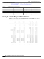
Specifying the Management Ethernet Interface Name in CLI Commands
Viewing the Available Management Ethernet Interfaces 3-34
Configuring the Management Ethernet Interface 3-35
Prerequisites 3-35
Examples 3-37
Related Documents 3-38
3-26
3-33
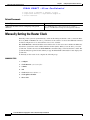
Manually Setting the Router Clock 3-38
Examples 3-39
Related Documents 3-40
Where to Go Next
CHAPTER
3-40
4
Contents
4-1
Configuring the Domain Name and Domain Name Server
Examples 4-3
Configuring Telnet and XML Host Services
Prerequisites 4-4
Examples 4-5
4-1
4-3
Cisco ASR 9000 Series Aggregation Services Router Getting Started Guide
OL-17502-01
3
Contents
FINAL DRAFT - Cisco Confidential
Managing Configuration History and Rollback 4-6
Viewing CommitIDs 4-7
Viewing Configuration Changes Recorded in a CommitID 4-7
Previewing Rollback Configuration Changes 4-8
Rolling Back the Configuration to a Specific Rollback Point 4-8
Rolling Back the Configuration over a Specified Number of Commits 4-9
Loading CommitID Configuration Changes to the Target Configuration 4-9
Loading Rollback Configuration Changes to the Target Configuration 4-10
Deleting CommitIDs 4-11
Configuring Logging and Logging Correlation 4-12
Logging Locations and Severity Levels 4-12
Alarm Logging Correlation 4-13
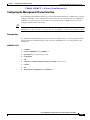
Configuring Basic Message Logging 4-13
Examples 4-14
Related Documents 4-15
Disabling Console Logging 4-15
Creating and Modifying User Accounts and User Groups 4-15
Viewing Details About User Accounts, User Groups, and Task IDs
Configuring User Accounts 4-17
Creating Users and Assigning Groups 4-17
Related Documents 4-18
Configuring Software Entitlement
4-19
Configuration Limiting 4-19
Static Route Configuration Limits 4-20
Examples 4-20
IS-IS Configuration Limits 4-20
Examples 4-20
OSPFv2 and v3 Configuration Limits 4-21
Examples 4-21
Routing Policy Language Line and Policy Limits
Examples 4-23
Multicast Configuration Limits 4-24
MPLS Configuration Limits 4-25
Other Configuration Limits 4-25
CHAPTER
4-16
4-23
5
Contents
5-1
CLI Tips and Shortcuts 5-1
Entering Abbreviated Commands
5-1
Cisco ASR 9000 Series Aggregation Services Router Getting Started Guide
4
OL-17502-01
Contents
FINAL DRAFT - Cisco Confidential
Using the Question Mark (?) to Display On-Screen Command Help
Completing a Partial Command with the Tab Key 5-4
Identifying Command Syntax Errors 5-4
Using the no Form of a Command 5-4
Editing Command Lines that Wrap 5-5
5-2
Viewing System Information with show Commands 5-5
Common show Commands 5-6
Browsing Display Output when the --More-- Prompt Appears 5-6
Halting the Display of Screen Output 5-7
Redirecting Output to a File 5-7
Narrowing Output from Large Configurations 5-8
Limiting show Command Output to a Specific Feature or Interface
Using Wildcards to Display All Instances of an Interface 5-8
Filtering show Command Output 5-9
Adding a Filter at the --More-- Prompt 5-10
Multipipe Support 5-11
Show Parser Dump Enhancement Feature 5-11
Wildcards, Templates, and Aliases 5-11
Using Wildcards to Identify Interfaces in show Commands
Example 5-12
Creating Configuration Templates 5-13
Examples 5-15
Applying Configuration Templates 5-15
Examples 5-15
Aliases 5-16
Keystrokes Used as Command Aliases 5-17
5-8
5-12
Command History 5-17
Viewing Previously Entered Commands 5-17
Recalling Previously Entered Commands 5-17
Recalling Deleted Entries 5-18
Redisplaying the Command Line 5-18
Key Combinations 5-18
Key Combinations to Move the Cursor 5-19
Keystrokes to Control Capitalization 5-19
Keystrokes to Delete CLI Entries 5-20
Transposing Mistyped Characters 5-20
CHAPTER
6
Contents
6-1
Cisco ASR 9000 Series Aggregation Services Router Getting Started Guide
OL-17502-01
5
Contents
FINAL DRAFT - Cisco Confidential
Additional Sources for Information
6-1
Basic Troubleshooting Commands 6-1
Using show Commands to Display System Status and Configuration 6-2
Using the ping Command 6-2
Examples 6-2
Using the traceroute Command 6-3
Examples 6-3
Using debug Commands 6-3
Viewing a List of Debug Features 6-4
Enabling Debugging for a Feature 6-4
Viewing Debugging Status 6-5
Disabling Debugging for a Service 6-5
Disabling Debugging for All Services Started at the Active Terminal Session
Disabling Debugging for All Services Started at All Terminal Sessions 6-6
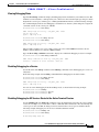
Configuration Error Messages 6-6
Configuration Failures During a Commit Operation
!Configuration Errors at Startup 6-7
6-5
6-6
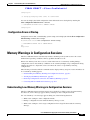
Memory Warnings in Configuration Sessions 6-7
Understanding Low-Memory Warnings in Configuration Sessions 6-7
“WARNING! MEMORY IS IN MINOR STATE” 6-8
“ERROR! MEMORY IS IN SEVERE (or CRITICAL) STATE” 6-8
Viewing System Memory Information 6-8
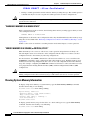
Removing Configurations to Resolve Low-Memory Warnings 6-9
Clearing a Target Configuration 6-10
Removing Committed Configurations to Free System Memory 6-10
Rolling Back to a Previously Committed Configuration 6-10
Clearing Configuration Sessions 6-11
Contacting TAC for Additional Assistance 6-11
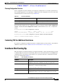
Interfaces Not Coming Up 6-11
Verifying System Interfaces 6-12
APPENDIX
A
Understanding Regular Expressions, Special Characters, and Patterns
Contents
A-1
A-1
Regular Expressions
Special Characters
A-1
A-2
Character Pattern Ranges
Multiple-Character Patterns
A-2
A-3
Cisco ASR 9000 Series Aggregation Services Router Getting Started Guide
6
OL-17502-01
Contents
FINAL DRAFT - Cisco Confidential
Complex Regular Expressions Using Multipliers
Pattern Alternation
A-4
Anchor Characters
A-4
Underscore Wildcard
A-3
A-4
Parentheses Used for Pattern Recall
A-4
Cisco ASR 9000 Series Aggregation Services Router Getting Started Guide
OL-17502-01
7
Contents
FINAL DRAFT - Cisco Confidential
Cisco ASR 9000 Series Aggregation Services Router Getting Started Guide
8
OL-17502-01
FINAL DRAFT - Cisco Confidential
Preface
This guide introduces the Cisco ASR 9000 Series Aggregation Services Router that runs
Cisco IOS XR Software. This guide also describes administration, maintenance, and troubleshooting
tasks that may be required after initially starting the router.
This preface contains the following sections:
•
Changes to This Document, page vii
•
About This Document, page vii
•
Obtaining Documentation and Submitting a Service Request, page ix
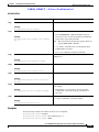
Changes to This Document
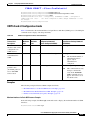
Table 1 lists technical changes made to this document since it was first released.
Table 1
Changes to This Document
Revision
Date
Change Summary
OL-17502-01
March 2009
Initial release of this document.
About This Document
The following sections provide information about Cisco ASR 9000 Series Aggregation Services Router
Getting Started Guide and related documents:
•
Intended Audience, page viii
•
Organization of the Document, page viii
•
Related Documents, page viii
•
Conventions, page viii
Cisco ASR 9000 Series Aggregation Services Router Getting Started Guide
OL-17502-01
vii
Preface
FINAL DRAFT - Cisco Confidential
Intended Audience
This document is intended for the following people:
•
Experienced service provider administrators
•
Cisco telecommunications management engineers
•
Third-party field service technicians who have completed the Cisco IOS XR Software training
sessions
•
Customers who daily use and manage routers running Cisco IOS XR Software
Organization of the Document
This document contains the following chapters:
•
Chapter 1, “Introducing to the Cisco ASR 9000 Series Aggregation Services Router”
•
Chapter 2, “Bringing Up Cisco IOS XR Software on the Router”
•
Chapter 3, “Configuring General Router Features”
•
Chapter 4, “Configuring Additional Router Features”
•
Chapter 5, “CLI Tips, Techniques, and Shortcuts”
•
Chapter 6, “Troubleshooting the Cisco IOS XR Software”
•
Appendix A, “Understanding Regular Expressions, Special Characters, and Patterns”
Related Documents
For a list of documentation for this router, see the following Web pages:
•
add links when created
•
add links when created
•
add links when created
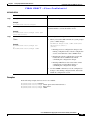
Conventions
This document uses the following conventions:
Item
Convention
Commands and keywords
boldface font
Variable for which you supply values
italic font
Displayed session and system information
screen
Commands and keywords you enter in an
interactive environment
boldface screen
font
font
Variables you enter in an interactive environment italic screen font
Cisco ASR 9000 Series Aggregation Services Router Getting Started Guide
viii
OL-17502-01
Preface
FINAL DRAFT - Cisco Confidential
Item
Convention
Menu items and button names
boldface font
Menu navigation
Option > Network Preferences
Note
Means reader take note. Notes contain helpful suggestions or references to material not covered in the
publication.
Tip
Means the following information will help you solve a problem. The information in tips might not be
troubleshooting or an action, but contains useful information.
Caution
Means reader be careful. In this situation, you might do something that could result in equipment
damage or loss of data.
Obtaining Documentation and Submitting a Service Request
For information on obtaining documentation, submitting a service request, and gathering additional
information, see the monthly What’s New in Cisco Product Documentation, which also lists all new and
revised Cisco technical documentation, at:
http://www.cisco.com/en/US/docs/general/whatsnew/whatsnew.html
Subscribe to the What’s New in Cisco Product Documentation as a Really Simple Syndication (RSS) feed
and set content to be delivered directly to your desktop using a reader application. The RSS feeds are a free
service and Cisco currently supports RSS version 2.0.
Cisco ASR 9000 Series Aggregation Services Router Getting Started Guide
OL-17502-01
ix
Preface
FINAL DRAFT - Cisco Confidential
Cisco ASR 9000 Series Aggregation Services Router Getting Started Guide
x
OL-17502-01
FINAL DRAFT —Cisco Confidential
CH A P T E R
1
Introducing to the Cisco ASR 9000 Series
Aggregation Services Router
This chapter introduces the Cisco ASR 9000 Series Aggregation Services Router that runs
Cisco IOS XR Software. It also introduces router concepts, features, and user interfaces.
Contents
•
Router Overview, page 1-1
•
System Configurations, page 1-6
•
Management and Security, page 1-8
•
Initial Router Configuration, page 1-9
•
Where to Go Next, page 1-13
Router Overview
The router is a multilayer Ethernet switching and aggregation platform. It is also a label edge router
(LER) that sits at the edge of a Multiprotocol Label Switching (MPLS) network. The router has links
that extend outside the MPLS network. It provides access and aggregation services for enterprise and
service providers.
Features and Capabilities
A scalable, carrier-class distributed forwarding router, the router is designed for the redundancy, high
security and availability, packaging, power and other requirements needed by service providers.
The router aggregates triple play and Ethernet service traffic from Gigabit Ethernet devices, aggregating
these services to 10 Gigabit Ethernet IP, MPLS edge, or core.
The following sections describe the features and capabilities in detail:
•
Cisco IOS XR Software, page 1-2
•
Flexible Ethernet, page 1-3
•
L2VPN, page 1-4
Cisco ASR 9000 Series Aggregation Services Router Getting Started Guide
OL-17502-01
1-1
Chapter 1
Introducing to the Cisco ASR 9000 Series Aggregation Services Router
Router Overview
FINAL DRAFT —Cisco Confidential
•
Multicast, page 1-4
•
OAM, page 1-4
•
Layer 3 routing, page 1-5
•
QoS, page 1-5
•
MPLS TE, page 1-5
•
Manageability, page 1-8
•
Security, page 1-9
•
Command-Line Interface, page 1-10
•
Extensible Markup Language API, page 1-10
•
Simple Network Management Protocol, page 1-10
Cisco IOS XR Software
The router runs Cisco IOS XR Software, this offers the following:
•
Modular software design: Cisco IOS XR Software represents a continuation of the Cisco networking
leadership in helping customers realize the power of their networks and the Internet. It provides
unprecedented routing-system scalability, high availability, service isolation, and manageability to
meet the mission-critical requirements of next-generation networks.
•
Operating system infrastructure protection: Cisco IOS XR Software provides a microkernel
architecture that forces all but the most critical functions, such as memory management and thread
distribution, outside of the kernel, thereby preventing failures in applications, file systems, and even
device drivers from causing widespread service disruption.
•
Process and thread protection: Each process—even individual process threads—is executed in its
own protected memory space, and communications between processes are accomplished through
well-defined, secure, and version-controlled application programming interfaces (APIs),
significantly minimizing the effect that any process failure can have on other processes.
•
Cisco In-Service Software Upgrade (ISSU): Cisco IOS XR Software modularity sustains system
availability during installation of a software upgrade. ISSUs or hitless software upgrades (HSUs)
allow you to upgrade most Cisco router software features without affecting deployed services. You
can target particular system components for upgrades based on software packages or composites that
group selected features. Cisco preconfigures and tests these packages and composites to help ensure
system compatibility.
•
Process restart: You can restart critical control-plane processes both manually and automatically in
response to a process failure versus restarting the entire operating system. This feature supports the
Cisco IOS XR Software goal of continuous system availability and allows for quick recovery from
process or protocol failures with minimal disruption to customers or traffic.
•
State checkpointing: You can maintain a memory and critical operating state across process restarts
in order to sustain routing adjacencies and signaling state during a route-switch-processor (RSP)
switchover.
•
Ethernet virtual connections (EVCs): Ethernet services are supported using individual EVCs to
carry traffic belonging to a specific service type or end user through the network. You can use
EVC-based services in conjunction with MPLS-based L2VPNs and native IEEE bridging
deployments.
Cisco ASR 9000 Series Aggregation Services Router Getting Started Guide
1-2
OL-17502-01
Chapter 1
Introducing to the Cisco ASR 9000 Series Aggregation Services Router
Router Overview
FINAL DRAFT —Cisco Confidential
•
Flexible VLAN classification: VLAN classification into Ethernet flow points (EFPs) includes
single-tagged VLANs, double-tagged VLANs (QinQ and IEEE 802.1ad), contiguous VLAN ranges,
and noncontiguous VLAN lists.
•
IEEE Bridging: The software supports native bridging based on IEEE 802.1Q, IEEE 802.1ad, and
QinQ VLAN encapsulation mechanisms on the router.
•
IEEE 802.1s Multiple Spanning Tree (MST): MST extends the IEEE 802.1w Rapid Spanning Tree
Protocol (MSTP) to multiple spanning trees, providing rapid convergence and load balancing.
•
MST Access Gateway: This feature provides a resilient, fast-convergence mechanism for
aggregating and connecting to Ethernet-based access rings.
•
Virtual Private LAN Services (VPLS): VPLS is a class of VPN that supports the connection of
multiple sites in a single, bridged domain over a managed IP/MPLS network. It presents an Ethernet
interface to customers, simplifying the LAN and WAN boundary for service providers and
customers, and enabling rapid and flexible service provisioning because the service bandwidth is
not tied to the physical interface. All services in a VPLS appear to be on the same LAN, regardless
of location.
•
Hierarchical VPLS (H-VPLS): H-VPLS provides a level of hierarchy at the edge of the VPLS
network for increased scale. QinQ access and H-VPLS pseudowire access options are supported.
•
Virtual Private WAN Services/Ethernet over MPLS (VPWS/EoMPLS): EoMPLS transports
Ethernet frames across an MPLS core using pseudowires. Individual EFPs or an entire port can be
transported over the MPLS backbone using pseudowires to an egress interface or subinterface.
•
Pseudowire redundancy: Pseudowire redundancy supports the definition of a backup pseudowire to
protect a primary pseudowire that fails.
•
Multisegment pseudowire stitching: Multisegment pseudowire stitching is a method for
interworking two pseudowires together to form a cross-connect relationship.
•
IPv4 Multicast: IPv4 Multicast supports Internet Group Management Protocol Versions 2 and 3
(IGMPv2/v3), Protocol Independent Multicast Source Specific Multicast (SSM) and Sparse Mode
(SM), Multicast Source Discovery Protocol (MSDP), and Anycast Rendezvous Point (RP).
•
IGMP v2/v3 Snooping: This Layer 2 mechanism efficiently tracks multicast membership on an
L2VPN network. Individual IGMP joins are snooped at the VLAN level or pseudowire level and
then summarizes results into a single upstream join message. In residential broadband deployments,
this feature enables the network to send only channels that are being watched to the downstream
users
Flexible Ethernet
The router uses Ethernet as its transport mechanism, this offers the following:
•
Ethernet virtual connections (EVCs): Ethernet services are supported using individual EVCs to
carry traffic belonging to a specific service type or end user through the network. You can use
EVC-based services in conjunction with MPLS-based L2VPNs and native IEEE bridging
deployments.
•
Flexible VLAN classification: VLAN classification into Ethernet flow points (EFPs) includes
single-tagged VLANs, double-tagged VLANs (QinQ and IEEE 802.1ad), contiguous VLAN ranges,
and noncontiguous VLAN lists.
•
IEEE Bridging: The software supports native bridging based on IEEE 802.1Q, IEEE 802.1ad, and
QinQ VLAN encapsulation mechanisms on the router.
•
IEEE 802.1s Multiple Spanning Tree (MST): MST extends the IEEE 802.1w Rapid Spanning Tree
Protocol (MSTP) to multiple spanning trees, providing rapid convergence and load balancing.
Cisco ASR 9000 Series Aggregation Services Router Getting Started Guide
OL-17502-01
1-3
Chapter 1
Introducing to the Cisco ASR 9000 Series Aggregation Services Router
Router Overview
FINAL DRAFT —Cisco Confidential
•
MST Access Gateway: This feature provides a resilient, fast-convergence mechanism for
aggregating and connecting to Ethernet-based access rings.
L2VPN
The router uses L2VPNs, this offers the following:
•
Virtual Private LAN Services (VPLS): VPLS is a class of VPN that supports the connection of
multiple sites in a single, bridged domain over a managed IP/MPLS network. It presents an Ethernet
interface to customers, simplifying the LAN and WAN boundary for service providers and
customers, and enabling rapid and flexible service provisioning because the service bandwidth is
not tied to the physical interface. All services in a VPLS appear to be on the same LAN, regardless
of location.
•
Hierarchical VPLS (H-VPLS): H-VPLS provides a level of hierarchy at the edge of the VPLS
network for increased scale. QinQ access and H-VPLS pseudowire access options are supported.
•
Virtual Private WAN Services/Ethernet over MPLS (VPWS/EoMPLS): EoMPLS transports
Ethernet frames across an MPLS core using pseudowires. Individual EFPs or an entire port can be
transported over the MPLS backbone using pseudowires to an egress interface or subinterface.
•
Pseudowire redundancy: Pseudowire redundancy supports the definition of a backup pseudowire to
protect a primary pseudowire that fails.
•
Multisegment pseudowire stitching: Multisegment pseudowire stitching is a method for
interworking two pseudowires together to form a cross-connect relationship.
Multicast
The router supports multicast, this offers the following:
•
IPv4 Multicast: IPv4 Multicast supports Internet Group Management Protocol Versions 2 and 3
(IGMPv2/v3), Protocol Independent Multicast Source Specific Multicast (SSM) and Sparse Mode
(SM), Multicast Source Discovery Protocol (MSDP), and Anycast Rendezvous Point (RP).
•
IGMP v2/v3 Snooping: This Layer 2 mechanism efficiently tracks multicast membership on an
L2VPN network. Individual IGMP joins are snooped at the VLAN level or pseudowire level and
then summarizes results into a single upstream join message. In residential broadband deployments,
this feature enables the network to send only channels that are being watched to the downstream
users.
OAM
The router supports different types of operations, administration, and maintenance (OAM), this offers
the following:
•
E-OAM (IEEE 802.3ah): Ethernet link layer OAM is a vital component of EOAM that provides
physical-link OAM to monitor link health and assist in fault isolation. Along with IEEE 802.1ag,
Ethernet link layer OAM can be used to assist in rapid link-failure detection and signaling to remote
end nodes of a local failure.
•
E-OAM (IEEE 802.1ag): Ethernet Connectivity Fault Management is a subset of EOAM that
provides numerous mechanisms and procedures that allow discovery and verification of the path
through IEEE 802.1 bridges and LANs.
•
MPLS OAM: This protocol supports label-switched-path (LSP) ping, LSP TraceRoute, and virtual
circuit connectivity verification (VCCV).
Cisco ASR 9000 Series Aggregation Services Router Getting Started Guide
1-4
OL-17502-01
Chapter 1
Introducing to the Cisco ASR 9000 Series Aggregation Services Router
Router Overview
FINAL DRAFT —Cisco Confidential
Layer 3 routing
The router runs Cisco IOS XR Software which supports Layer 3 routing and a range of IPv4 services
and routing protocols, including the following:
•
Intermediate System-to-Intermediate System (IS-IS)
•
Open Shortest Path First (OSPF)
•
static routing
•
IPv4 Multicast
•
Routing Policy Language (RPL)
•
Hot Standby Router Protocol (HSRP)
•
Virtual Router Redundancy Protocol (VRRP)
MPLS VPN
The router supports MPLS VPN, this offers the following:
•
MPLS L3VPN: The IP VPN feature for MPLS allows a Cisco IOS Software or Cisco IOS-XR
Software network to deploy scalable IPv4 Layer 3 VPN backbone services. An IP VPN is the
foundation that companies use for deploying or administering value-added services, including
applications and data hosting network commerce and telephony services to business customers.
•
Carrier Supporting Carrier (CSC): CSC allows a MPLS VPN service provider to connect
geographically isolated sites using another backbone service provider and still maintain a private
address space for its customer VPNs. It is implemented as defined by IETF RFC 4364.
QoS
The router supports many types of quality of service (QoS), this offers the following:
•
QoS: Comprehensive QoS support with up to 3 million queues, Class-Based Weighted Fair Queuing
(CBWFQ) based on a three-parameter scheduler, Weighted Random Early Detection (WRED),
two-level strict priority scheduling with priority propagation, and 2-rate, 3-color (2R3C) Policing
are all supported.
•
Cisco IOS XR Software: This software supports a rich variety of QoS mechanisms, including
policing, marking, queuing, dropping, and shaping. Additionally, the operating systems support
Modular QoS CLI (MQC). Modular CLI is used to configure various QoS features on various Cisco
platforms.
•
H-QoS: Four-level H-QoS support is provided for EVCs with the following hierarchy levels: port,
group of EFPs, EFP, and class of service. This level of support allows for per-service and per-end
user QoS granularity.
MPLS TE
The router supports MPLE TE, this offers the following:
•
MPLS TE: Cisco IOS XR Software supports MPLS protocols such as Traffic Engineering/Fast
Reroute (TE-FRR), Resource Reservation Protocol (RSVP), Label Distribution Protocol (LDP), and
Targeted Label Distribution Protocol (T-LDP).
Cisco ASR 9000 Series Aggregation Services Router Getting Started Guide
OL-17502-01
1-5
Chapter 1
Introducing to the Cisco ASR 9000 Series Aggregation Services Router
System Configurations
FINAL DRAFT —Cisco Confidential
•
MPLS TE Preferred Path: Preferred tunnel path functions let you map pseudowires to specific TE
tunnels. Attachment circuits are cross-connected to specific MPLS TE tunnel interfaces instead of
remote provider-edge router IP addresses (reachable using Interior Gateway Protocol [IGP] or Label
Distribution Protocol [LDP]).
High Availability
The router is intended for use in Enterprise networks that require high-availability. It is designed to
provide high MTBF (Mean Time Between Failures) and low MTTR (Mean Time To Resolve) rates. This
minimizes outages or and maximizes availability. The router achieves this using the following:
•
Component redundancy
– Duplex power supplies
– Cooling systems
•
Fault detection
•
Management features
•
High availability features
– Non-stop forwarding (NSF)—Cisco IOS XR Software supports forwarding without traffic loss
during a brief outage of the control plane through signaling and routing protocol
implementations for graceful restart extensions as standardized by the IETF, NSF requires
neighboring nodes to be NSF-aware.
– Process restartability (minimum disruption restart)
– Stateful switchovers
– In-service software upgrades
–
MPLS TE FRR
–
Bidirectional Forwarding Detection (BFD)
–
Standard IEEE 802.3ad link aggregation bundles
System Configurations
The router runs Cisco IOS XR Software on the following standalone chassis types, available in AC or
DC versions:
•
a 6-slot chassis
•
a 10-slot chassis
Cisco ASR 9000 Series Aggregation Services Router Getting Started Guide
1-6
OL-17502-01
Chapter 1
Introducing to the Cisco ASR 9000 Series Aggregation Services Router
System Configurations
FINAL DRAFT —Cisco Confidential
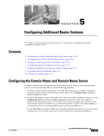
Figure 1-1
6-Slot Chassis
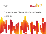
Figure 1-2
10-Slot Chassis
Each chassis type supports 40G per slot, and can share route-switch processors (RSPs) and line cards
(LCs), which are interchangeable. In each chassis, two slots are designated for RSPs, while the
remaining slots accommodate line cards that carry the traffic. The RSPs interconnect the line cards and
provide chassis management and control. Any line card can be used as a network-facing trunk card, a
subscriber-facing card, or it can provide any other form on connectivity.
The router uses the following line cards:
•
40x1GE Ethernet line card
•
4x10GE Ethernet line card
Cisco ASR 9000 Series Aggregation Services Router Getting Started Guide
OL-17502-01
1-7
Chapter 1
Introducing to the Cisco ASR 9000 Series Aggregation Services Router
Management and Security
FINAL DRAFT —Cisco Confidential
•
8x10GE Ethernet line card
Management and Security
In addition to the management and security features listed below, the router has administrative options,
like assigning Task IDs, that control who can perform router tasks.
Manageability
•
Command-Line Interface—The CLI is a user interface for monitoring and maintaining the router
and also for configuring basic router features.
•
Simple Network Management Protocol—SNMP is an application-layer protocol that facilitates
management information exchange between network devices.
•
MIBs—Management Information Bases are databases of objects that can be managed on a device.
MIBs include the following: IP-MIB (RFC4293), CISCO-BULK-FILE-MIB,
CISCO-CONFIG-COPY-MIB, CISCO-CONFIG-MAN-MIB, CISCO-ENHANCED-IMAGE-MIB,
CISCO-ENHANCED-MEMORY-POOL-MIB, CISCO-ENTITY-FRU-CONTROL-MIB,
CISCO-ENTITY-SENSOR-MIB, ENTITY-MIB, CISCO-ENTITY-ASSET-MIB,
ENTITY-STATE-MIB, ENTITY-SENSOR-MIB, CISCO-ENTITY-ALARM-MIB,
CISCO-FLASH-MIB, CISCO-IF-EXTENSION-MIB, CISCO-MEMORY-POOL-MIB,
CISCO-RF-MIB (1:1 RP Card), CISCO-SYSLOG-MIB, EVENT-MIB, IF-MIB as well as
RFC1213-MIB, SNMP-COMMUNITY-MIB, SNMP-FRAMEWORK-MIB,
SNMP-NOTIFICATION-MIB, SNMP-TARGET-MIB, IPv6-MIB, BRIDGE-MIB,
DOT3-OAM-MIB, CISCO-IETF-PW-MIB, CISCO-CLASS-BASED-QOS-MIB,
ETHERLIKE-MIB, BGP4-MIB Including Cisco extensions, MPLS TE STD MIB, TE-FRR-MIB,
and CISCO-IETF-IPMROUTE-MIB, IEEE-8021-CFM-MIB, DOT3-OAM-MIB
•
Trivial File Transfer Protocol—TFTP allows files to be transferred from one computer to another
over a network, usually without the use of client authentication (for example, username and
password).
•
Network Time Protocol—NTP synchronizes timekeeping among a set of distributed time servers.
•
Cisco IOS XR Software manageability: This feature provides industry-standard management
interfaces, including a modular command-line interface (CLI), Simple Network Management
Protocol (SNMP), and native XML interfaces.
•
Cisco Active Network Abstraction (ANA): Cisco ANA is a flexible, vendor-neutral network
resource-management solution for a multitechnology, multiservice network environment. Operating
between the network and the operations-support-system (OSS) layer, Cisco ANA aggregates virtual
network elements (VNEs) into a software-based virtual network, much as real network elements
create the real-world network. Cisco ANA dynamically discovers network components and tracks
the status of network elements in near real time. Cisco ANA offers service providers:
– Simplified integration of OSS applications with network information
– A flexible common infrastructure for managing network resources
– Consistent procedures and interfaces for all network elements
Cisco ASR 9000 Series Aggregation Services Router Getting Started Guide
1-8
OL-17502-01
Chapter 1
Introducing to the Cisco ASR 9000 Series Aggregation Services Router
Initial Router Configuration
FINAL DRAFT —Cisco Confidential
Security
•
Cisco IOS XR Software: This software provides comprehensive network security features, including
ACLs; control-plane protection; routing authentications; authentication, authorization, and
accounting (AAA); TACACS+; IP Security (IPSec); Secure Shell (SSH) Protocol; SNMPv3; and
leading Routing Policy Language (RPL) support.
•
Layer 2 ACLs: You can use this security feature to filter packets under an EVC based on MAC
addresses.
•
Layer 3 ACLs: This feature matches ACLs by IPv4 protocol packet attributes.
•
Security: Many critical security features are supported:
– Standard IEEE 802.1ad Layer 2 Control Protocol (L2CP) and bridge-protocol-data-unit
(BPDU) filtering
– MAC limiting per EFP or bridge domain
– Unicast, multicast, and broadcast storm control blocking on any interface or port
– Unknown Unicast Flood Blocking (UUFB)
– Dynamic Host Configuration Protocol (DHCP) Snooping
– Unicast Reverse Path Forwarding (URPF)
– Control-plane security
•
Secure Shell (SSH)
•
Authorization, Admission, Accounting (AAA)
•
Control Plane Policing (CoPP)
Initial Router Configuration
The initial configuration of the Cisco ASR 9000 Series Aggregation Services Router is determined
automatically by the software when you boot the router; you need not set up any general configuration
information. Also there is no explicit configuration needed to make a particular RSP active. It becomes
the active RSP when chosen automatically by the software upon boot.
Since there are not multiple RSP pairs in this router, the only RSP choices are RSP0 and RSP1. Typically,
the lower numbered slot is the chosen RSP. If that RSP is not available the software chooses the RSP in
the other slot as the route process controller, making it the primary RSP. During fail over or switch over,
the active role migrates to the standby RSP.
Management Interfaces
Although there is no need to set up general router configuration information, you do need to configure
management interfaces manually. Configure management ports on RSP0, RSP1, or both at the same
time:
•
Telnet
•
Secure Shell (SSH)
•
Console Server
The router provides different router management interfaces, described in the following sections:
Cisco ASR 9000 Series Aggregation Services Router Getting Started Guide
OL-17502-01
1-9
Chapter 1
Introducing to the Cisco ASR 9000 Series Aggregation Services Router
Initial Router Configuration
FINAL DRAFT —Cisco Confidential
•
Command-Line Interface, page 1-10
•
Extensible Markup Language API, page 1-10
•
Simple Network Management Protocol, page 1-10
Command-Line Interface
The CLI is a user interface for monitoring and maintaining the router and also for configuring basic
router features. Through the CLI you execute the Cisco IOS XR commands.
All procedures in this guide use CLI. Before you can use other router management interfaces, first use
the CLI to install and configure those interfaces. Guidelines for using CLI to configure the router are
discussed in the following chapters:
•
Chapter 3, “Configuring General Router Features”
•
Chapter 4, “Configuring Additional Router Features”
•
Chapter 5, “CLI Tips, Techniques, and Shortcuts”
For more CLI procedures, like hardware interface and software protocol management tasks, see the
Cisco IOS XR Software documents listed in “Related Documents” section on page viii.
Extensible Markup Language API
The Extensible Markup Language (XML) application programming interface (API) is an XML interface
used for rapid development of client applications and perl scripts to manage and monitor the router.
Client applications can configure the router or request status information from the router by encoding a
request in XML API tags and sending it to the router. The router processes the request and sends the
response to the client in the form of encoded XML API tags. The XML API supports readily available
transport layers, including Telnet, Secure Shell (SSH) and Secure Socket Layer (SSL) transport.
For more information, see the Cisco IOS XR Software documents listed in the “Related Documents”
section on page viii.
Simple Network Management Protocol
Simple Network Management Protocol (SNMP) is an application-layer protocol that facilitates
management information exchange between network devices. By using SNMP-transported data (such as
packets per second and network error rates), network administrators can manage network performance,
find and solve network problems, and plan for network growth.
The Cisco IOS XR Software supports SNMP v1, v2c, and v3. SNMP is part of a larger architecture
called the Internet Network Management Framework (NMF), which is defined in Internet documents
called RFCs. The SNMPv1 NMF is defined by RFCs 1155, 1157, and 1212, and the SNMPv2 NMF is
defined by RFCs 1441 through 1452. For more information on SNMP v3, see RFC 2272 and 2273.
SNMP is a popular protocol for managing diverse commercial internetworks and those used in
universities and research organizations. SNMP-related standardization activity continues even as
vendors develop and release state-of-the-art, SNMP-based management applications. SNMP is a
relatively simple protocol, yet its feature set is sufficiently powerful to handle the difficult problems
presented in trying to manage the heterogeneous networks of today.
For more information, see the Cisco IOS XR Software documents listed in the “Related Documents”
section on page viii.
Cisco ASR 9000 Series Aggregation Services Router Getting Started Guide
1-10
OL-17502-01
Chapter 1
Introducing to the Cisco ASR 9000 Series Aggregation Services Router
Initial Router Configuration
FINAL DRAFT —Cisco Confidential
Connecting to the Router Through the Console Port
The first time you connect to a new router with Cisco IOS XR software, connect through the Console
port. Although typical router configuration and management take place using an Ethernet port, you must
configure the console port for your LAN before it can be used.
Because a new router has no name, IP address, or other credentials, use a terminal to connect through
the Console port, setting the speed to 115200. The remote terminal setting has to match the 115200
value.
After you connect through the Console port, configure the management ports with their IP addresses.
Then you can use either SSH or Telnet to connect to the router.
Note
confreg 0x0 reverts to the default speed setting. If you change it from the default of 115200, you must
reset it afterwards.
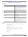
To connect to the router through the Console port, perform the following procedure.
SUMMARY STEPS
1.
Power on the router.
2.
Connect a terminal to the Console port.
3.
Start the terminal emulation program.
4.
Press Enter.
5.
Log in to the router.
6.
admin
7.
show dsc
Cisco ASR 9000 Series Aggregation Services Router Getting Started Guide
OL-17502-01
1-11
Chapter 1
Introducing to the Cisco ASR 9000 Series Aggregation Services Router
Initial Router Configuration
FINAL DRAFT —Cisco Confidential
DETAILED STEPS
Step 1
Step 2
Command or Action
Purpose
Power on the router.
Starts the router.
Connect a terminal to the Console port.
•
This step is required only if the power is not on.
•
For information on power installation and controls, see
the hardware documentation listed in the “Related
Documents” section on page viii.
Establishes a communications path to the router.
•
During the initial setup, you can communicate with the
router only through the Console port.
•
The router Console port is designed for a serial cable
connection to a terminal or a computer that is running a
terminal emulation program.
•
The terminal settings are:
– Bits per second: 115200
– Data bits: 8
– Parity: None
– Stop bit: 2
– Flow control: None
•
Step 3
Step 4
Start the terminal emulation program.
Press Enter.
For information on the cable requirements for the
Console port, see the hardware documentation listed in
the “Related Documents” section on page viii.
(Optional.) Prepares a computer for router communications.
•
The step is not required if you are connecting through a
terminal.
•
Terminals send keystrokes to and receive characters
from another device. If you connect a computer to the
Console port, you must use a terminal emulation
program to communicate with the router. For
instructions on using the terminal emulation program,
see the documentation for that program.
Initiates communication with the router.
•
If no text or router prompt appears when you connect to
the console port, press Enter to initiate
communications.
•
If no text appears when you press Enter, give the router
more time to complete the initial boot procedure, then
press Enter.
•
If the prompt gets lost among display messages, press
Enter again.
•
The router displays the prompt: Username:
Cisco ASR 9000 Series Aggregation Services Router Getting Started Guide
1-12
OL-17502-01
Chapter 1
Introducing to the Cisco ASR 9000 Series Aggregation Services Router
Where to Go Next
FINAL DRAFT —Cisco Confidential
Step 5
Step 6
Command or Action
Purpose
Log in to the router.
Establishes your access rights for the router management
session.
•
Type the root-system username and password or the
username and password provided by your system
administrator.
•
After you log in, the router displays the CLI prompt,
which is described in the “CLI Prompt” section on
page 3-6.
Places the router in administration EXEC mode.
admin
Example:
RP/0/RSP0/CPU0:router# admin
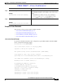
Step 7
Displays the RSP information for the router so that you can
verify that you have connected successfully to the console
port.
show dsc
Example:
RP/0/RSP0/CPU0:RO-A(admin)#sh dsc
NODE
ROLE
========================
0/RSP0/CPU0
DSC
0/RSP1/CPU0
Backup DSC
RP/0/RSP0/CPU0:RO-A(admin)#
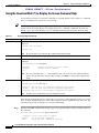
Configuring Gigabit Ethernet and 10-Gigabit Ethernet Interfaces
After connecting to the router, you need to configure Gigabit Ethernet and Ten Gigabit Ethernet
interfaces manually. Because these interfaces are for data traffic only, not management traffic, you
cannot use SSH or Telnet to an IP address that is part of the Gigabit Ethernet and 10-Gigabit Ethernet
interfaces.
Where to Go Next
Once you have logged into the router, you are ready to perform general router configuration as described
in Chapter 3, “Configuring General Router Features.”
Cisco ASR 9000 Series Aggregation Services Router Getting Started Guide
OL-17502-01
1-13
Chapter 1
Introducing to the Cisco ASR 9000 Series Aggregation Services Router
Where to Go Next
FINAL DRAFT —Cisco Confidential
Cisco ASR 9000 Series Aggregation Services Router Getting Started Guide
1-14
OL-17502-01
FINAL DRAFT —Cisco Confidential
CH A P T E R
2
Bringing Up Cisco IOS XR Software on the Router
This chapter provides instructions for bringing up Cisco IOS XR Software on the router for the first
time.
Contents
•
Prerequisites, page 2-1
•
Bringing Up and Configuring the Router, page 2-2
•
Verifying the System After Initial Boot, page 2-4
•
Where to Go Next, page 2-8
Prerequisites
The following sections describe the software and hardware requirements for bringing up the router
running Cisco IOS XR Software Release 3.7.
Cisco ASR 9000 Series Aggregation Services Router Getting Started Guide
OL-17502-01
2-1
Chapter 2
Bringing Up Cisco IOS XR Software on the Router
Bringing Up and Configuring the Router
FINAL DRAFT —Cisco Confidential
Software Requirements
The system requires compatible ROM Monitor firmware on all RPs.
Caution
The ROM Monitor firmware on all RPs must be compatible with the Cisco IOS XR Software release
installed on the router. If the router is brought up with an incompatible version of the ROM Monitor
software, the standby RP may fail to boot. For instructions to overcome a boot block in the standby RSP,
see the Cisco ASR 9000 Series Aggregation Series Router ROM Monitor Guide.
Hardware Prerequisites and Documentation
The Cisco IOS XR Software runs on the configuration listed in the “System Configurations” section on
page 1-6. Before a router can be started, the following hardware management procedures must be
completed:
•
Site preparation
•
Equipment unpacking
•
Router installation
For information on how to complete these procedures for your router equipment, see the hardware
documents listed in the “Related Documents” section on page viii.
Bringing Up and Configuring the Router
To bring up a standalone router, you need to connect to the router and configure the root-system
username and password as described in the following procedure:
SUMMARY STEPS
1.
Establish a connection to the Console port.
2.
Type the username for the root-system login and press Enter.
3.
Type the password for the root-system login and press Enter.
4.
Log in to the router.
Cisco ASR 9000 Series Aggregation Services Router Getting Started Guide
2-2
OL-17502-01
Chapter 2
Bringing Up Cisco IOS XR Software on the Router
Bringing Up and Configuring the Router
FINAL DRAFT —Cisco Confidential
DETAILED STEPS
Step 1
Command or Action
Purpose
Establish a connection to the Console port.
Initiates communication with the router.
•
For instructions on connecting to the Console port, see
the “Connecting to the Router Through the Console
Port” section on page 1-11.
•
When you have successfully connected to the router
through the Console port, the router displays the
prompt: Username:
Step 2
Type the username for the root-system login and press Sets the root-system username, which is used to log in to the
Enter.
router.
Step 3
Type the password for the root-system login and press Creates an encrypted password for the root-system
Enter.
username.
Note
Step 4
Retype the password for the root-system login and
press Enter.
Allows the router to verify that you have entered the same
password both times.
•
Step 5
Log in to the router.
This password can be changed with the secret
command.
If the passwords do not match, the router prompts you
to repeat the process.
Establishes your access rights for the router management
session.
•
Type the root-system username and password that were
created earlier in this procedure.
•
After you log in, the router displays the CLI prompt,
which is described in the “CLI Prompt” section on
page 3-6.
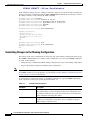
Examples
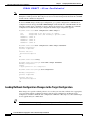
The following example shows the root-system username and password configuration for a new router,
and it shows the initial log in:
--- Administrative User Dialog --Enter root-system username: cisco
Enter secret:
Enter secret again:
RP/0/0/CPU0:Jan 10 12:50:53.105 : exec[65652]: %MGBL-CONFIG-6-DB_COMMIT :
'Administration configuration committed by system'. Use 'show configuration
commit changes 2000000009' to view the changes.
Use the 'admin' mode 'configure' command to modify this configuration.
User Access Verification
Username: cisco
Password:
RP/0/0/CPU0:ios#
Cisco ASR 9000 Series Aggregation Services Router Getting Started Guide
OL-17502-01
2-3
Chapter 2
Bringing Up Cisco IOS XR Software on the Router
Verifying the System After Initial Boot
FINAL DRAFT —Cisco Confidential
The secret line in the configuration command script shows that the password is encrypted. When you
type the password during configuration and login, the password is hidden.
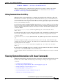
Verifying the System After Initial Boot
To verify the status of the router, perform the following procedure:
SUMMARY STEPS
1.
show version
2.
admin
3.
show platform [node-id]
4.
exit
5.
show redundancy
6.
show environment
DETAILED STEPS
Step 1
Command or Action
Purpose
show version
Displays information about the router, including image names,
uptime, and other system information.
Example:
RP/0/RSP0/CPU0:router# show version
Step 2
admin
Example:
Places the router in administration EXEC mode, displays
information about the status of cards and modules installed in
the router, and terminates administration EXEC mode.
RP/0/RSP0/CPU0:router# admin
Step 3
show platform [node-id]
Example:
RP/0/RSP0/CPU0:router# show platform
A card module is also called a node. When a node is working
properly, the status of the node in the State column is
IOS XR RUN.
Use the show platform node-id command to display
information for a specific node. Replace node-id with a node
name from the show platform command Node column.
Note
Step 4
exit
To view the status of all cards and modules, the show
platform command must be executed in administration
EXEC mode.
Exits the EXEC mode.
Example:
RP/0/RSP0/CPU0:router# exit
Cisco ASR 9000 Series Aggregation Services Router Getting Started Guide
2-4
OL-17502-01
Chapter 2
Bringing Up Cisco IOS XR Software on the Router
Verifying the System After Initial Boot
FINAL DRAFT —Cisco Confidential
Step 5
Command or Action
Purpose
show redundancy
Displays the state of the primary (active) and standby (inactive)
RPs, including the ability of the standby to take control of the
system.
Example:
•
RP/0/RSP0/CPU0:router# show redundancy
Step 6
If both RPs are working correctly, one node displays
active role, the Partner node row displays standby
role, and the Standby node row displays Ready.
Displays information about the hardware attributes and status.
show environment
Example:
RP/0/RSP0/CPU0:router# show environment
Examples of show Commands
The following sections provide examples of show commands:
•
show version Command: Example, page 2-5
•
show platform Command: Example, page 2-6
•
show redundancy Command: Example, page 2-6
•
show environment Command: Example, page 2-7
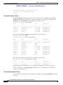
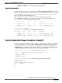
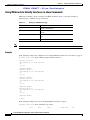
show version Command: Example
To view basic information about the router configuration, type the show version command in EXEC
mode, as shown in the following example:
RP/0/RSP0/CPU0:router# show version
Cisco IOS XR Software, Version 3.7.2.10I[FCI_DT_IMAGE]
Copyright (c) 2008 by Cisco Systems, Inc.
ROM: System Bootstrap, Version 0.63(20081010:215422) [ASR9K ROMMON],
router uptime is 1 week, 1 day, 10 hours, 31 minutes
System image file is "bootflash:disk0/asr9k-os-mbi-3.7.2.10I/mbiasr9k-rp.vm"
cisco ASR9K Series (MPC8641D) processor with 4194304K bytes of memory.
MPC8641D processor at 1333MHz, Revision 2.2
40 GigabitEthernet/IEEE 802.3 interface(s)
2 Ethernet/IEEE 802.3 interface(s)
12 TenGigabitEthernet/IEEE 802.3 interface(s)
219k bytes of non-volatile configuration memory.
975M bytes of compact flash card.
33994M bytes of hard disk.
1605616k bytes of disk0: (Sector size 512 bytes).
1605616k bytes of disk1: (Sector size 512 bytes).
Cisco ASR 9000 Series Aggregation Services Router Getting Started Guide
OL-17502-01
2-5
Chapter 2
Bringing Up Cisco IOS XR Software on the Router
Verifying the System After Initial Boot
FINAL DRAFT —Cisco Confidential
Configuration register on node 0/RSP0/CPU0 is 0x2
Boot device on node 0/RSP0/CPU0 is disk0:
--More--
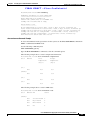
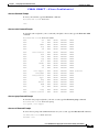
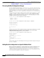
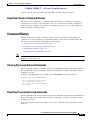
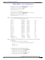
show platform Command: Example
The show platform command displays information on router resources. In EXEC mode, the show
platform command displays the resources assigned to the RP you are managing. In administration
EXEC mode, the show platform command displays all router resources.
RP/0/RSP0/CPU0:router# show platform
Node
Type
State
Config State
----------------------------------------------------------------------------0/RSP0/CPU0
A9K-RSP-4G-HDD(Active)
IOS XR RUN
PWR,NSHUT,MON
0/1/CPU0
A9K-40GE-B
IOS XR RUN
PWR,NSHUT,MON
0/4/CPU0
A9K-8T/4-B
IOS XR RUN
PWR,NSHUT,MON
0/6/CPU0
A9K-4T-B
IOS XR RUN
PWR,NSHUT,MON
The following administration EXEC mode example shows all router nodes:
RP/0/RSP0/CPU0:router# admin
RP/0/RSP0/CPU0:router(admin)# show platform
Node
Type
State
Config State
----------------------------------------------------------------------------0/RSP0/CPU0
A9K-RSP-4G-HDD(Active)
IOS XR RUN
0/FT0/SP
FAN TRAY
READY
PWR,NSHUT,MON
0/FT1/SP
FAN TRAY
READY
0/1/CPU0
A9K-40GE-B
IOS XR RUN
PWR,NSHUT,MON
0/4/CPU0
A9K-8T/4-B
IOS XR RUN
PWR,NSHUT,MON
0/6/CPU0
A9K-4T-B
IOS XR RUN
PWR,NSHUT,MON
0/PM0/SP
A9K-3KW-AC
READY
PWR,NSHUT,MON
0/PM1/SP
A9K-3KW-AC
READY
PWR,NSHUT,MON
0/PM2/SP
A9K-3KW-AC
READY
PWR,NSHUT,MON
The following example shows information for a single node in the router:
RP/0/RSP0/CPU0:router# show platform 0/1/CPU0
Node
Type
State
Config State
----------------------------------------------------------------------------0/1/CPU0
A9K-40GE-B
IOS XR RUN
PWR,NSHUT,MON
For more information on node IDs, see Cisco IOS XR System Management Configuration Guide.
For more information on the show platform command, see Cisco IOS XR Interface and Hardware
Component Command Reference.
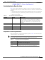
show redundancy Command: Example
To view information about the active and standby (inactive) RPs, type the show redundancy command
as follows:
Cisco ASR 9000 Series Aggregation Services Router Getting Started Guide
2-6
OL-17502-01
Chapter 2
Bringing Up Cisco IOS XR Software on the Router
Verifying the System After Initial Boot
FINAL DRAFT —Cisco Confidential
RP/0/RSP0/CPU0:router# show redundancy
Redundancy information for node 0/RSP0/CPU0:
==========================================
Node 0/RSP0/CPU0 is in ACTIVE role
Partner node (0/RSP1/CPU0) is in STANDBY role
Standby node in 0/RSP1/CPU0 is ready
Reload and boot info
---------------------RP reloaded Wed Feb 15 13:58:32 2008: 1 week, 6 days, 22 hours, 49 minutes ago
Active node booted Wed Feb 15 13:58:32 2008: 1 week, 6 days, 22 hours, 49 minutes ago
Standby node boot Wed Feb 15 13:59:00 2008: 1 week, 6 days, 22 hours, 49 minutes ago
Standby node last went not ready Wed Mar 1 07:40:00 2008: 5 hours, 8 minutes ago
Standby node last went ready Wed Mar 1 07:40:00 2008: 5 hours, 8 minutes ago
There have been 0 switch-overs since reload
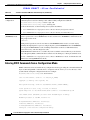
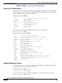
show environment Command: Example
To view environmental monitor parameters for the system, use the show environment command in
EXEC or administration EXEC mode.
Use the following command syntax:
show environment [options]
Type the show environment ? command to view the command options.
The following example shows a router’s temperature information:
RP/0/RSP0/CPU0:router# show environment temperatures
R/S/I
Modules
Inlet
Hotspot
Temperature
Temperature
(deg C)
(deg C)
0/1/*
host
28.1
35.7
host
24.0
33.5
host
26.7
35.0
host
30.0
39.1
0/RSP0/*
0/4/*
0/6/*
The following example shows a router’s LED status:
RP/0/RSP0/CPU0:router# show environment leds
R/S/I
Modules LED
Status
host
Critical-Alarm
0
host
Major-Alarm
0
host
Minor-Alarm
0
host
ACO
0
0/RSP0/*
Cisco ASR 9000 Series Aggregation Services Router Getting Started Guide
OL-17502-01
2-7
Chapter 2
Bringing Up Cisco IOS XR Software on the Router
Where to Go Next
FINAL DRAFT —Cisco Confidential
Where to Go Next
For information on configuring basic router features, see Chapter 3, “Configuring General Router
Features.”
Cisco ASR 9000 Series Aggregation Services Router Getting Started Guide
2-8
OL-17502-01
FINAL DRAFT —Cisco Confidential
CH A P T E R
3
Configuring General Router Features
This chapter describes how to communicate with the router using command-line interface (CLI). This
chapter also shows basic Cisco IOS XR Software configuration management.
Contents
•
Connecting to and Communicating with the Router, page 3-1
•
Logging In to a Router, page 3-5
•
Navigating Cisco IOS XR Software Command Modes, page 3-11
•
Managing Configuration Sessions, page 3-16
•
Configuring the Management Ethernet Interface, page 3-33
•
Manually Setting the Router Clock, page 3-38
•
Where to Go Next, page 3-40
Connecting to and Communicating with the Router
To use a router running Cisco IOS XR Software, first connect to it using a terminal or a PC. Before you
connect to the router, determine which entity to manage. You can manage router hardware or named
RSPs.
Connections are made through a direct physical connection to the Console port or through management
interfaces. To connect through the management interfaces, establish IP addresses and a default gateway.
The first time a router starts, use a direct connection to the Console port to type the configuration
information. When directly connected to the Console port, enter CLI commands at a terminal or
computer running terminal emulation software. This direct Console port connection is useful for
debugging as well.
Configure the Management Ethernet interface, described in the “Configuring the Management Ethernet
Interface” section on page 3-33. Router management and configuration can take place over an Ethernet
network connected to the Management Ethernet interface. Simple Network Management Protocol
(SNMP) agents also use the network connection.
You can use the modem connection for remote communications with the router. If the Management
Ethernet interface fails, the modem connection is an alternate path.
The following sections describe how to connect to the router:
Cisco ASR 9000 Series Aggregation Services Router Getting Started Guide
OL-17502-01
3-1
Chapter 3
Configuring General Router Features
Connecting to and Communicating with the Router
FINAL DRAFT —Cisco Confidential
•
Connecting Through the Console Port, page 3-2
•
Connecting Through a Terminal Server, page 3-3
•
Connecting Through the Management Ethernet Interface, page 3-5
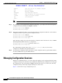
Connecting Through the Console Port
To connect to the router through the console port, perform the following procedure.
SUMMARY STEPS
1.
Identify the active RSP.
2.
Connect a terminal to the Console port of the active RSP.
3.
Start the terminal emulation program.
4.
Press Enter.
5.
Log in to the router.
DETAILED STEPS
Step 1
Command or Action
Purpose
Identify the active RSP.
Identifies the RSP to which you must connect in the next step.
There are two RSPs: RSP0 and RSP1. One is active RSP, the other is
standby.
Step 2
Connect a terminal to the Console port
of the active RSP.
Establishes a communications path to the router.
•
During initial setup, communicate with the router only through the
Console port of the active RSP.
•
The Console port uses a serial cable connection to a terminal or a
computer running terminal emulation.
•
The terminal settings are:
– Bits per second: 9600/11520
– Data bits: 8
– Parity: None
– Stop bit: 1
– Flow control: None
•
Step 3
Start the terminal emulation program.
For cable requirements for the Console port, see hardware
documentation listed in the “Related Documents” section on page viii.
(Optional) Prepares a computer for router communications.
•
The step is not required if you are connecting through a terminal.
•
Terminals send keystrokes to and receive characters from another
device. If you connect a computer to the Console port, use terminal
emulation to communicate with the router. For instructions on using a
terminal emulation program, see its documentation.
Cisco ASR 9000 Series Aggregation Services Router Getting Started Guide
3-2
OL-17502-01
Chapter 3
Configuring General Router Features
Connecting to and Communicating with the Router
FINAL DRAFT —Cisco Confidential
Step 4
Step 5
Command or Action
Purpose
Press Enter.
Initiates communication with the router.
Log in to the router.
•
If no text or router prompt appears when you connect to the Console
port, press Enter to initiate communications.
•
If no text appears when you press Enter and the router has been
started recently, give the router more time to complete the initial boot
procedure, then press Enter.
•
The router displays the prompt: Username:
Establishes your access rights for the router management session.
•
Type your username and password, as described in the “Logging In to
a Router” section on page 3-5.
•
After you log in, the router displays the CLI prompt, which is
described in the “CLI Prompt” section on page 3-6.
Connecting Through a Terminal Server
A terminal server connection provides a way to remotely access the Console port. It is less expensive to
connect to the router through the Management Ethernet interface (because you do not have the additional
cost of a terminal server). However, if you need to perform tasks that require Console port access from
a remote location, a terminal server is the best method.
The procedure for connecting to the router through a terminal server is similar to the procedure for
directly connecting through the Console port. For both connection types, the physical connection takes
place through the Console port. The difference is that the terminal server connects directly to the Console
port, and you must use a Telnet session to establish communications through the terminal server to the
router.
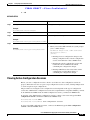
To establish a connection through a terminal server, perform the following procedure.
SUMMARY STEPS
1.
Install and configure the terminal server.
2.
Connect the terminal server to the Console port of the target RSP.
3.
Power on the router.
4.
Identify the target RSP.
5.
telnet access-server-address port
6.
Press Enter.
7.
Log in to the router.
Cisco ASR 9000 Series Aggregation Services Router Getting Started Guide
OL-17502-01
3-3
Chapter 3
Configuring General Router Features
Connecting to and Communicating with the Router
FINAL DRAFT —Cisco Confidential
DETAILED STEPS
Step 1
Step 2
Command or Action
Purpose
Install and configure the terminal
server.
Prepares the terminal server for communications with the router and with
Telnet clients.
Connect the terminal server to the
Console port of the target RSP.
•
This step is usually preformed once.
•
For router access, users need the Telnet server IP address and port
number for each RSP they access.
•
For additional information on configuring terminal services, including
terminal servers and templates, see the Cisco ASR 9000 Series
Aggregation Services Router System Management Configuration
Guide.
Establishes a communications path between the terminal server and the
router.
•
During the initial router setup, communicate with the router only
through the Console port of the primary RSP.
•
The router Console port uses a serial cable connection to a terminal or
terminal server.
•
The terminal settings are:
– Bits per second: 115200
– Data bits: 8
– Parity: None
– Stop bit: 1
– Flow control: None
•
Step 3
Step 4
Power on the router.
Identify the target RSP.
Starts the router.
•
This step is required only if the router power is not on.
•
For information on power installation and controls, see hardware
documentation listed in the “Related Documents” section on page viii.
Identifies the RSP to which you connect in the next step.
•
Step 5
telnet access-server-address port
For information on the cable requirements for the Console port, see
the hardware documentation listed in the “Related Documents”
section on page viii.
The Cisco ASR 9000 Series router has two RSPs: RSP0 and RSP1.
One is the active RSP, and the other is the standby.
Establishes a Telnet session with the terminal server.
•
Replace access-server-address with the IP address of the terminal
server, and replace port with the terminal server port number that
connects to the target RSP Console port.
Cisco ASR 9000 Series Aggregation Services Router Getting Started Guide
3-4
OL-17502-01
Chapter 3
Configuring General Router Features
Logging In to a Router
FINAL DRAFT —Cisco Confidential
Step 6
Step 7
Command or Action
Purpose
Press Enter.
(Optional) Initiates communications with the RSP.
Log in to the router.
•
If no text or router prompt appears when you start the Telnet session,
press Enter.
•
The router displays the prompt: Username:
Establishes your access rights for the router management session.
Type a username and password when prompted.
Connecting Through the Management Ethernet Interface
The Management Ethernet interface allows you to manage the router using a network connection. Before
using the Management Ethernet interface, configure it as described in the “Configuring the Management
Ethernet Interface” section on page 3-35.
Once configured, the network connection takes place between client software on a workstation computer
and a server process within the router. The type of client software you use depends on the server process
you want to use. The Cisco IOS XR Software supports the following client and server services:
•
Telnet clients can connect to a Telnet server in the router. The Telnet server is disabled by default
and can be enabled with the telnet ipv4 server command in global configuration mode.
•
Secure Shell (SSH) clients can connect to an SSH server in the router. The SSH server is disabled
by default and can be enabled with the ssh server command in global configuration mode. The SSH
server handles both Secure Shell Version 1 (SSHv1) and SSHv2 incoming client connections for
IPv4 address families.
To start a Telnet network connection, you start the Telnet client software with a command similar to the
following:
telnet ManagementEthernetInterfaceIPaddress
For specific instructions on connecting to the router through a Telnet or SSH client, see the instructions
for that software.
Ask your system administrator for the IP address of the Management Ethernet interface.
When the Telnet session is established, the router prompts you to log in, as described in the “Logging In
to a Router” section on page 3-5.
Logging In to a Router
The login process can require users to enter a password or a username and password before accessing
the router CLI. The user groups to which your username is assigned determine which commands you can
use.
Once you log in to the router, you can manage the entire router.
When you log in, the username and password may be validated by any of the following services:
•
Usernames configured on the router (username command in global configuration mode)
•
Root-system usernames that are configured
•
Passwords configured for the router console and auxiliary ports (password or secret command in
line configuration mode)
Cisco ASR 9000 Series Aggregation Services Router Getting Started Guide
OL-17502-01
3-5
Chapter 3
Configuring General Router Features
Logging In to a Router
FINAL DRAFT —Cisco Confidential
•
A Remote Authentication Dial In User Service (RADIUS) server
•
A Terminal Access Controller Access-Control System Plus (TACACS+) server
The username and password validation method that your router uses is determined by the router
configuration. For information on configuring username and password validation methods, see the Cisco
ASR 9000 Series Aggregation Services Router System Security Configuration Guide. For information on
which username and password to use, see your system administrator.
To log in to the router, enter your username and password when prompted. For example:
User Access Verification
Username: cisco
Password: password
RP/0/RSP0/CPU0:router#
Note
Passwords are case sensitive. If you want to log in to the router using a root-system username, type the
username in the following format: username@admin. To support admin login, local database
authentication must be enabled with the aaa authentication login remote local command. For more
information, see the Cisco ASR 9000 Series Aggregation Services Router System Security Configuration
Guide.
After you log in, the router displays the CLI prompt, which is described in the “CLI Prompt” section on
page 3-6. The command set that you can use is determined by the privileges assigned to your username.
For information on how privileges are assigned to usernames, see the Cisco ASR 9000 Series
Aggregation Services Router System Security Configuration Guide.
CLI Prompt
After you log in, you see the CLI prompt for Cisco IOS XR Software. This prompt identifies the router
to which you are issuing commands. The CLI prompt represents the path, through the router, to the CPU
that executes the commands you enter. The syntax for the CLI prompt is: type/rack/slot/module:
router-name#. The CLI prompt is described in Table 3-1.
Table 3-1
CLI Prompt Description
Prompt Syntax Components
Description
type
Type of interface or card with which you are communicating. For
most user communication tasks, the type is “RP.”
rack
Rack number. In a standalone router, the rack number is always “0.”
slot
Slot in which the RSP is installed. In a Cisco ASR 9000 Series router,
the RSP physical slot number is “RSP0” or “RSP1.”
module
Entity on a card that executes user commands or communicates with
a port (interface). For executing commands from the EXEC prompt,
the module is the “CPU0” of the RP. “CPU0” also controls the
forwarding and operating system (OS) functions for the system.
router-name
Hostname of the router. The hostname is usually defined during
initial configuration of the router, as described in the “Configuring
the RSP Hostname” section on page 3-32.
Cisco ASR 9000 Series Aggregation Services Router Getting Started Guide
3-6
OL-17502-01
Chapter 3
Configuring General Router Features
Logging In to a Router
FINAL DRAFT —Cisco Confidential
For example, the following prompt indicates that the CLI commands are executed on the RP in rack 0,
slot RSP0, by the “CPU0” module on a router named “router:”
RP/0/RSP0/CPU0:router#
User Access Privileges
When you log in to the router, your username and password are used to determine if you are authorized
to access the router. After you successfully log in, your username is used to determine which commands
you are allowed to use. The following sections provide information on how the router determines which
commands you can use:
•
User Groups, Task Groups, and Task IDs, page 3-7
•
Predefined User Groups, page 3-8
•
Viewing Your User Groups and Task IDs, page 3-8
User Groups, Task Groups, and Task IDs
The Cisco IOS XR software ensures security by combining tasks a user wants to perform (task IDs) into
groups, defining which router configuration and management functions users can perform. This policy
is enabled by the definition of:
•
User groups—A collection of users that share similar authorization rights on a router.
•
Task groups—Defined by a collection of task IDs for each class of action.
•
Task IDs—Define permission to perform particular tasks; pooled into a task group that is then
assigned to users.
The commands each user can perform are defined by the user groups to which he or she belongs.
Commands for a particular feature, like access control lists, are assigned to tasks. Each task is uniquely
identified by a task ID. If a user wants to use a particular command, his or her username must be
associated with the appropriate task ID. The association between a username and a task ID takes place
through two intermediate entities, the user group and task group.
The user group is a logical container used to assign the same task IDs to multiple users. Instead of
assigning task IDs to each user, assign them to the user group. Then assign users to that user group. When
a task is assigned to a user group, define the access rights for the commands associated with that task.
These rights include “read,” “write,” “execute,” and “notify.”
The task group is also a logical container, but it groups tasks. Instead of assigning task IDs to each user
group, you assign them to a task group. This allows you to quickly enable access to a specific set of tasks
by assigning a task group to a user group. Users are not assigned to groups by default and must be
explicitly assigned by an administrator.
Note
Only root-system users (root-lr users) or users associated with the WRITE:AAA task ID can configure
task groups.
Cisco ASR 9000 Series Aggregation Services Router Getting Started Guide
OL-17502-01
3-7
Chapter 3
Configuring General Router Features
Logging In to a Router
FINAL DRAFT —Cisco Confidential
Predefined User Groups
Cisco IOS XR Software includes a set of predefined user groups that meets the needs of most
organizations. These groups are described in Table 3-2.
Table 3-2
Predefined User Group Descriptions
User Group
Privileges
root-system
Display and execute all commands for all RPs in the system.
root-lr
Display and execute all commands within a single RP.
sysadmin
Perform system administration tasks for the router, such as
maintaining where the core dumps are stored or setting up the Network
Time Protocol (NTP) clock.
netadmin
Configure network protocols, like Open Shortest Path First (OSPF)
(usually used by network administrators).
operator
Perform day-to-day monitoring activities, and have limited
configuration rights.
cisco-support
Debug and troubleshoot features (usually, used by Cisco Technical
Support personnel).
For information on configuring user groups, see Cisco ASR 9000 Series Aggregation Services Router
System Security Configuration Guide..
Viewing Your User Groups and Task IDs
To view user groups and task IDs associated with your account, enter show user in EXEC mode.
Table 3-3 summarizes this command’s options.
Table 3-3
Account Information Options
Command
Description
show user
Displays your user name
show user tasks
Displays the task IDs assigned to your account
show user group
Displays the user groups assigned to your account
show user all
Displays all user groups and task ID information for your account
show aaa usergroup group-name
Displays the task IDs assigned to a user group
Examples
The following examples illustrate how to view user privileges:
•
show user Command: Example, page 3-9
•
show user tasks Command: Example, page 3-9
•
show user group Command: Example, page 3-9
•
show user all Command: Example, page 3-9
•
show aaa usergroup Command: Example, page 3-10
Cisco ASR 9000 Series Aggregation Services Router Getting Started Guide
3-8
OL-17502-01
Chapter 3
Configuring General Router Features
Logging In to a Router
FINAL DRAFT —Cisco Confidential
show user Command: Example
To view your username, type the show user command:
RP/0/RSP0/CPU0:router# show user
cisco
show user tasks Command: Example
To view the tasks assigned to your account and your rights to those tasks, type the show user tasks
command:
RP/0/RSP0/CPU0:router# show user tasks
Task:
aaa
: READ
WRITE
EXECUTE
DEBUG
Task:
acl
: READ
WRITE
EXECUTE
DEBUG
Task:
admin
: READ
WRITE
EXECUTE
DEBUG
Task:
ancp
: READ
WRITE
EXECUTE
DEBUG
Task:
atm
: READ
WRITE
EXECUTE
DEBUG
Task:
basic-services
: READ
WRITE
EXECUTE
DEBUG
Task:
bcdl
: READ
WRITE
EXECUTE
DEBUG
Task:
bfd
: READ
WRITE
EXECUTE
DEBUG
Task:
bgp
: READ
WRITE
EXECUTE
DEBUG
Task:
boot
: READ
WRITE
EXECUTE
DEBUG
Task:
bundle
: READ
WRITE
EXECUTE
DEBUG
Task:
cdp
: READ
WRITE
EXECUTE
DEBUG
Task:
cef
: READ
WRITE
EXECUTE
DEBUG
Task:
cisco-support
: READ
WRITE
EXECUTE
DEBUG (reserved)
Task:
config-mgmt
: READ
WRITE
EXECUTE
DEBUG
Task:
config-services
: READ
WRITE
EXECUTE
DEBUG
Task:
crypto
: READ
WRITE
EXECUTE
DEBUG
Task:
diag
: READ
WRITE
EXECUTE
DEBUG
Task:
drivers
: READ
WRITE
EXECUTE
DEBUG
Task:
dwdm
: READ
WRITE
EXECUTE
DEBUG
Task:
eem
: READ
WRITE
EXECUTE
DEBUG
Task:
eigrp
: READ
WRITE
EXECUTE
DEBUG
Task:
ethernet-services
: READ
WRITE
EXECUTE
DEBUG
show user group Command: Example
To view the user groups assigned to your user account, type the show user group command:
RP/0/RSP0/CPU0:router# show user group
root-system, cisco-support
show user all Command: Example
To view all user groups and task ID information for your account, type the show user all command:
P/0/RSP0/CPU0:router# show user all
Username: cisco
Cisco ASR 9000 Series Aggregation Services Router Getting Started Guide
OL-17502-01
3-9
Chapter 3
Configuring General Router Features
Logging In to a Router
FINAL DRAFT —Cisco Confidential
Groups: root-system, cisco-support
Authenticated using method local
User cisco has the following Task ID(s):
Task:
aaa
: READ
WRITE
EXECUTE
DEBUG
Task:
acl
: READ
WRITE
EXECUTE
DEBUG
Task:
admin
: READ
WRITE
EXECUTE
DEBUG
Task:
ancp
: READ
WRITE
EXECUTE
DEBUG
Task:
atm
: READ
WRITE
EXECUTE
DEBUG
Task:
basic-services
: READ
WRITE
EXECUTE
DEBUG
Task:
bcdl
: READ
WRITE
EXECUTE
DEBUG
Task:
bfd
: READ
WRITE
EXECUTE
DEBUG
Task:
bgp
: READ
WRITE
EXECUTE
DEBUG
Task:
boot
: READ
WRITE
EXECUTE
DEBUG
Task:
bundle
: READ
WRITE
EXECUTE
DEBUG
Task:
cdp
: READ
WRITE
EXECUTE
DEBUG
Task:
cef
: READ
WRITE
EXECUTE
DEBUG
Task:
cisco-support
: READ
WRITE
EXECUTE
DEBUG (reserved)
Task:
config-mgmt
: READ
WRITE
EXECUTE
DEBUG
Task:
config-services
: READ
WRITE
EXECUTE
DEBUG
Task:
crypto
: READ
WRITE
EXECUTE
DEBUG
Task:
diag
: READ
WRITE
EXECUTE
DEBUG
--More--
show aaa usergroup Command: Example
To view the rights assigned to a user group, type the show aaa usergroup group-name command:
RP/0/RSP0/CPU0:router# show aaa usergroup root-system
User group 'root-system'
Inherits from task group 'root-system'
User group 'root-system' has the following combined set
of task IDs (including all inherited groups):
Task:
aaa
: READ
WRITE
EXECUTE
DEBUG
Task:
acl
: READ
WRITE
EXECUTE
DEBUG
Task:
admin
: READ
WRITE
EXECUTE
DEBUG
Task:
ancp
: READ
WRITE
EXECUTE
DEBUG
Task:
atm
: READ
WRITE
EXECUTE
DEBUG
Task:
basic-services
: READ
WRITE
EXECUTE
DEBUG
Task:
bcdl
: READ
WRITE
EXECUTE
DEBUG
Task:
bfd
: READ
WRITE
EXECUTE
DEBUG
Task:
bgp
: READ
WRITE
EXECUTE
DEBUG
Task:
boot
: READ
WRITE
EXECUTE
DEBUG
Task:
bundle
: READ
WRITE
EXECUTE
DEBUG
Task:
cdp
: READ
WRITE
EXECUTE
DEBUG
Task:
cef
: READ
WRITE
EXECUTE
DEBUG
Cisco ASR 9000 Series Aggregation Services Router Getting Started Guide
3-10
OL-17502-01
Chapter 3
Configuring General Router Features
Navigating Cisco IOS XR Software Command Modes
FINAL DRAFT —Cisco Confidential
Task:
config-mgmt
: READ
WRITE
EXECUTE
DEBUG
Task:
config-services
: READ
WRITE
EXECUTE
DEBUG
Task:
crypto
: READ
WRITE
EXECUTE
DEBUG
Task:
diag
: READ
WRITE
EXECUTE
DEBUG
Task:
drivers
: READ
WRITE
EXECUTE
DEBUG
--More--
Navigating Cisco IOS XR Software Command Modes
The Cisco IOS XR Software CLI has different command modes. Each mode provides access to a subset
of commands used to configure, monitor, and manage the router. Access to a mode is determined by your
user group. The following sections describe the navigation of the command modes:
•
Identifying the Command Mode in the CLI Prompt, page 3-12
•
Common Command Modes, page 3-12
•
Entering EXEC Commands from a Configuration Mode, page 3-14
•
Command Mode Navigation Example, page 3-15
Figure 3-1 shows the basic command mode navigation for the CLI. Only a sample of possible submodes
is shown.
Figure 3-1
Example of Command Mode Navigation in Cisco IOS XR Software
Login
EXEC mode
Administration EXEC mode
Administration configuration mode
Logical router configuration submode
Global configuration mode
Configuration submode
examples
Interface
configuration submode
Router
configuration submode
Task group
configuration submode
149947
Line template
configuration submode
Cisco ASR 9000 Series Aggregation Services Router Getting Started Guide
OL-17502-01
3-11
Chapter 3
Configuring General Router Features
Navigating Cisco IOS XR Software Command Modes
FINAL DRAFT —Cisco Confidential
Identifying the Command Mode in the CLI Prompt
The command mode is identified in the CLI prompt after the router name.
When the router enters global configuration mode from the EXEC mode, the CLI prompt changes to
include “(config)” after the router name:
RP/0/RSP0/CPU0:router# configure
RP/0/RSP0/CPU0:router(config)#
When the router enters interface configuration submode, the prompt changes to include “(config-if)”
after the router name:
RP/0/RSP0/CPU0:router(config)# interface tunnel-te 2
RP/0/RSP0/CPU0:router(config-if)#
Common Command Modes
Table 3-4 summarizes the most common command modes of Cisco IOS XR Software and associated CLI
prompts.
Table 3-4
Common Command Modes and CLI Prompts
Command Mode
Description
EXEC
Logging in to an RP running the Cisco IOS XR Software automatically places the router in EXEC
mode.
Example:
RP/0/RSP0/CPU0:router#
EXEC mode enables a basic set of commands to display the operational state of an RP and the
Cisco IOS XR Software. Most CLI commands in EXEC mode do not change the RP operation. The
most common EXEC commands are show commands (to display RP configuration or operational
data) and clear commands (to clear or reset RP counters).
In EXEC mode, you can view the configuration of an RP but not the configuration of the system. The
difference is that RSPs are defined in administration configuration mode, which is a submode of
administration EXEC mode. RPs are configured in global configuration mode.
Additional commands are available depending on the access privileges (user groups) assigned to
your username. Minimal privileges also include a small set of EXEC commands for connecting to
remote devices, changing terminal line settings on a temporary basis, and performing basic tests.
Administration EXEC Administration EXEC mode is used to manage system resources. In administration EXEC mode, you
can view the configuration of the system but not the configuration of an RP. The difference is that
RPs are defined in administration configuration mode, which is a submode of administration EXEC
mode. RPs are configured in global configuration mode.
Administration EXEC mode is used primarily to view system-wide parameters, configure the
administration plane over the control Ethernet, and configure the RP. These operations are available
only to users with the required root level access.
From EXEC mode, use the admin command to enter administration EXEC mode:
RP/0/RSP0/CPU0:router# admin
RP/0/RSP0/CPU0:router(admin)#
Cisco ASR 9000 Series Aggregation Services Router Getting Started Guide
3-12
OL-17502-01
Chapter 3
Configuring General Router Features
Navigating Cisco IOS XR Software Command Modes
FINAL DRAFT —Cisco Confidential
Table 3-4
Common Command Modes and CLI Prompts (continued)
Command Mode
Description
administration
configuration mode
Administration configuration mode allows you to assign system resources to RSPs.
From administration EXEC mode, use the configure command to enter administration configuration
submode:
RP/0/RSP0/CPU0:router(admin)# configure
RP/0/RSP0/CPU0:router(admin-config)#
Global configuration
Global configuration mode is the starting point for RSP configuration. Commands entered in this
mode affect the RSP as a whole, rather than just one protocol or interface. Global configuration mode
is also used for entering configuration submodes to configure specific elements, such as interfaces
or protocols.
To enter global configuration mode, type the configure command at the EXEC command prompt:
RP/0/RSP0/CPU0:router# configure
RP/0/RSP0/CPU0:router(config)#
Note
Configuration
submodes
The system prompt changes to “router(config)” to indicate that the router is now in global
configuration mode.
From the global configuration mode you can enter more specific command modes. These are
available based on your access privileges and include protocol-specific, platform-specific, and
feature-specific configuration modes.
In the following example, MPLS LDP configuration mode is entered from global configuration
mode. The prompt for MPLS LDP configuration submode appears as config-ldp. The following
command syntax is used for entering configuration MPLS LDP submode:
RP/0/RSP0/CPU0:router# configure
RP/0/RSP0/CPU0:router(config)# mpls ldp
RP/0/RSP0/CPU0:router(config-ldp)#
Note
The availability of any particular mode depends on the router features and the access rights
of the individual user. For example, a configuration mode for configuring access servers is
not available on most routers.
Interface configuration The interface configuration submode is used to select and configure a hardware interface. To enter
interface configuration mode from global configuration mode, use an interface command. An
interface configuration command always follows an interface global configuration command, which
defines the interface type.
RP/0/RSP0/CPU0:router(config)# interface tunnel-te 2
RP/0/RSP0/CPU0:router(config-if)#
Router configuration
The router configuration submode is used to select and configure a routing protocol, like OSPF, or
IS-IS. The following command syntax is used for entering router configuration submode: router
protocol [protocol_options]
Replace protocol with the keyword for the protocol you want to configure. Replace protocol_options
with any keywords and arguments required for that protocol.
RP/0/RSP0/CPU0:router(config)# router ospf 100
RP/0/RSP0/CPU0:router(config-ospf)#
Cisco ASR 9000 Series Aggregation Services Router Getting Started Guide
OL-17502-01
3-13
Chapter 3
Configuring General Router Features
Navigating Cisco IOS XR Software Command Modes
FINAL DRAFT —Cisco Confidential
Table 3-4
Common Command Modes and CLI Prompts (continued)
Command Mode
Description
Router submode
configuration
Router configuration submodes are accessed from router configuration mode. The following
command syntax is used for entering router address family configuration submode:
RP/0/RSP0/CPU0:router(config)# router ospf 100
RP/0/RSP0/CPU0:router(config-ospf)# security ttl
For more information, see the following Cisco Systems documents:
ROM Monitor
(ROMMON) mode
•
Cisco ASR 9000 Series Aggregation Services Router Routing Configuration Guide
•
Cisco ASR 9000 Series Aggregation Services Router Routing Command Reference
The ROM Monitor is a bootstrap program that initializes the hardware and boots the system when a
router is powered on or reset. ROM Monitor mode is also known as “ROMMON,” which reflects the
CLI prompt for the mode.
rommon B1>
During normal operation, users do not interact with ROMMON. This mode is accessed only by
manually interrupting the boot process and placing the system in ROMMON. Once in ROMMON,
you can perform ROM Monitor tasks, including reinstallation of the Cisco IOS XR Software,
password recovery, and other diagnostic tasks.
The ROM Monitor CLI mode is accessible only from a terminal connected directly to the Console
port of the primary RSP, a terminal-modem connection to the AUX port, or through a terminal server.
See Cisco ASR 9000 Series Aggregation Services Router ROM Monitor Guide for information and
instructions on using ROM Monitor mode.
Entering EXEC Commands from a Configuration Mode
EXEC commands can be executed from any configuration mode by preceding the command with the do
keyword. Executing EXEC commands from a configuration mode allows you to view the state of the
system without exiting the configuration mode. For example:
RP/0/RSP0/CPU0:router(config)# do show version
Cisco IOS XR Software, Version 3.7.2.10I[FCI_DT_IMAGE]
Copyright (c) 2008 by Cisco Systems, Inc.
ROM: System Bootstrap, Version 0.63(20081010:215422) [ASR9K ROMMON],
router uptime is 1 week, 1 day, 11 hours, 47 minutes
System image file is "bootflash:disk0/asr9k-os-mbi-3.7.2.10I/mbiasr9k-rp.vm"
cisco ASR9K Series (MPC8641D) processor with 4194304K bytes of memory.
MPC8641D processor at 1333MHz, Revision 2.2
40 GigabitEthernet/IEEE 802.3 interface(s)
2 Ethernet/IEEE 802.3 interface(s)
12 TenGigabitEthernet/IEEE 802.3 interface(s)
219k bytes of non-volatile configuration memory.
Cisco ASR 9000 Series Aggregation Services Router Getting Started Guide
3-14
OL-17502-01
Chapter 3
Configuring General Router Features
Navigating Cisco IOS XR Software Command Modes
FINAL DRAFT —Cisco Confidential
975M bytes of compact flash card.
33994M bytes of hard disk.
1605616k bytes of disk0: (Sector size 512 bytes).
1605616k bytes of disk1: (Sector size 512 bytes).
Configuration register on node 0/RSP0/CPU0 is 0x2
Boot device on node 0/RSP0/CPU0 is disk0:
--More--
Command Mode Navigation Example
The following steps provide an example of command mode navigation:
Step 1
Start a session by logging in to the router and entering EXEC mode, as shown in the following example:
router is now available
Press Enter to get started.
User Access Verification
Username: asr9k
Password:<secret>
RP/0/RSP0/CPU0:router#
From EXEC mode you can issue EXEC commands or enter global configuration mode. Examples of
EXEC commands are the show commands used to display system status and clear commands to clear
counters or interfaces.
Step 2
Add a question mark at the end of the prompt, or after a command, to display the available options:
RP/0/RSP0/CPU0:router# show ?
aaa
Show AAA configuration and operational data
access-lists
Access lists
access-lists
access lists
adjacency
Adjacency information
af-ea
AF-EA Platform details
aliases
Display alias commands
ancp
Access Node Control Protocol show commands
app-obj
APP-OBJ Show Commands
arm
IP ARM information
arp
ARP show commands
arp-gmp
ARP show commands
asic-errors
ASIC error information
atc
Attractor Cache related
attractor
Show commands for attractor process
attribute
IM Attributes operations information
auto-rp
Auto-RP Commands
bcdl
Show Bulk Content DownLoader information
Cisco ASR 9000 Series Aggregation Services Router Getting Started Guide
OL-17502-01
3-15
Chapter 3
Configuring General Router Features
Managing Configuration Sessions
FINAL DRAFT —Cisco Confidential
bcm8705
Show trace data for the bcm8705 component
bfd
BFD information
bgp
BGP show commands
bridgemib
show bridge-mib component
bundle
Show information for bundles interfaces.
calendar
Display the system calendar
cdp
CDP information
--More--
Note
Step 3
The commands available to you depend on the router mode and your user group assignments.
If you belong to a user group that has configuration privileges, you can place the router in the global
configuration mode by entering the configure command:
RP/0/RSP0/CPU0:router# configure
RP/0/RSP0/CPU0:router(config)#
Step 4
From global configuration mode, you can place the router in a configuration submode, such as interface
configuration mode or a protocol-specific configuration mode.
RP/0/RSP0/CPU0:router# configure
RP/0/RSP0/CPU0:router(config)# mpls ldp
RP/0/RSP0/CPU0:router(config-ldp)#
In the following example, the router enters interface configuration mode and the user selects an MPLS
Traffic Engineering Tunnel interface for configuration.
RP/0/RSP0/CPU0:router(config)# interface tunnel-te 2
RP/0/RSP0/CPU0:router(config-if)#
The command mode prompt changes from (config) to (config-if) and you can now enter
configuration commands for the specified interface.
Step 5
To exit interface configuration mode and return to global configuration mode, type the exit command.
To return to EXEC mode, type the end command.
Managing Configuration Sessions
With the Cisco IOS XR Software, you cannot change the running (active) configuration directly. Enter
configuration changes into an inactive target configuration. When the target configuration is ready, apply
that configuration to the router with the commit command. This allows you to make, edit, and verify
configuration changes before impacting the running state of the router.
Figure 3-2 shows the two-stage configuration process.
Cisco ASR 9000 Series Aggregation Services Router Getting Started Guide
3-16
OL-17502-01
Chapter 3
Configuring General Router Features
Managing Configuration Sessions
FINAL DRAFT —Cisco Confidential
Figure 3-2
EXEC mode
Two-Stage Configuration Process
Global
configuration
mode
Stage 1:
Enter configuration
changes or load a
saved configuration.
Administration
mode
Stage 2:
"Commit" changes
to the running
configuration.
Administration
configuration
mode
149946
Save configuration
changes to a file.
Global configuration mode configures RSP-level features, such as routing protocols and interfaces.
Administration configuration mode assigns hardware components to RSPs.
The following sections describe management options for configuration sessions:
•
Entering Configuration Changes, page 3-17
•
Viewing Active Configuration Sessions, page 3-19
•
Starting a Configuration Session, page 3-20
•
Starting an Exclusive Configuration Session, page 3-21
•
Viewing Configuration Details, page 3-21
•
Saving the Target Configuration to a File, page 3-26
•
Loading the Target Configuration from a File, page 3-27
•
Loading an Alternative Configuration at System Startup, page 3-27
•
Clearing All Changes to a Target Configuration, page 3-27
•
Committing Changes to the Running Configuration, page 3-28
•
Exiting a Configuration Submode, page 3-31
•
Returning Directly to Configuration Mode from a Submode, page 3-31
•
Configuring the RSP Hostname, page 3-32
•
Specifying the Management Ethernet Interface Name in CLI Commands, page 3-33
•
Viewing the Available Management Ethernet Interfaces, page 3-34
•
Configuring the Management Ethernet Interface, page 3-35
Entering Configuration Changes
You can make changes to a configuration and end up in one of two different modes, as follows:
1.
Enter configuration changes.
2.
The system prompts you to commit the changes.
Cisco ASR 9000 Series Aggregation Services Router Getting Started Guide
OL-17502-01
3-17
Chapter 3
Configuring General Router Features
Managing Configuration Sessions
FINAL DRAFT —Cisco Confidential
3.
The system saves the changes to the running configuration and leaves you in configuration mode or
in EXEC mode.
To remain in CONFIG mode after you commit changes, perform the following procedure.
SUMMARY STEPS
1.
configure
2.
Enter configuration changes.
3.
end
or
commit
DETAILED STEPS
Step 1
Command or Action
Purpose
configure
Enters global configuration mode.
Example:
RP/0/RSP0/CPU0:router# configure
Step 2
Enter configuration changes.
Invokes the change you enter.
Step 3
end
Saves configuration changes.
or
commit
When you issue the end command, the system prompts
you to commit changes:
Example:
Uncommitted changes found, commit them before
exiting(yes/no/cancel)?
[cancel]:
•
RP/0/RSP0/CPU0:router(your-config-mode)# end
or
– Entering yes saves configuration changes to the
RP/0/RSP0/CPU0:router(your-config-mode)# commit
running configuration file, exits the configuration
session, and returns the router to EXEC mode.
– Entering no exits the configuration session and
returns the router to EXEC mode without
committing the configuration changes.
– Entering cancel leaves the router in the current
configuration session without exiting or
committing the configuration changes.
•
Use the commit command to save the configuration
changes to the running configuration file and remain
within the configuration session.
To make configuration changes and remain in CONFIG mode, perform the following procedure.
SUMMARY STEPS
1.
configure
2.
Enter configuration changes.
3.
commit
Cisco ASR 9000 Series Aggregation Services Router Getting Started Guide
3-18
OL-17502-01
Chapter 3
Configuring General Router Features
Managing Configuration Sessions
FINAL DRAFT —Cisco Confidential
4.
end
DETAILED STEPS
Step 1
Command or Action
Purpose
configure
Enters global configuration mode.
Example:
RP/0/RSP0/CPU0:router# configure
Step 2
Enter configuration changes.
Invokes the change you enter.
Step 3
commit
Saves configuration changes.
Example:
RP/0/RSP0/CPU0:router(your-config-mode)# commit
Step 4
Saves configuration changes.
end
•
Example:
RP/0/RSP0/CPU0:router(your-config-mode)# end
When you issue the end command, the system prompts
you to commit changes:
Uncommitted changes found, commit them before
exiting(yes/no/cancel)?
[cancel]:
– Entering yes saves configuration changes to the
running configuration file, exits the configuration
session, and returns the router to EXEC mode.
– Entering no exits the configuration session and
returns the router to EXEC mode without
committing the configuration changes.
– Entering cancel leaves the router in the current
configuration session without exiting or
committing the configuration changes.
Viewing Active Configuration Sessions
Before you start a configuration session, check to see if there are other configuration sessions in
progress. More than one user can open a target configuration session at a time, allowing multiple users
to work on separate target configurations.
The procedure for viewing the active configuration sessions depends on the type of configuration
session. For administration configuration sessions, that assign hardware components in RSPs, you must
be in administration EXEC mode. For RSP configuration sessions, you must be in EXEC mode.
To view the active administration configuration sessions, connect to the router and type the show
configuration sessions command in administration EXEC mode:
RP/0/RSP0/CPU0:router# admin
RP/0/RSP0/CPU0:router(admin)# show configuration sessions
To view active RSP configuration sessions, connect to the RSP and type the show configuration
sessions command in EXEC mode:
Cisco ASR 9000 Series Aggregation Services Router Getting Started Guide
OL-17502-01
3-19
Chapter 3
Configuring General Router Features
Managing Configuration Sessions
FINAL DRAFT —Cisco Confidential
RP/0/RSP0/CPU0:router# show configuration sessions
Current Configuration Session
Line
User
00000041-006d60d3-00000000
vty0
mehrenre Wed Dec
Date
Lock
3 00:33:32 2008
If an asterisk (*) appears in the Lock column, the user is using an exclusive configuration session and
you cannot start a configuration session until the session closes. For more information, see the “Starting
an Exclusive Configuration Session” section on page 3-21.
Note
Configuration sessions for administration configuration and each RSP are managed independently. For
example, if a user locks the administration configuration, you can still configure an RSP if other users
have not locked a configuration session for that RSP.
Starting a Configuration Session
When you place the router in global configuration or administration configuration mode using the
configure command, a new target configuration session is created. The target configuration allows you
to enter, review, and verify configuration changes without impacting the running configuration.
Note
The target configuration is not a copy of the running configuration. It has only the configuration
commands entered during the target configuration session.
While in configuration mode, you can enter all Cisco IOS XR Software commands supported in that
configuration mode. Each command is added to the target configuration. You can view the target
configuration by entering the show configuration command in configuration mode. The target
configuration is not applied until you type the commit command, as described in the “Committing
Changes to the Running Configuration” section on page 3-28.
You can save target configurations to disk as nonactive configuration files. These saved files can be
loaded, further modified, and committed at a later time. For more information, see the “Saving the Target
Configuration to a File” section on page 3-26.
Examples
The following examples show how to manage configuration sessions:
•
Simple RSP Configuration: Example, page 3-20
•
Simple Administration Configuration Session: Example, page 3-21
Simple RSP Configuration: Example
This example shows a simple owner RSP configuration session in which the target configuration is
created and previewed in global configuration mode:
RP/0/RSP0/CPU0:router # configure
RP/0/RSP0/CPU0:router(config)# interface tunnel-te 2
RP/0/RSP0/CPU0:router(config-if)# show configuration
Building configuration...
interface tunnel-te2
description faq
!
Cisco ASR 9000 Series Aggregation Services Router Getting Started Guide
3-20
OL-17502-01
Chapter 3
Configuring General Router Features
Managing Configuration Sessions
FINAL DRAFT —Cisco Confidential
end
Simple Administration Configuration Session: Example
The following example shows a simple administration configuration session in which the target
configuration is created and previewed in administration configuration mode:
RP/0/RSP0/CPU0:router# admin
RP/0/RSP0/CPU0:router(admin)# configure
RP/0/RSP0/CPU0:router(admin-config)# sdr test
RP/0/RSP0/CPU0:router(admin-config-sdr:test)# location 0/1/SP
RP/0/RSP0/CPU0:router(admin-config-sdr:test)# show configuration
Building configuration...
sdr test
location 0/1/SP
!
end
Starting an Exclusive Configuration Session
An exclusive configuration session allows you to configure the administration configuration or an RSP
and lock out all users from committing configuration changes until you are done. Other users can still
create and modify a target configuration, but they cannot commit those changes to the running
configuration until you exit.
During regular configuration sessions, the running configuration is locked whenever a commit operation
is being performed. This automatic locking ensures each commit operation is completed before the next
one begins. Other users receive an error message if they attempt to commit a target configuration while
another commit operation is under way.
To start an exclusive configuration session for an RSP, connect to that RSP and type the configure
exclusive command:
RP/0/RSP0/CPU0:router# configure exclusive
RP/0/RSP0/CPU0:router(config)#
Note
If the configuration is already locked by another user, the configure exclusive command fails. To view
locked and unlocked configuration sessions, see the “Viewing Active Configuration Sessions” section
on page 3-19.
To start an exclusive configuration session for the administration configuration, connect to the RSP and
type the configure exclusive command in administration EXEC mode:
RP/0/RSP0/CPU0:router# admin
RP/0/RSP0/CPU0:router(admin)# configure exclusive
RP/0/RSP0/CPU0:router(admin-config)#
The running configuration is unlocked when the user who started the exclusive configuration session
exits the configuration mode, as described in the “Ending a Configuration Session” section on page 3-31.
Viewing Configuration Details
The following sections describe the different ways to view information about your configuration:
•
Viewing the Running Configuration, page 3-22
Cisco ASR 9000 Series Aggregation Services Router Getting Started Guide
OL-17502-01
3-21
Chapter 3
Configuring General Router Features
Managing Configuration Sessions
FINAL DRAFT —Cisco Confidential
•
Viewing a Sanitized Version of the Running Configuration, page 3-23
•
Viewing the Target Configuration, page 3-24
•
Viewing a Combined Target and Running Configuration, page 3-25
•
Viewing Configuration Error Messages and Descriptions, page 3-26
•
Viewing Configuration Error Messages Without Descriptions, page 3-26
•
Viewing Configuration Error Messages Produced While Loading a Configuration, page 3-26
Viewing the Running Configuration
The running configuration is the committed configuration that defines the router operations, and it is
divided into the administration configuration and an RSP configuration for each RSP. The portion of the
running configuration that you can view depends on the current CLI mode and RSP connection.
In EXEC and global configuration mode, you can view the RSP configuration for the RSP to which you
are connected. When you are connected to the RSP and operating in administration EXEC and
administration configuration mode, you can view the administration configuration, which includes
hardware assignments for RSPs.
To display the RSP portion of the running configuration, connect to the appropriate RSP and type the
show running-config command in EXEC or global configuration mode, as shown in the following
example:
RP/0/RSP0/CPU0:router(config)# show running-config
Building configuration...
!! Last configuration change at Tue Dec
2 20:29:51 2008 by cisco
!
hostname router
clock timezone PST 8
clock summer-time DST recurring 2 sunday march 02:00 first sunday november 02:00
logging console informational
telnet vrf default ipv4 server max-servers no-limit
domain lookup disable
explicit-path name GE_Path_to_P19
index 1 next-address strict ipv4 unicast 10.114.4.44
index 2 next-address strict ipv4 unicast 10.114.4.11
index 3 next-address strict ipv4 unicast 10.119.4.11
index 4 next-address strict ipv4 unicast 10.119.4.19
index 5 next-address strict ipv4 unicast 10.19.19.19
!
explicit-path name 10GE_Path_to_P19
index 1 next-address strict ipv4 unicast 10.114.8.44
index 2 next-address strict ipv4 unicast 10.114.8.11
index 3 next-address strict ipv4 unicast 10.119.8.11
index 4 next-address strict ipv4 unicast 10.119.8.19
index 5 next-address strict ipv4 unicast 10.19.19.19
!
line console
Cisco ASR 9000 Series Aggregation Services Router Getting Started Guide
3-22
OL-17502-01
Chapter 3
Configuring General Router Features
Managing Configuration Sessions
FINAL DRAFT —Cisco Confidential
To display the administration portion of the running configuration, connect to the RSP and type the show
running-config command in administration EXEC or administration configuration mode, as shown in
the following example:
RP/0/RSP0/CPU0:router(admin)# show running-config
Building configuration...
username cisco
group root-system
group cisco-support
secret 5 $1$2dx.$/AGxtYJYRWhajo4INlAVa0
--More--
Viewing a Sanitized Version of the Running Configuration
A sanitized running configuration report displays the contents of the running configuration without
installation specific parameters. Some configuration details, such as IP addresses, are replaced with
different addresses. The sanitized configuration can be used to share a configuration without exposing
the configuration details.
In EXEC and global configuration mode, you can view the sanitized RSP configuration for the RSP to
which you are connected. When you are connected to the RSP and operating in administration EXEC
and administration configuration mode, you can view the sanitized administration configuration, which
includes hardware assignments for RSPs.
To display the sanitized RSP portion of the running configuration, type the show running-config
sanitized command in EXEC or global configuration mode, as shown in the following example:
RP/0/RSP0/CPU0:router(config)#show running-config sanitized
Building configuration...
!! Last configuration change at Tue Dec
2 20:29:51 2008 by <removed>
!
hostname <removed>
clock timezone <removed> 8
clock summer-time <removed> recurring 2 sunday march 02:00 first sunday november 02:00
logging console informational
telnet vrf <removed> ipv4 server max-servers no-limit
domain lookup disable
explicit-path name <removed>
index 1 next-address strict ipv4 unicast 10.0.0.0
index 2 next-address strict ipv4 unicast 10.0.0.0
index 3 next-address strict
ipv4 unicast 10.0.0.0
index 4 next-address strict ipv4 unicast 10.0.0.0
index 5 next-address strict ipv4 unicast 10.0.0.0
!
explicit-path name <removed>
index 1 next-address strict ipv4 unicast 10.0.0.0
index 2 next-address strict ipv4 unicast 10.0.0.0
index 3 next-address strict ipv4 unicast 10.0.0.0
index 4 next-address strict ipv4 unicast 10.0.0.0
index 5 next-address strict ipv4 unicast 10.0.0.0
Cisco ASR 9000 Series Aggregation Services Router Getting Started Guide
OL-17502-01
3-23
Chapter 3
Configuring General Router Features
Managing Configuration Sessions
FINAL DRAFT —Cisco Confidential
!
line console
--More--
To display the sanitized administration portion of the running configuration, connect to the RSP and type
the show running-config sanitized command in administration EXEC or administration configuration
mode, as shown in the following example:
RP/0/RSP0/CPU0:router(admin)# show running-config sanitized
Building configuration...
sdr <removed>
location 0/1/* primary
!
username <removed>
secret 5 <removed>
group root-system
!
end
Viewing the Target Configuration
The target configuration includes the configuration changes that have been entered but not yet
committed. These changes are not yet part of the running configuration.
You can view the target configuration in global configuration and administration configuration modes.
You cannot view the target configuration in EXEC modes because the target configuration must be
committed or abandoned before returning to EXEC or administration EXEC mode.
To display the target configuration changes you have entered for an RSP, type the show configuration
command in global configuration mode or in any submode, as shown in the following example:
RP/0/RSP0/CPU0:router(config-if)# show configuration
Building configuration...
interface tunnel-te2
description faq
!
end
To display the target administration configuration changes you have entered, type the show
configuration command in administration configuration mode or in any submode, as shown in the
following example:
RP/0/RSP0/CPU0:router(admin-config-sdr:test)# show configuration
Building configuration...
sdr test
location 0/1/SP
!
end
Cisco ASR 9000 Series Aggregation Services Router Getting Started Guide
3-24
OL-17502-01
Chapter 3
Configuring General Router Features
Managing Configuration Sessions
FINAL DRAFT —Cisco Confidential
Viewing a Combined Target and Running Configuration
Although the target and running configurations remain separate until the target configuration is
committed, you can preview the combined target and running configuration without committing the
changes. The combined configuration shows what the new running configuration will look like after the
changes from the target configuration are committed. It does not represent the actual running
configuration.
You can preview the combined configuration in global configuration and administration configuration
modes. You cannot preview the combined configuration in EXEC modes because the target configuration
must be committed or abandoned before returning to EXEC or administration EXEC mode.
To display the combined target and running configuration, type the show configuration merge
command in any configuration mode.
Note
The merge option does not appear in command help until the target configuration contains at least one
configuration change.
The following example shows how to display the active RSP configuration (show running-config),
configure an interface, and display the “merged” configuration:
RP/0/RSP0/CPU0:router(config-if)# show configuration merge
Building configuration...
!! Last configuration change at Tue Dec
2 20:29:51 2008 by cisco
!
hostname router
clock timezone PST 8
clock summer-time DST recurring 2 sunday march 02:00 first sunday november 02:00
logging console informational
telnet vrf default ipv4 server max-servers no-limit
domain lookup disable
explicit-path name GE_Path_to_P19
index 1 next-address strict ipv4 unicast 10.114.4.44
index 2 next-address strict ipv4 unicast 10.114.4.11
index 3 next-address strict ipv4 unicast 10.119.4.11
index 4 next-address strict ipv4 unicast 10.119.4.19
index 5 next-address strict ipv4 unicast 10.19.19.19
!
explicit-path name 10GE_Path_to_P19
index 1 next-address strict ipv4 unicast 10.114.8.44
index 2 next-address strict ipv4 unicast 10.114.8.11
index 3 next-address strict ipv4 unicast 10.119.8.11
index 4 next-address strict ipv4 unicast 10.119.8.19
index 5 next-address strict ipv4 unicast 10.19.19.19
!
line console
Cisco ASR 9000 Series Aggregation Services Router Getting Started Guide
OL-17502-01
3-25
Chapter 3
Configuring General Router Features
Managing Configuration Sessions
FINAL DRAFT —Cisco Confidential
Viewing Configuration Error Messages and Descriptions
Configuration changes are automatically verified during the commit operation, and a message appears
if one or more configuration entries fail. To display an error message and description for a failed
configuration, type the show configuration failed command.
Note
You can view configuration errors only during the current configuration session. If you exit
configuration mode after the commit operation, the configuration error information is lost.
In the following example, an error is introduced in global configuration mode and the error information
appears after the commit operation fails:
RP/0/RSP0/CPU0:router# configure
RP/0/RSP0/CPU0:router(config)# taskgroup alr
RP/0/RSP0/CPU0:router(config-tg)# description this is a test of an invalid taskgroup
RP/0/RSP0/CPU0:router(config-tg)# commit
% Failed to commit one or more configuration items. Please use 'show configuration failed'
to view the errors
RP/0/RSP0/CPU0:router(config-tg)# show configuration failed
!! CONFIGURATION FAILED DUE TO SEMANTIC ERRORS
taskgroup alr
!!% Usergroup/Taskgroup names cannot be taskid names
Viewing Configuration Error Messages Without Descriptions
Configuration changes are automatically verified during the commit operation, and a message appears
if one or more configuration entries fail. To display only the error message (without a description) for a
failed configuration, type the show configuration failed noerror command, as shown in the following
example:
RP/0/RSP0/CPU0:router(config-tg)# show configuration failed noerror
!! CONFIGURATION FAILED DUE TO SEMANTIC ERRORS
taskgroup alr
!
Note
You can view configuration errors only during the current configuration session. If you exit
configuration mode after the commit operation, the configuration error information is lost.
Viewing Configuration Error Messages Produced While Loading a Configuration
To display any syntax errors found in a configuration loaded with the load command, type the show
configuration failed load command.
Saving the Target Configuration to a File
Target configurations can be saved to a separate file without committing them to the running
configuration. Target configuration files can then be loaded at a later time and further modified or
committed.
Cisco ASR 9000 Series Aggregation Services Router Getting Started Guide
3-26
OL-17502-01
Chapter 3
Configuring General Router Features
Managing Configuration Sessions
FINAL DRAFT —Cisco Confidential
To save the configuration changes in the target configuration to a file, type the save configuration
device: command. Replace the device argument with the name of the device on which you want to store
the file (for example, disk0). After you enter this command, the router prompts you to enter a filename.
If you enter only a filename, the file is stored in the root directory of the device. To store the file in a
directory, type the directory path and filename when prompted. We recommend that you specify the cfg
file extension for easy identification. This suffix is not required, but it can help locate target
configuration files. Example: myconfig.cfg
The following example shows a target configuration file saved to the usr/cisco directory of disk0:
RP/0/RSP1/CPU0:router(admin-config)# save configuration disk0:
Destination file name (control-c to abort): [/running-config]?/usr/cisco/test.cfg
Building configuration.
1 lines built in 1 second
[OK]
Note
You can also save a configuration to a file using the show configuration | file filename command.
Loading the Target Configuration from a File
To populate the target configuration with the contents of a previously saved configuration file, go to
global configuration or administration configuration mode and type the load filename command.
Consider the following when entering the filename argument:
•
The filename argument specifies the configuration file to be loaded into the target configuration.
•
If the full path of the file is not specified, the router attempts to load the file from the root directory
on the device.
The following example shows a target configuration file loaded into the current configuration session.
The current configuration session is populated with the contents of the file:
RP/0/RSP1/CPU0:router(config)# load disk0:/usr/cisco/test.cfg
Loading.
77 bytes parsed in 1 sec (76)bytes/sec
Loading an Alternative Configuration at System Startup
When a router is reset or powered on, the last running configuration is loaded and used to operate the
router.
You can load an alternative configuration during system boot. See Cisco ASR 9000 Series Aggregation
Services Router ROM Monitor Guide for information and instructions on this process.
Clearing All Changes to a Target Configuration
To clear changes made to the target configuration without terminating the configuration session, type the
clear command in global configuration mode or administration configuration mode. This command
deletes any configuration changes that have not been committed.
Cisco ASR 9000 Series Aggregation Services Router Getting Started Guide
OL-17502-01
3-27
Chapter 3
Configuring General Router Features
Managing Configuration Sessions
FINAL DRAFT —Cisco Confidential
In the following example, the user configures an interface but does not commit it. After reviewing the
changes to the target configuration with the show configuration command, the user decides to remove
the changes and start over by entering the clear command:
RP/0/RSP0/CPU0:router# configure
RP/0/RSP0/CPU0:router(config)# interface Gi 0/3/0/1
RP/0/RSP0/CPU0:router(config-if)# description this is my interface
RP/0/RSP0/CPU0:router(config-if)# ipv4 address 10.1.1.1 255.0.0.0
RP/0/RSP0/CPU0:router(config-if)# shutdown
RP/0/RSP0/CPU0:router(config-if)# exit
RP/0/RSP0/CPU0:router(config)# show configuration
Building configuration...
interface Gi0/3/0/1
description this is my interface
ipv4 address 10.1.1.1 255.0.0.0
shutdown
end
RP/0/RSP0/CPU0:router(config)# clear
RP/0/RSP0/CPU0:router(config)# show configuration
Building configuration...
end
Committing Changes to the Running Configuration
The changes in the target configuration do not become part of the running configuration until you type
the commit command. When you commit a target configuration, you can use the commit command to
do either of the following:
Note
•
Merge the target configuration with the running configuration to create a new running configuration.
•
Replace the running configuration with the target configuration.
If you try to end a configuration session without saving your changes to the running configuration with
the commit command, you are prompted to save the changes. See the “Ending a Configuration Session”
section on page 3-31 for more information.
To commit target configuration changes to the running configuration, type the commit command by
itself or with one or more of the options described in Table 3-5.
Table 3-5
Commit Command Options
Command
Description
commit
(Default) Merges the target configuration with the running configuration
and commits changes only if all changes in the target configuration pass
the semantic verification process. If any semantic errors are found, none
of the configuration changes takes effect.
commit best-effort
Merges the target configuration with the running configuration and
commits only valid changes (best effort). Some configuration changes
might fail due to semantic errors.
Cisco ASR 9000 Series Aggregation Services Router Getting Started Guide
3-28
OL-17502-01
Chapter 3
Configuring General Router Features
Managing Configuration Sessions
FINAL DRAFT —Cisco Confidential
Table 3-5
Commit Command Options (continued)
Command
Description
commit comment line
(Optional) Assigns a comment to a commit.
commit confirmed
seconds
commit label line
•
This text comment appears in the commit entry displayed with the
show configuration commit list [detail] command.
•
The line argument is the text for the optional comment or label.
•
The comment option must appear at the end of the command line. If
multiple options are entered, all text after the comment option is
treated as a comment.
(Optional) Commits the configuration in global configuration mode on a
trial basis for a minimum of 30 seconds and a maximum of 300 seconds
(5 minutes).
•
During the trial configuration, enter commit to confirm the
configuration. If you do not type the commit command, the router
reverts to the previous configuration when the trial time period
expires.
•
The confirmed option is not available in administration
configuration mode.
(Optional) Assigns a meaningful label. This label appears in the output
for the show configuration commit list [detail] command instead of the
numeric label.
•
commit force
The line argument is the text for the optional comment or label.
(Optional) Merges the target configuration with the running
configuration and allows a configuration commit in low-memory
conditions.
A low-memory warning occurs when a user attempts to commit a target
configuration that exceeds the default capacity of the router.
The recommended resolution to such a warning is to remove
configurations using the no commands.
Caution
commit replace
The force option can cause the router to experience severe
problems if low-memory conditions occur. The force option
should be used only to remove configurations.
(Optional) Replaces the contents of the running configuration with the
target configuration.
Examples
The following examples illustrate how to commit a configuration:
•
Committing a Configuration from Global Configuration Mode: Example, page 3-30
•
Committing a Configuration from Administration Configuration Mode: Example, page 3-30
Cisco ASR 9000 Series Aggregation Services Router Getting Started Guide
OL-17502-01
3-29
Chapter 3
Configuring General Router Features
Managing Configuration Sessions
FINAL DRAFT —Cisco Confidential
Committing a Configuration from Global Configuration Mode: Example
In the following example, the default commit command is entered in global configuration mode:
RP/0/RSP0/CPU0:router# configure
RP/0/RSP0/CPU0:router(config)# interface Gi 0/0/0/2
RP/0/RSP0/CPU0:router(config-if)# description faq
RP/0/RSP0/CPU0:router(config-if)# ipv4 address 10.1.1.1 255.0.0.0
RP/0/RSP0/CPU0:router(config-if)# commit
RP/0/0/0:Aug 6 09:26:17.781 : %LIBTARCFG-6-COMMIT Configuration committed by user
‘cisco'.
Use 'show configuration commit changes 1000000124' to view the changes.
Note
The preceding message is stored in the log and displays only if logging is configured to display on
screen.
Committing a Configuration from Administration Configuration Mode: Example
In the next example, the commit command is entered with the label and comment options in
administration configuration mode:
RP/0/RSP0/CPU0:router# admin
RP/0/RSP0/CPU0:router(admin)# configure
RP/0/RSP0/CPU0:router(admin-config)# sdr test
RP/0/RSP0/CPU0:router(admin-config-sdr:test)# location 0/1/* primary
RP/0/RSP0/CPU0:router(admin-config-sdr:test)# commit label test comment This is a test
RP/0/RSP0/CPU0:router(admin-config)# show configuration commit list detail
1) CommitId: 2000000018
UserId:
user1
Client:
CLI
Comment:
This is a test
Note
Label: test
Line: vty1
Time: 23:45:40 UTC Wed Dec 02 2008
Configuration files are stored on the same flash disk as the boot image. Access these configurations only
through the CLI commands for configuration management, history, and rollback. Direct modification or
deletion of these files can result in lost router configurations.
Reloading a Failed Configuration
If the router displays a configuration failure message when you attempt to commit a configuration
change, the configuration changes are not lost. While you remain in global configuration mode or
administration configuration mode, you can load the configuration changes into the target configuration,
correct the errors, and commit the changes. To load a failed configuration, go to global configuration or
administration configuration mode and type the load configuration failed commit command, as shown
in the following example:
RP/0/0/CPU0:router(config)# load configuration failed commit
RP/0/0/CPU0:router(config)# show configuration
Building configuration...
taskgroup alr
!
end
Cisco ASR 9000 Series Aggregation Services Router Getting Started Guide
3-30
OL-17502-01
Chapter 3
Configuring General Router Features
Managing Configuration Sessions
FINAL DRAFT —Cisco Confidential
In the preceding example, the show configuration command displays the target configuration, which
includes the failed configuration.
Note
The failed configuration is discarded if you exit global configuration mode or administration
configuration mode without recovering the configuration. After recovery, correct and commit the
configuration or save it to a file to avoid losing it.
Exiting a Configuration Submode
When you have finished configuration changes in a configuration submode, such as the interface or RSP
configuration submodes, you can return to return to the previous configuration mode and continue
making configuration changes. To exit a configuration submode, type the exit command, as shown in the
following example:
RP/0/RSP0/CPU0:router# configure
RP/0/RSP0/CPU0:router(config)# interface Gi 0/3/0/1
RP/0/RSP0/CPU0:router(config-if)# description this is my interface
RP/0/RSP0/CPU0:router(config-if)# ipv4 address 10.1.1.1 255.0.0.0
RP/0/RSP0/CPU0:router(config-if)# exit
RP/0/RSP0/CPU0:router(config)#
Note
If you use the exit command to exit global configuration or administration configuration mode, the
router prompts you to save changes, discard changes, or cancel the action, as described in the next
section.
Returning Directly to Configuration Mode from a Submode
When you have finished configuration changes in a configuration submode, such as the interface or RSP
configuration submodes, you can skip all intermediate submodes and return to the top-level
configuration mode and continue making configuration changes. To return to configuration mode, type
the root command, as shown in the following example:
RP/0/RSP0/CPU0:router# configure
RP/0/RSP0/CPU0:router(config)# router static
RP/0/RSP0/CPU0:router(config-static)# address-family ipv4 unicast
RP/0/RSP0/CPU0:router(config-static-afi)# root
RP/0/RSP0/CPU0:router(config)#
Ending a Configuration Session
You can use any of the following methods to end a configuration session:
Note
•
Type the exit command in global configuration or administration configuration mode.
•
Type the end command in any configuration mode or submode
•
Press Ctrl-Z.
If you type the exit command in a configuration submode, the command returns you to the parent
configuration level.
Cisco ASR 9000 Series Aggregation Services Router Getting Started Guide
OL-17502-01
3-31
Chapter 3
Configuring General Router Features
Managing Configuration Sessions
FINAL DRAFT —Cisco Confidential
If you end a configuration session without committing the configuration changes, the router prompts you
to save changes, discard changes, or cancel the action, as shown in the following example:
RP/0/RSP0/CPU0:router(config-if)# end
Uncommitted changes found, commit them before exiting(yes/no/cancel)? [cancel]:
Respond to the prompt by entering one of the following options:
Note
•
yes—Commit the configuration changes and exit configuration mode.
•
no—Exit configuration mode without committing the configuration changes.
•
cancel—Remain in configuration mode without committing the configuration changes.
In EXEC mode, the exit command logs the user out of the system.
Aborting a Configuration Session
When you abort a configuration session, any changes are discarded and the configuration session ends.
No warning is given before the configuration changes are deleted.
In global configuration mode, the abort command discards configuration changes and returns to EXEC
mode. In administration configuration mode, the abort command discards configuration changes and
returns to administration EXEC mode. To abort a configuration session, type the abort command, as
shown in the following example:
RP/0/RSP0/CPU0:router# configure
RP/0/RSP0/CPU0:router(config)# hostname host1
RP/0/RSP0/CPU0:router(config)# interface Gi 0/2/0/2
RP/0/RSP0/CPU0:router(config-if)# description this is my interface
RP/0/RSP0/CPU0:router(config-if)# ipv4 address 10.1.1.1 255.0.0.0
RP/0/RSP0/CPU0:router(config-if)# shutdown
RP/0/RSP0/CPU0:router(config-if)# abort
RP/0/RSP0/CPU0:router#
Configuring the RSP Hostname
The hostname identifies an RSP on the network. Although devices can be uniquely identified by their
Layer 2 and Layer 3 addresses (such as an IP address), it is often simpler to remember network devices
by an alphanumeric “hostname.” This name is used in the CLI prompt and default configuration
filenames and to identify the RSP on the network.
To configure the hostname, type the hostname command with the RSP name as shown in the following
example:
RP/0/RSP0/CPU0:router# configure
RP/0/RSP0/CPU0:router(config)# hostname SDR_SJ
RP/0/RSP0/CPU0:router(config)# commit
RP/0/RSP0/CPU0:Apr 7 00:07:33.246 : config[65669]: %LIBTARCFG-6-COMMIT : Configuration
committed by user 'user_a'.
Use 'show configuration commit changes 1000000067' to view
the changes.
RP/0/RSP0/CPU0:RP_SJ(config)#
The preceding example sets the RSP name to RP_SJ.
Cisco ASR 9000 Series Aggregation Services Router Getting Started Guide
3-32
OL-17502-01
Chapter 3
Configuring General Router Features
Configuring the Management Ethernet Interface
FINAL DRAFT —Cisco Confidential
Note
No blanks or spaces are permitted as part of a name. Do not expect case to be preserved. Uppercase and
lowercase characters look the same to many Internet software applications. It may seem appropriate to
capitalize a name the same way you might if you were writing, but conventions dictate that computer
names appear all lowercase. For more information, see RFC 1178, Choosing a Name for Your Computer.
Configuring the Management Ethernet Interface
The Management Ethernet interface on the RSPs is used to connect the router to a network for remote
management using a Telnet client, the Simple Network Management Protocol (SNMP), or other
management agents. The following sections provide information on the Management Ethernet interface:
•
Specifying the Management Ethernet Interface Name in CLI Commands, page 3-33
•
Viewing the Available Management Ethernet Interfaces, page 3-34
•
Configuring the Management Ethernet Interface, page 3-35
Specifying the Management Ethernet Interface Name in CLI Commands
Before you can configure the Management Ethernet interface, you must know the Management Ethernet
interface name, which is defined using the following syntax: typerack/slot/module/port. Table 3-6
describes the Management Ethernet interface name syntax.
Table 3-6
Management Ethernet Interface Name Syntax Description
Syntax Components
Description
type
Interface type for a Management Ethernet port is “MgmtEth.”
rack
Chassis number of the rack. In a single-shelf system, the rack is always
“0.”
slot
Physical slot of the RSP on which the interface is located. For a Cisco ASR
9000 Series router, the RSP slot is “RSP0” or “RSP1.”
module
On an RSP, the module is “CPU0.” RSPs have two processors, so the
module is either “CPU0” and “CPU1.”
port
On a Cisco ASR 9000 Series router, one Ethernet port labeled MGMT
ETH exists on each RSP. Specify 0 for the MGMT ETH interface on an
RSP.
Table 3-7 provides examples of Management Ethernet interface names for a single-shelf system. The
Management Ethernet interfaces are listed with the prefix Mg in the Intf Name column.
Table 3-7
Management Ethernet Interface Names
Management Interface
Interface Name
Example
TABLE TO BE UPDATED WITH
VIKING INFORMATION
MgmtEth0/RSP0/CPU0/0
router(config)# interface MgmtEth0/RSP0/CPU0/0
MgmtEth0/RSP1/CPU0/0
router(config)# interface MgmtEth0/RSP1/CPU0/0
Cisco ASR 9000 Series Aggregation Services Router Getting Started Guide
OL-17502-01
3-33
Chapter 3
Configuring General Router Features
Configuring the Management Ethernet Interface
FINAL DRAFT —Cisco Confidential
Table 3-7
Management Ethernet Interface Names
MgmtEth0/5/CPU0/0
router(config)# interface MgmtEth0/5/CPU0/0
MgmtEth0/5/CPU1/0
router(config)# interface MgmtEth0/5/CPU1/0
MgmtEth0/0/CPU0/0
router(config)# interface MgmtEth0/0/CPU0/0
MgmtEth0/0/CPU0/1
router(config)# interface MgmtEth0/0/CPU0/1
MgmtEth0/1/CPU0/0
router(config)# interface MgmtEth0/1/CPU0/0
MgmtEth0/1/CPU0/1
router(config)# interface MgmtEth0/1/CPU0/1
Viewing the Available Management Ethernet Interfaces
To display the router interfaces, type the show interfaces brief command in EXEC mode as follows:
RP/0/RSP0/CPU0:router#show interfaces brief
Intf
Intf
LineP
Name
State
State
Encap
MTU
Type (byte)
BW
(Kbps)
-------------------------------------------------------------------------------Lo0
up
up
Loopback
1514
Unknown
Nu0
up
up
Null
1500
Unknown
tt44190
up
up
TUNNEL
1500
100000
tt44194
up
up
TUNNEL
1500
100000
Mg0/RSP0/CPU0/0
up
up
ARPA
1514
100000
Mg0/RSP0/CPU0/1
admin-down
admin-down
ARPA
1514
10000
Gi0/1/0/0
admin-down
admin-down
ARPA
1514
1000000
Gi0/1/0/1
admin-down
admin-down
ARPA
1514
1000000
Gi0/1/0/2
up
up
ARPA
9014
1000000
Gi0/1/0/3
up
up
802.1Q VLAN
9014
1000000
Gi0/1/0/3.185
up
up
802.1Q VLAN
9022
1000000
Gi0/1/0/3.189
up
up
802.1Q VLAN
9022
1000000
Gi0/1/0/3.215
up
up
802.1Q VLAN
9022
1000000
Gi0/1/0/4
admin-down
admin-down
ARPA
1514
1000000
Gi0/1/0/5
admin-down
admin-down
ARPA
1514
1000000
Gi0/1/0/6
admin-down
admin-down
ARPA
1514
1000000
Gi0/1/0/7
up
up
802.1Q VLAN
9014
1000000
Gi0/1/0/7.185
up
up
802.1Q VLAN
9022
1000000
Gi0/1/0/7.187
up
up
802.1Q VLAN
9014
1000000
--More--
Cisco ASR 9000 Series Aggregation Services Router Getting Started Guide
3-34
OL-17502-01
Chapter 3
Configuring General Router Features
Configuring the Management Ethernet Interface
FINAL DRAFT —Cisco Confidential
Configuring the Management Ethernet Interface
To use the Management Ethernet interface for system management and remote communication, you must
configure an IP address and a subnet mask for the interface. If you want the interface to communicate
with devices on other networks (such as remote management stations or TFTP servers), you need to
configure a default route for the router.
Tip
For information on additional configuration options for the Management Ethernet interface, see Cisco
ASR 9000 Series Aggregation Services Router Interface and Hardware Component Configuration Guide.
Prerequisites
To configure the Ethernet Management port for network communications, you must type the interface
network addresses and subnet mask. Consult your network administrator or system planner for this
information.
SUMMARY STEPS
1.
configure
2.
interface MgmtEthrack/slot/CPU0/port
3.
ipv4 address ipv4-address subnet-mask
4.
no shutdown
5.
exit
6.
router static address-family ipv4 unicast 0.0.0.0/0 default-gateway
7.
commit
8.
end
9.
show interfaces MgmtEthrack/slot/CPU0/port
Cisco ASR 9000 Series Aggregation Services Router Getting Started Guide
OL-17502-01
3-35
Chapter 3
Configuring General Router Features
Configuring the Management Ethernet Interface
FINAL DRAFT —Cisco Confidential
DETAILED STEPS
Step 1
Command or Action
Purpose
configure
Enters global configuration mode.
Example:
RP/0/RSP0/CPU0:router# configure
Step 2
interface MgmtEthrack/slot/CPU0/port
Enters interface configuration mode and specifies the
Management Ethernet interface of the primary RSP.
Example:
See Table 3-6 for command parameters.
RP/0/RSP0/CPU0:RO-C(config)# interface mgmtEth
0/rSP0/CPU0/0
Step 3
ipv4 address ipv4-address subnet-mask
Assigns an IP address and subnet mask to the interface.
Example:
RP/0/RSP0/CPU0:RO-C(config-if)# ipv4 address
1.1.1.1 255.255.255.255
Step 4
no shutdown
Enables the interface to carry traffic.
Example:
RP/0/RSP0/CPU0:router(config-if)# no shutdown
Step 5
exit
Example
Exits the Management Ethernet interface configuration
mode.
RP/0/RSP0/CPU0:RO-C(config)# sh config
Building configuration...
interface MgmtEth0/RSP0/CPU0/0
ipv4 address 1.1.1.1 255.255.255.255
!
end
Step 6
router static address-family ipv4 unicast
0.0.0.0/0 default-gateway
Establishes a static route.
Example:
RP/0/RSP0/CPU0:router(config-static)#
address-family ipv4 unicast
Step 7
commit
Commits the target configuration to the running
configuration.
Example:
RP/0/RSP0/CPU0:RO-C(config)# commit
Cisco ASR 9000 Series Aggregation Services Router Getting Started Guide
3-36
OL-17502-01
Chapter 3
Configuring General Router Features
Configuring the Management Ethernet Interface
FINAL DRAFT —Cisco Confidential
Step 8
Command or Action
Purpose
end
Saves configuration changes.
•
Example:
When you issue the end command, the system
prompts you to commit changes:
Uncommitted changes found, commit them before
exiting(yes/no/cancel)?
[cancel]:
– Entering yes saves configuration changes to the
running configuration file, exits the configuration
session, and returns the router to EXEC mode.
– Entering no exits the configuration session and
returns the router to EXEC mode without
committing the configuration changes.
– Entering cancel leaves the router in the current
configuration session without exiting or
committing the configuration changes.
Step 9
show interfaces MgmtEthrack/slot /CPU0/port
Displays statistics for the management interfaces
configured on the router.
Example:
RP/0/RSP0/CPU0:router(config)# interface MgmtEth
0/RP0/CPU0/0
Examples
In the following example, the Management Ethernet interface on the RSP in slot RSP1 is configured with
an IP address:
RP/0/RSP0/CPU0:router# configure
RP/0/RSP0/CPU0:router(config)# interface MgmtEth0/RSP1/CPU0/0
RP/0/RSP0/CPU0:router(config-if)# ipv4 address 10.1.1.1 255.255.255.0
RP/0/RSP0/CPU0:router(config-if)# no shutdown
RP/0/RSP0/CPU0:router(config-if)# commit
RP/0/RSP0/CPU0:router(config-if)# end
RP/0/RSP0/CPU0:router#
RP/0/RSP0/CPU0:router# show interfaces mgmtEth 0/RSP0/CPU0/0
MgmtEth0/RSP0/CPU0/0 is up, line protocol is up
Hardware is Management Ethernet, address is 0011.93ef.e8ea (bia 0011.93ef.e8e)
Description: Connected to Lab LAN
Internet address is 10.1.1.1/24
MTU 1514 bytes, BW 100000 Kbit
reliability 255/255, txload Unknown, rxload Unknown
Encapsulation ARPA, loopback not set,
ARP type ARPA, ARP timeout 04:00:00
Last clearing of "show interface" counters never
5 minute input rate 0 bits/sec, 0 packets/sec
5 minute output rate 0 bits/sec, 0 packets/sec
375087 packets input, 22715308 bytes, 87 total input drops
0 drops for unrecognized upper-level protocol
Received 297320 broadcast packets, 0 multicast packets
0 runts, 0 giants, 0 throttles, 0 parity
48 input errors, 43 CRC, 0 frame, 0 overrun, 0 ignored, 0 abort
89311 packets output, 6176363 bytes, 0 total output drops
Output 53 broadcast packets, 0 multicast packets
Cisco ASR 9000 Series Aggregation Services Router Getting Started Guide
OL-17502-01
3-37
Chapter 3
Configuring General Router Features
Manually Setting the Router Clock
FINAL DRAFT —Cisco Confidential
0 output errors, 0 underruns, 0 applique, 0 resets
0 output buffer failures, 0 output buffers swapped out
0 carrier transitions
Related Documents
Related Topic
Document Title
Additional information about configuring management
interfaces
Cisco ASR 9000 Series Aggregation Services Router
Interface and Hardware Component Configuration Guide
Manually Setting the Router Clock
Generally, if the system is synchronized by a valid outside timing mechanism, such as a Network Time
Protocol (NTP) or VINES clock source, you need not set the software clock. Use the clock set command
for initial configuration or if a network time source is not available.
The clock timezone command should be entered before the clock is set because it defines the difference
between the system time and Coordinated Universal Time (UTC). When you set the time, you set the
system time, and the router uses the clock timezone command setting to translate that time to UTC. The
system internally keeps time in UTC. When you type the show clock command, the router displays the
system time.
To manually set the router clock, complete the following steps:
SUMMARY STEPS
1.
configure
2.
clock timezone zone hours-offset
3.
commit
4.
end
5.
clock set hh:mm:ss dd mm yyyy
6.
clock update-calendar
7.
show clock
Cisco ASR 9000 Series Aggregation Services Router Getting Started Guide
3-38
OL-17502-01
Chapter 3
Configuring General Router Features
Manually Setting the Router Clock
FINAL DRAFT —Cisco Confidential
DETAILED STEPS
Step 1
Command or Action
Purpose
configure
Enters global configuration mode.
Example:
RP/0/RSP0/CPU0:router# configure
Step 2
Sets the time zone for the router clock.
clock timezone zone hours-offset
•
Example:
RP/0/RSP0/CPU0:router(config)# clock timezone
pst -8
Note
Step 3
The clock timezone command should be entered
before the clock is set because it defines the difference
between the system time and UTC.
The system time is the time that appears when you
type the show clock command.
•
zone: Name of the time zone to be displayed when
standard time is in effect.
•
hours-offset: Difference in hours from UTC.
Commits the target configuration to the running
configuration.
commit
Example:
RP/0/RSP0/CPU0:router(config-if)# commit
Step 4
Ends the configuration session and returns to EXEC mode.
end
Example:
RP/0/RSP0/CPU0:router(config-if)# end
Step 5
Sets the system software clock.
clock set hh:mm:ss dd mm yyyy
Example:
RP/0/RSP0/CPU0:router# clock set 14:12:00 10
dec 2008
Step 6
Updates the hardware clock (calendar clock) with the new
clock settings.
clock update-calendar
•
Example:
RP/0/RSP0/CPU0:router# clock update-calendar
Step 7
The hardware clock is battery operated and runs
continuously, even if the router is powered off or
rebooted.
Displays the clock setting.
show clock
•
Use this command to verify the settings.
Example:
RP/0/RSP0/CPU0:router# show clock
Examples
In the following example, the manual system clock is configured:
RP/0/RSP0/CPU0:router# configure
RP/0/RSP0/CPU0:router(config)# clock timezone pst -8
RP/0/RSP0/CPU0:router(config)# commit
Cisco ASR 9000 Series Aggregation Services Router Getting Started Guide
OL-17502-01
3-39
Chapter 3
Configuring General Router Features
Where to Go Next
FINAL DRAFT —Cisco Confidential
RP/0/RSP0/CPU0:router(config)# end
RP/0/RSP0/CPU0:router# clock set 14:12:00 10 dec 2008
14:12:00.090 PST Wed Dec 02 2008
RP/0/RSP0/CPU0:router# clock update-calendar
RP/0/RSP0/CPU0:router# show clock
14:12:00.090 PST Wed Dec 02 2008
Related Documents
Related Topic
Document Title
Descriptions of the clock commands
Cisco ASR 9000 Series Aggregation Services Router System
Management Command Reference
Commands used to configure NTP
Cisco ASR 9000 Series Aggregation Services Router System
Management Command Reference
Configuration of NTP
Cisco ASR 9000 Series Aggregation Services Router System
Management Configuration Guide
Where to Go Next
When you have completed the configuration procedures in this chapter, consider the following resources
for additional configuration documentation:
•
For information on configuring additional general router features, see Chapter 4, “Configuring
Additional Router Features.”
•
For information on using the Cisco IOS XR Software more efficiently, see Chapter 5, “CLI Tips,
Techniques, and Shortcuts.”
•
For information on configuring interfaces, see the hardware documents listed in the “Related
Documents” section on page viii.
Cisco ASR 9000 Series Aggregation Services Router Getting Started Guide
3-40
OL-17502-01
FINAL DRAFT —Cisco Confidential
CH A P T E R
4
Configuring Additional Router Features
This chapter shows you how to enter basic configurations using command-line interface (CLI).
Contents
•
Configuring the Domain Name and Domain Name Server, page 4-1
•
Configuring Telnet and XML Host Services, page 4-3
•
Managing Configuration History and Rollback, page 4-6
•
Configuring Logging and Logging Correlation, page 4-12
•
Creating and Modifying User Accounts and User Groups, page 4-15
•
Configuring Software Entitlement, page 4-19
•
Configuration Limiting, page 4-19
Configuring the Domain Name and Domain Name Server
Configure a domain name and Domain Name Server (DNS) for your router to contact other devices on
your network efficiently. Use the following guidelines:
•
To define a default domain name that the Cisco IOS XR software uses to complete unqualified
hostnames (names without a dotted-decimal domain name), use the domain-name command in
global configuration mode.
•
To specify the address of one or more name servers to use for name and address resolution, use the
domain name-server command in global configuration mode. If no name server address is
specified, the default name server is 255.255.255.255 so the DNS lookup can be broadcast to the
local network segment. If a DNS server is in the local network, it replies. If not, there might be a
server that knows how to forward the DNS request to the correct DNS server.
•
Use the show hosts command in EXEC mode to display the default domain name, the style of name
lookup service, a list of name server hosts, and the cached list of hostnames and addresses.
Cisco ASR 9000 Series Aggregation Services Router Getting Started Guide
OL-17502-01
4-1
Chapter 4
Configuring Additional Router Features
Configuring the Domain Name and Domain Name Server
FINAL DRAFT —Cisco Confidential
To configure the DNS and DNS server, complete the following:
SUMMARY STEPS
1.
configure
2.
domain name domain-name-of-organization
3.
domain name-server ipv4-address
4.
commit
or
end
5.
show hosts
DETAILED STEPS
Step 1
Command or Action
Purpose
configure
Enters global configuration mode.
Example:
RP/0/RSP0/CPU0:router# configure
Step 2
domain name domain-name-of-organization
Defines a default domain name used to complete
unqualified hostnames.
Example:
RP/0/RSP0/CPU0:router(config)# domain name
cisco.com
Step 3
domain name-server ipv4-address
Specifies the address of a name server to use for name and
address resolution (hosts that supply name information).
Example:
Note
RP/0/RSP0/CPU0:router(config)# domain
name-server 192.168.1.111
You can enter up to six addresses, but only one for
each command.
Cisco ASR 9000 Series Aggregation Services Router Getting Started Guide
4-2
OL-17502-01
Chapter 4
Configuring Additional Router Features
Configuring Telnet and XML Host Services
FINAL DRAFT —Cisco Confidential
Step 4
Command or Action
Purpose
end
or
commit
Saves configuration changes.
•
When you issue the end command, the system prompts
you to commit changes:
Uncommitted changes found, commit them before
exiting(yes/no/cancel)?
[cancel]:
Example:
RP/0/RSP0/CPU0:router(config)# end
or
RP/0/RSP0/CPU0:router(config)# commit
– Entering yes saves configuration changes to the
running configuration file, exits the configuration
session, and returns the router to EXEC mode.
– Entering no exits the configuration session and
returns the router to EXEC mode without
committing the configuration changes.
– Entering cancel leaves the router in the current
configuration session without exiting or
committing the configuration changes.
•
Step 5
Use the commit command to save the configuration
changes to the running configuration file and remain
within the configuration session.
Displays all configured name servers.
show hosts
Example:
RP/0/RSP0/CPU0:router(config)# show hosts
Examples
In the following example, the domain name and DNS are configured:
RP/0/RSP0/CPU0:router# configure
RP/0/RSP0/CPU0:router(config)# domain name cisco.com
RP/0/RSP0/CPU0:router(config)# domain name-server 10.1.1.1
RP/0/RSP0/CPU0:router(config)# commit
RP/0/RSP0/CPU0:router(config)# end
RP/0/RSP0/CPU0:router# show hosts
Default domain is cisco.com
Name/address lookup uses domain service
Name servers: 10.1.1.1
Configuring Telnet and XML Host Services
For security, some host services are disabled by default. You can enable Host services, such as Telnet
and Extensible Markup Language (XML), using the commands in this section. Enabling the Telnet
server allows users to log in to the router using IPv4 Telnet clients.
Cisco ASR 9000 Series Aggregation Services Router Getting Started Guide
OL-17502-01
4-3
Chapter 4
Configuring Additional Router Features
Configuring Telnet and XML Host Services
FINAL DRAFT —Cisco Confidential
Prerequisites
Ensure the following prerequisites are met before configuring Telnet and XML host services:
•
For the XML host services, the Manageability package must be installed and activated on the router.
•
To enable the Secure Socket Layer (SSL) of the XML services, the Security package must be
installed and activated on the router.
See Cisco ASR 9000 Series Aggregation Series Router System Management Configuration Guide for
information on installing and activating packages.
Note
This process enables the Telnet and XML host services on the Management Ethernet interfaces. For more
information on how to enable these services on other inband interfaces, refer to the Cisco ASR 9000
Series Aggregation Services Router System Security Configuration Guide.
SUMMARY STEPS
1.
configure
2.
telnet ipv4 server max-servers limit
3.
end or commit
Cisco ASR 9000 Series Aggregation Services Router Getting Started Guide
4-4
OL-17502-01
Chapter 4
Configuring Additional Router Features
Configuring Telnet and XML Host Services
FINAL DRAFT —Cisco Confidential
DETAILED STEPS
Step 1
Command or Action
Purpose
configure
Enters global configuration mode.
Example:
RP/0/RSP0/CPU0:router# configure
Step 2
Enables Telnet services on the router and specifies the
maximum number of allowable Telnet servers.
telnet ipv4 server max-servers limit
Example:
RP/0/RSP0/CPU0:router(config)# telnet ipv4
server max-servers 5
Step 3
Saves configuration changes.
end
or
commit
•
When you issue the end command, the system prompts
you to commit changes:
Uncommitted changes found, commit them before
exiting(yes/no/cancel)?
[cancel]:
Example:
RP/0/RSP0/CPU0:router(config)# end
or
RP/0/RSP0/CPU0:router(config)# commit
– Entering yes saves configuration changes to the
running configuration file, exits the configuration
session, and returns the router to EXEC mode.
– Entering no exits the configuration session and
returns the router to EXEC mode without
committing the configuration changes.
– Entering cancel leaves the router in the current
configuration session without exiting or
committing the configuration changes.
•
Use the commit command to save the configuration
changes to the running configuration file and remain
within the configuration session.
Examples
In the following example, the host services are enabled:
RP/0/RSP0/CPU0:router# configure
RP/0/RSP0/CPU0:router(config)# telnet ipv4 server max-servers 5
RP/0/RSP0/CPU0:router(config)# http server
RP/0/RSP0/CPU0:router(config)# commit
Cisco ASR 9000 Series Aggregation Services Router Getting Started Guide
OL-17502-01
4-5
Chapter 4
Configuring Additional Router Features
Managing Configuration History and Rollback
FINAL DRAFT —Cisco Confidential
Related Documents
Related Topic
Document Title
Installation and activation of the Manageability and
Security Packages
Cisco ASR 9000 Series Aggregation Services Router System
Management Configuration Guide
Descriptions of the XML server commands
Cisco ASR 9000 Series Aggregation Services Router System
Management Command Reference
Managing Configuration History and Rollback
After each commit operation, the system saves a record of committed configuration changes. This record
has only changes made during the configuration session; it does not contain the complete configuration.
Each record is assigned a unique ID, a commitID. Using a commitID you can:
•
Identify the previous configuration to which to return. Before rolling back the configuration to a
specific commitID, consider the following:
– You cannot roll back to a configuration removed because of package incompatibility.
Configuration rollbacks only succeed when the configuration passes all compatibility checks
with the active Cisco IOS XR Software release.
– If the system finds an incompatible configuration during rollback, the operation fails and an
error appears.
•
Load configuration changes made during a configuration session
•
Load configuration changes from multiple commitIDs
•
Clear commitIDs
Cisco IOS XR automatically saves up to 100 of the most recent commitIDs.
The following sections describe how to manage configuration changes and roll back to a previously
committed configuration:
•
Viewing CommitIDs, page 4-7
•
Viewing Configuration Changes Recorded in a CommitID, page 4-7
•
Previewing Rollback Configuration Changes, page 4-8
•
Rolling Back the Configuration to a Specific Rollback Point, page 4-8
•
Rolling Back the Configuration over a Specified Number of Commits, page 4-9
•
Loading CommitID Configuration Changes to the Target Configuration, page 4-9
•
Loading Rollback Configuration Changes to the Target Configuration, page 4-10
•
Deleting CommitIDs, page 4-11
Cisco ASR 9000 Series Aggregation Services Router Getting Started Guide
4-6
OL-17502-01
Chapter 4
Configuring Additional Router Features
Managing Configuration History and Rollback
FINAL DRAFT —Cisco Confidential
Viewing CommitIDs
To view up to 100 of the most recent commitIDs, type the show configuration commit list command in
EXEC or administration EXEC mode. Up to 100 of the most recent commitIDs are saved by the system.
Each commitID entry shows the user who committed configuration changes, the connection used to
execute the commit, and commitID time stamp.
The commitIDs are shown in the “Label/ID” column. The following example shows the
show configuration commit list command display in EXEC and administration EXEC modes:
RP/0/RSP1/CPU0:router# show configuration commit list
SNo.
~~~~
1
2
3
Label/ID
~~~~~~~~
1000000219
1000000218
1000000217
User
~~~~
cisco
cisco
cisco
Line
~~~~
vty0
vty1
con0_RSP0_C
Client
~~~~~~
CLI
CLI
CLI
Time Stamp
~~~~~~~~~~
12:27:50 UTC Wed Mar 22 2008
11:43:31 UTC Mon Mar 20 2008
17:44:29 UTC Wed Mar 15 2008
RP/0/RSP1/CPU0:router# admin
RP/0/RSP1/CPU0:router(admin)# show configuration commit list
SNo.
~~~~
1
2
3
Label/ID
~~~~~~~~
2000000022
2000000021
2000000020
User
~~~~
cisco
cisco
SYSTEM
Line
Client
Time Stamp
~~~~
~~~~~~
~~~~~~~~~~
vty1
CLI
15:03:59 UTC Fri Mar 17 2008
con0_RSP0_C CLI
17:42:55 UTC Wed Mar 15 2008
con0_RSP0_C Setup Dial 17:07:39 UTC Wed Mar 15 2008
Viewing Configuration Changes Recorded in a CommitID
To view the configuration changes made during a specific commit session (commitID), go to EXEC or
administration EXEC mode and type the show configuration commit changes command followed by a
commitID number. The easiest way to determine the commitID is to type the show configuration
commit changes ? command first. In the following example, the command help is used to display the
available commitIDs, and then the changes for a specific commitID are displayed:
RP/0/RSP1/CPU0:router(admin)# show configuration commit changes ?
last
since
2000000020
2000000021
2000000022
Changes made in the most recent <n> commits
Changes made since (and including) a specific commit
Commit ID
Commit ID
Commit ID
RP/0/RSP1/CPU0:router(admin)# show configuration commit changes 2000000020
Building configuration...
username cisco
secret 5 $1$MgUH$xzUEW6jLfyAYLKJE.3p440
group root-system
!
end
Cisco ASR 9000 Series Aggregation Services Router Getting Started Guide
OL-17502-01
4-7
Chapter 4
Configuring Additional Router Features
Managing Configuration History and Rollback
FINAL DRAFT —Cisco Confidential
Previewing Rollback Configuration Changes
The show configuration rollback changes command allows you to preview the configuration changes
that take place if you roll back the configuration to a specific commitID. For example, if you want to roll
back the configuration to a specific point, all configuration changes made after that point must be
undone. This rollback process is often accomplished by executing the no version of commands that must
be undone.
To display the prospective rollback configuration changes from the current configuration to a specific
commitID, go to EXEC or administration EXEC mode and type the show configuration rollback
changes to commitId command. In the following example, the command help displays the available
commitIDs, and then the rollback changes are displayed.
RP/0/RSP1/CPU0:router# show configuration rollback changes to ?
1000000217
1000000218
1000000219
Commit ID
Commit ID
Commit ID
RP/0/RSP1/CPU0:router# show configuration rollback changes to 1000000218
Building configuration...
no interface Loopback100
interface Gi0/1/0/0
no ipv4 nd dad attempts
!
!
no route-policy xx
end
To display the prospective rollback configuration changes from the current configuration to a specified
number of previous sessions, go to EXEC or administration EXEC mode and type the show
configuration rollback changes last commit-range command:
RP/0/RSP0/CPU0:router# show configuration rollback changes last 2
Building configuration...
interface Loopback3
no description
no ipv4 address 10.0.1.1 255.0.0.0
exit
interface Loopback4
no description
no ipv4 address 10.0.0.1 255.0.0.0
end
In the preceding example, the command display shows the proposed rollback configuration changes for
the last two commit IDs.
Rolling Back the Configuration to a Specific Rollback Point
When you roll back the configuration to a specific rollback point, you undo all configuration changes
made during the session identified by the commit ID for that rollback point, and you undo all
configuration changes made after that point. The rollback process rolls back the configuration and
commits the rolled-back configuration. The rollback process also creates a new rollback point so that
you can roll back the configuration to the previous configuration.
Cisco ASR 9000 Series Aggregation Services Router Getting Started Guide
4-8
OL-17502-01
Chapter 4
Configuring Additional Router Features
Managing Configuration History and Rollback
FINAL DRAFT —Cisco Confidential
Tip
To preview the commands that undo the configuration during a rollback, use the show configuration
rollback changes command.
To roll back the router configuration to a previously committed configuration, go to EXEC or
administration EXEC mode and type the rollback configuration to commitId command:
RP/0/RSP1/CPU0:router# rollback configuration to 1000000220
Loading Rollback Changes.
Loaded Rollback Changes in 1 sec
Committing.
2 items committed in 1 sec (1)items/sec
Updating.
Updated Commit database in 1 sec
Configuration successfully rolled back to '1000000220'.
Rolling Back the Configuration over a Specified Number of Commits
When you roll back the configuration over a specific number of commits, you do not have to enter a
specific commit ID. Instead, you specify a number x, and the software undoes all configuration changes
made in the last x committed configuration sessions. The rollback process rolls back the configuration,
commits the rolled-back configuration, and creates a new commitID for the previous configuration.
Tip
To preview the commands that undo the configuration during a rollback, use the show configuration
rollback changes command.
To roll back to the last x commits made, go to EXEC or administration EXEC mode and type the
rollback configuration last x command; x is a number ranging from 1 to the number of saved commits
in the commit database.
In the following example, a request is made to roll back the configuration changes made during the
previous two commits:
RP/0/RSP0/CPU0:router# rollback configuration last 2
Loading Rollback Changes.
Loaded Rollback Changes in
Committing.
1 items committed in 1 sec
Updating.
Updated Commit database in
Configuration successfully
1 sec
(0)items/sec
1 sec
rolled back 2 commits.
Loading CommitID Configuration Changes to the Target Configuration
If the changes saved for a specific commitID are close to what you want, but a rollback is not appropriate,
you can load the configuration changes for a commitID into the target configuration, modify the target
configuration, and then commit the new configuration. Unlike the rollback process, the loaded changes
are not applied until you commit them.
Cisco ASR 9000 Series Aggregation Services Router Getting Started Guide
OL-17502-01
4-9
Chapter 4
Configuring Additional Router Features
Managing Configuration History and Rollback
FINAL DRAFT —Cisco Confidential
Note
Unlike the rollback process, loading the commitID configuration changes loads only the changes made
during that commit operation. The load process does not load all changes made between the commitID
and the current committed configuration.
To load commitID changes in the target configuration, go to global configuration or administration
configuration mode and type the load commit changes command with the commitID number. In the
following example, show commands are used to display the changes for a commitID, the commitID
configuration is loaded into the target configuration, and the target configuration appears:
RP/0/RSP1/CPU0:router# show configuration commit changes ?
last
since
1000000217
1000000218
1000000219
1000000220
1000000221
Changes made in the most recent <n> commits
Changes made since (and including) a specific commit
Commit ID
Commit ID
Commit ID
Commit ID
Commit ID
RP/0/RSP1/CPU0:router# show configuration commit changes 1000000219
Building configuration...
interface Loopback100
!
interface Gi0/1/0/0
ipv4 nd dad attempts 50
!
end
RP/0/RSP1/CPU0:router# config
RP/0/RSP1/CPU0:router(config)# load commit changes 1000000219
Building configuration...
Loading.
77 bytes parsed in 1 sec (76)bytes/sec
RP/0/RSP1/CPU0:router(config)# show configuration
Building configuration...
interface Loopback100
!
interface Gi0/1/0/0
ipv4 nd dad attempts 50
!
end
Loading Rollback Configuration Changes to the Target Configuration
If the changes for a specific rollback point are close to what you want, but a rollback is not appropriate,
you can load the rollback configuration changes into the target configuration, modify the target
configuration, and then commit the new configuration. Unlike the rollback process, the loaded changes
are not applied until you commit them.
Tip
To display the rollback changes, type the show configuration rollback changes command.
Cisco ASR 9000 Series Aggregation Services Router Getting Started Guide
4-10
OL-17502-01
Chapter 4
Configuring Additional Router Features
Managing Configuration History and Rollback
FINAL DRAFT —Cisco Confidential
To load rollback configuration changes from the current configuration to a specific session, go to global
configuration or administration configuration mode and type the load rollback changes to commitId
command:
RP/0/RSP0/CPU0:router(config)# load rollback changes to 1000000068
Building configuration...
Loading.
233 bytes parsed in 1 sec (231)bytes/sec
To load rollback configuration changes from the current configuration to a specified number of previous
sessions, go to global configuration or administration configuration mode and type the load rollback
changes last commit-range command:
RP/0/RSP0/CPU0:router(config)# load rollback changes last 6
Building configuration...
Loading.
221 bytes parsed in 1 sec (220)bytes/sec
In the preceding example, the command loads the rollback configuration changes for the last six
commitIDs.
To load the rollback configuration for a specific commitID, go to global configuration or administration
configuration mode and type the load rollback changes commitId command:
RP/0/RSP0/CPU0:router(config)# load rollback changes 1000000060
Building configuration...
Loading.
199 bytes parsed in 1 sec (198)bytes/sec
Deleting CommitIDs
You can delete the oldest configuration commitIDs by entering the clear configuration commit
command in EXEC or administration EXEC mode. The clear configuration commit command must be
followed by either the amount of disk space you want to reclaim or number of commitIDs you want to
delete. To reclaim disk space from the oldest commitIDs, type the clear configuration commit
command followed by the keyword diskspace and number of kilobytes to reclaim:
RP/0/RSP0/CPU0:router# clear configuration commit diskspace 50
Deleting 4 rollback points '1000000001' to '1000000004'
64 KB of disk space will be freed. Continue with deletion?[confirm]
To delete a specific number of the oldest commitIDs, type the clear configuration commit command
followed by the keyword oldest and number of commitIDs to delete:
RP/0/RSP0/CPU0:router# clear configuration commit oldest 5
Deleting 5 rollback points '1000000005' to '1000000009'
80 KB of disk space will be freed. Continue with deletion?[confirm]
Cisco ASR 9000 Series Aggregation Services Router Getting Started Guide
OL-17502-01
4-11
Chapter 4
Configuring Additional Router Features
Configuring Logging and Logging Correlation
FINAL DRAFT —Cisco Confidential
Configuring Logging and Logging Correlation
System messages generated by the Cisco IOS XR software can be logged to a variety of locations based
on the severity level of the messages. For example, you could direct information messages to the system
console and also log debugging messages to a network server.
In addition, you can define correlation rules that group and summarize related events, generate complex
queries for the list of logged events, and retrieve logging events through an XML interface.
The following sections describe logging and the basic commands used to log messages in
Cisco IOS XR software:
•
Logging Locations and Severity Levels, page 4-12
•
Alarm Logging Correlation, page 4-13
•
Configuring Basic Message Logging, page 4-13
•
Disabling Console Logging, page 4-15
Logging Locations and Severity Levels
Error messages can be logged to a variety of locations, as shown in Table 4-1.
Table 4-1
Logging Locations for System Error Messages
Logging Destination
Command (Global Configuration Mode)
console
logging console
vty terminal
logging monitor
external syslog server
logging trap
internal buffer
logging buffered
You can log messages based on the severity level of the messages, as shown in Table 4-2.
Table 4-2
Logging Severity Levels for System Error Messages
Level
Description
Level 0—Emergencies
System has become unusable.
Level 1—Alerts
Immediate action needed to restore system stability.
Level 2—Critical
Critical conditions that may require attention.
Level 3—Errors
Error conditions that may help track problems.
Level 4—Warnings
Warning conditions that are not severe.
Level 5—Notifications
Normal but significant conditions that bear notification.
Level 6—Informational
Informational messages that do not require action.
Level 7—Debugging
Debugging messages are for system troubleshooting only.
Cisco ASR 9000 Series Aggregation Services Router Getting Started Guide
4-12
OL-17502-01
Chapter 4
Configuring Additional Router Features
Configuring Logging and Logging Correlation
FINAL DRAFT —Cisco Confidential
Alarm Logging Correlation
Alarm logging correlation is used to group and filter similar messages to reduce the amount of redundant
logs and isolate the root causes of the messages.
For example, the original message describing the online insertion and removal (OIR) and system state
being up or down can be reported, and all subsequent messages reiterating the same event can be
correlated. When you create correlation rules, a common root event that is generating larger volumes of
follow-on error messages can be isolated and sent to the correlation buffer. An operator can extract all
correlated messages for display later, should the need arise. See Cisco ASR 9000 Series Aggregation
Services Router System Management Configuration Guide for more information.
Configuring Basic Message Logging
Numerous options for logging system messages in Cisco IOS XR software are available. This section
provides a basic example.
To configure basic message logging, complete the following steps:
SUMMARY STEPS
1.
configure
2.
logging {ip-address | hostname}
3.
logging trap severity
4.
logging console [severity]
5.
logging buffered [severity | buffer-size]
6.
commit
7.
end
8.
show logging
DETAILED STEPS
Step 1
Command or Action
Purpose
configure
Enters global configuration mode.
Example:
RP/0/RSP0/CPU0:router# configure
Step 2
Specifies a syslog server host to use for system logging.
logging {ip-address | hostname}
Example:
RP/0/RSP0/CPU0:router(config)# logging 10.1.1.1
Step 3
Limits the logging of messages sent to syslog servers to
only those messages at the specified level.
logging trap severity
•
Example:
RP/0/RSP0/CPU0:router(config)# logging trap
debugging
See Table 4-2 for a summary of the logging severity
levels.
Cisco ASR 9000 Series Aggregation Services Router Getting Started Guide
OL-17502-01
4-13
Chapter 4
Configuring Additional Router Features
Configuring Logging and Logging Correlation
FINAL DRAFT —Cisco Confidential
Step 4
Command or Action
Purpose
logging console [severity]
Logs messages on the console.
•
When a severity level is specified, only messages at
that severity level are logged on the console.
•
See Table 4-2 for a summary of the logging severity
levels.
Example:
RP/0/RSP0/CPU0:router(config)# logging console
emergencies
Step 5
logging buffered [severity | buffer-size]
Copies logging messages to an internal buffer.
•
Newer messages overwrite older messages after the
buffer is filled.
•
Specifying a severity level causes messages at that
level and numerically lower levels to be logged in an
internal buffer. See Table 4-2 for a summary of the
logging severity levels.
•
The buffer size is from 4096 to 4,294,967,295 bytes.
Messages above the set limit are logged to the
console.
Example:
RP/0/RSP0/CPU0:router(config)# logging buffered
1000000
Step 6
Commits the target configuration to the router running
configuration.
commit
Example:
RP/0/RSP0/CPU0:router(config)# commit
Step 7
Ends the configuration session and returns to EXEC
mode.
end
Example:
RP/0/RSP0/CPU0:router(config)# end
Step 8
show logging
Displays the messages that are logged in the buffer.
Example:
RP/0/RSP0/CPU0:router# show logging
Examples
In the following example, basic message logging is configured:
RP/0/RSP0/CPU0:router# configure
RP/0/RSP0/CPU0:router(config)# logging
RP/0/RSP0/CPU0:router(config)# logging
RP/0/RSP0/CPU0:router(config)# logging
RP/0/RSP0/CPU0:router(config)# logging
RP/0/RSP0/CPU0:router(config)# commit
RP/0/RSP0/CPU0:router(config)# end
RP/0/RSP0/CPU0:router# show logging
10.1.1.1
trap debugging
console emergencies
buffered 1000000
Syslog logging: enabled (162 messages dropped, 0 flushes, 0 overruns)
Console logging: level emergencies, 593 messages logged
Monitor logging: level debugging, 0 messages logged
Trap logging: level debugging, 2 messages logged
Logging to 10.1.1.1, 2 message lines logged
Buffer logging: level debugging, 722 messages logged
Log Buffer (1000000 bytes):
Cisco ASR 9000 Series Aggregation Services Router Getting Started Guide
4-14
OL-17502-01
Chapter 4
Configuring Additional Router Features
Creating and Modifying User Accounts and User Groups
FINAL DRAFT —Cisco Confidential
RP/0/RSP0/CPU0:Apr
RP/0/RSP0/CPU0:Apr
RP/0/RSP0/CPU0:Apr
LC/0/1/CPU0:Apr 8
LC/0/6/CPU0:Apr 8
RP/0/RSP0/CPU0:Apr
RP/0/RSP1/CPU0:Apr
LC/0/1/CPU0:Apr 8
LC/0/6/CPU0:Apr 8
RP/0/RSP0/CPU0:Apr
RP/0/RSP1/CPU0:Apr
RP/0/RSP0/CPU0:Apr
RP/0/RSP0/CPU0:Apr
RP/0/RSP0/CPU0:Apr
--More--
8 19:18:58.679 : instdir[203]: %INSTALL-INSTMGR-6-INSTALL_OP
8 19:19:01.287 : instdir[203]: %INSTALL-INSTMGR-6-INSTALL_OP
8 19:22:15.658 : instdir[203]: %INSTALL-INSTMGR-6-INSTALL_OP
19:22:30.122 : sysmgr[74]: %OS-SYSMGR-7-INSTALL_NOTIFICATION
19:22:30.160 : sysmgr[74]: %OS-SYSMGR-7-INSTALL_NOTIFICATION
8 19:22:30.745 : sysmgr[79]: %OS-SYSMGR-7-INSTALL_NOTIFICATI
8 19:22:32.596 : sysmgr[79]: %OS-SYSMGR-7-INSTALL_NOTIFICATI
19:22:35.181 : sysmgr[74]: %OS-SYSMGR-7-INSTALL_FINISHED : s
19:22:35.223 : sysmgr[74]: %OS-SYSMGR-7-INSTALL_FINISHED : s
8 19:22:36.122 : sysmgr[79]: %OS-SYSMGR-7-INSTALL_FINISHED :
8 19:22:37.790 : sysmgr[79]: %OS-SYSMGR-7-INSTALL_FINISHED :
8 19:22:41.015 : schema_server[332]: %MGBL-SCHEMA-6-VERSIONC
8 19:22:59.844 : instdir[203]: %INSTALL-INSTMGR-4-ACTIVE_SOF
8 19:22:59.851 : instdir[203]: %INSTALL-INSTMGR-6-INSTALL_OP
Related Documents
Related Topic
Document Title
Configuration of system logging
Cisco ASR 9000 Series Aggregation Services Router System Monitoring
Configuration Guide
Commands used to configure logging
Cisco ASR 9000 Series Aggregation Services Router System Monitoring
Command Reference
Configuration of alarm correlation and generating
complex queries
Cisco ASR 9000 Series Aggregation Services Router System
Management Configuration Guide
Commands used to configure alarm correlation
Cisco ASR 9000 Series Aggregation Services Router System
Management Command Reference
Retrieve logging events through an XML interface Cisco ASR 9000 Series Aggregation Services Router XML API Guide
Disabling Console Logging
To disable console logging, type the logging console disable command in global configuration mode.
Creating and Modifying User Accounts and User Groups
In the Cisco IOS XR software, users are assigned individual usernames and passwords. Each username
is assigned to one or more user groups, each of which defines display and configuration commands the
user is authorized to execute. This authorization is enabled by default in the Cisco IOS XR software, and
each user must log in to the system using a unique username and password.
The following sections describe the basic commands used to configure users and user groups. For a
summary of user accounts, user groups, and task IDs, see the “User Groups, Task Groups, and Task IDs”
section on page 3-7.
•
Viewing Details About User Accounts, User Groups, and Task IDs, page 4-16
•
Configuring User Accounts, page 4-17
•
Creating Users and Assigning Groups, page 4-17
Cisco ASR 9000 Series Aggregation Services Router Getting Started Guide
OL-17502-01
4-15
Chapter 4
Configuring Additional Router Features
Creating and Modifying User Accounts and User Groups
FINAL DRAFT —Cisco Confidential
Note
The management of user accounts, user groups, and task IDs is part of the uthentication, authorization,
and accounting (AAA) feature. AAA is a suite of security features in the Cisco IOS XR software. For
more information on the AAA, see the Cisco ASR 9000 Series Aggregation Services Router System
Security Configuration Guide and Cisco ASR 9000 Series Aggregation Services Router System Security
Command Reference. For instructions to activate software packages, see Cisco ASR 9000 Series
Aggregation Services Router System Management Configuration Guide.
Viewing Details About User Accounts, User Groups, and Task IDs
Table 4-3 summarizes the EXEC mode commands used to display details about user accounts, user
groups, and task IDs.
Table 4-3
Commands to Display Details About Users and User Groups
Command
Description
show aaa userdb username
Displays the task IDs and privileges assigned to a specific
username. To display all users on the system, type the
command without a username.
show aaa usergroup usergroup-name
Displays the task IDs and privileges that belong to a user
group. To display all groups on the system, type the command
without a group name.
Cisco ASR 9000 Series Aggregation Services Router Getting Started Guide
4-16
OL-17502-01
Chapter 4
Configuring Additional Router Features
Creating and Modifying User Accounts and User Groups
FINAL DRAFT —Cisco Confidential
Configuring User Accounts
User accounts, user groups, and task groups are created by entering the appropriate commands in one of
the AAA configuration submodes, as shown in Figure 4-1.
This section describes the process to configure usernames. For instructions to configure user groups, task
groups, and other AAA security features, see the Cisco ASR 9000 Series Aggregation Services Router
System Security Configuration Guide.
Figure 4-1
AAA Configuration Submodes
User login
EXEC mode
Global configuration mode
username username
usergroup usergroup-name
taskgroup taskgroup-name
AAA configuration submodes
Username configuration submode
User group configuration submode
Task group configuration submode
116542
(commands)
Creating Users and Assigning Groups
To create a user, assign a password, and assign the user to a group, perform the following procedure.
SUMMARY STEPS
1.
configure
2.
username user-name
3.
password {0 | 7} password
or
secret {0 | 5} password
4.
group group-name
5.
Repeat Step 4 for each user group to be associated with the user specified in Step 2.
6.
commit
Cisco ASR 9000 Series Aggregation Services Router Getting Started Guide
OL-17502-01
4-17
Chapter 4
Configuring Additional Router Features
Creating and Modifying User Accounts and User Groups
FINAL DRAFT —Cisco Confidential
DETAILED STEPS
Step 1
Command or Action
Purpose
configure
Enters global configuration mode.
Example:
RP/0/RSP0/CPU0:router# configure
Step 2
Creates a name for a new user (or identifies a current user)
and enters username configuration submode.
username user-name
•
Example:
RP/0/RSP0/CPU0:router(config)# username user1
Step 3
Specifies a password for the user named in Step 2.
password {0 | 7} password
or
secret {0 | 5} password
Example:
•
Use the secret command to create a secure login
password for the user names specified in Step 2.
•
Entering 0 following the password command specifies
that an unencrypted (clear-text) password follows.
Entering 7 following the password command specifies
that an encrypted password follows.
•
Entering 0 following the secret command specifies that
a secure unencrypted (clear-text) password follows.
Entering 5 following the secret command specifies that
a secure encrypted password follows.
•
Type 0 is the default for the password and secret
commands.
RP/0/RSP0/CPU0:router(config-un)# password 0
pwd1
or
RP/0/RSP0/CPU0:router(config-un)# secret 5 pwd1
Step 4
group group-name
The user-name argument can be only one word. Spaces
and quotation marks are not allowed.
Assigns the user named in Step 2 to a user group.
•
The user takes on all attributes of the user group, as
defined by the user group association to various task
groups.
•
Each user must be assigned to at least one user group.
A user may belong to multiple user groups.
Example:
RP/0/RSP0/CPU0:router(config-un)# group
sysadmin
Step 5
Repeat Step 4 for each user group to be associated with —
the user specified in Step 2.
Step 6
commit
Saves configuration changes and activates them as part of
the running configuration.
Example:
RP/0/RSP0/CPU0:router(config-un)# commit
Related Documents
Related Topic
Document Title
Create users, assign users to user groups, create and
Cisco ASR 9000 Series Aggregation Services Router System Security
modify user groups, and configure remote AAA access Configuration Guide
Cisco ASR 9000 Series Aggregation Services Router Getting Started Guide
4-18
OL-17502-01
Chapter 4
Configuring Additional Router Features
Configuring Software Entitlement
FINAL DRAFT —Cisco Confidential
Configuring Software Entitlement
Certain software and hardware features are enabled using software entitlement, which is a system that
consists of a license manager on a Cisco IOS XR device that manages licenses for various software and
hardware features. The license manager parses and authenticates a license before accepting it. The
software features on the router use the license manager APIs to check out and release licenses. Licenses
are stored in persistent storage on the router.
All core routing features are available for use without any license. In Cisco IOS XR Software
Release 3.7, the following features must be enabled with licenses:
•
Layer 3 VPN
•
Modular services card bandwidth
Refer to the Cisco ASR 9000 Series Aggregation Services Router System Management Configuration
Guide for more information on configuring software licenses.
Configuration Limiting
The Cisco IOS XR software places preset limits on the configurations you can apply to the running
configuration of a router. These limits ensure that the router has sufficient system resources (such as
RAM) for normal operations. Under most conditions, these preset limits are sufficient.
In some cases, for which a large number of configurations is required for a particular feature, it may be
necessary to override the preset configuration limits. This override can be done only if configurations
for another feature are low or unused.
Caution
Overriding the default configuration limits can result in a low-memory condition.
The following sections describe the limits you can configure, default and maximum values, and
commands for configuring and displaying the configuration limits:
•
Static Route Configuration Limits, page 4-20
•
IS-IS Configuration Limits, page 4-20
•
OSPFv2 and v3 Configuration Limits, page 4-21
•
Routing Policy Language Line and Policy Limits, page 4-23
•
Multicast Configuration Limits, page 4-24
•
MPLS Configuration Limits, page 4-25
•
Other Configuration Limits, page 4-25
Cisco ASR 9000 Series Aggregation Services Router Getting Started Guide
OL-17502-01
4-19
Chapter 4
Configuring Additional Router Features
Configuration Limiting
FINAL DRAFT —Cisco Confidential
Static Route Configuration Limits
Table 4-4 summarizes the maximum limits for static routes, including the commands used to display and
change the limits.
Table 4-4
Static Route Configuration Limits and Commands
Feature Limit Description
Default
Absolute
Maximum Maximum
Limit
Limit
Configuration Command
(Static Router Configuration Show Current Settings Command
Mode)
(EXEC or Global Configuration Mode)
Maximum static IPv4 routes
4000
maximum path ipv4 n
40,000
show running-config router static
Examples
In the following example, the maximum number of static IPv4 routes is changed to 5000 and the new
configuration appears.
RP/0/RSP1/CPU0:router# configure
RP/0/RSP1/CPU0:router(config)# router
RP/0/RSP1/CPU0:router(config-static)#
RP/0/RSP1/CPU0:router(config-static)#
RP/0/RSP1/CPU0:router(config-static)#
static
maximum path ipv4 5000
commit
show running-config router static
router static
maximum path ipv4 5000
address-family ipv4 unicast
0.0.0.0/0 172.29.52.1
!
!
IS-IS Configuration Limits
Table 4-5 summarizes the maximum limits for Intermediate System to Intermediate System (IS-IS)
routing protocol, including the commands used to display and change the limits.
Table 4-5
IS-IS Configuration Limits and Commands
Default
Maximum
Limit
Absolute
Maximum
Limit
Show Current Settings
Command
Configuration Command
(Address Family Configuration Mode) (EXEC Mode)
Maximum number of prefixes
redistributed into IS-IS
10,000
28,000
maximum-redistributed-prefixes n show isis adjacency
Number of active parallel paths
for each route on a Cisco ASR
9000 Series Router
8
32
maximum-paths n
Feature Limit Description
show isis route
Examples
In the following example, the maximum number of active parallel paths for each route is increased to
10, and the maximum number of prefixes redistributed into IS-IS is increased to 12,000:
RP/0/RSP1/CPU0:router# configure
RP/0/RSP1/CPU0:router(config)# router isis 100 address-family ipv4
Cisco ASR 9000 Series Aggregation Services Router Getting Started Guide
4-20
OL-17502-01
Chapter 4
Configuring Additional Router Features
Configuration Limiting
FINAL DRAFT —Cisco Confidential
RP/0/RSP1/CPU0:router(config-isis-af)# maximum-paths 10
RP/0/RSP1/CPU0:router(config-isis-af)# maximum-redistributed-prefixes 12000
RP/0/RSP1/CPU0:router(config-isis-af)# commit
RP/0/RSP1/CPU0:Mar 30 14:11:07 : config[65739]: %LIBTARCFG-6-COMMIT : Configuration
committed by user 'cisco'.
Use 'show configuration commit changes 1000000535' to view
the changes.
RP/0/RSP1/CPU0:router(config-isis-af)#
OSPFv2 and v3 Configuration Limits
Table 4-6 summarizes the maximum limits for Open Shortest Path First (OSPF) protocol, including the
commands used to display and change the limits.
Table 4-6
OSPFv2 Configuration Limits and Commands
Default
Maximum
Limit
Absolute
Maximum
Limit
Configuration Command
(Router Configuration Mode)
Show Current Settings Command
(EXEC Mode)
Maximum number of
interfaces that can be
configured for an
OSPF instance
255
1024
maximum interfaces n
show ospf
Maximum routes
redistributed into
OSPF
10,000
4294967295
maximum redistributed-prefixes show ospf
n
Note
The maximum number of
redistributed prefixes
appear only if
redistribution is
configured.
Maximum number of
parallel routes
(maximum paths) on
Cisco ASR 9000
Series routers
32
32
maximum paths n
Feature Limit
Description
show running-config router ospf
Note
This command shows only
changes to the default
value. If the maximum
paths command does not
appear, the router is set to
the default value.
Examples
The following examples illustrate OSPF configuration limits:
•
Maximum Interfaces for Each OSPF Instance: Example, page 4-21
•
Maximum Routes Redistributed into OSPF: Example, page 4-22
•
Number of Parallel Links (max-paths): Example, page 4-23
Maximum Interfaces for Each OSPF Instance: Example
In the following example, the show ospf command is used to display the maximum number of OSPF
interfaces:
RP/0/RSP1/CPU0:router# show ospf
Cisco ASR 9000 Series Aggregation Services Router Getting Started Guide
OL-17502-01
4-21
Chapter 4
Configuring Additional Router Features
Configuration Limiting
FINAL DRAFT —Cisco Confidential
Routing Process "ospf 100" with ID 0.0.0.0
Supports only single TOS(TOS0) routes
Supports opaque LSA
It is an area border router
Initial SPF schedule delay 5000 msecs
Minimum hold time between two consecutive SPFs 10000 msecs
Maximum wait time between two consecutive SPFs 10000 msecs
Initial LSA throttle delay 500 msecs
Minimum hold time for LSA throttle 5000 msecs
Maximum wait time for LSA throttle 5000 msecs
Minimum LSA interval 5 secs. Minimum LSA arrival 1 secs
Maximum number of configured interfaces 255
--More--
The following example configures the maximum interface limit on a router:
RP/0/RSP1/CPU0:router# configure
RP/0/RSP1/CPU0:router(config)# router ospf 100
RP/0/RSP1/CPU0:router(config-router)# maximum interfaces 600
RP/0/RSP1/CPU0:router(config-router)# end
Uncommitted changes found, commit them? [yes]: y
RP/0/RSP1/CPU0:Mar 30 16:12:39 : config[65740]: %LIBTARCFG-6-COMMIT : Configuration
committed by user 'cisco'.
Use 'show configuration commit changes 1000000540' to view
the changes.
RP/0/RSP1/CPU0:Mar 30 16:12:39 : config[65740]: %SYS-5-CONFIG_I : Configured from console
by cisco
RP/0/RSP1/CPU0:router# show ospf
Routing Process "ospf 100" with ID 0.0.0.0
Supports only single TOS(TOS0) routes
Supports opaque LSA
It is an area border router
Initial SPF schedule delay 5000 msecs
Minimum hold time between two consecutive SPFs 10000 msecs
Maximum wait time between two consecutive SPFs 10000 msecs
Initial LSA throttle delay 500 msecs
Minimum hold time for LSA throttle 5000 msecs
Maximum wait time for LSA throttle 5000 msecs
Minimum LSA interval 5 secs. Minimum LSA arrival 1 secs
Maximum number of configured interfaces 600
--More--
Maximum Routes Redistributed into OSPF: Example
In the following example, the maximum redistributed-prefixes command is used to set the maximum
routes redistributed into OSPF:
RP/0/RSP1/CPU0:router# configure
RP/0/RSP1/CPU0:router(config)# router ospf 100
RP/0/RSP1/CPU0:router(config-router)# maximum redistributed-prefixes 12000
RP/0/RSP1/CPU0:router(config-router)# end
Uncommitted changes found, commit them? [yes]: y
RP/0/RSP1/CPU0:Mar 30 16:26:52 : config[65740]: %LIBTARCFG-6-COMMIT : Configuration
committed by user 'cisco'.
Use 'show configuration commit changes 1000000541' to view
the changes.
RP/0/RSP1/CPU0:Mar 30 16:26:52 : config[65740]: %SYS-5-CONFIG_I : Configured from console
by cisco
RP/0/RSP1/CPU0:router#
Cisco ASR 9000 Series Aggregation Services Router Getting Started Guide
4-22
OL-17502-01
Chapter 4
Configuring Additional Router Features
Configuration Limiting
FINAL DRAFT —Cisco Confidential
Number of Parallel Links (max-paths): Example
In the following example, the maximum paths command is used to set the maximum number of parallel
routes:
RP/0/RSP1/CPU0:router# configure
RP/0/RSP1/CPU0:router(config)# router ospf 100
RP/0/RSP1/CPU0:router(config-router)# maximum paths 10
RP/0/RSP1/CPU0:router(config-router)# end
Uncommitted changes found, commit them? [yes]: y
RP/0/RSP1/CPU0:Mar 30 18:05:13 : config[65740]: %LIBTARCFG-6-COMMIT : Configuration
committed by user 'cisco'.
Use 'show configuration commit changes 1000000542' to view
the changes.
RP/0/RSP1/CPU0:Mar 30 18:05:13 : config[65740]: %SYS-5-CONFIG_I : Configured from console
by cisco
RP/0/RSP1/CPU0:router#
Routing Policy Language Line and Policy Limits
Two limits for Routing Policy Language (RPL) configurations exist:
1.
Number of RPL lines: The number of configuration lines entered by the user, including the
beginning and ending statements (that is “route-policy”). The number of configuration lines for sets
is also included.
2.
Number of RPL policies: The number of policies that can be configured on the router. Policies are
counted only once: Multiple use of the same policy counts as a single policy toward the limit 1.
The limits for RPL lines and policies are summarized in Table 4-7. You can change the default values up
to the absolute maximum, but you cannot change the value to a number less than the number of items
that are currently configured.
Table 4-7
Maximum Lines of RPL: Configuration Limits and Commands
Limit Description
Default
Maximum
Limit
Absolute
Maximum
Limit
Show Current Settings
Command
Configuration Command
(Global Configuration Mode) (EXEC Mode)
Maximum number of RPL lines
65,536
131,072
rpl maximum lines n
show rpl maximum lines
Maximum number of RPL policies
3500
5000
rpl maximum policies n
show rpl maximum
policies
Examples
In the following example, the show rpl maximum command is used in EXEC mode to display the
current setting for RPL limits and number of each limit currently in use. A summary of the memory used
by all of the defined policies is also shown below the limit settings.
RP/0/RSP1/CPU0:router# show rpl maximum
Current
Current
Max
Total
Limit
Limit
-----------------------------------------------------------Lines of configuration
0
65536
131072
Policies
0
3500
5000
Compiled policies size (kB)
0
RP/0/RSP1/CPU0:router#
Cisco ASR 9000 Series Aggregation Services Router Getting Started Guide
OL-17502-01
4-23
Chapter 4
Configuring Additional Router Features
Configuration Limiting
FINAL DRAFT —Cisco Confidential
In the next example, the rpl maximum command changes the currently configured line and policy
limits. The show rpl maximum command displays the new settings.
RP/0/RSP1/CPU0:router# configure
RP/0/RSP1/CPU0:router(config)# rpl maximum policies 4000
RP/0/RSP1/CPU0:router(config)# rpl maximum lines 80000
RP/0/RSP1/CPU0:router(config)# commit
RP/0/RSP1/CPU0:Apr 1 00:23:44.062 : config[65709]: %LIBTARCFG-6-COMMIT : Configuration
committed by user 'UNKNOWN'.
Use 'show configuration commit changes 1000000010' to view
the changes.
RP/0/RSP1/CPU0:router(config)# exit
RP/0/RSP1/CPU0:Apr
console by console
1 00:23:47.781 : config[65709]: %SYS-5-CONFIG_I : Configured from
RP/0/RSP1/CPU0:router# show rpl maximum
Current
Current
Max
Total
Limit
Limit
-----------------------------------------------------------Lines of configuration
0
80000
131072
Policies
0
4000
5000
Compiled policies size (kB)
0
RP/0/RSP1/CPU0:router#
Multicast Configuration Limits
Table 4-8 summarizes the maximum limits for multicast configuration, including the commands used to
display and change the limits.
Table 4-8
Multicast Configuration Limits and Commands
Default
Maximum
Feature Limit Description Limit
Absolute
Maximum
Limit
Configuration Command
Show Current Settings
Command (EXEC Mode)
maximum groups n
show igmp summary
Internet Group Management Protocol (IGMP) Limits
Maximum number of
groups used by IGMP
and accepted by a router
50,000
75,000
(router IGMP configuration mode)
Maximum number of
25,000
groups for each interface
accepted by a router
40,000
maximum groups-per-interface n
show igmp summary
(router IGMP interface configuration
mode)
Multicast Source Discovery Protocol (MSDP) Limits
Maximum MSDP Source 20,000
Active (SA) entries
75,000
Maximum MSDP SA
entries that can be
learned from MSDP
peers
75,000
20,000
maximum external-sa n
show msdp summary
(router MSDP configuration mode)
maximum peer-external-sa n
show msdp summary
(router MSDP configuration mode)
Protocol Independent Multicast (PIM) Limits
Cisco ASR 9000 Series Aggregation Services Router Getting Started Guide
4-24
OL-17502-01
Chapter 4
Configuring Additional Router Features
Configuration Limiting
FINAL DRAFT —Cisco Confidential
Table 4-8
Multicast Configuration Limits and Commands (continued)
Default
Maximum
Feature Limit Description Limit
Absolute
Maximum
Limit
Configuration Command
Show Current Settings
Command (EXEC Mode)
Maximum PIM routes
supported
100,000
200,000
maximum routes n
show pim summary
Maximum PIM egress
states
300,000
Maximum PIM registers
20,000
(router PIM configuration mode)
600,000
maximum route-interfaces n
show pim summary
(router PIM configuration mode)
75,000
maximum register-states n
show pim summary
(router PIM configuration mode)
Maximum number of
PIM group map ranges
learned from Auto-RP
500
5000
maximum group-mappings autorp n
show pim summary
(router PIM configuration mode)
MPLS Configuration Limits
Table 4-9 summarizes the maximum limits for Multiprotocol Label Switching (MPLS) configuration,
including the commands used to display and change the limits.
Table 4-9
MPLS Configuration Limits and Commands
Limit Description
Default
Absolute Maximum Limit
Maximum traffic engineer
(TE) tunnels head
2500
65536
Configuration Command
(Global Configuration
Mode)
Show Current Settings
Command (EXEC Mode)
mpls traffic-eng
maximum tunnels n
show mpls traffic-eng
maximum tunnels
Other Configuration Limits
Table 4-10 summarizes the maximum limits for additional configuration limits, including the commands
used to display and change the limits.
Table 4-10
Additional Configuration Limits and Commands
Limit Description
Default
Maximum
Limit
Absolute
Maximum
Limit
Show Current Settings
Command
Configuration Command
(Global Configuration Mode) (EXEC Mode)
IPv4 ACL
5000
16000
ipv4 access-list maximum
acl threshold n
show access-lists ipv4
maximum
200,000
350,000
ipv4 access-list maximum
ace threshold n
show access-lists ipv4
maximum
(access list and prefix list)
IPv4 ACE
(access list and prefix list)
Cisco ASR 9000 Series Aggregation Services Router Getting Started Guide
OL-17502-01
4-25
Chapter 4
Configuring Additional Router Features
Configuration Limiting
FINAL DRAFT —Cisco Confidential
Cisco ASR 9000 Series Aggregation Services Router Getting Started Guide
4-26
OL-17502-01
FINAL DRAFT —Cisco Confidential
CH A P T E R
5
CLI Tips, Techniques, and Shortcuts
This chapter describes techniques for using the command-line interface (CLI) of the
Cisco IOS XR software.
Contents
Note
•
CLI Tips and Shortcuts, page 5-1
•
Viewing System Information with show Commands, page 5-5
•
Wildcards, Templates, and Aliases, page 5-11
•
Command History, page 5-17
•
Key Combinations, page 5-18
Commands can be entered in uppercase, lowercase, or mixed case. Only passwords are case sensitive.
However, the Cisco Systems documentation convention presents commands in lowercase.
CLI Tips and Shortcuts
The following sections describe tips and shortcuts useful when using the CLI:
•
Entering Abbreviated Commands, page 5-1
•
Using the Question Mark (?) to Display On-Screen Command Help, page 5-2
•
Completing a Partial Command with the Tab Key, page 5-4
•
Identifying Command Syntax Errors, page 5-4
•
Using the no Form of a Command, page 5-4
•
Editing Command Lines that Wrap, page 5-5
Entering Abbreviated Commands
You can abbreviate commands and keywords to the number of characters that allow a unique
abbreviation. For example, the configure command can be abbreviated as config because the abbreviated
form of the command is unique. The router accepts and executes the abbreviated command.
Cisco ASR 9000 Series Aggregation Services Router Getting Started Guide
OL-17502-01
5-1
Chapter 5
CLI Tips, Techniques, and Shortcuts
CLI Tips and Shortcuts
FINAL DRAFT —Cisco Confidential
Using the Question Mark (?) to Display On-Screen Command Help
Use the question mark (?) to learn what commands are available and the correct syntax for a command.
Table 5-1 summarizes the options for on-screen help.
Tip
Table 5-1
The space (or no space) before the question mark (?) is significant. If you include a space before the
question mark, the system displays all available options for a command or CLI mode. If you do not
include a space, the system displays a list of commands that begin with a particular character string.
On-Screen Help Commands
Command
Description
partial-command?
Type a question mark (?) at the end of a partial command to list the commands that begin with those
characters.
RP/0/RSP0/CPU0:router# co?
configure copy
Note
Do not include a space between the command and question mark.
?
Lists all commands available for a particular command mode.
command ?
Include a space before the question mark (?) to list the keywords and arguments that belong to a
command.
RP/0/RSP0/CPU0:router# configure ?
exclusive
terminal
<cr>
Note
Configure exclusively from this terminal
Configure from the terminal
For most commands, the <cr> symbol indicates that you can execute the command with the
syntax already entered. For the preceding example, press Enter to enter global configuration
mode.
command keyword ? Type a question mark (?) after the keyword to list the next available syntax option for the command.
RP/0/RSP0/CPU0:router# show aaa ?
taskgroup
userdb
usergroup
Note
Show all the local taskgroups configured in the system
Show all local users with the usergroups each belong to
Show all the local usergroups configured in the system
Include a space between the keyword and question mark.
The following example shows how to add an entry to access list 99. The added entry denies access to all
hosts on subnet 172.0.0.0 and ignores bits for IPv4 addresses that start within the range of 0 to 255. The
following steps provide an example of on-screen command help:
Step 1
Type the access-list command, followed by a space and a question mark, to list the available options for
the command:
RP/0/RSP0/CPU0:router(config)# ipv4 access-list ?
log-update
maximum
WORD
Control access lists log updates
Out of resources configration
Access list name - maximum 32 characters
Cisco ASR 9000 Series Aggregation Services Router Getting Started Guide
5-2
OL-17502-01
Chapter 5
CLI Tips, Techniques, and Shortcuts
CLI Tips and Shortcuts
FINAL DRAFT —Cisco Confidential
Note
Step 2
The number ranges (within the angle brackets) are inclusive ranges.
Type the access list name list1, followed by a space and another question mark, to display the arguments
that apply to the keyword and brief explanations:
RP/0/RSP0/CPU0:router(config)# ipv4 access-list list1 ?
<1-2147483646> Sequence number for this entry
deny
Specifies packets to reject
permit
Specifies packets to forward
remark
Comment for access list
<cr>
RP/0/RSP0/CPU0:router(config)#ipv4 access-list list1
Step 3
Type the deny option and a question mark to see more command options:
RP/0/RSP0/CPU0:router(config)# ipv4 access-list list1 deny ?
<0-255> An IPv4 Protocol Number
A.B.C.D Source IP address or prefix
ahp
Authentication Header Protocol
any
Any source host
eigrp
Cisco's EIGRP Routing Protocol
esp
Encapsulation Security Payload
gre
Cisco's GRE Tunneling
host
A single source host
icmp
Internet Control Message Protocol
igmp
Internet Gateway Message Protocol
igrp
Cisco's IGRP Routing Protocol
ipinip
IP in IP tunneling
ipv4
Any IPv4 Protocol
nos
KA9Q NOS Compatible IP over IP Tunneling
ospf
OSPF Routing Protocol
pcp
Payload Compression Protocol
pim
Protocol Independent Multicast
sctp
Stream Control Transmission Protocol
tcp
Transport Control Protocol
udp
User Datagram Protocol
RP/0/RSP0/CPU0:router(config)#ipv4 access-list list1 deny
Step 4
Type an IP address, followed by a space and a question mark (?), to list additional options:
RP/0/RSP0/CPU0:router(config)# ipv4 access-list list1 deny 172.31.134.0 ?
A.B.C.D
log
log-input
<cr>
Wildcard bits
Log matches against this entry
Log matches against this entry, including input interface
RP/0/RSP0/CPU0:router(config)# ipv4 access-list list1 deny 172.31.134.0
The <cr> symbol by itself indicates that there are no more keywords or arguments.
Step 5
Press Enter to execute the command:
RP/0/RSP0/CPU0:router(config)# ipv4 access-list list1 deny 172.31.134.0
Note
The configuration does not become active until you type the commit command to add the target
configuration to the running configuration.
Cisco ASR 9000 Series Aggregation Services Router Getting Started Guide
OL-17502-01
5-3
Chapter 5
CLI Tips, Techniques, and Shortcuts
CLI Tips and Shortcuts
FINAL DRAFT —Cisco Confidential
Completing a Partial Command with the Tab Key
If you cannot remember a complete command name or want to reduce the amount of typing you have to
perform, type the first few letters of the command, then press the Tab key. If only one command begins
with that character string, the system completes the command for you. If the characters you entered
indicate more than one command, the system beeps to indicate that the text string is not unique and the
system provides a list of commands that match the text entered.
In the following example, the CLI recognizes conf as a unique string in EXEC mode and completes the
command when you press the Tab key:
RP/0/RSP0/CPU0:router# conf <Tab>
RP/0/RSP0/CPU0:router# configure
The CLI displays the full command name, but you must press Enter to execute the command. This
allows you to modify or reject the suggested command.
In the next example, the CLI recognizes two commands that match the text entered:
RP/0/RSP1/CPU0:router# co<Tab>
configure copy
RP/0/RSP1/CPU0:router# con<Tab>
RP/0/RSP1/CPU0:router# configure
Tip
If your keyboard does not have a Tab key, press Ctrl-I instead.
Identifying Command Syntax Errors
If an incorrect command is entered, an error message is returned with the caret (^) at the point of the
error. In the following example, the caret appears where the character was typed incorrectly in the
command:
RP/0/RSP0/CPU0:router# configure termiMal
^
% Invalid input detected at '^' marker.
Note
The percent sign (%) indicates the line in which the error message occurred.
To display the correct command syntax, type the “?” after the command:
RP/0/RSP0/CPU0:router# configure ?
exclusive
terminal
<cr>
Configure exclusively from this terminal
Configure from the terminal
Using the no Form of a Command
Almost every configuration command has a no form. Depending on the command, the no form may
enable or disable a feature. For example, when configuring an interface, the no shutdown command
brings up the interface, and the shutdown command shuts down the interface. The username command
creates a new user, and the no username command deletes a user when entered with a valid username.
Cisco ASR 9000 Series Aggregation Services Router Getting Started Guide
5-4
OL-17502-01
Chapter 5
CLI Tips, Techniques, and Shortcuts
Viewing System Information with show Commands
FINAL DRAFT —Cisco Confidential
The Cisco IOS XR software command reference publications provide the complete syntax for the
configuration commands and describe what the no form of a command does. See the “Related
Documents” section on page viii for more information.
Editing Command Lines that Wrap
The CLI provides a wraparound feature for commands that extend beyond a single line on the screen.
When the cursor reaches the right margin, the command line shifts ten spaces to the left. The first ten
characters of the line are not shown, but it is possible to scroll back and check the syntax at the beginning
of the command. To scroll back, press Ctrl-B or the left arrow key repeatedly, or press Ctrl-A to return
directly to the beginning of the line.
In the following example, the ipv4 access-list command entry is too long to display on one line. When
the cursor reaches the end of the line, the line is shifted to the left and redisplayed. The dollar sign ($)
after the command prompt indicates that the line has been scrolled to the left and the beginning of the
command is hidden.
RP/0/RSP0/CPU0:router(config)# $s-list 101 permit tcp 172.31.134.5 255.255.255.0
172.31.135.0
In the next example, Ctrl-A is used to display the beginning of the command line, and the dollar sign at
the end of the command line shows the command has been scrolled to the right and the end of the
command is hidden.
RP/0/RSP0/CPU0:router(config)# ipv4 access-list 101 permit tcp 172.31.134.5 255.255.255.0
17$
In the next example, the right arrow key has been used to scroll to the right. Notice that dollar sign
symbols appear at both ends of the line, which indicates that command information is hidden from the
beginning and end of the command.
RP/0/RSP0/CPU0:router(config)# $ccess-list 101 permit tcp 172.31.134.5 255.255.255.0
172.31.$
By default, the Cisco IOS XR software uses a terminal screen 80 columns wide. To adjust for a different
screen width, use the terminal width command in EXEC mode.
Use line wrapping with the command history feature to recall and modify previous complex command
entries.
Viewing System Information with show Commands
The show commands display information about the system and its configuration. The following sections
describe some common show commands and provide techniques to manage the output from those
commands:
•
Common show Commands, page 5-6
•
Browsing Display Output when the --More-- Prompt Appears, page 5-6
•
Halting the Display of Screen Output, page 5-7
•
Redirecting Output to a File, page 5-7
•
Narrowing Output from Large Configurations, page 5-8
•
Filtering show Command Output, page 5-9
Cisco ASR 9000 Series Aggregation Services Router Getting Started Guide
OL-17502-01
5-5
Chapter 5
CLI Tips, Techniques, and Shortcuts
Viewing System Information with show Commands
FINAL DRAFT —Cisco Confidential
Common show Commands
Some of the most common show commands are described in Table 5-2.
Table 5-2
Common show Commands in Cisco IOS XR Software
Command
Description
Command Mode
show version
Displays system information.
EXEC or
administration
EXEC mode
show configuration
Displays the uncommitted configuration changes made during a
configuration session.
Global or
administration
configuration
mode
show running-config (EXEC or
global configuration mode)
Displays the current running configuration for the RP to which
you are connected.
EXEC or global
configuration
mode
show running-config
Displays the current running configuration that applies to the
(administration EXEC or
entire router.
administration configuration mode)
administration
EXEC or
administration
configuration
mode
show tech-support
Collects a large amount of system information for
EXEC or
troubleshooting. You can provide this output to technical support administration
representatives when reporting a problem.
EXEC mode
show platform (EXEC mode)
Displays information about cards and modules assigned to the RP EXEC mode
to which you are connected.
show platform (administration
EXEC mode)
Displays information about all cards and modules in the router.
show environment
Displays hardware information for the system, including fans,
EXEC mode or
LEDs, power supply voltage and current, and temperatures. Type administration
show environment ? to see additional command options.
EXEC mode
administration
EXEC mode
For more information on the use of these commands, see the “Related Documents” section on page viii.
Browsing Display Output when the --More-- Prompt Appears
When command output requires more than one screen, such as for the ?, show, or more command, the
output is presented one screen at a time, and a --More-- prompt appear at the bottom of the screen.
To display additional command output, do one of the following:
•
Press Enter to display the next line.
•
Press the space bar to display the next screen of output.
The following example shows one screen of data and the --More-- prompt:
RP/0/RSP0/CPU0:router# show ?
aaa
Show AAA configuration and operational data
Cisco ASR 9000 Series Aggregation Services Router Getting Started Guide
5-6
OL-17502-01
Chapter 5
CLI Tips, Techniques, and Shortcuts
Viewing System Information with show Commands
FINAL DRAFT —Cisco Confidential
adjacency
aliases
alphadisplay
aps
arm
arp
as-path-access-list
asic-errors
atc
auto-rp
buffer-manager
bundle
calendar
cdp
cef
cetftp
checkpoint
cinetd
clns
clock
commit
--More--
Tip
Adjacency information
Display alias commands
Shows the message being displayed on the alpha display
SONET APS information
IP ARM information
ARP table
List AS path access lists
ASIC error information
Attractor Cache related
Auto-RP Commands
Show all buffer manager memory related information
Show hardware related information for Bundles.
Display the system calendar
CDP information
Cisco Express Forwarding
HFR control plane ethernet TFTP server
Show checkpoint services
cinetd daemon
Display CLNS related information
Display the system clock
Show commit information
If you do not see the --More-- prompt, try entering a value for the screen length with the terminal
length command in EXEC mode. Command output is not paused if the length value is set to zero. The
following example shows how to set the terminal length:
RP/0/RSP1/CPU0:router# terminal length 20
For information on searching or filtering CLI output, see the “Filtering show Command Output” section
on page 5-9.
Halting the Display of Screen Output
To interrupt screen output and terminate a display, press Ctrl-C, as shown in the following example:
RP/0/RSP0/CPU0:router# show running-config
<Ctrl-C>
Redirecting Output to a File
By default, CLI command output appears on screen. CLI command output can be redirected to a
user-specified file by entering a filename and location after the show command syntax. The following
command syntax is used to redirect output to a file:
show
command | file filename
This feature enables you to save any show command output in a file for further analysis and reference.
When you choose to redirect command output, consider the following guidelines:
•
If the full path of the file is not specified, the default directory for your account is used. You should
always save your target configuration files to this location.
Cisco ASR 9000 Series Aggregation Services Router Getting Started Guide
OL-17502-01
5-7
Chapter 5
CLI Tips, Techniques, and Shortcuts
Viewing System Information with show Commands
FINAL DRAFT —Cisco Confidential
•
If the saved output is to be used as a configuration file, the filename should end with the cfg suffix
for easy identification. This suffix is not required, but can help locate target configuration files.
Example: myconfig.cfg
In the following example, a target configuration file is saved to the default user directory:
RP/0/RSP0/CPU0:router# configure
RP/0/RSP0/CPU0:router(config)# show configure | file disk0:myconfig.cfg
RP/0/RSP0/CPU0:router(config)# abort
RP/0/RSP0/CPU0:router#
Narrowing Output from Large Configurations
Viewing a large running configuration can produce thousands of lines of output. To limit the output of a
show command to only the items you want to view, use the procedures in the following sections:
•
Limiting show Command Output to a Specific Feature or Interface, page 5-8
•
Using Wildcards to Display All Instances of an Interface, page 5-8
Limiting show Command Output to a Specific Feature or Interface
Entering keywords and arguments in the show command limits the show output to a specific feature or
interface.
In the following example, only information about the static IP route configuration appears:
RP/0/RSP1/CPU0:router# show running-config router static
router static
address-family ipv4 unicast
0.0.0.0/0 10.21.0.1
0.0.0.0/0 Gi0/1/0/1 10.21.0.1
!
!
In the following example, the configuration for a specific interface appears:
RP/0/RSP0/CPU0:router# show running-config interface Gi 0/1/0/1
interface Gi0/1/0/1
ipv4 address 10.21.54.31 255.255.0.0
!
Using Wildcards to Display All Instances of an Interface
To display the configuration for all instances, type the asterisk (*) wildcard character.
Note
See the “Using Wildcards to Identify Interfaces in show Commands” section on page 5-12 for more
information.
In the following example, a configuration for all Gigabit-Ethernet interfaces appears:
RP/0/RSP1/CPU0:router# show running-config interface gi *
interface Gi0/1/0/0
ipv4 address 10.2.3.4 255.255.255.0
gi
Cisco ASR 9000 Series Aggregation Services Router Getting Started Guide
5-8
OL-17502-01
Chapter 5
CLI Tips, Techniques, and Shortcuts
Viewing System Information with show Commands
FINAL DRAFT —Cisco Confidential
crc 32
!
shutdown
keepalive disable
!
interface Gi0/1/0/1
ipv4 address 10.2.3.5 255.255.255.0
gi
crc 32
!
shutdown
keepalive disable
!
interface Gi0/1/0/2
ipv4 address 10.2.3.6 255.255.255.0
gi
crc 32
!
shutdown
keepalive disable
!
interface Gi0/1/0/3
ipv4 address 10.2.3.7 255.255.255.0
gi
crc 32
!
shutdown
keepalive disable
!
--More--
Filtering show Command Output
Output from the show commands can generate a large amount of data. To display only a subset of
information, type the Pipe character (|) followed by a keyword (begin, include, exclude, or file) and a
regular expression. Table 5-3 shows the filtering options for the show command.
Table 5-3
show Command Filter Options
Command
Description
show command | begin regular-expression
Begins unfiltered output of the show command with the first line that
contains the regular expression.
show command | exclude regular-expression
Displays output lines that do not contain the regular expression.
show command | include regular-expression
Displays output lines that contain the regular expression.
show command | file device0:path/file
Writes the output lines that contain the regular expression to the specified
file on the specified device.
In the following example, the show interface command includes only lines in which the expression
“protocol” appears:
RP/0/RSP0/CPU0:router# show interface | include protocol
Null0 is up, line protocol is up
0 drops for unrecognized upper-level protocol
Cisco ASR 9000 Series Aggregation Services Router Getting Started Guide
OL-17502-01
5-9
Chapter 5
CLI Tips, Techniques, and Shortcuts
Viewing System Information with show Commands
FINAL DRAFT —Cisco Confidential
Gi0/2/0/0 is administratively down, line protocol is administratively down
0 drops for unrecognized upper-level protocol
Gi0/2/0/1 is administratively down, line protocol is administratively down
0 drops for unrecognized upper-level protocol
Gi0/2/0/2 is administratively down, line protocol is administratively down
0 drops for unrecognized upper-level protocol
Gi0/2/0/3 is administratively down, line protocol is administratively down
0 drops for unrecognized upper-level protocol
MgmtEthernet0/RSP0/CPU0/0 is administratively down, line protocol is administratively
down
MgmtEthernet0/RSP0/CPU0/0 is administratively down, line protocol is administratively
down
0 drops for unrecognized upper-level protocol
Note
Filtering is available for submodes, complete commands, and anywhere that <cr> appears in the “?”
output.
Adding a Filter at the --More-- Prompt
You can specify a filter at the --More-- prompt of a show command output by entering a forward slash
(/) followed by a regular expression. The filter remains active until the command output finishes or is
interrupted (using Ctrl-Z or Ctrl-C). The following rules apply to this technique:
•
If a filter is specified at the original command or previous --More-- prompt, a second filter cannot
be applied.
•
The use of the keyword begin does not constitute a filter.
•
The minus sign (–) preceding a regular expression displays output lines that do not contain the
regular expression.
•
The plus sign (+) preceding a regular expression displays output lines that contain the regular
expression.
In the following example, the user adds a filter at the --More-- prompt to show only the lines in the
remaining output that contain the regular expression “ip.”
RP/0/RSP0/CPU0:router# show configuration running | begin line
Building configuration...
line console
exec-timeout 120 120
!
logging trap
--More-/ip
filtering...
ip route 0.0.0.0 255.255.0.0 Gi0/2/0/0
interface Gi0/2/0/0
ip address 172.19.73.215 255.255.0.0
end
Tip
On most systems, Ctrl-Z can be entered at any time to interrupt the output and return to EXEC mode.
For more information, see Appendix A, “Understanding Regular Expressions, Special Characters, and
Patterns.”
Cisco ASR 9000 Series Aggregation Services Router Getting Started Guide
5-10
OL-17502-01
Chapter 5
CLI Tips, Techniques, and Shortcuts
Wildcards, Templates, and Aliases
FINAL DRAFT —Cisco Confidential
Multipipe Support
The multipipe feature supports the multiple pipes on the command-line interface. With this feature the
output can be processed by an enhanced utility set. Using various combination of utilities, it is possible
to gather, filter, and format the output of any show command. An arbitrary limit of 8 pipes is supported
on command-line interface with this limit superseded by the limit of characters that can be typed on the
single line (1024) if the individual commands specified with pipes are long enough.
In addition, if you want to give the Pipe character (|) as a pattern, you must give it in double quotes. For
example:
RP/0/RP1/CPU0:single8-hfr# show running-config|include “gi|ospf”|file disk0:/usr/a.log
Show Parser Dump Enhancement Feature
The show parser dump command displays the CLI syntax options for a specific submode.
It is a utility that dumps the parser commands supported on the router and a tool that displays line-by-line
commands available in a submode. The command is available in every mode and it shows the command
set available for that mode. This is a very handy tool for collecting the CLI commands for a mode.
The show parser dump command supports a filters. Specify an initial portion of the command, then
matching commands display.
RP/0/RSP1/CPU0:router(config-un)# show parser dump
show
show
show
show
show
show
show
show
show
show
show
show
show
show
show
show
pwd
exit
configuration merge
configuration running sanitized desanitize rpl
configuration running sanitized
configuration running
configuration
configuration failed noerrors
configuration failed
configuration failed load
running-config
running-config sanitized desanitize rpl
running-config sanitized
running-config submode
parser dump
history detail
history
Wildcards, Templates, and Aliases
This section contains the following topics:
•
Using Wildcards to Identify Interfaces in show Commands, page 5-12
•
Creating Configuration Templates, page 5-13
•
Aliases, page 5-16
•
Keystrokes Used as Command Aliases, page 5-17
Cisco ASR 9000 Series Aggregation Services Router Getting Started Guide
OL-17502-01
5-11
Chapter 5
CLI Tips, Techniques, and Shortcuts
Wildcards, Templates, and Aliases
FINAL DRAFT —Cisco Confidential
Using Wildcards to Identify Interfaces in show Commands
Wildcards (*) identify a group of interfaces in show commands. Table 5-4 provides examples of
wildcard usage to identify a group of interfaces.
Table 5-4
Note
Examples of Wildcard Usage
Wildcard Syntax
Description
*
Specifies all interfaces
gi*
Specifies all Gigabit-Ethernet interfaces in the
system
gi0/1/*
Specifies all Gigabit-Ethernet interfaces in rack 0,
slot 1
gi0/3/4.*
Specifies all subinterfaces for Gi0/3/4
The wildcard (*) must be the last character in the interface name.
Example
In the following example, the configuration for all Gigabit-Ethernet interfaces in rack 0, slot 1 appears:
RP/0/RSP1/CPU0:router# show running-config interface Gi0/1/*
interface Gi0/1/0/0
ipv4 address 10.2.3.4
gi
crc 32
!
keepalive disable
interface Gi0/1/0/1
ipv4 address 10.2.3.5
gi
crc 32
!
keepalive disable
interface Gi0/1/0/2
ipv4 address 10.2.3.6
gi
crc 32
!
keepalive disable
interface Gi0/1/0/3
ipv4 address 10.2.3.7
gi
crc 32
!
keepalive disable
255.255.255.0
255.255.255.0
255.255.255.0
255.255.255.0
--More--
In the following example, the state of all Gigabit-Ethernet interfaces appears:
RP/0/RSP1/CPU0:router# show interfaces gi* brief
Intf
Intf
LineP
Encap
MTU
BW
Cisco ASR 9000 Series Aggregation Services Router Getting Started Guide
5-12
OL-17502-01
Chapter 5
CLI Tips, Techniques, and Shortcuts
Wildcards, Templates, and Aliases
FINAL DRAFT —Cisco Confidential
Name
State
State
Type (byte)
(Kbps)
-------------------------------------------------------------------------------Gi0/1/0/0
up
up
HDLC 4474
2488320
Gi0/1/0/1
up
up
HDLC 4474
2488320
Gi0/1/0/2
up
up
HDLC 4474
2488320
Gi0/1/0/3
up
up
HDLC 4474
2488320
Gi0/1/0/4
up
up
HDLC 4474
2488320
Gi0/1/0/5
up
up
HDLC 4474
2488320
Gi0/1/0/6
up
up
HDLC 4474
2488320
Gi0/1/0/7
up
up
HDLC 4474
2488320
Gi0/1/0/8
up
up
HDLC 4474
2488320
Gi0/1/0/9
up
up
HDLC 4474
2488320
Gi0/1/0/10
up
up
HDLC 4474
2488320
Gi0/1/0/11
up
up
HDLC 4474
2488320
Gi0/1/0/12
up
up
HDLC 4474
2488320
Gi0/1/0/13
up
up
HDLC 4474
2488320
Gi0/1/0/14
up
up
HDLC 4474
2488320
Gi0/1/0/15
up
up
HDLC 4474
2488320
Creating Configuration Templates
Configuration templates allow you to create a name that represents a group of configuration commands.
After a template is defined, it can be applied to interfaces by you or other users. As networks scale to
large numbers of nodes and ports, the ability to configure multiple ports quickly using templates can
greatly reduce the time it takes to configure interfaces.
The two primary steps in working with templates are creating templates and applying templates. The
following procedure describes how to create a configuration template.
SUMMARY STEPS
1.
configure
2.
template template-name [($parameter $parameter...)] [config-commands]
3.
Type the template commands.
4.
end-template
5.
commit
6.
show running-config template template-name
Cisco ASR 9000 Series Aggregation Services Router Getting Started Guide
OL-17502-01
5-13
Chapter 5
CLI Tips, Techniques, and Shortcuts
Wildcards, Templates, and Aliases
FINAL DRAFT —Cisco Confidential
DETAILED STEPS
Step 1
Command or Action
Purpose
configure
Enters global configuration mode.
Example:
Router# configure
Step 2
template template-name [($parameter
$parameter...)] [config-commands]
Example:
RP/0/RSP0/CPU0:router(config)# template tmplt_1
Step 3
Type the template commands.
Enters template configuration mode and creates a template.
•
template-name: Unique name for the template to be
applied to the running configuration.
•
parameter: (Optional) Actual values of the variables
specified in the template definition. Up to five
parameters can be specified within parentheses. Each
parameter must begin with the $ character. Templates
can be created with or without parameters.
•
config-commands: (Optional) Global configuration
commands to be added to the template definition. Any
name in a command (such as the server name, group
name, and so on) can be parameterized. This means that
those parameters can be used in the template commands
(starting with $) and replaced with real arguments when
applied.
•
To remove the template, use the no form of this
command.
Defines the template commands.
Example:
RP/0/RSP0/CPU0:router(config-TPL)# hostname
test
Step 4
end-template
Example:
RP/0/RSP0/CPU0:router(config-TPL)# end-template
Step 5
commit
Ends the template definition session and exits template
configuration mode.
•
When you end the template session, you are returned to
global configuration mode.
Applies the target configuration commands to the running
configuration.
Example:
RP/0/RSP0/CPU0:router(config-TPL)# commit
Step 6
show running-config template template-name
Displays the details of the template.
Example:
RP/0/RSP0/CPU0:router# show running-config
template tmplt_1
Cisco ASR 9000 Series Aggregation Services Router Getting Started Guide
5-14
OL-17502-01
Chapter 5
CLI Tips, Techniques, and Shortcuts
Wildcards, Templates, and Aliases
FINAL DRAFT —Cisco Confidential
Examples
In the following example, a simple template is defined. The template contents are then displayed with
the show running-config template template-name command:
RP/0/RSP0/CPU0:router# configure
RP/0/RSP0/CPU0:router(config)# template jbtest
RP/0/RSP0/CPU0:router(config-TPL)# hostname test
RP/0/RSP0/CPU0:router(config-TPL)# end-template
RP/0/RSP0/CPU0:router(config)# commit
RP/0/RSP0/CPU0:router(config)# show running-config template jbtest
template jbtest
hostname test
end-template
In the next example, a template is defined, and the template requires a parameter. The template contents
are then displayed with the show running-config template template-name command:
RP/0/RSP0/CPU0:router# configure
RP/0/RSP0/CPU0:router(config)# template test2 (hostname)
RP/0/RSP0/CPU0:router(config-TPL)# hostname $hostname
RP/0/RSP0/CPU0:router(config-TPL)# end-template
RP/0/RSP0/CPU0:router(config)# commit
RP/0/RSP0/CPU0:router(config)# show running-config template test2
template test2 (hostname )
hostname $hostname
end-template
Applying Configuration Templates
To apply a template, type the apply-template template-name [(parameter)] command in global
configuration mode and consider the following guidelines:
•
Only one template can by applied at a time.
•
If the same template is applied multiple times, the most recent application overwrites the previous
ones.
•
Provide the exact number of parameters for the template.
•
Templates are applied as a “best effort” operation; only valid changes are committed. If any
command in the template fails, that command is discarded.
•
After a template is applied, the show configuration command displays the target configuration
changes. The target configuration must be committed (with the commit command) to become part
of the running configuration.
Examples
In the following example, a simple template is defined. The template contents are then displayed with
the show running-config template template-name command:
RP/0/RSP0/CPU0:router# configure
RP/0/RSP0/CPU0:router(config)# apply-template jbtest
RP/0/RSP0/CPU0:router(config)# show running-config template jbtest
Building configuration...
Cisco ASR 9000 Series Aggregation Services Router Getting Started Guide
OL-17502-01
5-15
Chapter 5
CLI Tips, Techniques, and Shortcuts
Wildcards, Templates, and Aliases
FINAL DRAFT —Cisco Confidential
hostname test
end
In the next example, a template with one parameter is applied and the show configuration command
displays the result:
RP/0/RSP0/CPU0:router# configure
RP/0/RSP0/CPU0:router(config)# apply-template test2 (router)
RP/0/RSP0/CPU0:router(config)# show configuration
Building configuration...
hostname router
end
Aliases
Cisco IOS XR software lets you define command line aliases for any physical or logical entity in a
router. After you define the alias, it can be used in the CLI to reference the real entity.
To create a command alias, type the alias command in global configuration or administration
configuration mode:
alias alias-name [(parameter1 parameter2...)] command-syntax [$parameter1] [command-syntax
[$parameter2]}
Table 5-5 defines the alias command syntax.
Table 5-5
alias Command Syntax
Syntax
Specifies that the Alias Is Created for
alias-name
Name of the command alias. An alias name can be a single word or
multiple words joined by a dash (–).
command-syntax
Original command syntax. Valid abbreviations of the original
command syntax can be entered for the command-syntax argument.
(parameterx)
Argument or keyword that belongs to the command you specified for
the command-syntax argument. When the parameter is entered in
parenthesis after the alias name, the alias requires a parameter name.
To associate the parameter with a command within the alias, type the
$ character preceding the parameter name.
Multiple commands can be supported under a single command alias, and multiple variables can be
supported for each command. If multiple commands are specified under a single alias, then each
command is executed in the order in which it is listed in the alias command.
In the following example, an alias named my-cookie is created for the Management Ethernet interface,
and then the new alias is specified to enter interface configuration mode:
RP/0/RSP0/CPU0:router(config)# alias my-cookie mgmtEth 0/0/CPU0/0
RP/0/RSP0/CPU0:router(config)# interface my-cookie
RP/0/RSP0/CPU0:router(config)# interface mgmtEth 0/0/CPU0/0
RP/0/RSP0/CPU0:router(config-if)#
After you enter a command with an alias, the router displays the command you entered with the alias
value so that you can verify that alias value.
Cisco ASR 9000 Series Aggregation Services Router Getting Started Guide
5-16
OL-17502-01
Chapter 5
CLI Tips, Techniques, and Shortcuts
Command History
FINAL DRAFT —Cisco Confidential
To delete a specific alias, type the no form of the alias command with the alias name.
Keystrokes Used as Command Aliases
The system can be configured to recognize particular keystrokes (key combination or sequence) as
command aliases. In other words, a keystroke can be set as a shortcut for executing a command. To
enable the system to interpret a keystroke as a command, use the Ctrl-V or Esc, Q key combination
before entering the command sequence.
Command History
The Cisco IOS XR software lets you display a history of the most recently entered and deleted
commands. You can also redisplay the command line while a console message is being shown. The
following sections describe the command history functionality:
Note
•
Viewing Previously Entered Commands, page 5-17
•
Recalling Previously Entered Commands, page 5-17
•
Recalling Deleted Entries, page 5-18
•
Redisplaying the Command Line, page 5-18
To roll back to a previously committed configuration, see the “Managing Configuration History and
Rollback” section on page 4-6.
Viewing Previously Entered Commands
The Cisco IOS XR software records the ten most recent commands issued from the command line in its
history buffer. This feature is particularly useful for recalling long or complex commands or entries,
including access lists.
To display commands from the history buffer, type the show history command as follows:
RP/0/RSP0/CPU0:router# show history
show configuration history commit
show configuration commit list
sho config commit changes 1000000001
show history
Recalling Previously Entered Commands
The Cisco IOS XR software records the ten most recent commands issued from the command line in its
history buffer. This feature is particularly useful for recalling long or complex commands or entries,
including access lists.
To recall commands from the history buffer, use one of the commands or key combinations listed in
Table 5-6.
Cisco ASR 9000 Series Aggregation Services Router Getting Started Guide
OL-17502-01
5-17
Chapter 5
CLI Tips, Techniques, and Shortcuts
Key Combinations
FINAL DRAFT —Cisco Confidential
Table 5-6
Command History
Command or Key Combination
Purpose
Ctrl-P or the up arrow key
Recalls commands in the history buffer, beginning with the most
recent command. Repeat the key sequence to recall successively
older commands.
Ctrl-N or the down arrow key
Returns to more recent commands in the history buffer after
recalling commands with Ctrl-P or the up arrow key. Repeat the key
sequence to recall successively more recent commands.
Recalling Deleted Entries
The Cisco IOS XR CLI also stores deleted commands or keywords in a history buffer. The buffer stores
the last ten items that have been deleted using Ctrl-K, Ctrl-U, or Ctrl-X. Individual characters deleted
using Backspace or Ctrl-D are not stored.
Table 5-7 identifies the keystroke combinations used to recall deleted entries to the command line.
Table 5-7
Note
Keystroke Combinations to Recall Deleted Entries
Command or Key Combination
Recalls
Ctrl-Y
The most recent entry in the buffer (press the keys simultaneously).
Esc, Y
The previous entry in the history buffer (press the keys
sequentially).
The Esc, Y key sequence does not function unless the Ctrl-Y key combination is pressed first. If the
Esc, Y is pressed more than ten times, the history cycles back to the most recent entry in the buffer.
Redisplaying the Command Line
If the system sends a message to the screen while a command is being entered, the current command line
entry can be redisplayed using the Ctrl-L or Ctrl-R key combination.
Key Combinations
The following sections provide information on key combinations:
•
Key Combinations to Move the Cursor, page 5-19
•
Keystrokes to Control Capitalization, page 5-19
•
Keystrokes to Delete CLI Entries, page 5-20
•
Transposing Mistyped Characters, page 5-20
Cisco ASR 9000 Series Aggregation Services Router Getting Started Guide
5-18
OL-17502-01
Chapter 5
CLI Tips, Techniques, and Shortcuts
Key Combinations
FINAL DRAFT —Cisco Confidential
Key Combinations to Move the Cursor
Table 5-8 shows the key combinations or sequences you can use to move the cursor around on the
command line to make corrections or changes. When you use cursor control keys, consider the following
guidelines:
Table 5-8
•
Ctrl indicates the Control key, which must be pressed simultaneously with its associated letter key.
•
Esc indicates the Escape key, which must be pressed first, followed by its associated letter key.
•
Keys are not case sensitive.
Key Combinations Used to Move the Cursor
Keystrokes
Function
Moves the Cursor
Left arrow or Ctrl-B
Back character
One character to the left.When you enter a command that extends
beyond a single line, you can press the left arrow or Ctrl-B keys
repeatedly to scroll back toward the system prompt and verify the
beginning of the command entry, or you can press the Ctrl-A key
combination.
Right arrow or Ctrl-F
Forward character
One character to the right.
Esc, B
Back word
Back one word.
Esc, F
Forward word
Forward one word.
Ctrl-A
Beginning of line
To the beginning of the line.
Ctrl-E
End of line
To the end of the command line.
Keystrokes to Control Capitalization
Letters can be uppercase or lowercase using simple key sequences. Table 5-9 describes the keystroke
combinations used to control capitalization.
Note
Cisco IOS XR commands are generally case insensitive and typically all in lowercase.
Table 5-9
Keystrokes Used to Control Capitalization
Keystrokes
Purpose
Esc, C
Makes the letter at the cursor uppercase.
Esc, L
Changes the word at the cursor to lowercase.
Esc, U
Makes letters from the cursor to the end of the word uppercase.
Cisco ASR 9000 Series Aggregation Services Router Getting Started Guide
OL-17502-01
5-19
Chapter 5
CLI Tips, Techniques, and Shortcuts
Key Combinations
FINAL DRAFT —Cisco Confidential
Keystrokes to Delete CLI Entries
Table 5-10 describes the keystrokes used to delete command-line entries.
Table 5-10
Keystrokes for Deleting Entries
Keystrokes
Deletes
Delete or Backspace
The character to the left of the cursor.
Ctrl-D
The character at the cursor.
Ctrl-K
All characters from the cursor to the end of the command line.
Ctrl-U or Ctrl-X
All characters from the cursor to the beginning of the command line.
Ctrl-W
The word to the left of the cursor.
Esc, D
From the cursor to the end of the word.
Transposing Mistyped Characters
To transpose mistyped characters, use the Ctrl-T key combination.
Cisco ASR 9000 Series Aggregation Services Router Getting Started Guide
5-20
OL-17502-01
FINAL DRAFT —Cisco Confidential
CH A P T E R
6
Troubleshooting the Cisco IOS XR Software
This chapter offers tools and procedures that identify the source of hardware and software problems.
This chapter also provides instructions on gathering data for further analysis by Cisco customer support .
Contents
•
Additional Sources for Information, page 6-1
•
Basic Troubleshooting Commands, page 6-1
•
Configuration Error Messages, page 6-6
•
Memory Warnings in Configuration Sessions, page 6-7
•
Interfaces Not Coming Up, page 6-11
Additional Sources for Information
For additional information on troubleshooting, see the following sources:
•
If the Cisco IOS XR Software does not start and display the EXEC mode prompt, see Cisco ASR
9000 Series Aggregation Series Router ROM Monitor Guide.
•
The Cisco Technical Assistance Center (Cisco TAC) home page, containing 30,000 pages of
searchable technical content, including links to products, technologies, solutions, technical tips, and
tools. Registered Cisco.com users can log in from this page to access even more content.
http://www.cisco.com/public/support/tac/home.shtml
•
The “Related Documents” section on page viii.
Basic Troubleshooting Commands
The following sections describe some basic techniques used to determine connectivity to another device
and display information on the configuration and operation of a router.
•
Using show Commands to Display System Status and Configuration, page 6-2
•
Using the ping Command, page 6-2
•
Using the traceroute Command, page 6-3
Cisco ASR 9000 Series Aggregation Services Router Getting Started Guide
OL-17502-01
6-1
Chapter 6
Troubleshooting the Cisco IOS XR Software
Basic Troubleshooting Commands
FINAL DRAFT —Cisco Confidential
•
Using debug Commands, page 6-3
Using show Commands to Display System Status and Configuration
Use show commands to check the status of various Cisco IOS XR software subsystems and services.
Table 5-2 lists some of the common show commands.
Using the ping Command
Use the ping command to diagnose network connectivity. In EXEC mode, enter a hostname or an IP
address as an argument to this command. In administration EXEC mode, you can use the fabric or the
control Ethernet network to ping other nodes.
The ping command sends an echo request packet to a destination, then awaits a reply. Ping output can
help you evaluate path-to-destination reliability, delays over the path, and whether the destination can
be reached or is functioning.
Each exclamation point (!) indicates receipt of a reply. A period (.) indicates the network server timed
out while waiting for a reply. Other characters may appear in the ping output display, depending on the
protocol type.
Examples
In the following example, a successful ping attempt is shown:
RP/0/RSP0/CPU0:router# ping 10.233.233.233
Type escape sequence to abort.
Sending 5, 100-byte ICMP Echos to 10.233.233.233, timeout is 2 seconds:
!!!!!
Success rate is 100 percent (5/5), round-trip min/avg/max = 1/2/7 ms
In the next example, an unsuccessful ping attempt is shown:
RP/0/RSP0/CPU0:router# ping 10.1.1.1
Type escape sequence to abort.
Sending 5, 100-byte ICMP Echos to 10.1.1.1, timeout is 2 seconds:
.....
Success rate is 0 percent (0/5)
The following example shows the output of ping through the fabric:
RP/0/RSP1/CPU0:router(admin)# ping fabric location 0/6/5
Src node:
Dest node:
Local node:
Packet cnt:
Hold-off (ms):
529
109
529
1
300
: 0/RSP1/CPU0
: 0/6/5
: 0/RSP1/CPU0
Packet size:
128
Time-out(s):
2
Payload ptn type: default (0)
Max retries: 5
Running Fabric node ping.
Please wait...
Src: 529:, Dest: 109, Sent: 1, Rec'd: 1, Mismatched: 0
Min/Avg/Max RTT: 20000/20000/20000
Fabric node ping succeeded for node: 109
Cisco ASR 9000 Series Aggregation Services Router Getting Started Guide
6-2
OL-17502-01
Chapter 6
Troubleshooting the Cisco IOS XR Software
Basic Troubleshooting Commands
FINAL DRAFT —Cisco Confidential
Using the traceroute Command
Use the traceroute command in EXEC mode to discover the routes that packets take when traveling to
their destination. Enter a hostname or an IP address as an argument to this command.
This command works by taking advantage of the error messages generated by routers when a datagram
exceeds its time-to-live (TTL) value.
The traceroute command starts by sending probe datagrams with a TTL value of 1, causing the first
router to discard the probe datagram and send back an error message. The traceroute command sends
several probes at each TTL level and displays the round-trip time for each.
The traceroute command sends one probe at a time. Each outgoing packet may result in one or two error
messages. A time exceeded error message indicates that an intermediate router has seen and discarded
the probe. A destination unreachable error message indicates that the destination node has received the
probe and discarded it because it could not deliver the packet. If the timer times out before a response
comes in, the traceroute command prints an asterisk (*).
The traceroute command terminates when the destination responds, the maximum TTL is exceeded, or
the user interrupts the trace with the escape sequence.
Examples
In the following example, the route for an IP address appears:
RP/0/RSP0/CPU0:router# traceroute 10.233.233.233
Type escape sequence to abort.
Tracing the route to 10.233.233.233
1
2
172.25.0.2 11 msec 2 msec 1 msec
192.255.254.254 1 msec * 2 msec
Using debug Commands
Debug commands are used to diagnose and resolve network problems. Use debug commands to
troubleshoot specific problems or during troubleshooting sessions.
Use debug commands to turn on or off debugging for a specific service or subsystem. When debugging
is turned on for a service, a debug message is generated each time the debugging code section is entered.
The following sections provide information on debugging:
Caution
•
Viewing a List of Debug Features, page 6-4
•
Enabling Debugging for a Feature, page 6-4
•
Viewing Debugging Status, page 6-5
•
Disabling Debugging for All Services Started at the Active Terminal Session, page 6-5
•
Disabling Debugging for All Services Started at All Terminal Sessions, page 6-6
Debug commands can generate a very large amount of output and can render the system unusable. Use
debug to troubleshoot specific problems or during specific troubleshooting sessions on systems that are
not in production.
Cisco ASR 9000 Series Aggregation Services Router Getting Started Guide
OL-17502-01
6-3
Chapter 6
Troubleshooting the Cisco IOS XR Software
Basic Troubleshooting Commands
FINAL DRAFT —Cisco Confidential
Viewing a List of Debug Features
To display a list of the available debug features, Type the debug mode and enter a ? for on-screen help.
The set of debug mode features is different in EXEC and administration EXEC modes. In the following
example, EXEC mode is the entry point to debug mode:
RP/0/RSP0/CPU0:router# debug
RP/0/RSP0/CPU0:router(debug)# ?
aaa
adjacency
adjacency
aib
alarm-logger
arm
arp
asic-errors
asic-scan
--More--
AAA Authentication, Authorization and Accounting
Adjacency debug
platform AIB information
AIB information
Turn on alarm debugging
IP Address Repository Manager
IP ARP transactions
Debug ASIC erors
Debug Asic Scan
In the next example, administration EXEC mode is the entry point to debug mode:
RP/0/RSP1/CPU0:router# admin
RP/0/RSP1/CPU0:router(admin)# debug
RP/0/RSP1/CPU0:router(admin-debug)# ?
cctl
cetftp
cpuctrl
describe
diagnostic
dsc
dumper
exit
fabric
fabricq
fia
gsp
ingressq
install
inv
invd
invmgr
ntp
oird
pair
shelfmgr
sysdb
upgrade-fpd
--More--
Chassis control driver process debug
Control ethernet TFTP (CE-TFTP) server process debug
Debug Cpuctrl Driver
Describe a command without taking real actions
Diagnostic debugging
dsc debug: all, fsm, table, cfg, and api
Admin Debug Dumper
Exit from this submode
Fabric debugging
Debug Fabric Queue Manager
Debug the Fabric Interface ASIC (FIA) driver
Admin Debug gsp
Debug Ingress Queue Manager
Install debug information
Inventory manager process debug
Inventory debug: all, trap, dll mem
Inventory Manager client API interface debug
NTP information
oird all, event, message
DRP Pairing debug: Display debugging messages of drp_pairing
Shelfmgr debug: all, heartbeat, boot, fsm, init and eah
Configure SysDB debug settings
Debug upgrade fpd
Enabling Debugging for a Feature
To enable debugging for a feature, type the debug command in EXEC or administration EXEC mode
and then enable the feature for debugging. For example:
RP/0/RSP0/CPU0:router# debug
RP/0/RSP0/CPU0:router(debug)# aaa all
RP/0/RSP0/CPU0:router(debug)# exit
You can also type the complete command from EXEC mode, as shown in the following example:
RP/0/RSP0/CPU0:router# debug aaa all
Cisco ASR 9000 Series Aggregation Services Router Getting Started Guide
6-4
OL-17502-01
Chapter 6
Troubleshooting the Cisco IOS XR Software
Basic Troubleshooting Commands
FINAL DRAFT —Cisco Confidential
Viewing Debugging Status
Type the show debug command to display the debugging features enabled for your terminal session. The
terminal session is labeled tty and represents your connection to the router through a specific port, which
might be the console port, auxiliary port, or Management Ethernet interface. In the following example,
the command display indicates that debugging is enabled for two features (AAA and ipv4 io icmp) from
a terminal session on the console port of RSP1:
RP/0/RSP0/CPU0:router# show debug
#### debug flags set from tty 'con0_RSP1_CPU0'
aaa all flag is ON
ipv4 io icmp flag is ON
####
RP/0/RSP0/CPU0:router# no debug aaa all
RP/0/RSP0/CPU0:router# show debug
#### debug flags set from tty 'con0_RSP1_CPU0'
ipv4 io icmp flag is ON
####
The preceding example is for a Cisco CRS-1 router. On a Cisco XR 12000 Series Router, the slot
number of the tty ID is 0 or 1 instead of RSP0 or RSP1.
Type the show debug conditions command to display the conditional debugging status. For example:
RP/0/RSP0/CPU0:router# show debug conditions
#### debug conditions set from tty 'con0_RSP1_CPU0'
interface condition is ON for interface 'gi0/2/0/1'
####
Disabling Debugging for a Service
Use the no form of the debug command or the undebug command to turn off debugging for a service or
subsystem.
In the following example, the no debug command disables debugging for the AAA feature:
RP/0/RSP0/CPU0:router# no debug aaa all
RP/0/RSP0/CPU0:router# show debug
#### debug flags set from tty 'con0_RSP1_CPU0'
ipv4 io icmp flag is ON
####
You can also turn off debugging from the undebug mode, as shown in the following example:
RP/0/RSP0/CPU0:router# undebug
RP/0/RSP0/CPU0:router(undebug)# aaa all
RP/0/RSP0/CPU0:router(undebug)# exit
Disabling Debugging for All Services Started at the Active Terminal Session
Use the undebug all or no debug all command to turn off all debugging started by the active terminal
session. For example, if you enter either of these commands while connected to the router through the
console port on the active RP, all debug sessions started from that console port are disabled. In the
following example, debugging for all services is disabled and then verified:
RP/0/RSP0/CPU0:router# undebug all
RP/0/RSP0/CPU0:router# show debug
No matching debug flags set
Cisco ASR 9000 Series Aggregation Services Router Getting Started Guide
OL-17502-01
6-5
Chapter 6
Troubleshooting the Cisco IOS XR Software
Configuration Error Messages
FINAL DRAFT —Cisco Confidential
Disabling Debugging for All Services Started at All Terminal Sessions
Use the undebug all all-tty command to turn off debugging for all services that have been started from
all terminal sessions. For example if you enter this command while connected to the router through the
console port on the active RP, all debug sessions started from all ports are disabled. In the following
example, debugging for all services and ports is disabled and then verified:
RP/0/0/CPU0:router# undebug all all-tty
RP/0/0/CPU0:router# show debug
No matching debug flags set
Configuration Error Messages
The following sections contain information on configuration error messages:
•
Configuration Failures During a Commit Operation, page 6-6
•
!Configuration Errors at Startup, page 6-7
Configuration Failures During a Commit Operation
A target configuration is added to the running configuration of a router when the commit command is
entered. During this operation, the changes are automatically verified by the other components in the
system. If successful, the configuration becomes part of the running configuration. If some configuration
items fail, an error message is returned.
To display the configuration items that failed and see the cause of each failure, type the show
configuration failed command.
Note
The show configuration failed command can be entered in either the EXEC mode or any configuration
mode. In any mode, the configuration failures from the most recent commit operation are displayed.
In the following example, a configuration error occurs when an invalid commit operation is attempted:
RP/0/RP0/CPU0:router# configure
RP/0/RP0/CPU0:router(config)# taskgroup alr
RP/0/RP0/CPU0:router(config-tg)# description this is an example of an invalid task group
RP/0/RP0/CPU0:router(config-tg)# commit
% Failed to commit one or more configuration items. Please use 'show configuration failed'
to view the errors
!To display the configuration items that failed, including a description of the error, type the
show configuration failed command:
P/0/RSP0/CPU0:router(config-tg)# show configuration failed
!! CONFIGURATION FAILED DUE TO SEMANTIC ERRORS
Cisco ASR 9000 Series Aggregation Services Router Getting Started Guide
6-6
OL-17502-01
Chapter 6
Troubleshooting the Cisco IOS XR Software
Memory Warnings in Configuration Sessions
FINAL DRAFT —Cisco Confidential
taskgroup alr
!!% Usergroup/Taskgroup names cannot be taskid names
You can also display the failed configuration items without the error description by entering the
show configuration failed noerror command:
!! CONFIGURATION FAILED DUE TO SEMANTIC ERRORS
taskgroup alr
!
Configuration Errors at Startup
Configuration errors that occurred during system startup can be displayed with the show configuration
failed startup command. For example:
RP/0/RSP0/CPU0:router# show configuration failed startup
!! CONFIGURATION FAILED DUE TO SYNTAX ERRORS
ntp
http server
Memory Warnings in Configuration Sessions
The Cisco IOS XR software automatically monitors and manages the system resources in a router.
Under normal operating conditions, memory problems should not occur.
When a low-memory issue does occur, it is often in the form of a low-memory warning during a
configuration session. Low-memory conditions can be caused by multiple, large configurations being
added to the router at a single time. Users can remove the source of a problem by removing
configurations.
The following sections describe the commands used to display memory usage in a router and what to do
if a low-memory warning appears:
•
Understanding Low-Memory Warnings in Configuration Sessions, page 6-7
•
Viewing System Memory Information, page 6-8
•
Removing Configurations to Resolve Low-Memory Warnings, page 6-9
•
Contacting TAC for Additional Assistance, page 6-11
Understanding Low-Memory Warnings in Configuration Sessions
The Cisco IOS XR software monitors memory usage in the Cisco CRS-1 router. If system memory
becomes low, an error message appears when you attempt to enter configuration mode.
An “out-of-memory” error message appears during one of the following situations:
•
When a user attempts to enter configuration mode.
•
During a configuration session when the memory shortage occurs.
•
When a user attempts to load a target configuration from a large file that results in a memory
shortage.
Cisco ASR 9000 Series Aggregation Services Router Getting Started Guide
OL-17502-01
6-7
Chapter 6
Troubleshooting the Cisco IOS XR Software
Memory Warnings in Configuration Sessions
FINAL DRAFT —Cisco Confidential
•
Caution
During a commit operation that results in the low-memory warning message. The commit operation
is denied and only lr-root users can perform commit operations to remove configurations.
Never ignore a low-memory warning. These warnings indicate a memory state that could affect system
operations if not addressed.
“WARNING! MEMORY IS IN MINOR STATE”
If the system memory begins to run low, the following minor memory warning appears when you enter
a new configuration mode.
WARNING! MEMORY IS IN MINOR STATE
Although users are allowed to enter configuration mode, they should immediately reduce memory usage
using the tools described in the “Removing Configurations to Resolve Low-Memory Warnings” section
on page 6-9.
Failure to take action can result in a worsening situation and eventual impact to router operations.
“ERROR! MEMORY IS IN SEVERE (or CRITICAL) STATE”
When the memory is in a severe or critical state, router operation and performance is likely to be
affected. Regular users are not allowed to enter configuration mode. Only lr-root owners can enter
configuration mode to free memory by removing configurations.
In some situations, the commit command is not allowed. Users with lr-root access can still use the
commit force command to apply configurations that reduce memory usage. Reducing memory usage
normally means removing configurations, but a user can also add configurations that reduce memory
usage. For example, configuring the shutdown command on an interface could cause numerous routes
to be purged from the Routing Information Base (RIB), and Forwarding Information Base (FIB)
configurations.
Caution
The commit force command should be used only to apply configurations that reduce memory usage.
Adding configurations that increase memory usage could result in serious loss of router operation.
Viewing System Memory Information
To display a high level summary of system memory, type the show memory summary command.
describes the meaning of each heading.
RP/0/RSP0/CPU0:router# show memory summary
Physical Memory: 2048M total
Application Memory : 1787M (1509M available)
Image: 132M (bootram: 132M)
Reserved: 128M, IOMem: 0, flashfsys: 0
Total shared window: 0
RP/0/RSP1/CPU0:router#
To display general memory usage for the device as a whole and by process, type the show memory
command. describes the meaning of each heading.
RP/0/RSP0/CPU0:router# show memory
Cisco ASR 9000 Series Aggregation Services Router Getting Started Guide
6-8
OL-17502-01
Chapter 6
Troubleshooting the Cisco IOS XR Software
Memory Warnings in Configuration Sessions
FINAL DRAFT —Cisco Confidential
Physical Memory: 2048M total
Application Memory : 1787M (1510M available)
Image: 132M (bootram: 132M)
Reserved: 128M, IOMem: 0, flashfsys: 0
Total shared window: 0
kernel: jid 1
Address
Bytes
000d2000
12288
00112000
12288
Total Allocated Memory: 0
Total Shared Memory: 0
pkg/bin/wd-mbi:
Address
4817f000
48180000
481fe000
48200000
--More--
Table 6-1
jid 72
Bytes
4096
516096
8192
8192
What
Program Stack
Program Stack
What
Program
Program
Program
Program
Stack (pages not allocated)
Stack (pages not allocated)
Stack
Text
Heading Descriptions for show memory Command Output
Heading
Description
Physical Memory
Amount of physical memory installed on the device.
Application Memory
Memory available for the system to use (total memory minus image size,
reserved, IOMem, and flashfsys).
Image
Size of the bootable image.
Reserved
Reserved for packet memory.
IOMem
IO memory—Currently used as a backup for packet memory.
flashfsys
Flash file system memory.
Process and JID
Process and job ID.
Address
Starting address in memory.
Bytes
Size of memory block.
What
Block description.
Removing Configurations to Resolve Low-Memory Warnings
To resolve most low-memory problems, you should remove the configurations from the router that are
consuming the most memory. Often, memory problems occur when a large new configuration is added
to the system. The following sections provide information to resolve low-memory issues:
•
Clearing a Target Configuration, page 6-10
•
Removing Committed Configurations to Free System Memory, page 6-10
•
Rolling Back to a Previously Committed Configuration, page 6-10
•
Clearing Configuration Sessions, page 6-11
Cisco ASR 9000 Series Aggregation Services Router Getting Started Guide
OL-17502-01
6-9
Chapter 6
Troubleshooting the Cisco IOS XR Software
Memory Warnings in Configuration Sessions
FINAL DRAFT —Cisco Confidential
Clearing a Target Configuration
A low-memory warning can occur when a large configuration file is loaded into a target configuration
session. To remove the target configuration, type the clear command to discard the changes. For
example:
RP/0/RSP0/CPU0:router(config)# clear
Caution
Committing a target configuration that has caused a low-memory warning can make the system unstable.
Clearing a target configuration is a preventive measure to not let the system go into a worse memory state
due to additional configuration. In addition, all other active configuration sessions can be closed to
minimize the churn.
Removing Committed Configurations to Free System Memory
You can reduce memory usage by removing configurations from the router, as shown in the following
procedure:
Step 1
Type the show memory summary command in EXEC mode to display the overall system memory:
RP/0/RSP0/CPU0:router# show memory summary
Physical Memory: 2048M total
Application Memory : 1787M (1511M available)
Image: 132M (bootram: 132M)
Reserved: 128M, IOMem: 0, flashfsys: 0
Total shared window: 0
Step 2
Type the show configuration commit list command in EXEC or administration EXEC mode to list the
configurations you can remove.
Note
To display the details of a configuration, type the show configuration commit changes command
followed by a commitID number. To display additional configuration history information, type the show
configuration history ? command, and use the command options to display additional information.
Step 3
Type the show running-config command to display the current configuration.
Step 4
Remove configurations as needed to free memory.
For more information, see the Managing Configuration History and Rollback, page 4-6.
Rolling Back to a Previously Committed Configuration
You can roll back the system to a previous committed configuration, as described in Managing
Configuration History and Rollback, page 4-6.
Cisco ASR 9000 Series Aggregation Services Router Getting Started Guide
6-10
OL-17502-01
Chapter 6
Troubleshooting the Cisco IOS XR Software
Interfaces Not Coming Up
FINAL DRAFT —Cisco Confidential
Clearing Configuration Sessions
Active configuration sessions and their associated target configurations can consume system memory.
Users with the appropriate access privileges can display the open configuration sessions of other users
and terminate those sessions, if necessary (see Table 6-2).
Table 6-2
Session Commands
Command
Description
show configuration sessions
Displays the active configuration sessions.
clear configuration sessions session-id
Clears a configuration session.
In the following example, the open configuration sessions are displayed with the show configuration
sessions command. The clear configuration sessions command is then used to clear a configuration
session.
RP/0/RSP0/CPU0:router# show configuration sessions
Session
00000211-002c409b-00000000
Line
User
Date
con0_RSP1_CPU0 UNKNOWN
Mon Feb
Lock
2 01:02:09 2004
RP/0/RSP0/CPU0:router# clear configuration sessions 00000211-002c409b-00000000
session ID '00000211-002cb09b-00000000' terminated
Contacting TAC for Additional Assistance
If you remove configurations and the low-memory condition remains, you may need to contact TAC for
additional assistance. See the “Additional Sources for Information” section on page 6-1.
Interfaces Not Coming Up
The router interfaces are directly used in processing network traffic, so their status information is crucial
to understanding how the device is functioning. This section contains information on the EXEC mode
commands used to verify that the router interfaces are operational. The basic commands used in this
process are summarized in Table 6-3.
Table 6-3
show interface Commands
Command
Description
show interfaces
Displays detailed information about all interfaces installed or
configured on the device, whether or not they are operational.
show interfaces type instance Specifies a particular interface, rather than displaying information for
all interfaces, as in the following example:
show interface gi0/1/0/0
show ipv4 interface
Displays basic, IP-related information for all available interfaces.
show ipv4 interface brief
Quickly displays the most critical information about the interfaces,
including the interface status (up or down) and the protocol status.
Cisco ASR 9000 Series Aggregation Services Router Getting Started Guide
OL-17502-01
6-11
Chapter 6
Troubleshooting the Cisco IOS XR Software
Interfaces Not Coming Up
FINAL DRAFT —Cisco Confidential
Verifying System Interfaces
Perform the following steps to verify the system interfaces.
Step 1
Type the show platform command in administration EXEC to verify that all nodes are in the “IOS XR
RUN” state:
RP/0/RSP0/CPU0:router(admin)# show platform
Node
Type
PLIM
State
Config State
----------------------------------------------------------------------------0/1/SP
MSC(SP)
N/A
IOS XR RUN
PWR,NSHUT,MON
0/1/CPU0
MSC
16OC48-POS/DPT IOS XR RUN
PWR,NSHUT,MON
0/2/SP
MSC(SP)
N/A
IOS XR RUN
PWR,NSHUT,MON
0/2/CPU0
MSC
16OC48-POS/DPT IOS XR RUN
PWR,NSHUT,MON
0/3/SP
MSC(SP)
N/A
IOS XR RUN
PWR,NSHUT,MON
0/3/CPU0
MSC
16OC48-POS/DPT IOS XR RUN
PWR,NSHUT,MON
0/RSP0/CPU0
RP(Active)
N/A
IOS XR RUN
PWR,NSHUT,MON
0/RSP1/CPU0
RP(Standby)
N/A
IOS XR RUN
PWR,NSHUT,MON
0/SM0/SP
FC/S(SP)
N/A
IOS XR RUN
PWR,NSHUT,MON
0/SM1/SP
FC/S(SP)
N/A
IOS XR RUN
PWR,NSHUT,MON
0/SM2/SP
FC/S(SP)
N/A
IOS XR RUN
PWR,NSHUT,MON
0/SM3/SP
FC/S(SP)
N/A
IOS XR RUN
PWR,NSHUT,MON
Step 2
Type the show ipv4 interface brief command to verify IP address configuration and protocol status:
RP/0/RSP0/CPU0:router# show ipv4 interface brief
Interface
gi0/1/0/0
gi0/1/0/1
gi0/1/0/2
gi0/1/0/3
gi0/1/0/4
gi0/1/0/5
gi0/1/0/6
gi0/1/0/7
gi0/1/0/8
gi0/1/0/9
gi0/1/0/10
gi0/1/0/11
gi0/1/0/12
gi0/1/0/13
gi0/1/0/14
gi0/1/0/15
gi0/2/0/0
gi0/2/0/1
gi0/2/0/2
gi0/2/0/3
TenGigE0/3/0/0
TenGigE0/3/0/2
MgmtEth0/RSP0/CPU0/0
Step 3
IP-Address
unassigned
unassigned
unassigned
unassigned
unassigned
unassigned
unassigned
unassigned
unassigned
unassigned
unassigned
unassigned
unassigned
unassigned
unassigned
unassigned
10.10.1.101
unassigned
unassigned
unassigned
unassigned
unassigned
unassigned
Status
Shutdown
Shutdown
Shutdown
Shutdown
Shutdown
Shutdown
Shutdown
Shutdown
Shutdown
Shutdown
Shutdown
Shutdown
Shutdown
Shutdown
Shutdown
Shutdown
Down
Shutdown
Shutdown
Shutdown
Shutdown
Shutdown
Shutdown
Protocol
Down
Down
Down
Down
Down
Down
Down
Down
Down
Down
Down
Down
Down
Down
Down
Down
Down
Down
Down
Down
Down
Down
Down
Configure the interfaces, as shown in the following examples.
Note
Type the commit command to make the new configuration part of the active running
configuration. If you end the configuration session, you are automatically prompted to commit
the changes, as shown in the second example:
RP/0/RSP0/CPU0:router# configure
Cisco ASR 9000 Series Aggregation Services Router Getting Started Guide
6-12
OL-17502-01
Chapter 6
Troubleshooting the Cisco IOS XR Software
Interfaces Not Coming Up
FINAL DRAFT —Cisco Confidential
RP/0/RSP0/CPU0:router(config)# interface gi0/2/0/1
RP/0/RSP0/CPU0:router(config-if)# ipv4 address 10.1.1.1 255.0.0.0
RP/0/RSP0/CPU0:router(config-if)# no shutdown
RP/0/RSP0/CPU0:router(config-if)# commit
RP/0/RSP0/CPU0:router(config-if)# end
RP/0/RSP0/CPU0:router#
RP/0/RSP0/CPU0:router# configure
RP/0/RSP0/CPU0:router(config)# interface gi0/2/0/2
RP/0/RSP0/CPU0:router(config-if)# ipv4 address 10.1.1.2 255.255.0.0
RP/0/RSP0/CPU0:router(config-if)# no shutdown
RP/0/RSP0/CPU0:router(config-if)# end
Uncommitted changes found, commit them? [yes]: yes
RP/0/RSP0/CPU0:router#
Step 4
Type the show ipv4 interface brief command to verify that the interfaces are “Up” in the Status column:
RP/0/RSP0/CPU0:router# show ipv4 interface brief
Interface
gi0/1/0/0
gi0/1/0/1
gi0/1/0/2
gi0/1/0/3
gi0/1/0/4
gi0/1/0/5
gi0/1/0/6
gi0/1/0/7
gi0/1/0/8
gi0/1/0/9
gi0/1/0/10
gi0/1/0/11
gi0/1/0/12
gi0/1/0/13
gi0/1/0/14
gi0/1/0/15
gi0/2/0/0
gi0/2/0/1
gi0/2/0/3
gi0/2/0/3
TenGigE0/3/0/0
TenGigE0/3/0/2
MgmtEth0/RSP0/CPU0/0
Step 5
IP-Address
unassigned
unassigned
unassigned
unassigned
unassigned
unassigned
unassigned
unassigned
unassigned
unassigned
unassigned
unassigned
unassigned
unassigned
unassigned
unassigned
10.10.1.101
10.1.1.1
10.1.1.2
unassigned
unassigned
unassigned
unassigned
Status
Shutdown
Shutdown
Shutdown
Shutdown
Shutdown
Shutdown
Shutdown
Shutdown
Shutdown
Shutdown
Shutdown
Shutdown
Shutdown
Shutdown
Shutdown
Shutdown
Up
Up
Shutdown
Shutdown
Shutdown
Shutdown
Shutdown
Protocol
Down
Down
Down
Down
Down
Down
Down
Down
Down
Down
Down
Down
Down
Down
Down
Down
Up
Up
Down
Down
Down
Down
Down
If the interface is in the “Shutdown/Down” state, as shown in the previous example, perform the
following tasks:
a.
Verify that the status of the interface is “Shutdown”:
RP/0/RSP0/CPU0:router# show running-config interface gi0/2/0/3
interface gi0/2/0/3
shutdown
keepalive disable
!
b.
Bring the interface up with the following commands:
RP/0/RSP0/CPU0:router(config)# controller gi 0/2/0/3
RP/0/RSP0/CPU0:router(config-sonet)# no shutdown
RP/0/RSP0/CPU0:router(config-sonet)# commit
RP/0/RSP0/CPU0:router(config-sonet)# exit
RP/0/RSP0/CPU0:router(config)# interface gi 0/2/0/3
RP/0/RSP0/CPU0:router(config-if)# no shutdown
RP/0/RSP0/CPU0:router(config-if)# commit
Cisco ASR 9000 Series Aggregation Services Router Getting Started Guide
OL-17502-01
6-13
Chapter 6
Troubleshooting the Cisco IOS XR Software
Interfaces Not Coming Up
FINAL DRAFT —Cisco Confidential
RP/0/RSP0/CPU0:router(config-if)# end
RP/0/RSP0/CPU0:router#
Step 6
If the interface state is still displayed as “Down,” verify that the physical cable connections are correctly
installed. The following message indicates that the interface has either a bad connection or no
connection:
LC/0/0/1:Sep 29 15:31:12.921 : plim_4p_oc192[183]: %SONET-4ALARM : SONET0_1_1_0: SLOS
Step 7
Verify again that the interface is up by entering the show ipv4 interface brief command:
RP/0/RSP0/CPU0:router# show ipv4 interface brief
Interface
gi0/1/0/0
gi0/1/0/1
gi0/1/0/2
gi0/1/0/3
gi0/1/0/4
gi0/1/0/5
gi0/1/0/6
gi0/1/0/7
gi0/1/0/8
gi0/1/0/9
gi0/1/0/10
gi0/1/0/11
gi0/1/0/12
gi0/1/0/13
gi0/1/0/14
gi0/1/0/15
gi0/2/0/0
gi0/2/0/1
gi0/2/0/2
gi0/2/0/3
TenGigE0/3/0/0
TenGigE0/3/0/2
MgmtEth0/RSP0/CPU0/0
Step 8
IP-Address
unassigned
unassigned
unassigned
unassigned
unassigned
unassigned
unassigned
unassigned
unassigned
unassigned
unassigned
unassigned
unassigned
unassigned
unassigned
unassigned
10.10.1.101
10.1.1.1
10.1.1.2
unassigned
unassigned
unassigned
unassigned
Status
Shutdown
Shutdown
Shutdown
Shutdown
Shutdown
Shutdown
Shutdown
Shutdown
Shutdown
Shutdown
Shutdown
Shutdown
Shutdown
Shutdown
Shutdown
Shutdown
Up
Up
Up
Shutdown
Shutdown
Shutdown
Shutdown
Protocol
Down
Down
Down
Down
Down
Down
Down
Down
Down
Down
Down
Down
Down
Down
Down
Down
Up
Up
Up
Down
Down
Down
Down
Repeat these steps for every interface, until every interface shows both Status and Protocol as “Up.”
Cisco ASR 9000 Series Aggregation Services Router Getting Started Guide
6-14
OL-17502-01
FINAL DRAFT —Cisco Confidential
A P P E N D I X
A
Understanding Regular Expressions, Special
Characters, and Patterns
This appendix describes regular expressions, special or wildcard characters, and patterns used with
filters to search through command output. Filter commands are described in the “Filtering show
Command Output” section on page 5-9.
Contents
•
Regular Expressions, page A-1
•
Special Characters, page A-2
•
Character Pattern Ranges, page A-2
•
Multiple-Character Patterns, page A-3
•
Complex Regular Expressions Using Multipliers, page A-3
•
Pattern Alternation, page A-4
•
Anchor Characters, page A-4
•
Underscore Wildcard, page A-4
•
Parentheses Used for Pattern Recall, page A-4
Regular Expressions
A regular expression is a pattern (a phrase, number, or more complex pattern).
•
Regular expressions are case sensitive and allow for complex matching requirements. Simple
regular expressions include entries like Serial, misses, or 138.
•
Complex regular expressions include entries like 00210... , ( is ), or [Oo]utput.
A regular expression can be a single-character pattern or multiple-character pattern. It can be a single
character that matches the same single character in the command output or multiple characters that
match the same multiple characters in the command output. The pattern in the command output is called
a string.
The simplest regular expression is a single character that matches the same single character in the
command output. Letter (A–Z and a–z), digits (0–9), and other keyboard characters (such as ! or ~) can
be used as a single-character pattern.
Cisco ASR 9000 Series Aggregation Services Router Getting Started Guide
OL-17502-01
A-1
Appendix A
Understanding Regular Expressions, Special Characters, and Patterns
Special Characters
FINAL DRAFT —Cisco Confidential
Special Characters
Certain keyboard characters have special meaning when used in regular expressions. Table A-1 lists the
keyboard characters that have special meaning.
Table A-1
Characters with Special Meaning
Character
Special Meaning
.
Matches any single character, including white space.
*
Matches 0 or more sequences of the pattern.
+
Matches 1 or more sequences of the pattern.
?
Matches 0 or 1 occurrences of the pattern.
^
Matches the beginning of the string.
$
Matches the end of the string.
_ (underscore)
Matches a comma (,), left brace ({), right brace (}), left parenthesis ( ( ), right
parenthesis ( ) ), the beginning of the string, the end of the string, or a space.
To use these special characters as single-character patterns, remove the special meaning by preceding
each character with a backslash (\). In the following examples, single-character patterns matching a
dollar sign, an underscore, and a plus sign, respectively, are shown.
\$ \_ \+
Character Pattern Ranges
A range of single-character patterns can be used to match command output. To specify a range of
single-character patterns, enclose the single-character patterns in square brackets ([ ]). Only one of these
characters must exist in the string for pattern-matching to succeed. For example, [aeiou] matches any
one of the five vowels of the lowercase alphabet, while [abcdABCD] matches any one of the first four
letters of the lowercase or uppercase alphabet.
Simplify a range of characters by entering only the endpoints of the range separated by a dash (–), as in
the following example:
[a–dA–D]
To add a dash as a single-character pattern in the search range, include another dash and precede it with
a backslash:
[a–dA–D\–]
A bracket (]) can also be included as a single-character pattern in the range:
[a–dA–D\–\]]
Invert the matching of the range by including a caret (^) at the start of the range. The following example
matches any letter except the ones listed:
[^a–dqsv]
The following example matches anything except a right square bracket (]) or the letter d:
[^\]d]
Cisco ASR 9000 Series Aggregation Services Router Getting Started Guide
A-2
OL-17502-01
Appendix A
Understanding Regular Expressions, Special Characters, and Patterns
Multiple-Character Patterns
FINAL DRAFT —Cisco Confidential
Multiple-Character Patterns
Multiple-character regular expressions can be formed by joining letters, digits, and keyboard characters
that do not have a special meaning. With multiple-character patterns, order is important. The regular
expression a4% matches the character a followed by a 4 followed by a %. If the string does not have
a4%, in that order, pattern matching fails.
The multiple-character regular expression a. uses the special meaning of the period character to match
the letter a followed by any single character. With this example, the strings ab, a!, and a2 are all valid
matches for the regular expression.
Put a backslash before the keyboard characters that have special meaning to indicate that the character
should be interpreted literally. Remove the special meaning of the period character by putting a
backslash in front of it. For example, when the expression a\. is used in the command syntax, only the
string a. is matched.
A multiple-character regular expression containing all letters, all digits, all keyboard characters, or a
combination of letters, digits, and other keyboard characters is a valid regular expression. For example:
telebit 3107 v32bis.
Complex Regular Expressions Using Multipliers
Multipliers can be used to create more complex regular expressions that instruct Cisco IOS XR software
to match multiple occurrences of a specified regular expression. Table A-2 lists the special characters
that specify “multiples” of a regular expression.
Table A-2
Special Characters Used as Multipliers
Character
Description
*
Matches 0 or more single-character or multiple-character patterns.
+
Matches 1 or more single-character or multiple-character patterns.
?
Matches 0 or 1 occurrences of a single-character or multiple-character pattern.
The following example matches any number of occurrences of the letter a, including none:
a*
The following pattern requires that at least one occurrence of the letter a in the string be matched:
a+
The following pattern matches the string bb or bab:
ba?b
The following string matches any number of asterisks (*):
\**
To use multipliers with multiple-character patterns, enclose the pattern in parentheses. In the following
example, the pattern matches any number of the multiple-character string ab:
(ab)*
As a more complex example, the following pattern matches one or more instances of alphanumeric pairs:
([A-Za-z][0-9])+
Cisco ASR 9000 Series Aggregation Services Router Getting Started Guide
OL-17502-01
A-3
Appendix A
Understanding Regular Expressions, Special Characters, and Patterns
Pattern Alternation
FINAL DRAFT —Cisco Confidential
The order for matches using multipliers (*, +, and ?) is to put the longest construct first. Nested
constructs are matched from outside to inside. Concatenated constructs are matched beginning at the left
side of the construct. Thus, the regular expression matches A9b3, but not 9Ab3 because the letters are
specified before the numbers.
Pattern Alternation
Alternation can be used to specify alternative patterns to match against a string. Separate the alternative
patterns with a vertical bar (|). Only one of the alternatives can match the string. For example, the regular
expression codex|telebit matches the string codex or the string telebit, but not both codex and telebit.
Anchor Characters
Anchoring can be used to match a regular expression pattern against the beginning or end of the string.
Regular expressions can be anchored to a portion of the string using the special characters shown in
Table A-3.
Table A-3
Special Characters Used for Anchoring
Character
Description
^
Matches the beginning of the string.
$
Matches the end of the string.
For example, the regular expression ^con matches any string that starts with con, and sole$ matches any
string that ends with sole.
In addition to indicating the beginning of a string, the ^ can be used to indicate the logical function “not”
when used in a bracketed range. For example, the expression [^abcd] indicates a range that matches any
single letter, as long as it is not the letters a, b, c, and d.
Underscore Wildcard
Use the underscore to match the beginning of a string (^), the end of a string ($), parentheses (( )) , space
( ), braces ({}), comma (,), and underscore (_). The underscore can be used to specify that a pattern exists
anywhere in the string. For example, _1300_ matches any string that has 1300 somewhere in the string
and is preceded by or followed by a space, brace, comma, or underscore. Although _1300_ matches the
regular expression {1300_, it does not match the regular expressions 21300 and 13000t.
The underscore can replace long regular expression lists. For example, instead of specifying
^1300( ) ( )1300$ {1300, ,1300, {1300} ,1300, (1300, simply specify _1300_.
Parentheses Used for Pattern Recall
Use parentheses with multiple-character regular expressions to multiply the occurrence of a pattern. IOS
XR can remember a pattern for use elsewhere in the regular expression.
Cisco ASR 9000 Series Aggregation Services Router Getting Started Guide
A-4
OL-17502-01
Appendix A
Understanding Regular Expressions, Special Characters, and Patterns
Parentheses Used for Pattern Recall
FINAL DRAFT —Cisco Confidential
To create a regular expression that recalls a previous pattern, use parentheses to indicate memory of a
specific pattern and a backslash (\) followed by a digit to reuse the remembered pattern. The digit
specifies the occurrence of a parenthesis in the regular expression pattern. When there is more than one
remembered pattern in the regular expression, \1 indicates the first remembered pattern, \2 indicates the
second remembered pattern, and so on.
The following regular expression uses parentheses for recall:
a(.)bc(.)\1\2
This regular expression matches an a followed by any character (call it character number 1), followed by
bc followed by any character (character number 2), followed by character number 1 again, followed by
character number 2 again. So, the regular expression can match aZbcTZT. The software remembers that
character number 1 is Z and character number 2 is T, and then uses Z and T again later in the regular
expression.
Cisco ASR 9000 Series Aggregation Services Router Getting Started Guide
OL-17502-01
A-5
Appendix A
Understanding Regular Expressions, Special Characters, and Patterns
Parentheses Used for Pattern Recall
FINAL DRAFT —Cisco Confidential
Cisco ASR 9000 Series Aggregation Services Router Getting Started Guide
A-6
OL-17502-01