1
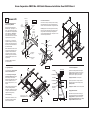
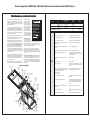
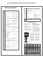
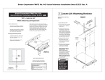
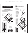
Braun Corporation FMVSS No. 403 Quick Reference Installation Sheet 34274 Rev. A
Braun Corporation FMVSS No. 403
Quick Reference Installation Sheet 34274
1
Locate Lift Mounting Brackets
Rev: A
Locate Lift Mounting Brackets
Alternative
floor structures
are allowed
providing the
installed lift
system passes
all FMVSS 403
requirements.
ACR
OSS
FRA
ME
O
P
E
N
IN
G
E
90
"
3/8
22"
3/8
22-
4. Measure 22-3/8" to left and
right of the center line to
achieve the 44-3/4" center-tocenter spacing of all-thread
mounting studs.
"
3/4
44-
5. Clamp the mounting brackets
securely in place (all-thread
studs must be vertical).
Lift Mounting Brackets
(typical both sides)
Figure A
Mounting Bracket
Requirements:
All four mounting brackets must be
connected to the vehicle chassis
floor members.
B
A
NUVL855RM24
C
Engage Platform Manual
Release System: The lift
cable-activated platform
manual release is disengaged
during shipment to prevent
potential drive chain stretch.
Handle the lift with
care. Engage manual
release before attempting to install
(raise, tilt or move)
the lift.
Door Opening Dimensions:
Vehicle lift access door opening
must meet specified dimensions.
Figure B
TER
ICL
O
Vehicle Floor
Chassis Members
3. Transfer center point to the
vehicle frame. Using a frontto-rear framing member as a
guide, transfer the center point
across chassis to opposite side
front-to-rear framing member
(must be 90° to door opening).
Lift mounting bracket positions
are based on this center line.
IN
ER G
NT NIN
CE OPE
OR
DO
CL
CEN
VEH
O
Vehicle Requirements:
2. Locate center of door opening.
Mark the center point.
D
NHTSA Vehicle Physical Requirements
“DOT - Public Use Lift” verifies this platform lift meets the “public use lift” requirements of FMVSS No. 403.
This lift may be installed on all vehicles appropriate for the size and weight of the lift, but must be installed
on buses, school buses, and multi-purpose passenger vehicles other than motor homes with a gross vehicle weight rating (GVWR) that exceeds 4,536 kg (10,000 lb).
All vehicles with a GVW over 6000 lbs.
and with unmodified OEM framerails.
Figure C
1. Open door(s) fully (min. 90°).
R
“DOT — Public Use Lift”
A
Minimum Clear Door
Opening Height
B
Clear Door Opening Width
43½"
C
Maximum Floor-to-Ground
62½"
NA
WARNING
Engage manual
release before
attempting to install
(raise, tilt or move)
lift. Failure to do so
may result in serious
bodily injury and/or
property damage.
All-Thread
Mounting Studs
Inboard
Left
Right
Outboard
Braun Corporation FMVSS No. 403 Quick Reference Installation Sheet 34274 Rev. A
2
5/16-18 x 1"
Hex Bolt
Secure Lift
1. Attach Mounting Brackets to
Vehicle Framing Members
Position lift mounting brackets as
detailed in Step 1 (see Figures C, D
and F). Oval slotted mounting holes
are provided in the mounting brackets
to allow adjustment. Carefully drill
21/64" (.328") diameter mounting
holes at the center of the oval mounting slots (holes may be present).
Flat
Washer
(typical)
Figure D
All-Thread
Stud
Vehicle
Framing
Members
Twenty 5-16-18 x 1" hex bolts are
supplied for bolting the lift mounting
brackets to the vehicle framing member (four per inboard bracket and six
per outboard bracket).
2. Position and secure lift.
Thread two 3/4" hex jam nuts fully onto each mounting
bracket all-thread stud. Place one large diameter flat
washer onto each all-thread stud. See Figures G and H.
Carefully position lift in vehicle (aligned with mounting
brackets). Position (slide) the six lift mounting clamps
along the sides of the lift housing until aligned with
mounting bracket all-thread studs. See Figure F. Lower
lift onto mounting bracket studs
Jam Nuts
Inboard
Mounting
Bracket
Lift Clamp
Flat Washer
Place a flat washer onto each mounting bolt. Insert bolts through mounting bracket, vehicle floor and framing member as shown in Figure D.
Installation is typical for all brackets
(outboard brackets require 6 mounting bolts each).
Jam Nuts
Lock Washer
(typical)
All-Thread
Stud
Nylock Hex Nut
(typical)
Figure F
All fasteners must meet FMVSS
571.403 Section 6.3.
Figure E
3. Height Adjustment
4. Horizontial Adjustment
C
The lift outer barrier must be aligned
with the vehicle access hole.
The lift housing must be aligned
with vehicle chassis (level). Adjust
the 3/4" hex jam nuts on the allthread mounting studs at all 4 corners
of the lift until dimensions A, B, C
and D are equal (within 1/16"). See
Figure G.
Jam Nuts
Position the lift to achieve a 2” overlap between the deployed inboard
barrier and the vehicle floor.
Shift lift and mounting brackets left-to-right as
needed (lift must be centered in door opening).
Tighten the 5/16" bolts securing mounting
brackets (shown in Figure D) to the frame.
Flat Washer
Lift Clamp
B
Torque Specifications: 20 foot pounds.
Flat Washer
Tighten upper set of 3/4" hex jam nuts (with
flat washer) down to the lift mounting clamps.
Tighten jam nuts.
Jam Nuts
All-Thread
Mounting
Stud
Place one large diameter flat washer
onto each mounting bracket allthread stud. Thread two 3/4" hex jam
nuts fully onto each all-thread stud
(against lift mounting clamp).
In-Out Positioning
Lift Housing
2-1
/2"
Dimensions A, B, C and D
must be equal (within 1/16").
Figure G
Torque Speci cations: 100 to 120 foot pounds.
10¼”
Shipping Block Removal:
D
5-3
Mounting
Bracket
/8"
A
Figure H
Wood blocks are placed in the lift housing to
prevent lift damage during shipment. Remove
shipping blocks from platform and carriage
before running (activating) lift. Refer to Shipping Block Removal Instruction 28942.
Braun Corporation FMVSS No. 403 Quick Reference Installation Sheet 34274 Rev. A
3
Electrical, Hydraulic and Interlock
1/4-20 x 3/4"
Hex Bolts
(Typical)
Note: Locate and drill
hydraulic hose, wiring
harness and manual
release cable access
holes before mounting
pump. A 3" diameter
plastic grommet may be
used (supplied).
mp
Pu ting
un
Mo cket
a
Br
Route hydraulic
hose assembly
through compartment wall to quickdisconnect fitting at
lift. Connect hose.
Note:
Remove
plug from
vent tube.
L
Ca ead
bl
e
s.
we
rC
ab
le
Install Circuit
Sentry as shown
in Figure K. Attach power cable
and lead cable as
detailed.
Ne
g.
Figure K
Connect red positive
(+) power cable here
(from Circuit Sentry).
Vehicle and Lift Interlocks
The pump module is
equipped with a lift interface
9-circuit connector (female
socket). A mating 9-circuit
connector (male plug) is
supplied. To meet minimum NHTSA requirements,
connect to vehicle interlock
harness as outlined in
Figure L (Steps 1-4).
1
Disconnect
and remove
eye terminal
L
To
Following electrical, hyrdaulic
and interlock
installation, check
calibration and
floor level adjustments as defined
in Panel 4.
B
at
.
Po
1
M 2"
ax
.
Check for obstructions
before drilling, cutting holes or installing
mounting hardware.
Remove the plug
from 1/4" diameter
clear vent tube.
See Figure L.
Calibration and
Floor Level
Adjustment
Po
1/
8"
Pl x 4"
as x
tic 4
"
Figure I
Circuit Sentry:
Ci
Se rcu
nt it
ry
Hydraulics:
Mount the pump module
case to the inner wall
of the adjacent storage
compartment as shown
in Figure I.
A
ux
.
3/8"-16 x 1" Hex Bolts with Flat
Washer and Nylock® Hex Nuts
Pump Module Mounting
ift
Adjacent
Compartment
Wall
2
Pump Ground Cable:
Vehicle Battery Ground Cable:
One ground cable is pump mounted. Connect cable to a vehicle
framing member (see Figure J).
A ground cable (minimum 2 gauge)
must be connected from vehicle
battery negative post to the same
vehicle framing member the pump
ground cable is attached to.
5/16"
External Tooth
Star Washer
9/32"
Diameter
Pilot Hole
is
ass
Ch
Figure J
Ground Cable Mounting
Thread
Cutting
Screw
Ground Cable Corrosion:
When mounting ground
cables, remove undercoating, dirt, rust, etc. from
framing member around
mounting holes. Apply
protective coating to mounting holes to prevent corrosion. Failure to do so will
void warranty of certain
electrical components.
Note: All
wiring harness
connections
must be inside the pump
module box.
g
i rin
t W es
Lif ness
n
i
Ma Har
tor
era
Op
or
o
sed
ID
Clo
MC
ull
IF
C
M
t1
Ma
h
old
t2
hts
rm
g
sh
Ma Switc Lig
e
r
Ala
d
i rin
l
m
Th
er
be
ho
for
t W ses
tro
s
res Pow Plat
Lif
S
h
in arne
T
a
M
H
Housing/Carriage
Harnesses:
Route two main wiring harnesses from
lift to pump module.
Connect to mating
harnesses at pump.
Beeper/Strobe
Alarm and Platform Lights:
Connect harnesses to mating
harnesses at
pump module.
Connect vehicle
interlock signal wires
l
na
re
cu
e
le S
Sig
ic
h
Ve
cl e
I nt
e rl
ock
Figure L
To
J
Threshold Warning Sensor:
Connect both threshold sensor mat harnesses to mating
Y-harness at pump module
(labeled). Both mats must
be installed on a flat rigid
surface.
To
Veh
i
Inboard edge of inboard
mat must be minimum 18"
from edge of finished floor
or stepwell.
um
per
# 31
730
A
Braun Corporation FMVSS No. 403 Quick Reference Installation Sheet 34274 Rev. A
4
5
Calibration and Floor Level Adjustment
FMVSS 403/404 Certification Checklist
NUVL855RM24 Control Board
Lift_Out
A
C
B
DOT — Public Use Lift
D
R55
LCD MODULE
J37
K
L
Y2
J
I
H
G
8.00M
J29
J30
R58
5
10
R41
DIAG
C8
3
8
C13
100
VHA
R21
R48
R46
R44
R37
R31
Threshold
Area
U10
3
U5
2
8.00M
R47
R45
R30
C2
D5
R36
R32
R33
D4
C6
R34
J13
SW_1
D3
R75
R76
U20
R35
J40
C18
R26
D2
FL_CL
220
CFK
R29
R72
J27
U11
50# CAL
SW_0
R64
MP916
0.010Ω
.5% R
Bit_1
R70
U?
D14
R62
Bit_0
C14
HI
O_BAR
R78
L_OUT
Y2
MAG_SW
R51
5
6
L_IN
100
VHA
C12
U15
J4
SVC LIGHT
4
7
J 23
J25
R69
R49
R40
B_UP
B_DN
2
9
J 24
R39
C4
C5
HAND-1
L_DN
1
1
C10
R27
Platform
Lighting
R77
R42
R53
R61
R68
L_UP
2
2
D/S
3
CYCLE
R52
R60
J22
HAND-2
Public use vehicle manufacturers
are responsible for complying with
the lift lighting requirements in Federal Motor Vehicle Safety Standard
No. 404, Platform Lift Installation in
Motor Vehicles (49 CFR 571.404).
100419-001 REV
R57
3
C11
INT
2
4
C17
K10
1
K7
3
RL11
RL11
LO
J39
J6
J36
J32
J47
4
Ground Sense Calibration
1. Press hand-held pendant DOWN switch to lower platform fully to
ground level.
2. While continuing to press the pendant DOWN switch, press and
then release the control board O_BAR GND. button.
3. Release the pendant DOWN switch.Ground level sensing is now
calibrated.
Visual and Audible
Threshold Warning
Floor_SW
R54
U/D
Platform Sense Calibration
1. There must be no weight on platform.
2. Press hand-held pendant UP switch to raise platform a minimum
3" above stow level.
3. Press and hold control board 50# CAL. button. While pressing
the 50# CAL. button, press and hold the hand-held pendant
STOW switch (button). The platform will lower to stow level
(begin stow function), and then start to raise. Release 50#
CAL. button immediately when platform starts to raise from stow
level.
4. After calibration, the LCD screen should read “PF OCCUPIED”
whenever there is 50 lbs. or more present on the platform. The
50 pound platform sensing is now calibrated.
J38
3
MAT
3
J45
2
2
1
1
J9
GND
D17
J11
PWR
J10
D16
J8
J35
D11
D12
U2
D13
C23
220
35A
R32
1001
R34
1001
C18
L - IN
PUMP
L - OUT
B - DN
VALVE
D9
B - UP
D6
1001
R33
1001
R35
1001
J4
FL_CL
U11
50# CAL
R26
2400
R29
2051
J17
J16
220
35A
J21
ALARM
LIGHTS
Inner
Roll Stop
D10
D7
D8
J5
J19
J20
Outer Barrier Occupied Calibration
1. Press hand-held pendant DOWN switch to lower platform fully to
ground level.
2. Once outer barrier is fully unfolded (ramp position), release the
pendant DOWN switch.
3. Press and hold the control board O_BAR GND. button. While
holding O_BAR GND. button, press hand-held pendant UP
switch to raise the outer barrier. Be sure to release O_BAR
GND. button when outer barrier reaches approximately half full
up (vertical) position.
4. After calibration, the LCD screen should read “OUT-BAR OCCUPIED” whenever there is weight present on the outer barrier.
J14
C19
J15
Bit_1
6C9
220
CFK
Bit_0
Dual
Outer Barrier
V104
O_BAR
C17
K10
K7
Platform
RL1
50# CAL
Button
O_BAR GROUND
LVL Button
Floor Level Switch
The Floor Level switch stops upward travel of the platform
during the Up function (activated by the torque tube-mounted
Floor Level cam). Position the lift platform 1" above floor
level using the manual operation system (detailed on
opposite side of this sheet). Loosen the clamp securing the
torque tube-mounted Floor Level cam. Rotate the cam until
the Floor Level switch is activated (cam depresses switch).
The operations listed below must be functionally verified.
Floor Level Cam
Floor Level Switch
Vehicle movement is prevented unless the lift door
is closed, ensuring the lift is stowed.
Lift operation shall be prevented unless the
vehicle is stopped and vehicle movement is
prevented.
Note: Check the floor level position of the platform and the
inner roll stop after powering the pump. Hydraulic pressure
may affect platform height slightly. Fine tuning adjustment
(tweaking) of the Floor Level switch may be required.
The inner roll stop must rest properly on the vehicle floor
when the lift is deployed. Adjust the inner roll stop only if
necessary (refer to the service manual).
The platform will not fold/stow if occupied.
The inner roll stop will not raise if occupied.
Verify platform lighting when lift is deployed and
pendant illumination when lift is powered.
Torque Tube
The outer barrier will not raise if occupied.
A visual and audible warning will activate if the
threshold area is occupied when the platform is at
least one inch below floor level.
Platform movement is prohibited beyond the position where the inner roll stop is fully deployed (up).
Lift platform movement shall be interrupted unless
the outer barrier is deployed (up).
Cam depressing switch.
34274 Rev. A
Braun Corporation FMVSS No. 403 Quick Reference Installation Sheet 34274 Rev. A
Lift Operating Instructions
4. Press the DOWN switch until the
entire platform reaches ground
level and both outer barriers
unfold fully (ramp position).
Release switch. See Photo G.
I
In the event of power failure, refer to the Manual Operating Instructions to operate the lift.
J
Hand-held Pendant Control:
5. Unlatch handrail belt, unlock
wheelchair brakes and unload
passenger from platform.
STOW
The hand-held attendent's pendant
control is equipped with three push
button switches (STOW, DOWN
and UP). The momentary switches
activate the automatic lift functions.
Simply press the switch labeled for
the intended function. When there is
power to the lift, the lift function labels
illuminate to identify the functions.
STOW
DOWN
DOWN
UP
UP
K
Note: Outer barriers must be
fully unfolded (ramp position)
until the entire wheelchair (or
standee has crossed both outer
barriers. See Photos I and J.
L
TO LOAD PASSENGER:
TO DEPLOY PLATFORM:
A
B
1. Read Notes below! Load
passenger onto platform, lock
wheelchair brakes and latch
handrail belt.
1. Stand Clear and press the UP
switch until the platform stops
(extends fully). Release Switch.
2. Lift handrail latch handles,
deploy handrails up to vertical
position and lower latch handles
fully. See Handrail Operating
Instructions.
Lift stops just below door.
C
OPEN - DOOR - CLOSE
Inner Roll Stop
Note: Outer barriers must be
fully unfolded (ramp position)
until the entire wheelchair (or
standee) has crossed both outer
barriers. See Photos I and J.
M
Inner Roll Stop at Floor Level
3. Lift outer barrier to vertical position. See Handrail Operating
Instructions. See Photo B.
Note: Passenger must be
positioned fully inside yellow
boundaries.
D
2. Press the UP switch to fold both
outer barriers up fully (vertical)
and raise the platform until the
platform stops. Release switch.
4. Latch the handrail belt (see
Photo B).
5. Press the UP switch until the
platform stops (just below the
door opening). Release switch.
E
6. Open bus door fully.
Note: Platform will stop just
below the door opening.
F
Inner Roll Stop at Floor Level
O
7. Press the UP switch until the
platform stops (raises to floor
level) and the inner roll stop unfolds fully to floor level position.
Release switch. See Photo D.
5. Unlock wheelchair brakes and
unload passenger from platform.
1. Read Note below! Load passenger onto platform and lock
wheelchair brakes.
Note: Passenger must be
positioned fully inside yellow
boundaries and outer barrier
must be UP.
2. Press DOWN switch until platform stops (just below the door
opening - as shown in Photo G).
Release switch.
3. Close bus door fully.
P
3. Open bus door fully. See Photo
N.
4. Press the UP switch until the
platform stops (raises to floor
level) and the inner roll stop unfolds fully to floor level position.
Release switch.
TO UNLOAD PASSENGER:
G
N
H
TO STOW PLATFORM:
1. Latch handrail belt. See Photo B.
2. Press the STOW switch until platform stops at stow level. Release switch.
3. Unlatch handrail belt.
4. Fold tall outer barrier down to platform (horizontial) position.
5. Lift handrail latch handles, stow handrails down to platform
(horizontial) position and lower latch handles fully.
6. Press the STOW switch until the platform stops (retracts fully).
Q
Braun Corporation FMVSS No. 403 Quick Reference Installation Sheet 34274 Rev. A
Handrail Operating Instructions
OUT (TO EXTEND PLATFORM):
2. a. Lift latch handle.
b. Deploy / Stow handrail.
c. Lower latch handle.
3. a. Lift latch handle.
b. Deploy / Stow handrail.
c. Lower latch handle.
a.
Pull T-Handle.
Turn T-Handle to lock platform in released position.
Pull platform out.
Turn T-Handle.
Push T-Handle in.
Grasp outer barrier and attempt to move platform in and out
until the platform locks (feel release mechanism engage).
WAR
NING
Do
not
rem
ove!
VALVE
OSE
CL
c.
Latch
Handle
Detail
b.
1.
2.
3.
4.
5.
6.
OPEN
1. Fold tall (yellow) outer barrier
down.
DOWN (TO LOWER PLATFORM):
Using hand pump handle, open hand pump valve (turn counterclockwise). Open 1/2 turn only.
b.
c.
a.
CLOSE
DOWN (TO UNFOLD OUTER BARRIER):
1. Remove hairpin cotter from detent pin.
2. Remove detent pin.
3. Unfold (rotate) barrier down.
Latch
Handle
Detail
Ac
Ha
irp
Co in
tter
tua
tor
t
ten
De
Pin
O
R
M
UP (TO FOLD OUTER BARRIER):
T-Handle
Release
Cable
Pump
Handle
POWER
PACK
Valve
After manually moving the platform
in or out, it is extremely important
that the cable-activated manual
release is positively re-engaged to
secure (lock) the platform carriage
assembly before loading a passenger on the platform or before driving
the vehicle.
After manually releasing platform,
push manual release T-handle
in fully and ensure platform is
locked before driving lift vehicle.
Uncontrolled and unintentional platform deployment (inadvertent platform ejection) may
result in serious bodily injury
and/or property damage.
B
A
R
R
IE
R
UP (TO RAISE PLATFORM):
VALVE
Using hand pump handle:
1. Close hand pump valve (turn clockwise).
2. Insert handle in pump and stroke.
OSE
CL
Hand
Pump
Cable Activated Platform Manual
Release System: A cable-activated
manual release system releases
and engages the platform carriage
assembly drive chain to allow the
platform carriage assembly to be
manually moved out (extended) or
moved in (retracted) as needed. A
T-handle is provided on the release
cable for activation of the manual
release system (details follow).
OPEN
Manual Operating Instructions
Familiarize yourself with the components necessary to manually
operate the lift. The T-handle
release cable releases and engages the lift platform to allow the
platform to be manually extended
and retracted. The manual backup pump (hand pump) is used to
manually lower and raise the extended platform.
O
U
TE
R
1. Fold (rotate) barrier up.
2. Insert detent pin.
3. Insert hairpin cotter in detent pin.
PL
AT
F
Note: Order of procedures
shown is for stowing lift. To
deploy handrails and barrier
after extending the platform,
reverse order of procedures.
OPEN
Note: Close valve before operating electric pump.
WARNING
Push T-handle in fully and
manually move platform in
and out to engage platform
lock before driving vehicle.
Failure to lock platform may
result in unintended platform
deployment. Unintended
platform deployment may
result in serious bodily injury
and/or property damage.
IN (TO STOW PLATFORM):
1. Raise or lower platform to stow level (follow UP or DOWN
procedures).
2. Pull T-Handle.
3. Turn T-Handle to lock platform in released position.
4. Push platform in.
5. Turn T-Handle.
6. Push T-Handle in.
7. Grasp outer barrier and attempt to move platform in and out
until the platform locks (feel release mechanism engage).
WAR
NING
Do
not
rem
ove!
Braun Corporation FMVSS No. 403 Quick Reference Installation Sheet 34274 Rev. A
Maintenance and Lubrication
Proper maintenance is necessary to ensure safe, troublefree operation. Inspecting the lift for any wear, damage
or other abnormal conditions should be a part of all transit
agencies’s daily service program. Simple inspections can
detect potential problems.
The maintenance and lubrication procedures speci ed in
the following schedule must be performed by a Braun authorized service representative at the scheduled intervals
according to the number of cycles. NHTSA NUVL Series
lifts are equipped with a cycle counter (digital display built
into the electronic control board).
NUVL Series lifts are equipped with hardened pins and
self-lubricating bushings to decrease wear, provide smooth
operation and extend the service life of the lift.
When servicing the lift at the recommended intervals,
inspection and lubrication procedures speci ed in the previous sections should be repeated. Clean the components
and the surrounding area before applying lubricants.
LPS2 General Purpose Penetrating Oil is recommended
where Light Oil is called out. Use of improper lubricants
can attract dirt or other contaminants which could result in
wear or damage to the components. Platform components
exposed to contaminants when lowered to the ground may
require extra attention.
Lift components requiring grease are lubricated during assembly procedures. When replacing these components,
be sure to apply grease during installation procedures.
Speci ed lubricants are available from The Braun Corporation (part numbers below).
All listed inspection, lubrication and maintenance procedures should be repeated at “750 cycle” intervals following
Drive Chain and Rollers
LO
the scheduled “4500 Cycles” maintenance. These
intervals are a general
guideline for scheduling
maintenance procedures
and will vary according to
lift use and conditions. Lifts
exposed to severe conditions (weather, environment, contamination, heavy
usage, etc.) may require
inspection and maintenance
procedures to be performed
more often than speci ed.
WARNING
Maintenance and lubrication procedures
must be performed
as speci ed by an
authorized service
technician.
Failure to do so may
result in serious
bodily injury and/or
property damage.
Lubricant
LO - Light Oil
DE - Door-Ease
SG - Synthetic Grease
Maintenance Indicator:
A Lift Ready green LED is
mounted on the hand-held
pendant storage bracket. The green LED will change color to
yellow after every 750 cycles. The yellow LED will not affect
the functions of the lift, but is a reminder to perform necessary
maintenance and lubrication procedures.
Once the lift has been serviced, press the CYCLE button
(located below LCD display on the control board) until the Lift
Ready LED changes back to green. The CYCLE button also
clears the lift cycle count (since last service) but not the lifetime
cycle count.
Discontinue lift use immediately if maintenance and lubrication procedures are not properly performed, or if there is any
sign of wear, damage or improper operation. Contact your
sales representative or call The Braun Corporation at 1-800THE LIFT®. One of our national Product Support representatives will direct you to an authorized service technician who will
inspect your lift.
Type
750
Cycles
Speci ed (recommended)
Lubricant
Light Penetrating Oil
LPS2, General Purpose
(30 weight or equivalent)
Penetrating Oil
Stainless Stick
Door-Ease
Style (tube)
Stick (tube)
Synthetic Grease
Mobiltemp SHC32
(Multipurpose)
Hydraulic
Cylinder
Pivot
Points
LO
Hydraulic
Cylinder
Pivot
Points
LO
Eccentric
Shaft
Rollers
(bearings)
LO
Platform Cable-activated
Manual Release System
Torque Tube
Pivot Points
LO
Lifting Arm
Pivot Points
LO
Rolling
Horizontial
Carriage Tube
Slot Area
DE
Eccentric
Shaft and
Carriage
Rollers
(bearings)
LO
Torque Tube
Pivot Points
LO
Outer
Barrier (tall)
Pivot Points
LO
Outer Barrier
Detent Pin
LO
Lifting Arm
Pivot Points
LO
Inner Roll Stop
Linkage
Pivot Points
LO
Inner Roll Stop
Hinge
Pivot Points
and
Eccentric
Inner Roll
Shaft and
Stop Catch
Carriage
LO
Rollers
(bearings)
LO
Outer Barrier (short)
and
Lower Closure
Pivot Points
LO
11 oz.
Aerosol Can
1.68 oz.
12.5 oz.
Tube
Braun
Part No.
15807
15806
28598
Outer barrier and lower closure pivot points (2)
Apply Light Oil - See Lubrication Diagram
Outer barrier detent pin pivot points (2)
Apply Light Oil - See Lubrication Diagram
Inner roll stop hinge pivot points
Apply Light Oil - See Lubrication Diagram
Inner roll stop linkage pivot points
Apply Light Oil - See Lubrication Diagram
Lifting arm center and platform pivot points (bearings at all points)
Apply Light Oil - See Lubrication Diagram
Inspect outer barrier and lower closure for proper
operation
Correct or replace damaged parts.
Inspect outer barrier seal and lower closure gasket
Resecure, replace or correct as needed
Inspect outer barrier detent pin hairpin cotter
Ensure hairrpin cotter is present and can be
removed and inserted easily. Resecure, replace
or correct as needed.
Inspect lift for wear, damage or any abnormal
condition
Correct as needed.
Inspect lift for rattles
Correct as needed.
Check drive chain tension.
Pull out and lock manual release cable. Adjust
chain tension as needed. See Drive Chain Adjustment.
Inspect inner roll stop (bridge plate) and linkage for:
• Proper operation. Roll stop should rest solidly on
oor providing smooth transition.
• Positive securement
• Wear or damage
Resecure, replace or correct as needed. See
Inner Roll Stop Adjustment Instructions.
Check carriage ride height in housing
Adjust as needed. See Carriage Ride Height
Adjustment.
Check stow height/lifting arm alignment
Lifting arms should be horizontal, aligned with
each other and aligned with carriage. Adjust as
needed. See Switch Adjustment (Below Stow
Switch).
Inspect wiring harnesses for securement, wear or
other damage
Resecure, replace or correct as needed
Check lower pan securement
Resecure, replace damaged parts or correct as
needed.
Torque tube pivot bearings (4 places)
Apply Light Oil - See Lubrication Diagram
Lubrication Diagram
Drive Chain
Release Latch
SG
Available
Amount
Braun Corporation FMVSS No. 403 Quick Reference Installation Sheet 34274 Rev. A
Maintenance and Lubrication
Use 5606 aviation uid only (part 87010R-MILL).
Check uid level with platform lowered fully.
Fill to within 1-1/2" of the bottom of the ll tube
(neck).
Inspect lifting arm bushings and pivot pins for visible wear or damage
Replace if needed.
Inspect outer barrier pivot pin mounting bolts (2)
Tighten or replace if needed
Mounting
Check to see that the lift is securely anchored to
the vehicle and there are no loose bolts, broken
welds, or stress fractures.
Decals and Antiskid
Replace decals if worn, missing or illegible.
Replace antiskid if worn or missing.
Carriage and eccentric shaft rollers (bearings)
Apply Light Oil - See Lubrication Diagram
Lifting arm slots in rolling horizontial carriage arm
tubes
Apply Door Ease - See Lubrication Diagram. Apply to the surface area around both slots and wipe
off excess
Hydraulic cylinder pivot points (4 per cylinder)
Apply Light Oil - See Lubrication Diagram
Drive chain and chain rollers
Apply Light Oil - See Lubrication Diagram
Drive chain release latch mechanism
Apply Synthetic Grease - See Lubrication Diagram
Deploy lift, remove inboard and outboard lower
pans and blow out housing. Blow off platform also.
Use compressor and nozzle to remove all debris
from housing. Clean outboard lower pan slot and
apply Antisieze to slot before reinstalling pan.
Deploy lift, remove inboard and outboard lower
pans and clean housing tracks
Use clean cloth and solvent to clean tracks. Clean
lower pan slot and apply Antisieze to slot before
reinstalling pan.
Check drive chain tensioner, jam nuts and connecting link for securement and/or misalignment.
Correct or replace damaged parts and/or relubricate. See Drive Chain Adjustment.
Inspect drive chain release latch mechanism for
proper operation, positive securement, wear or
other damage
Correct or replace damaged parts and/or relubricate.
Inspect platform cable-activated manual release
system (T-handle/cable assembly and carriage
movement)
Ensure T-handle release and cable assembly
operate properly (see Manual Operation). Ensure
carriage can be manually extended and retracted
freely.
Inspect limit switches for securement and proper
adjustment
Resecure, replace or adjust as needed. See
Switch Adjustment.
Inspect carriage, lifting arm and eccentric shaft
rollers (bearings) for wear or damage, positive
securement and proper operation
Correct, replace damaged parts and/or relubricate.
Inspect external snap rings (e-clips):
• Carriage roller bearings (4)
• Lower lifting arm pins (5)
• Upper lifting arm pins (2)
• Outer race bearings (2)
• Inner roll stop shaft (2)
Resecure, replace or correct as needed.
Inspect lower lifting arm pins for wear or damage,
positive securement and proper adjustment
Resecure, replace damaged parts, lubricate or
correct as needed.
Inspect eccentric shaft pins, bearing mounting
screw, washers and securement hardware for
wear or damage, positive securement and proper
operation
Resecure, replace damaged parts, lubricate or
correct as needed. See Carriage Ride Height
Adjustment.
Inspect torque tube cams for securement, wear or
damage
Resecure, replace or correct as needed.
Inspect housing cam brackets for securement,
wear or damage
Resecure, replace or correct as needed.
LCD Display Stowed Moving Out
Of Cassette
Inspect cylinder(s), hoses, ttings and hydraulic
connections for wear, damage or leaks
Tighten, repair or replace if needed.
STOW SW
Inspect power cable
Resecure, repair or replace if needed.
4500
Cycles
Consecutive Repeat all previously listed inspection, lubrica750 Cycle tion and maintenance procedures at 750 cycle
intervals.
Intervals
Adjustments and Diagnostics
Drive Chain Adjustment
In event the drive chain sags 1/2" or more, adjust tension
as detailed.
Tighten to eliminate visible sag but do not overtighten.
1. Remove bottom pan.
2. Pull the manual release cable and lock.
3. Remove adjustment bolt (tensioner) access cover.
4. Loosen inside jam nut. Secure tensioner and tighten
outside jam nut. Tighten to eliminate visible chain sag but
do not overtighten.
5. Lock jam nuts together making sure the tensioner roller is
horizontial. Release and push the manual cable in fully.
Ensure platform is locked by moving the platform in and
out until chain release assembly engages chain.
D8
D5
D6
D3
D2
102
102
D4
R31
C
cycle
Carriage Ride Height Adjustment
The carriage horizontal arms move (roll) in and out of the
housing tracks on roller bearings. Following installation or
extensive lift operation, clearance between horizontal arms
and tracks may diminish. The eccentric shaft mounting
plate allows height adjustment.
Remove eccentric plate mounting screw. Using screwdriver or small rod, rotate the shaft clockwise to increase
carriage height. Rotate the shaft counterclockwise to decrease carriage height. Reinstall mounting screw in nearest retainer hole. Adjust left and right side eccentric shafts
(screw positions may vary from side to side). Adjust height
such that horizontal arms do not contact top or bottom of
tracks (align center). For Calibration procedures and Floor
Level Adjustment, see Panel 4 on reverse side.
Diagnostics: Following installation,
verify all lift functions and ensure that
the control board correctly registers
the values listed below when the
corresponding action is taken. “1”
will appear on the LCD screen as
shown in the Illustration at right. If
any other value appears on the LCD
screen during the speci c diagnostic
procedure, verify that the correct harness is properly connected to both
the control board and the associated
lift harness. Repeat the harness
D7
V104 C6
S T LV S W 1
102
1500
Cycles
Hydraulic Fluid (Pump) - Check level. Note: Fluid
should be changed if there is visible contamination. Inspect the hydraulic system (cylinder, hoses,
ttings, seals, etc.) for leaks if uid level is low.
S T LV S W 1
diagnostic procedure. If an incorrect
value is still present after checking the
harness and connections, contact The
Braun Corporation Product Support
Department at 1-800-THE-LIFT®.
All basic functions (UP, DOWN, DOOR
and STOW) should show a value of 1
when activated via a controlled input
(Hand-held Pendant, Magnetic, Remote Entry or 3rd Station Controls).
Refer to the service manual for additional switch and sensor information.
Pump Module
Control Board
Full Out Moving At Floor Moving Down
Up
Level
STLV SW
1
1
1
1
Ground Level
OB Out
1
FOUT SW
1
FLV SW
OBAR SW
Ground Level
1
1
1
1
1
1
1
1
1
1
SBELT SW
= 1 When Seat Belt is Plugged In.
MAT SW
= 1 When Mat is Activated
IBAR SW
= 1 When IN Barrier is activated
DO SW
= 1 When Door is Full Open. Or pin 3 and pin 4 are jumpered.
LO VOLT
1