1
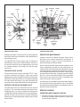
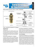
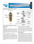
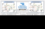
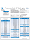
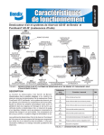
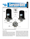
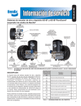
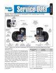
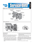
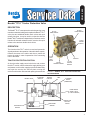
SD-03-3655
®
Bendix® TP-5™ Tractor Protection Valve
DESCRIPTION
The Bendix® TP-5™ tractor protection valve is a panel or cross
member mounted unit designed to replace the Bendix® TP-3®
valve plus two additional double check valves and quick
release functions. It may be used in conjunction with the
Bendix® MV-3® module or independently. It contains a service
line shut-off valve with exhaust function, a service line quick
release valve and two double check valves.
3/8" NPT
FRONT SERVICE
3/8" PTC
REAR SERVICE
1/2" NPT
TRAILER
SUPPLY
OPERATION
The function of the TP-5™ valve is to receive all pneumatic
signals pertinent to the operation of the trailer brake system,
transmit the same to the trailer and also to protect the
tractor air supply in case of separation of the connecting
lines to the trailer.
TRACTOR PROTECTION PORTION
Air from the trailer supply control valve in the cab, such as
the MV-3® module, enters at the trailer supply delivery port
and passes out the trailer supply port and simultaneously
acts upon the service line shut-off piston moving the
service line inlet valve off its seat and opening the service line
FROM TC VALVE
TO TRAILER
SERVICE
1/4" PTC
STOP
LIGHT
SWITCH
EXHAUST
3/8" NPT
TRAILER CONTROL
FIGURE 1 - BENDIX® TP-5™ TRACTOR PROTECTION
VALVE EXTERIOR
SERVICE
LINE QRV
VENT
TO TRAILER
SUPPLY
(EMERGENCY)
FROM TRAILER
SUPPLY VALVE
(E.G. MV-3® MODULE)
STOP LIGHT
SWITCH
FROM REAR
SERVICE
1/2" NPT
TRAILER
SERVICE
FROM FRONT
SERVICE
SERVICE LINE
SHUT-OFF
PISTON
FIGURE 2 - BENDIX® TP-5™ TRACTOR PROTECTION VALVE SCHEMATIC DIAGRAM
1
O-RING
(3)
INSERT
(9)
O-RING
(4)
O-RING
(7)
CAP
NUT
(13)
RETAINING
RING
(15)
SPRING
(16)
O-RING
(6)
VALVE
(2)
O-RING
(5)
DIAPHRAGM
(1)
O-RING
(5)
O-RING
(7)
CAP
NUT
(10)
EXHAUST
CHECK
VALVE
DIAPHRAGM
(8)
O-RING
(7)
#6
TORX/
PN
SCREW
(17)
CAP NUT
(12)
COVER
(18)
O-RING
(4)
CAP
NUT
(11)
DOUBLE
CHECK
SHUTTLE
(9)
DOUBLE
CHECK
GUIDES
(14)
SERVICE LINE
SHUT-OFF
PISTON
(19)
FIGURE 3 - BENDIX® TP-5™ TRACTOR PROTECTION VALVE
END SECTIONAL VIEW
FIGURE 4 - BENDIX® TP-5™ TRACTOR PROTECTION VALVE
SIDE SECTIONAL VIEW
passage (see Figure 2). With common air to the supply side
and service side of the manifold the valve should open at
approximately 45 psi.
PREVENTIVE MAINTENANCE
If the Bendix® MV-3® tractor supply valve is manually or
automatically moved to the exhaust position, the service
line shut-off valve will close at approximately 10 psi and
the exhaust passage in the plunger will vent the trailer
service line.
DOUBLE CHECK VALVES
The two double check valves in the Bendix® TP-5™ valve,
as seen in schematic view Figure 2, serve to pick up the
highest pressure service signal from either the tractor front
brake circuit, rear brake circuit or TC valve signal, operating
the trailer brakes accordingly. The stop light switch port
also picks up this signal and actuates the stop light switch.
SERVICE LINE QUICK RELEASE VALVE
The trailer service line port is located in the cover, as seen
in Figure 3. This cover also houses a quick release valve.
Diaphragm (Item 1 in Figure 3) seals off the exhaust port
on application and upon release of service line application,
permits the trailer service line air to exhaust through the
exhaust port, thus permitting faster release times for trailer
brake release.
2
Important: Review the Bendix Warranty Policy before
performing any intrusive maintenance procedures. A
warranty may be voided if intrusive maintenance is
performed during the warranty period.
No two vehicles operate under identical conditions; as a
result, maintenance intervals may vary. Experience is a
valuable guide in determining the best maintenance interval
for air brake system components. At a minimum, the TP-5™
valve should be inspected every 6 months or 1500 operating
hours, whichever comes first, for proper operation. Should
the TP-5™ valve not meet the elements of the operational
tests noted in this document, further investigation and
service of the valve may be required.
A maintenance kit is available under part number 289061.
For the latest service parts and kits, refer to the Bendix
Quick Reference Catalog (BW1114) available for order or
download at www.bendix.com.
SERVICE CHECKS
OPERATING AND LEAKAGE CHECKS
1. Charge the air brake system to governor cut-out, block
the wheels, and place tractor protection control valve
in the emergency position.
2. Disconnect the trailer service line hose coupling. Make
a trailer hand control valve application. Cover the 1/16
inch vent hole in the service line shut-off valve area of
the Bendix® TP-5™ valve body. Check for leakage at
hose coupling and at exhaust port at the TP-5™ valve.
Excessive leakage at either port indicates a faulty inlet
valve, item 2 on Figure 4.
3. With the hand control valve still applied, turn the ignition
on and check for the stop light function.
4. Release the hand control valve application and place
the tractor protection valve in the normal position.
5. Connect the tractor service hose coupling to a test
gauge, re-apply the hand control valve and note that
there is pressure at the service hose coupling.
6. Check for leakage at the service line quick release
valve. Excessive leakage would indicate a defective
diaphragm (1). See Figure 3.
7. With the service line pressure still applied through the
hand control valve, check for leakage at the brake valve
exhaust. Excessive leakage indicates a defective
double check valve shuttle.
8. Check for leakage at the 1/16 inch vent hole. Leakage
indicates either o-ring (6) or o-ring (5) on the service
line shut-off piston (19) is defective. Note the same size
o-ring is identified as (5) is also used on cap nut (10).
9. Release the hand control valve application and re-check
for leakage at the vent hole. If the leakage continues,
the large o-ring (5) is the cause for the leak and if the
leakage stops, the smaller o-ring (6) is the cause of the
leak.
10. Make and hold a foot brake application. Check for
leakage at exhaust of hand control valve. Excessive
leakage indicates a faulty double check valve shuttle.
3
11. Release the foot brake application, disconnect the line
from primary service brake circuit at Bendix® TP-5™
valve delivery port (PCD) and block off the end of the
line from the brake valve. Make a foot brake application
and observe for leakage at the PCD delivery port.
12. Reconnect the primary circuit line and reverse the
procedure with the secondary circuit line (SCD).
Excessive leakage in either (11) or (12) indicates a faulty
double check valve shuttle. Restore the secondary circuit
connection to the TP-5™ valve.
If the valve does not function as described above, or
leakage is excessive, the valve should be exchanged or
replaced at the nearest authorized Bendix Parts distributor.
If this is not possible the following should prove helpful.
DISASSEMBLY
1. Block the wheels and drain the air brake systems.
2. Remove all air lines and the stop light switch from the
manifold and remove the unit from the vehicle.
3. Remove the four cap nuts, (items 10, 11, 12, and 13)
from the body. Identify the cap nuts to their respective
ports before removing. Remove the o-ring (3 of item 7
and one of item 5). See Figure 4.
4. Remove the double check guides (14) and double check
shuttles (9).
5. Reach into the port marked BLK-SLS with a set of snap
ring pliers and remove the snap ring (15), spring (16),
and valve (2).
6. Remove the two screws which hold the cover (18)
to the body. Remove the two small o-rings (4) and
one large o-ring (3). Remove the quick release valve
diaphragm (1). See Figure 3.
7. Remove the 6-32 pan head screw (17) and remove the
exhaust check valve diaphragm (8).
CLEANING AND INSPECTION
1. Clean all metal parts in mineral spirits and dry them
completely.
2. Inspect all parts for excessive wear or deterioration.
Inspect valve seats for nicks or burrs. Check the valve
spring for cracks or corrosion.
3. Inspect the bores of the valve housing for deep scuffing
or gouges.
Replace all parts that were discarded and any parts not
found to be serviceable during inspection, using only
genuine Bendix replacement parts.
ASSEMBLY
Before assembling the TP-5™ valve, lubricate all o-rings,
o-ring grooves, body bores and rubbing surfaces with
Bendix silicone lubricant (Pc. No. 291126) or equivalent.
NOTE: When using pipe thread sealant during assembly
and installation, take particular care to prevent the
sealant from entering the valve itself. Apply the
sealant beginning with the second thread back
from the end.
1. Re-install inlet valve (2), spring (16) and lock ring (15)
in body. See Figure 4.
2. Install shuttle guides (14) and shuttles (9) and their
respective cap nuts (10) and (11).
3. Install the o-rings (5) and (6) on the service line shutoff plunger (19), and install spring (20), plunger and
corresponding cap nut (12) with o-ring (7).
4. Position the quick release valve diaphragm in the body
(18) and the o-rings (3) and (4) on the cover and install
the cover in its cavity in the body. See Figure 3.
5. Replace the exhaust seal diaphragm (8) in the cover.
TESTING
Test the re-assembled valve per Operating and Leakage
Checks.
4
BW1575 © 2011 Bendix Commercial Vehicle Systems LLC • 5/2011• All rights reserved.