1
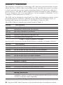
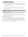
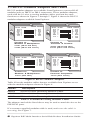
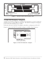
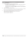
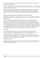
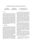
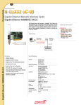
SuperSerial™ ESP Multi-Interface Serial Hub Product Installation Guide PN 590-290-001A August 2002 Section 1 - Hardware The Equinox SuperSerial Technology (ST) Ethernet Serial Provider 8-port Multi-Interface (ESP-8 MI) Serial Hub can be installed in a local or remote LAN to provide access for widely distributed RS-232, RS-422 or RS-485 serial devices. The ESP-8 MI is supported under Windows 2000, Windows NT 4.0, Windows NT 3.51, OpenServer 5.0.5a or higher, UnixWare 7.0.1a or higher, Linux and AIX 4.3 and 5.1. The ESP can be managed using EquiView Plus, the Equinox premier serial port management software, running on any Microsoft Windows host, or espdiag and espcfg for OpenServer, UnixWare, Linux or AIX. The ESP-8 MI kit contains the items listed in Table 1. Part No. Description 990407 8-port ESP-8 MI Unit 590 Installation Guide (this document) 750131 RS-422 Loopback Connector 750130 RS-232 Loopback Connector 650185 Equinox SuperSerial Software CD 770379 Two Wall-mount Brackets Table 1. ESP-8 MI Kit Contents Special-order accessories for the ESP-8 MI are available, as listed in Table 2. Part No. Description Modular Adaptors 210097 RJ-45 to DB-25 RS-232 DTE Male Adaptor 210098 RJ-45 to DB-25 RS-232 DTE Female Adaptor 210099 RJ-45 to DB-25 RS-232 DCE Male Adaptor 210100 RJ-45 to DB-25 RS-232 DCE Female Adaptor 210101 RJ-45 to DB-9 RS-232 Male Adaptor 210102 RJ-45 to DB-9 RS-232 Female Adaptor 210103 RJ-45 to DB-25 RS-530 DTE Male Adaptor Modular Cables 690252 10-foot 10-wire Reversing Modular Cable 690253 25-foot 10-wire Reversing Modular Cable 690254 75-foot 10-wire Reversing Modular Cable Rack Mount Shelf 790180 Rack Mount Shelf Wiring Starter Kit 750133 Wiring Starter Kit includes seven adaptors (210097, 210098, 210099, 210100, 210101, 210102 and 210103) and a 10-foot 10-wire modular cable (690252) Table 2. Special-Order Accessories 2 Equinox ESP Multi-Interface Serial Hub Product Installation Guide Figure 1 shows the front of the ESP-8 MI. Table 3 describes the LEDs and buttons. Figure 1. ESP Front View Item Description POWER The POWER LED is lit when the ESP is connected to a power source ONLINE The ONLINE LED is lit (not blinking) when the ESP self-test and initialization procedures have completed successfully LINK The LINK LED is lit when the ESP recognizes that is has a connection to the network TRAFFIC The TRAFFIC LED blinks when there is network trafc 100MBps The 100MBps LED is lit when the ESP is connected to a 100 Mbps LAN RESET Pushing the RESET button reboots the ESP; for more information, see Section 1.4 INIT Pushing the INIT button restores the ESP to factory defaults; for more information, see Section 1.4 Table 3. ESP LEDs and Buttons Figure 2 shows the back of the ESP-8 MI and the port pin assignments. Pin # 1 2 3 4 5 6 7 8 9 10 RS-232 RTS DTR N/C DCD Rx Tx GND N/C N/C CTS RS-422 N/C TxTx+ N/C N/C N/C GND Rx+ RxN/C RS-485 N/C N/C N/C N/C N/C N/C GND Rx/Tx+ Rx/TxN/C MAC Address and Serial Number 100-250 VAC, 50/60 Hz Address Serial # 0.5A 1 2 3 4 5 Warning - The power outlet should be installed near the equipment and should be easily accessible. 6 7 8 LAN 10/100 BaseT Ethernet Connector Figure 2. ESP Back View and Port Pin Assignments NOTE: It is important that unused pins (labeled N/C) should not have wires attached to them. Floating wires could cause unbalanced noise, shorten overall distances and degrade performance. 3 Equinox ESP Multi-Interface Serial Hub Product Installation Guide 1.1 Hardware Installation 1. The MAC address is printed on a label afxed to the back of the unit above the LAN connector socket (see Figure 2). This address will be used as a Unit ID to distinguish different ESP units on the network. Record the MAC address. 00 - 80 - 7D - _____ - _____ - _____ 2. Attach a 10BaseT or 100BaseT LAN interface cable to the LAN connector on the back of the ESP. A CAT 5 cable is required for 100BaseT operation. 3. Power on the ESP by connecting the power cable to a power source. WARNING: The power outlet should be installed near the equipment and should be easily accessible. 4. Install the ESP driver using the instructions in Section 2 for your target operating system. 5. Install or upgrade to EquiView Plus version 5.1 or higher from the Equinox SuperSerial Software CD. EquiView Plus will help manage ESP units on various networks. If the ESP fails to boot ... The ESP is very robust and there are few errors that can prevent the unit from correctly initializing and going online. However, if an error does occur, the ONLINE LED will blink a repeating pattern with discernible pauses. Count the number of blinks between pauses and make a note of this value. When you contact Technical Support, this information will help determine the cause of the initialization failure. 4 Equinox ESP Multi-Interface Serial Hub Product Installation Guide 1.2 RS-232 Device Cabling Figures 3 through 5 show the pin assignments required for an RS-232 cable connection between the ESP RJ-45 ports and your devices. To ESP RJ-45 Port Clear to Send N/C N/C Signal Ground Transmit Data Receive Data Data Carrier Detect N/C DataTerminal Ready Request to Send Pin # 4 Pin # 10 To Terminal / Printer Request to Send 9 8 7 6 5 4 3 2 1 . 7 3 2 20 8 6 5 Signal Ground Receive Data Transmit Data Data Terminal Ready Data Carrier Detect Data Set Ready Clear to Send ..... o o o o o o o . ..... o ...... .......... 1 1 ........ DB-25 (FEMALE) . ..... ...... ..... 1 RJ-45 (Plug) DB-25 (MALE) Cable End View Cable End View Figure 3. Cable Pin Assignments for ESP RJ-45 to Terminal/Printer To ESP RJ-45 Port Clear to Send N/C Pin # 10 N/C 8 7 6 5 4 3 2 1 Signal Ground Transmit Data Receive Data Data Carrier Detect N/C Data Terminal Ready Request to Send .......... Pin # To PC (DB-9) 7 Request to Send 5 2 3 4 6 1 8 Signal Ground Receive Data Transmit Data Data Terminal Ready Data Set Ready Data Carrier Detect Clear to Send 9 . 1 ooooo oooo RJ-45 (Plug) Cable End View 1 DB-9 (FEMALE) Cable End View Figure 4. Cable Pin Assignments for ESP RJ-45 to PC DB-9 To ESP RJ-45 Port Clear To Send N/C N/C Signal Ground Transmit Data Receive Data Data Carrier Detect N/C Data Terminal Ready Request to Send .......... 1 RJ-45 (Plug) Cable End View Pin # 10 9 8 7 6 5 4 3 2 1 Pin # 5 To Modem Clear to Send 7 2 Signal Ground Transmit Data 3 8 Receive Data Data Carrier Detect 20 4 Data Terminal Ready Request to Send 1 ........ . . ..... ...... ..... DB-25 (MALE) Cable End View Figure 5. Cable Pin Assignments for ESP RJ-45 to Modem DB-25 5 Equinox ESP Multi-Interface Serial Hub Product Installation Guide 1.3 RS-232 Modular Adaptors and Cables RS-232 modular adaptors are available from Equinox to convert RJ-45 modular jacks to DB-25 or DB-9 connectors. These modular adaptors, used with the 10-wire reversing modular cables, perform the same functions as shown in Figures 3 through 5. Figure 6 shows the RS-232 modular adaptors available from Equinox. RJ-45 10-PIN 10 RTS DTR DCD RD TD GND CTS 1 DB-25 RS-232 10 9 7 6 5 4 1 RJ-45 10-PIN 10 DB-25 RS-232 5 8 20 2 3 7 4 6 RTS 10 DTR 9 DCD 7 6 RD 5 TD GND 4 CTS 1 1 Connect to Modems & Multiplexers: Connect to Terminals & Printers: 210097 [DB-25 DTE Male] 210098 [DB-25 DTE Female] 210099 [DB-25 DCE Male] 210100 [DB-25 DCE Female] RJ-45 10-PIN 10 RTS DTR DCD RD TD GND CTS 4 20 8 3 2 7 5 RTS DTR DCD RD TD GND CTS 1 RJ-45 10-PIN DB-25 RS-232 10 9 7 6 5 4 1 7 4 1 2 3 5 8 RTS DTR DCD RD TD GND CTS 10 1 RTS DTR DCD RD TD GND CTS CTS DCD DTR TD RD GND RTS DSR DB-25 RS-232 10 9 7 6 5 4 1 8 1 4 3 2 5 7 6 Connect to Modems & Multiplexers: Connect to Personal Computers: 210101 [DB-9 Male] 210102 [DB-9 Female] CTS DCD DTR TD RD GND RTS DSR Figure 6. RS-232 Modular Adaptors Table 4 lists the modular cables that are available from Equinox to use with the modular adaptors shown in Figure 6. Part No. Description 690252 10-foot 10-Wire Reversing Modular Cable 690253 25-foot 10-Wire Reversing Modular Cable 690254 75-foot 10-Wire Reversing Modular Cable Table 4. Available Reversing Modular Cables The adaptors and cables listed above may be used to attach devices to the ESP RJ-45 ports. If a customer-supplied modular cable is used, make sure the cable is reversing. See Figure 7. 6 Equinox ESP Multi-Interface Serial Hub Product Installation Guide 10-WIRE RTS 1 DTR 2 3 DCD 4 RD 5 TD 6 GND 7 8 9 CTS 10 ESP 10 9 8 7 6 5 4 3 2 1 Modular Port RTS DTR DCD RD TD GND CTS Adapter Figure 7. 10-Wire RJ-45 Reversing Cable 1.4 RS-530 Modular Adaptors An RS-530 modular adaptor is available from Equinox to convert an RJ-45 modualr jack to a male DB-25 connector. The RS-530 adaptor is designed to be used with standard CAT 5 cable. Each port that uses the RS-530 adaptor should be configured as RS-422. Figure 8 shows the RS-530 modular adaptor available from Equinox. RJ-45 10-PIN 10 1 Tx Tx + GND Rx + Rx - DB-25 RS-530 2 3 7 8 9 14 2 7 3 16 TD TD + GND RD + RD - (B) (A) (A) (B) Connect to RS-530 Devices: 210103 [DB-25 Male] Figure 8. RS-530 Modular Adaptor 7 Equinox ESP Multi-Interface Serial Hub Product Installation Guide 1.4 INIT and RESET Buttons The INIT button can be used to remove configured information from an ESP unit. The ESP stores nonvolatile data such as SNMP community name, system contact and IP address in FLASH. This information can be erased by pressing the INIT button. NOTE: Pressing the INIT button will interrupt ESP operation and cause reinitialization to occur. The FLASH erase is performed in two phases. The first phase erases the configuration database, which contains all nonvolatile data except the IP address. The second phase erases the IP address and effectively restores the ESP to factory default. This feature can be used to erase the FLASH when the ESP is being reinstalled elsewhere on your network. When the INIT button is first pressed, the ONLINE LED will begin to blink to confirm that you have pressed the INIT button. Pressing and holding the button for five seconds erases the configuration database in the ESP FLASH. When the database has been erased, the ONLINE LED begins to flash rapidly. If you release the INIT button before the five second mark, no action is taken, and the ESP does not reinitialize. If the button is pressed and held for an additional five seconds, the IP address is also erased. If any portion of the FLASH is erased, the ESP will reboot itself when the INIT button is released. The RESET button can be used to reset the ESP. Pushing this button will cause an immediate reboot. 8 Equinox ESP Multi-Interface Serial Hub Product Installation Guide Section 2 - Driver Installation This section contains instructions for installing the ESP driver from the Equinox SuperSerial CD-ROM. The ESP is supported under Windows 2000, Windows NT 4.0, Windows NT 3.51, OpenServer 5.0.5a or higher, UnixWare 7.0.1a or higher, Linux and AIX 4.3 and 5.1. 2.1 Windows 2000 To install the Windows 2000 ESP driver, you must first run SETUP.EXE from the Windows 2000 ESP driver diskette that is made using the Equinox SuperSerial CD-ROM. SETUP.EXE will install the necessary Device Manager files for the ESP. Insert the diskette into your A: drive, set your default drive to A: and run SETUP. The Windows 2000 ESP driver is installed when you install the first ESP. 1. Navigate to Settings - Control Panel - Add/Remove New Hardware. 2. From the Add/Remove Hardware Wizard, select Add/troubleshoot a device. 3. Windows 2000 will search for new Plug and Play hardware on your computer. ESP devices are network-attached and are not located by the Add New Hardware Wizard. A list of devices that can be installed will be displayed. Select Add a new device. 4. From the Find New Hardware page, select No, I want to select the hardware from a list. 5. A list of hardware types will be displayed. Select Multi-port serial adapters. 6. Windows 2000 will ask you to select a device driver. Highlight Equinox Systems Inc., select Equinox Ethernet Serial Provider / Have Disk and point the Wizard to your A: drive. 7. From the Select a Device Driver page, again select Equinox Ethernet Serial Provider. 8. The Wizard will locate an ESP on your server’s local subnet and display information about that ESP. If your ESP does not yet have an IP address, you must enter the IP address, then click Next. 9. The Wizard will display the ESP conguration for nal verication. If the IP address you assigned is correct, click Next. 10. The Wizard will now copy les from the Windows 2000 ESP driver diskette. During this process, the Equinox ESP driver le is examined for a Microsoft digital signature. If the ESP driver is not signed, a warning message is displayed. To continue the installation, read the warning and then click Yes. If you click No, the installation will terminate and the ESP will not be installed on your server. 9 Equinox ESP Multi-Interface Serial Hub Product Installation Guide 11. Once all les are copied, click Finish. Your ESP is now installed. Windows 2000 will now install the ESP serial ports. 2.2 Windows NT 4.0 1. Navigate to Settings - Control Panel - Network to display the Network Control Panel. Select the Services tab. Click Add to install the ESP driver for Windows NT 4.0. 2. The Control Panel will generate a list of standard Network Services. The Equinox ESP Service is a new network service. Click the Have Disk button. 3. The Control panel will ask you to enter the pathname for the disk that contains the ESP Service installation les. a) If you are installing from diskette, enter the drive letter of the diskette drive. b) If you are installing from the Equinox SuperSerial CD, enter the pathname D:\DRIVERS\ESP\NT, where D: is your CD-ROM drive letter. c) If you have stored the driver on the NT system or on a network drive, enter the full pathname for the location of the Equinox ESP Service. The Control Panel will copy les from the specied path to the required NT system directories. Once the copy is complete and the driver is installed, the Control Panel will automatically start the Equinox ESP Service. It will also start the ESP Installation Wizard and attempt to locate ESP units on all local subnets. 4. Using the Installation Wizard, you can: • Discover and install ESP units on local or remote subnets • Congure ESP units and assign COM port numbers • Replace an ESP unit on a local or remote subnet See the online help in the ESP Installation Wizard for more information about ESP Discovery and Installation. 2.3 Windows NT 3.51 1. From the Main Program Group, double-click Control Panel Network. 2. A list of currently installed services is displayed. At the end of the list is an entry named <Other>. Select this entry and click Continue. 3. Follow Steps 3 and 4 from Section 2.2. 10 Equinox ESP Multi-Interface Serial Hub Product Installation Guide 2.4 OpenServer The following sections contain procedures for installing the ESP driver on an Open Server release 5.0.5a or higher system. 2.4.1 Installing Directly from CD-ROM 1. Mount the CD-ROM volume using the following command: mount -f ISO9660,filemode=444 <device> <mount_point> For example, the following command mounts a CD-ROM on drive 1 to /mnt: mount -f ISO9660,filemode=444 /dev/cd1 /mnt 2. Install the driver using the “custom” utility with media image VOL.000.000. 3. When custom prompts for Media Device, select Media Images. 4. When custom prompts for Image Directory, specify: /mnt/DRIVERS/ESP/SCO 5. Follow the instructions for custom contained in the le: /mnt/DRIVERS/ESP/SCO/README. 2.4.2 Creating and Using OpenServer ESP Installation Diskettes on OpenServer 1. Be sure the mkdev cdrom command has been run. 2. Mount the CD-ROM volume using the following command: mount -f ISO9660,lower <device> <mount_point> For example, the following command mounts a CD-ROM on drive 0 to /mnt: mount -f ISO9660,lower /dev/cd0 /mnt 3. Run the following commands: cd /mnt [or other mount point] ./makeunix.sh 4. Follow the on-screen instructions to build an installation diskette for OpenServer ESP. 5. Once the OpenServer installation diskette is created, refer to the following le for detailed installation instructions: /drivers/esp/sco/readme.txt 11 Equinox ESP Multi-Interface Serial Hub Product Installation Guide 2.4.3 Creating and Using OpenServer ESP Installation Diskettes on DOS 1. Load the Equinox SuperSerial Software CD into your CD-ROM drive. 2. Set your default drive to the CD-ROM drive letter. 3. Run the command MAKEUNIX and select the appropriate Equinox product and operating system for which diskettes are needed. 4. Once the OpenServer installation diskette is created, refer to the following le for detailed installation instructions: /drivers/esp/sco/readme.txt 2.4.4 Creating and Using OpenServer ESP Installation Diskettes on Microsoft Windows 1. 2. Load the Equinox SuperSerial Software CD into your CD-ROM drive. • If you have autoplay enabled, the Equinox SuperSerial Software Installation screen will appear. • If you do not have autoplay enabled, set your default drive to D: and run the command D:\SETUP, where D: is your CD-ROM drive letter. Click UNIX on the Main Window. 3. Select the UNIX operating system for which you need drivers. Follow the on-screen instructions for creating an installation diskette. 4. Once the OpenServer installation diskette is created, refer to the following le for detailed installation instructions: /drivers/esp/sco/readme.txt 12 Equinox ESP Multi-Interface Serial Hub Product Installation Guide 2.5 UnixWare The following sections contain procedures for installing the ESP driver on a UnixWare release 7.0.1a or higher system. 2.5.1 Creating and Using UnixWare ESP Installation Diskettes on UnixWare 1. Mount the CD-ROM volume using the following command: 2. Run the following commands: cd /mnt [or other mount point] mount -f cdfs -0 fperm =0555,nmconv=c -r/dev/cdrom/ c0b0t110/mnt ./makeunix.sh 3. Follow the on-screen instructions to build an installation diskette for UnixWare ESP. 4. Once the UnixWare installation diskette is created, refer to the following le for detailed installation instructions: /drivers/esp/unixware/readme.txt 2.5.2 Creating and Using UnixWare ESP Installation Diskettes on DOS 1. Load the Equinox SuperSerial Software CD into your CD-ROM drive. 2. Set your default drive to the CD-ROM drive letter. 3. Run the command MAKEUNIX and select the appropriate Equinox product and operating system for which diskettes are needed. 4. Once the UnixWare installation diskette is created, refer to the following le for detailed installation instructions: /drivers/esp/unixware/readme.txt 2.5.3 Creating and Using UnixWare ESP Installation Diskettes on Microsoft Windows 1. 2. Load the Equinox SuperSerial Software CD in your CD-ROM drive. • If you have autoplay enabled, the Equinox SuperSerial Software Installation screen will appear. • If you do not have autoplay enabled, set your default drive to D: and run the command D:\SETUP, where D: is your CD-ROM drive letter. Click UNIX on the Main Window. 3. Select the UNIX operating system for which you need drivers. Follow the on-screen instructions for creating an installation diskette. 4. Once the UnixWare installation diskette is created, refer to the following le for detailed installation instructions: /drivers/esp/unixware/readme.txt 13 Equinox ESP Multi-Interface Serial Hub Product Installation Guide 2.6 Linux The following sections contain procedures for installing the ESP driver on a Linux system. 2.6.1 Creating and Using Linux ESP Installation Diskettes on Linux 1. Mount the CD-ROM volume using the following command: mount -t iso9660<device> <mount_point> For example, the following command mounts the rst CD-ROM in a typical environment: mount -t iso9660/dev/cdrom /mnt/cdrom 2. Run the following commands: cd /mnt/cdrom [or other mount point] ./makeunix.sh 3. Follow the on-screen instructions to build an installation diskette for Linux ESP. 4. Once the Linux installation diskette is created, refer to the following le for detailed instructions: /drivers/esp/linux/readme.txt 2.6.2 Creating and Using Linux ESP Installation Diskettes on DOS 1. Load the Equinox SuperSerial Software CD into your CD-ROM drive. 2. Set your default drive to the CD-ROM drive letter. 3. Run the command MAKEUNIX and select the appropriate Equinox product and operating system for which diskettes are needed. 4. Once the Linux installation diskette is created, refer to the following le for detailed instructions: /drivers/esp/linux/readme.txt 2.6.3 Creating and Using Linux ESP Installation Diskettes on Microsoft Windows 1. 2. Load the Equinox SuperSerial Software CD into your CD-ROM drive. • If you have autoplay enabled, the Equinox SuperSerial Software Installation screen will appear. • If you do not have autoplay enabled, set your default drive to D: and run the command D:\SETUP, where D: is your CD-ROM drive letter. Click UNIX on the Main Window. 3. Select the UNIX operating system for which you need drivers. Follow the on-screen instructions for creating an installation diskette. 4. Once the Linux installation diskette is created, refer to the following le for detailed instructions: /drivers/esp/linux/readme.txt 14 Equinox ESP Multi-Interface Serial Hub Product Installation Guide 2.7 AIX The following sections contain procedures for installing the ESP driver on an AIX release 4.3 or 5.1 system. 2.7.1 Installing Directly from CD-ROM (AIX 5.1 only) This procedure is valid only on AIX release 5.1 systems. 1. Mount the CD-ROM volume using the following command: mount -v cdrfs -o ro /dev/cd0/mnt 2. Change to the RPMS directory using the following command: cd /mnt/RPMS/AIX51 3. Install the RPM using the following command: rpm -ivh ./espx-3.06.aix.5.1.ppc.rpm 4. Discover and initialize the ESP units using the following command: /etc/eqnx/espcfg 2.7.2 Creating and Using AIX ESP Installation Diskettes on AIX 1. Mount the CD-ROM volume using the following command: mount -v cdrfs -o ro /dev/cd0/mnt 2. Run the following commands: 3. Once the AIX installation diskette is created, refer to the following les for detailed installation instructions: /drivers/esp/aix43/readme.txt /drivers/esp/aix51/readme.txt cd /mnt ./makeunix.sh 2.7.3 Creating and Using AIX ESP Installation Diskettes on DOS 1. Load the Equinox SuperSerial Software CD into your DOS CD-ROM drive. 2. Set your default drive to the DOS CD-ROM drive letter. 3. Run the command MAKEUNIX and select the appropriate Equinox product and operating system for which diskettes are needed. 4. Once the AIX installation diskette is created, refer to the following les for detailed installation instructions: /drivers/esp/aix43/readme.txt /drivers/esp/aix51/readme.txt 15 Equinox ESP Multi-Interface Serial Hub Product Installation Guide 2.7.4 Creating and Using AIX ESP Installation Diskettes on Microsoft Windows 1. 2. Load the Equinox SuperSerial Software CD. • If you have autoplay enabled, the Equinox SuperSerial Software Installation screen will appear. • If you do not have autoplay enabled, set your default drive to D: and run the command D:\SETUP, where D: is your CD-ROM drive letter. Click UNIX on the Main Window. 3. Select the UNIX operating system for which you need drivers. Follow the on-screen instructions for creating an installation diskette. 4. Once the AIX installation diskette is created, refer to the following les for detailed installation instructions: /drivers/esp/aix43/readme.txt /drivers/esp/aix51/readme.txt 16 Equinox ESP Multi-Interface Serial Hub Product Installation Guide Declaration of Conformity Manufacturer’s Name: Equinox Systems Inc. an Avocent Company Manufacturer’s Address: One Equinox Way Sunrise, Florida 33351-6709 USA declares, that the products Product Name: Ethernet Serial Provider Model Names: ESP-8 10/100, ESP-16 10/100, ESP-MI Product Options: Year of Manufacture: All 2002- conform to the following Product Specification: Safety: EMC: IEC No. 60950 2nd Ed., A1, A2, A3, A4 UL 1950 3rd Ed., CAN/CSA-C22.2 No. 950 EN 55022 Class A EN 610003-2, EN 610003-3 FCC Part 15 Class A EN 55024: 1998 Supplementary Information: The products herewith comply with the requirements of the Low Voltage Directive, 73/23/EEC and the EMC Directive 89/336/EEC, including amendments by the CE-marking Directive 93/68/EEC. 17 Equinox ESP Multi-Interface Serial Hub Product Installation Guide © 2002 Equinox Systems Inc. All rights reserved. Reproduction without permission prohibited. Equinox, SuperSerial and Avocent are registered trademarks or trademarks of Avocent Corporation. All other brands and product names are trademarks of their respective holders. Equinox makes no representations or warranties with respect to the contents hereof and specifically disclaims any implied warranties of merchantability or fitness for any particular purpose. Information is subject to change without notice and does not represent a commitment on the part of Equinox Systems Inc. Federal Communication Commission (FCC) Statement WARNING: Changes or modifications to this unit not expressly approved by the party responsible for compliance could void user’s authority to operate the equipment. NOTE: This equipment has been tested and found to comply with the limits for a Class A digital device, pursuant to Part 15 of the FCC Rules. These limits are designed to provide reasonable protection against harmful interference when the equipment is operated in a commercial environment. This equipment generates, uses, and can radiate radio frequency energy and, if not installed and used in accordance with the instruction manual, may cause harmful interference to radio communications. Operation of this equipment in the residential area is likely to cause harmful interference in which case the user will be required to correct the interference at his own expense. Canada This digital apparatus does not exceed the Class A limits for radio noise emissions from digital apparatus set out in the Radio Interference Regulations of the Canadian Department of Communications. Le présent appareil numérique n ´émet pas de bruits radioélectriques dépassant les limites applicables aux appareils numériques de la classe A prescrites dans le Règlement sur le brouillage radioélectrique édicté par le Ministère des Communications du Canada. European Union WARNING; This is a Class A product. In domestic environment, this product may cause radio interference in which case the user may be required to take adequate measures. 18 Equinox ESP Multi-Interface Serial Hub Product Installation Guide Equinox Systems Inc. One Equinox Way Sunrise, Florida 33351-6709 (954) 746-9000 Fax: (954) 746-9101 ftp.equinox.com www.equinox.com [email protected]