1
BCM Rls 6.0
Upgrading a BCM200/400
Task Based Guide
Upgrading a BCM 200/400
Copyright © 2011 Avaya Inc.
All Rights Reserved.
Notices
While reasonable efforts have been made to ensure that the information in this document is complete and accurate
at the time of printing, Avaya assumes no liability for any errors. Avaya reserves the right to make changes and
corrections to the information in this document without the obligation to notify any person or organization of such
changes.
Documentation disclaimer
Avaya shall not be responsible for any modifications, additions, or deletions to the original published version of
this documentation unless such modifications, additions, or deletions were performed by Avaya. End User agree to
indemnify and hold harmless Avaya, Avaya’s agents, servants and employees against all claims, lawsuits, demands
and judgments arising out of, or in connection with, subsequent modifications, additions or deletions to this
documentation, to the extent made by End User.
Link disclaimer
Avaya is not responsible for the contents or reliability of any linked Web sites referenced within this site or
documentation(s) provided by Avaya. Avaya is not responsible for the accuracy of any information, statement or
content provided on these sites and does not necessarily endorse the products, services, or information described or
offered within them. Avaya does not guarantee that these links will work all the time and has no control over the
availability of the linked pages.
Warranty
Avaya provides a limited warranty on this product. Refer to your sales agreement to establish the terms of the
limited warranty. In addition, Avaya’s standard warranty language, as well as information regarding support for
this product, while under warranty, is available to Avaya customers and other parties through the Avaya Support
Web site: http://www.avaya.com/support
Please note that if you acquired the product from an authorized reseller, the warranty is provided to you by said
reseller and not by Avaya.
Licenses
THE SOFTWARE LICENSE TERMS AVAILABLE ON THE AVAYA WEBSITE,
HTTP://SUPPORT.AVAYA.COM/LICENSEINFO/ ARE APPLICABLE TO ANYONE WHO DOWNLOADS,
USES AND/OR INSTALLS AVAYA SOFTWARE, PURCHASED FROM AVAYA INC., ANY AVAYA
AFFILIATE, OR AN AUTHORIZED AVAYA RESELLER (AS APPLICABLE) UNDER A COMMERCIAL
AGREEMENT WITH AVAYA OR AN AUTHORIZED AVAYA RESELLER. UNLESS OTHERWISE
AGREED TO BY AVAYA IN WRITING, AVAYA DOES NOT EXTEND THIS LICENSE IF THE
SOFTWARE WAS OBTAINED FROM ANYONE OTHER THAN AVAYA, AN AVAYA AFFILIATE OR AN
AVAYA AUTHORIZED RESELLER, AND AVAYA RESERVES THE RIGHT TO TAKE LEGAL ACTION
AGAINST YOU AND ANYONE ELSE USING OR SELLING THE SOFTWARE WITHOUT A LICENSE. BY
INSTALLING, DOWNLOADING OR USING THE SOFTWARE, OR AUTHORIZING OTHERS TO DO SO,
YOU, ON BEHALF OF YOURSELF AND THE ENTITY FOR WHOM YOU ARE INSTALLING,
DOWNLOADING OR USING THE SOFTWARE (HEREINAFTER REFERRED TO INTERCHANGEABLY
AS "YOU" AND "END USER"), AGREE TO THESE TERMS AND CONDITIONS AND CREATE A
BINDING CONTRACT BETWEEN YOU AND AVAYA INC. OR THE APPLICABLE AVAYA AFFILIATE
("AVAYA").
Copyright
Except where expressly stated otherwise, no use should be made of the Documentation(s) and Product(s) provided
by Avaya. All content in this documentation(s) and the product(s) provided by Avaya including the selection,
arrangement and design of the content is owned either by Avaya or its licensors and is protected by copyright and
other intellectual property laws including the sui generis rights relating to the protection of databases. You may not
modify, copy, reproduce, republish, upload, post, transmit or distribute in any way any content, in whole or in part,
including any code and software. Unauthorized reproduction, transmission, dissemination, storage, and or use
without the express written consent of Avaya can be a criminal, as well as a civil offense under the applicable law.
Third Party Components
Certain software programs or portions thereof included in the Product may contain software distributed under third
party agreements ("Third Party Components"), which may contain terms that expand or limit rights to use certain
portions of the Product ("Third Party Terms"). Information regarding distributed Linux OS source code (for those
Products that have distributed the Linux OS source code), and identifying the copyright holders of the Third Party
Components and the Third Party Terms that apply to them is available on the Avaya Support Web site:
http://support.avaya.com/Copyright.
Trademarks
The trademarks, logos and service marks ("Marks") displayed in this site, the documentation(s) and product(s)
provided by Avaya are the registered or unregistered Marks of Avaya, its affiliates, or other third parties. Users
are not permitted to use such Marks without prior written consent from Avaya or such third party which may own
the Mark. Nothing contained in this site, the documentation(s) and product(s) should be construed as granting, by
implication, estoppel, or otherwise, any license or right in and to the Marks without the express written permission
of Avaya or the applicable third party. Avaya is a registered trademark of Avaya Inc. All non-Avaya trademarks
are the property of their respective owners.
2
NN40011-049 Issue 1.3 BCM Rls 6.0
Upgrading a BCM 200/400
Downloading documents
For the most current versions of documentation, see the Avaya Support. Web site: http://www.avaya.com/support
Contact Avaya Support
Avaya provides a telephone number for you to use to report problems or to ask questions about your product. The
support telephone number is 1-800-242-2121 in the United States. For additional support telephone numbers, see
the Avaya Web site: http://www.avaya.com/support
Copyright © 2011 ITEL, All Rights Reserved
The copyright in the material belongs to ITEL and no part of the material may
be reproduced in any form without the prior written permission of a duly
authorised representative of ITEL.
NN40011-049 Issue 1.3 BCM Rls 6.0
3
Upgrading a BCM 200/400
Table of Contents
Upgrading a BCM200/400 ................................................. 5
Overview .......................................................................................... 5
Upgrade Kits .................................................................................... 5
BCM400 4.0 to 6.0 Hardware and Software Upgrade Kit ..................................6
BCM400 4.0 to 6.0 Hardware and Software Upgrade Kit including RAID .........7
BCM200 4.0 to 6.0 Hardware and Software Upgrade Kit ..................................7
BCM200 4.0 to 6.0 Hardware and Software Upgrade Kit including RAID .........8
Flow Chart ....................................................................................... 9
Pre-Upgrade Activities ................................................................... 10
Using Data Migration Manager to Export Programming Data ........ 12
DMM Pre-Requisites ........................................................................................13
Configuration not Converted by Data Migration Manager ...............................13
DMM Exceptions & Limitations ........................................................................14
Installing the Data Migration Manager Application ..........................................15
Data Collection from the Source BCM .............................................................18
Saving a Copy of the Extracted Data...............................................................23
Reloading a Saved File ....................................................................................25
Preparing the Data for the Target System .......................................................28
Upgrading a BCM400 Chassis....................................................... 41
Replacing the BCM400 Fan .............................................................................51
Upgrading a BCM200 Chassis....................................................... 54
Replacing the BCM200 Fan .............................................................................65
Applying the BCM Configuration using Data Migration Manager ... 69
Post Data Migration Manager Manual Configuration .......................................75
Post-Upgrade Activities.................................................................. 76
Avaya Documentation Links .......................................... 77
4
NN40011-049 Issue 1.3 BCM Rls 6.0
Upgrading a BCM 200/400
Upgrading a BCM200/400
Overview
BCM200 & 400 units can be upgraded to use the extended features and
capabilities of BCM Rls 6.0. The upgraded units are named BCM200 Rls 6.0
and BCM400 Rls 6.0 respectively.
Upgrading a BCM200/400 unit to BCM Rls 6.0 consists of a complete change
of Base Function Tray and hard drive. The Data Migration Manager (DMM)
application can be used to transfer the majority of the configuration from the
source system to the target system, saving time in re-programming the
upgraded BCM. Manual programming of some settings will be required when
using DMM. Alternatively, complete manual re-programming of the upgraded
BCM can also be performed.
Data Migration Manager can be used when upgrading BCM Rls 4.0 systems.
Pre-4.0 BCM’s will need to be upgraded to BCM 4.0 first before DMM can be
used. If the BCM’s are not at 4.0 software level, complete manual
reconfiguration will be required.
Upgrading to BCM Rls 6.0 introduces significant software enhancements and
capabilities, such as Message Forwarding, Find Me/Follow Me, and
Professional Call Recording, as well as increased capacities (e.g. up to 300
DN’s). Another added benefit of upgrading a BCM200 system is the ability to
expand capacity by utilising the BCM Expansion Cabinet, by connecting to the
DS256 connector on the front of the Base Function Tray. This is not possible
on BCM200 Rls 4.0 systems.
This guide details how to perform the hardware upgrade, use of the Data
Migration Manager utility, as well as providing an overview of pre and postupgrade activities.
Upgrade Kits
There are four upgrade kits available:
BCM400 4.0 to 6.0
BCM400 4.0 to 6.0 including RAID
BCM200 4.0 to 6.0
BCM200 4.0 to 6.0 including RAID
The optional RAID drive acts as a mirrored drive in case of primary drive
failure.
NN40011-049 Issue 1.3 BCM Rls 6.0
5
Upgrading a BCM 200/400
Other components of the upgrade kits include:
Chassis Interface Card – allows a BCM450 Base Function Tray to
connect to a BCM200 or BCM400 chassis
BCM450 Rls 6.0 Programmed Hard Drive – Un-configured hard drive
with BCM Rls 6.0 software
BCM450 Base Function Tray
BCM Rls 6.0 Documentation Kit
BCM450 Keycode Migration Authorisation Code – Migrates/converts
the 4.0 keycode file into a 6.0 keycode file
Cooling Fan – A replacement fan for the BCM chassis. It is advisable to
replace the existing fan whilst upgrading the BCM.
BCM Smart Update DVD – This will contain the latest set of software
patches
Unified Messaging Keycode – Data Migration Manager will require this
Note: A suitable earth strap should be worn whilst performing the hardware
upgrades.
Full kit listings are contained in the following sections
BCM400 4.0 to 6.0 Hardware and Software Upgrade Kit
Avaya Code: NTC06621KTE6
Kit contents:
1 x BCM450 Multi-Image Hard Disk Drive, FRU (NT9T4242E6,
N0223071)
1x
BCM200/400
Chassis
Interface
Card
Upgrade
Kit
(NTC03150SXE6, N0205029)
1 x BCM450 Populated BFT Assembly, FRU (without HDD)
(NTC03130SYE6, N0172305)
1 x BCM 6.0 Documentation Kit – English (NTAT0160, N0223077)
1 x BCM450 Keycode Migration from BCM200/400/1000 Rel 4.0
Authorization Code (NTC01076KC, N0174259)
1 x BCM450 Cooling Fan FRU (NTC03140SYE6, N0181990)
1 x BCM Smart Update DVD (NTAT0145, N0179316)
1 x BCM Unified Messaging 1-Seat Software Authorization Code
(NTAB3118, A0792745)
6
NN40011-049 Issue 1.3 BCM Rls 6.0
Upgrading a BCM 200/400
BCM400 4.0 to 6.0 Hardware and Software Upgrade Kit
including RAID
Avaya Code: NTC06622KTE6
Kit contents:
1 x BCM450 Multi-Image Hard Disk Drive, FRU (NT9T4242E6,
N0223071)
1x
BCM200/400
Chassis
Interface
Card
Upgrade
Kit
(NTC03150SXE6, N0205029)
1 x BCM450 Populated BFT Assembly, FRU (without HDD)
(NTC03130SYE6, N0172305)
1 x BCM 6.0 Documentation Kit – English (NTAT0160, N0223077)
1 x BCM450 Keycode Migration from BCM200/400/1000 Rel 4.0
Authorization Code (NTC01076KC, N0174259)
1 x BCM450 Cooling Fan FRU (NTC03140SYE6, N0181990)
1 x BCM Smart Update DVD (NTAT0145, N0179316)
1 x BCM Unified Messaging 1-Seat Software Authorization Code
(NTAB3118, A0792745)
1 x BCM450 Blank Hard Disk Drive FRU (NTC03160SXE6, N0202631)
1 x BCM450 RAID Paper Authorization Code (NTC01107KC,
N0205051)
BCM200 4.0 to 6.0 Hardware and Software Upgrade Kit
Avaya Code: NTC06624KTE6
Kit contents:
1 x BCM450 Multi-Image Hard Disk Drive, FRU (NT9T4242E6,
N0223071)
1x
BCM200/400
Chassis
Interface
Card
Upgrade
Kit
(NTC03150SXE6, N0205029)
1 x BCM450 Populated BFT Assembly, FRU (without HDD)
(NTC03130SYE6, N0172305)
1 x BCM 6.0 Documentation Kit – English (NTAT0160, N0223077)
1 x BCM450 Keycode Migration from BCM200/400/1000 Rel 4.0
Authorization Code (NTC01076KC, N0174259)
1 x BCM200 Chassis Cooling Fan FRU (NTAB3424E5, N0101493)
1 x BCM Smart Update DVD (NTAT0145, N0179316)
1 x BCM Unified Messaging 1-Seat Software Authorization Code
(NTAB3118, A0792745)
NN40011-049 Issue 1.3 BCM Rls 6.0
7
Upgrading a BCM 200/400
BCM200 4.0 to 6.0 Hardware and Software Upgrade Kit
including RAID
Avaya Code: NTC06625KTE6
Kit contents:
1 x BCM450 Multi-Image Hard Disk Drive, FRU (NT9T4242E6,
N0223071)
1x
BCM200/400
Chassis
Interface
Card
Upgrade
Kit
(NTC03150SXE6, N0205029)
1 x BCM450 Populated BFT Assembly, FRU (without HDD)
(NTC03130SYE6, N0172305)
1 x BCM 6.0 Documentation Kit – English (NTAT0160, N0223077)
1 x BCM450 Keycode Migration from BCM200/400/1000 Rel 4.0
Authorization Code (NTC01076KC, N0174259)
1 x BCM200 Chassis Cooling Fan FRU (NTAB3424E5, N0101493)
1 x BCM Smart Update DVD (NTAT0145, N0179316)
1 x BCM Unified Messaging 1-Seat Software Authorization Code
(NTAB3118, A0792745)
1 x BCM450 Blank Hard Disk Drive FRU (NTC03160SXE6, N0202631)
1 x BCM450 RAID Paper Authorization Code (NTC01107KC,
N0205051)
8
NN40011-049 Issue 1.3 BCM Rls 6.0
Upgrading a BCM 200/400
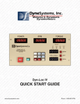
Flow Chart
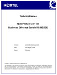
The flow chart below describes the BCM200/400 4.0 to Rls 6.0 upgrade
process.
Check the upgrade kit contents: refer to the Upgrade Kits section of this guide.
Will the BCM200/400 be at 4.0 software version, even if upgrading to 4.0 from a previous version?
No
Yes
Will you be using Data Migration Manager during the upgrade procedure?
No
Yes
Obtain & apply (for the source system) a BCM Rls 4.0 keycode
file containing Unified Messaging: refer to the Pre-Upgrade
Activities and DMM Pre-Requisites sections of this guide.
Ensure that configuration data has been
collected (for pre-4.0 systems this will require
manual replication of the config.) and that you
have obtained a BCM Rls 6.0 keycode for the
target BCM: refer to the Pre-Upgrade
Activities section of this guide.
Extract & prepare the configuration data from the source BCM:
refer to the Using Data Migration Manager to Export
Programming Data section of this guide.
Ensure that you have obtained a BCM
Rls 6.0 keycode for the target system.
Are you upgrading the BCM200 or BCM400 system?
BCM200
BCM400
Refer to the Upgrading a BCM200
Chassis section of this guide.
Refer to the Upgrading a BCM400
Chassis section of this guide.
Power up the BCM and apply the BCM Rls 6.0 keycode.
Are you using Data Migration Manager?
Apply the prepared configuration: refer to the
Applying the BCM Configuration using Data
Migration Manager section of this guide.
Yes
No
Initialise and configure the BCM: refer to
the Post-Upgrade Activities section of
this guide.
Check if any manual configuration is required:
refer to the Post Data Migration Manager
Manual Configuration section of this guide.
Perform any final actions: refer to the
Post-Upgrade Activities section of this
guide.
NN40011-049 Issue 1.3 BCM Rls 6.0
9
Upgrading a BCM 200/400
Pre-Upgrade Activities
Before proceeding with the upgrade of the BCM200 or 400 systems, it is
recommended that you perform the following actions:
Backup the configuration on the existing system in case of upgrade
failure. The original hard drive can be returned to the system, but
performing a backup is highly recommended.
Generate a new keycode file in KRS (or ask your keycode supplier to
do this) for the BCM Rls 4.0 BCM containing the supplied Unified
Messaging Authorisation Code. Applying this keycode to the Rls 4.0
BCM will allow Data Migration Manager to extract the configuration
data.
Generate an additional new BCM Rls 6.0 keycode file in KRS (or ask
your keycode supplier to do this) for the upgraded system, entering the
Keycode Migration Authorisation Code. This will be required later in the
upgrade process, when the new Base Function Tray has been installed
and the upgraded system is powered up.
Collect the configuration of the existing system, in order to re-configure
the upgraded system. This can be done by using the Data Migration
Manager application (refer to the Using Data Migration Manager to
Export Programming Data section of this guide). If not using Data
Migration Manager, use the Save Programming Record feature (not
available for pre-4.0 systems) to create an xls or html version of the
configuration. To do this during an active Element Manager session,
click on the Session menu, followed by Save Programming Record,
and select the area of data you want to save. Note that Save Selected
Data only saves the area of the screen you are viewing. Note also that
Save All Data can take up to an hour to complete.
10
NN40011-049 Issue 1.3 BCM Rls 6.0
Upgrading a BCM 200/400
Note: Some client applications such as Reporting for Contact Center will have
specific upgrade requirements. Please consult the relevant client application
documentation for upgrade information.
Note: For systems running software versions earlier than BCM Rls 4.0 (e.g.
BCM Rls 3.6 or Rls 3.7), there are two options:
a. Upgrade the system to BCM 4.0 first using the appropriate upgrade
procedures. This will allow usage of the Data Migration Manager
application to extract configuration data from the source BCM Rls
4.0 system and apply that to the upgraded BCM Rls 6.0 system.
b. Upgrade the system directly from its current software version. This
will require a complete manual reconfiguration. It will still be
necessary to upgrade the keycodes in KRS to BCM Rls 4.0 first to
allow subsequent migration of the keycodes to BCM Rls 6.0.
NN40011-049 Issue 1.3 BCM Rls 6.0
11
Upgrading a BCM 200/400
Using Data Migration Manager to Export Programming
Data
The Data Migration Manager (DMM) is a desktop tool used to migrate,
configuration and user data from BCM200/400/1000 Rls 4.0 to BCM450 Rls
6.0 system for which there is no traditional upgrade path. There are three
major steps to the DMM Migration procedure. This is in addition to the
physical setup of the new BCM system with cabling, terminals, licensing and
network setup.
The Data Migration Managers purpose is to handle telephony and CallPilot
migration, therefore aiding in the elimination of repetitive and possibly error
prone as well as time consuming manual configuration of the new BCM. Due
to its limitations not all of the system data can be automatically migrated using
the DMM tool; the engineer/installer has certain manual steps they will need to
perform after using this tool.
12
NN40011-049 Issue 1.3 BCM Rls 6.0
Upgrading a BCM 200/400
Note: Data Migration Manager is an off-line maintenance activity. Whilst DMM
is collecting or applying data from the source or target BCM, that BCM will not
be available to provide its usual services and functionality.
DMM Pre-Requisites
Before commencing the Data Migration process, please note the following.
PC Requirements
Operating System
o Windows XP SP2
o Vista
o Windows 7
o 175MB hard disk space for the DMM application
o 100MB hard disk space per source BCM for the data
Source BCM Requirements
Software version: BCM 4.0
The following Smart Update patch needs to be applied:
BCM.R400.SU.System.024-200910-1.0-1.0
Ensure the keycode file containing the Unified Messaging entitlement
has been applied
Destination BCM Requirements
Software version: BCM Rls 6.0
Ensure the keycode file containing the migrated keycodes (including
the earlier applied Unified Messaging keycode) has been applied. The
keycodes will have to have been migrated from BCM Rls 4.0 to BCM
Rls 6.0 using the supplied Keycode Migration Authorisation Code, in
KRS.
Configuration not Converted by Data Migration Manager
Please note that the following is not converted via Data Migration Manager:
FEM: DMM does not support FEM migration to BCM 6.0. Using DMM
on the source system will result in the equivalent MBMs being declared
on the target system.
Co-Existing (same bus) BRI and Loop devices: Migration to BCM 6.0
will result in a requirement to split the BRI device(s) and the Loop
device(s) onto unique buses on the 6.0. MBM Hardware declaration
must declare the BRI and Loop devices to be destined for buses on the
6.0 system such that there are no BRI and Loop devices co-existing on
the same bus (regardless of slot offset).
Greater than 130 lines configured: Migration to BCM 6.0 will result in a
reduction of line count to 130 or less. DMM will reduce IP Trunk line
count first, and if necessary continue by removing DTM interfaces from
the source’s data until 130 or fewer lines exist to be applied to the
target.
NN40011-049 Issue 1.3 BCM Rls 6.0
13
Upgrading a BCM 200/400
DMM Exceptions & Limitations
BCM Rls 4.0 Data Services: The following obsolete data services
configurations are not migrated as they do not apply to a BCM Rls 6.0 system:
These functions do not exist on the BCM Rls 6.0 system, and as such the
data does not need to be reapplied after the migration.
IPSec VPN
NAT and Filters
DNS
Web Caching
RIP/OSPF
WAN Interfaces.
VM Password: During the extraction process, DMM will perform a backup of
the source system. Part of the extraction process results in the modification of
the default VM password for mailboxes. The final step of the extraction from
the source system is a restore of the backed-up data on the source system. If
the extraction process is interrupted in mid-operation, the source system’s
default VM password may remain as the modified value.
Hardware-Less DNs: Some programming migration may fail if “HardwareLess” DNs are referenced. On a BCM Rls 4.0, source DNs that reside on a
bus for which a “Stn Mod” is not the Programmed Type will not be re-created
on a target BCM Rls 6.0 system. As a result, if on the source BCM Rls 4.0
system there were such DNs referenced in programming (e.g., as prime set,
control set, direct dial set, etc.) then the attempt to migrate that programming
onto the BCM Rls 6.0 system will fail because those DNs will not exist on the
BCM Rls 6.0 system.
CAP Assignments: DMM will not migrate CAP Assignments. The CAP
Assignments must be performed manually after the DMM migration.
Line Numbering & Line Pools: It is likely that line numbers and pools will
change after the DMM has applied the configuration to the target BCM
system. These will require checking to ensure correct line and pool
assignments.
Doorphone: No doorphone programming of any type will be migrated from
the source to the target. Manual doorphone re-configuration will be required
after the migration has been performed.
Contact Center Reporting Server Password: This is not applied to the
target system, and must be applied manually in CallPilot Manager.
User Account Passwords: All User Account passwords will be reset to the
default PlsChgMe!. These will need to be changed to their required values in
Element Manager.
14
NN40011-049 Issue 1.3 BCM Rls 6.0
Upgrading a BCM 200/400
Installing the Data Migration Manager Application
The Data Migration Manager (DMM) is available via the target BCM’s
Application Launcher, which automatically checks for updated versions of the
DMM application from the hosting servers. The Data Migration Manager will
be installed on your desktop PC and can either be opened from the
Application Launcher screen or from a desktop shortcut. The DMM User
Guide will be accessible from the Help menu option.
Note: Application Launcher can also be accessed from the Web Page button
in Element Manager.
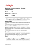
1. Open Internet Explorer.In the address field type (replacing the relevant
part with your BCM IP address): http://<bcm ip address>/
2. Click on Go, or press Return on your keyboard.
Note: You can also use the Web Page button in Element Manager to launch a
web broswer session. The BCM you wish to access must be selected in the
Element Navigation Panel to do this.
3. If you are presented with the Certificate Error window, click on
Continue to this website (not recommended).
NN40011-049 Issue 1.3 BCM Rls 6.0
15
Upgrading a BCM 200/400
4. Accept any further security messages that you may get presented with.
5. You will now see the login screen, enter your BCM User name and
Password. By default these are set to User ID: nnadmin Password:
PlsChgMe! Click on OK.
6. In the Welcome to BCM window, ensure the Main tab has been
selected, and the BCM button clicked.
16
NN40011-049 Issue 1.3 BCM Rls 6.0
Upgrading a BCM 200/400
7. The Application Launcher is displayed. Select Data Migration
Manager and click on Run.
8. The Data Migration Manager application will run.
9. Data Migration Manager can subsequently be launched from the Start
menu under Start, Programs, Avaya, Business Communication
Manager, Data Migration Manager. Alternatively, simply double-click
on the created desktop shortcut.
NN40011-049 Issue 1.3 BCM Rls 6.0
17
Upgrading a BCM 200/400
Data Collection from the Source BCM
For data collection using the Data Migration Manager (DMM), connection to
the source system can be made via either the Customer LAN or OAM LAN
interface. Prior to the extraction procedure, the DMM application ensures a
backup of the source system is performed. A restore operation will be
performed upon the completion of the extract. Because of these operations,
services to end-users of the source system will be interrupted for a period of
time since the restore process stops voicemail and will affect ICC as well.
The process of extraction can take from 20 minutes to 45 minutes. This is
dependant on the amount of data on the source system.
1. Ensure the keycode file containing the Unified Messaging Keycode has
been applied to the source BCM.
2. Start the DMM application and from the tools menu, select the
Extraction Icon
18
.
NN40011-049 Issue 1.3 BCM Rls 6.0
Upgrading a BCM 200/400
3. From the new screen, select the System Type from the dropdown list,
i.e. BCM, and click Start.
4. The DMM starts the process of collecting the data by confirming a date
and start time.
NN40011-049 Issue 1.3 BCM Rls 6.0
19
Upgrading a BCM 200/400
5. Login details for the source BCM Rls 4.0 system are required. Enter the
source BCM’s IP Address, User ID, and Password. There is also the
option to Migrate Voicemail Messages. Click OK when the details
have been entered.
6. The DMM application runs a real-time report showing the status of the
information being extracted from the 4.0 system. The process for
extraction takes between 20 – 45 minutes.
20
NN40011-049 Issue 1.3 BCM Rls 6.0
Upgrading a BCM 200/400
7. .DMM will recommend that the source system be rebooted after a
partial extraction. If this is not done, it is possible, but not probable,
that one or more MBMs may stop functioning until a BCM reboot is
done. Click OK to reboot the source BCM.
NN40011-049 Issue 1.3 BCM Rls 6.0
21
Upgrading a BCM 200/400
8. A final report displays the details of the programming extracted, with
details of warnings and errors created during the extraction from the
target system. It is possible to save a record of the report using the,
Save Report button.
22
NN40011-049 Issue 1.3 BCM Rls 6.0
Upgrading a BCM 200/400
Saving a Copy of the Extracted Data
It is possible to save all extracted information into an Excel Spreadsheet, this
is for information only. The spreadsheet should NOT be altered in any way as
record of details extracted from the system.
Saving a copy of the data is useful if you intend to apply the data to the target
system at a later date.
1. Click on the Create Excel Report icon.
2. A screen appears that allows the user to select a location to store the
details on their PC. Click Browse to select a location to save to, then
click Start.
NN40011-049 Issue 1.3 BCM Rls 6.0
23
Upgrading a BCM 200/400
3. This process generates a report prior to creation.
4. It is then possible to open the workbook and view the details over
multiple sheets within the workbook, by use of the hyperlink for each
page.
24
NN40011-049 Issue 1.3 BCM Rls 6.0
Upgrading a BCM 200/400
5. The information contained within the spreadsheet is read-only
information. Any additions or subtractions prior to application to the
new BCM system could cause the DMM apply process to fail; it is not
designed as an off-line editing program.
Reloading a Saved File
A saved DMM data file can be loaded for application to the target system. If
you do not have a saved file and are continuing from the extraction process,
please skip this section.
1. Open the File menu and select Open. Alternatively, click on the Open
icon.
NN40011-049 Issue 1.3 BCM Rls 6.0
25
Upgrading a BCM 200/400
2. Select Replace Current Data. Click Next.
3. Browse to the location of the saved file and select to upload by clicking
Next.
26
NN40011-049 Issue 1.3 BCM Rls 6.0
Upgrading a BCM 200/400
4. To load the file in to the Data Migration Manager application, select the
option to either Yes, save the workspace or No, proceed without
saving. Both options are displayed even if there is no workspace data
to save. If there is data to save a browser window opens, select the
required location and use a suitable file name. After selecting the
required option, click on Start to load the required file.
5. The DMM application reads the file and loads it to the workspace. If
required it is possible to save a report (copy of the screen detail). Click
Close to continue.
NN40011-049 Issue 1.3 BCM Rls 6.0
27
Upgrading a BCM 200/400
6. The saved file is now available to the DMM application for use by the
Preparation Wizard.
Preparing the Data for the Target System
It is possible to apply data to a target system immediately after an extract has
been performed, or after a saved data set has been loaded into Data
Migration Manager (DMM). However, first the extracted data must be
“prepared” with additional information regarding the source and target system
configuration. Data Migration Manager (DMM) presents a list of the loaded
data sets as sub-nodes under the Network node on the Data Migration
Manager (DMM) home window. If a sub-node is not visible, double-click the
Network node to expand the sub-node list.
As part of the apply operation the target’s LAN IP addresses may be changed
to match that of the source system (if applicable). Because of this, it is
recommended that the source and target system not be connected
simultaneously on the same LAN during the apply process.
The connection to the target system for the purposes of DMM apply can be
made via either the Customer LAN or OAM LAN interface.
28
NN40011-049 Issue 1.3 BCM Rls 6.0
Upgrading a BCM 200/400
To prepare the data for application to the new system:
1. Select the Data Preparation Wizard link.
2. Click on the Select Target BCM link.
3. Select the Click Here to Select Target BCM Type link.
NN40011-049 Issue 1.3 BCM Rls 6.0
29
Upgrading a BCM 200/400
4. From the drop down select the target BCM type (in this case BCM450),
and click OK.
5. A report is generated on the modification.
30
NN40011-049 Issue 1.3 BCM Rls 6.0
Upgrading a BCM 200/400
6. Click on Close and the Data Preparation Wizard screen updates, if a
mistake is made it is possible edit the destination.
7. Next is the configuration of the destinations for the Media Bay Modules,
click Click Here to Configure MBM Hardware.
NN40011-049 Issue 1.3 BCM Rls 6.0
31
Upgrading a BCM 200/400
8. The MBM Hardware configuration window describes the source
system’s hardware, and where on the source system each piece of
hardware was located. DMM makes a “best–effort” attempt at
identifying all source system hardware and associated locations;
however it is possible in certain instances for DMM to misinterpret a
source system’s hardware configuration.
9. It is important for the user to check the MBM hardware configuration
presented by DMM and if necessary make adjustments (including
possible additions or deletions) to ensure the hardware declaration
matches the source system.
32
NN40011-049 Issue 1.3 BCM Rls 6.0
Upgrading a BCM 200/400
10. This window also defines where on the target system the hardware will
reside and what associated DIP settings (if any) must be set on the
hardware for proper operation in the target system. Select the new
location for the current MBM by clicking on the drop down list and
select the required media bay module that will be located here.
NN40011-049 Issue 1.3 BCM Rls 6.0
33
Upgrading a BCM 200/400
11. Once the media bay module has been moved, ensure the details of the
module are configured correctly, either the Old Station Bus Number,
or Old Trunk Bus Number.
12. This will require to be completed for both Lines and Trunks.
34
NN40011-049 Issue 1.3 BCM Rls 6.0
Upgrading a BCM 200/400
13. Adjust the remaining MBM’s until all settings have been changed. All
old or existing modules that have been moved will need to be set to
empty.
Note: Make a note of the New DIP Settings as you will need to apply these to
the Media Bay Modules before applying the configuration to the target BCM.
14. After all required changes have been made; click on OK and Data
Migration Manager will proceed to prepare the data set based on the
declared hardware.
NN40011-049 Issue 1.3 BCM Rls 6.0
35
Upgrading a BCM 200/400
15. A summary of this preparation and its impacts will be presented in the
form of a summary report. Click on Save report to keep a record of the
changes made.
16. Click on Close and the Data Preparation Wizard screen updates. If a
mistake is made it is possible to access this screen again and re-edit
the MBM details via Click Here to Configure MBM Hardware.
36
NN40011-049 Issue 1.3 BCM Rls 6.0
Upgrading a BCM 200/400
17. The line numbers on CTM8/GATM8/8x16 MBMs will change. On the
target BCM Rls 6.0 system there will not be a 4 line gap in the line
numbering between the first set of 4 lines and the second set of 4 lines
on an 8 line MBM. The second set of 4 lines on the MBM will be
numbered continuously from the first set of 4 lines. This means that the
second set of 4 lines on every 8 line MBM will have different line
numbers on the target as compared to the original source system.
NN40011-049 Issue 1.3 BCM Rls 6.0
37
Upgrading a BCM 200/400
18. The final step is the default Mailbox password, on extraction the DMM
defaults all mailboxes to 3819. Open the screen by using the link Click
Here to input Default Mailbox Password
19. Once opened it is possible to change this prior to applying the
configuration to the new system. Note this number as all mailboxes will
have this as their password. Click OK when ready.
38
NN40011-049 Issue 1.3 BCM Rls 6.0
Upgrading a BCM 200/400
20. DMM runs the operation to confirm the settings. It is again possible to
Save report to your PC.
21. Once all the necessary steps of the Data Preparation Wizard are
successfully completed, click Close to return to the Data Migration
Manager home window where all the sub-nodes should now be green.
NN40011-049 Issue 1.3 BCM Rls 6.0
39
Upgrading a BCM 200/400
22. The data extracted or downloaded from the previous system is now
ready to be applied to the new system.
Note: Although sub section headings are visible on DMM window No
information is displayed on the right-hand side if the node is selected.
40
NN40011-049 Issue 1.3 BCM Rls 6.0
Upgrading a BCM 200/400
Upgrading a BCM400 Chassis
Use the following procedure to upgrade a BCM400 chassis to BCM400 Rls
6.0.
Note: BCM Power supply cable management is critical. Loose or incorrectly
positioned cables can result in cable damage
1. Ensure that you have made a copy of the existing configuration, have a
new keycode file containing the migrated keycodes and the Unified
Messaging keycode, and backed up the existing configuration, as
outlined in the Pre-Upgrade Actions section of this guide. If using
Data Migration Manager, ensure you have followed all the actions to
obtain and prepare the source system’s configuration ready for
application to the upgrade target system.
2. Power down the system and disconnect the power cable. Also
disconnect all other cabling from the BCM. It is advisable to place the
BCM on a flat work surface, away from the exhaust of other equipment,
allowing unhindered access to the chassis.
3. Remove the two screws securing the unit top cover to the chassis, and
remove the top cover.
NN40011-049 Issue 1.3 BCM Rls 6.0
41
Upgrading a BCM 200/400
4. With the top cover removed, disconnect the power connectors from the
IO (Input/Output) card.
42
NN40011-049 Issue 1.3 BCM Rls 6.0
Upgrading a BCM 200/400
5. Disconnect the two DS256 cables from the Media Bay Module
backplane.
NN40011-049 Issue 1.3 BCM Rls 6.0
43
Upgrading a BCM 200/400
Note: If you choose to remove the power supply, you must follow the
instructions detailed in the BCM200/400 Installation and Maintenance
Guide for replacing it and ensure cable management is followed.
6. Disconnect the hard drive power cable and IDE cable.
7. Remove the screws securing the ejection arms of the Base Function
Tray. Pull down the arms, and slide the Base Function Tray out of the
chassis.
44
NN40011-049 Issue 1.3 BCM Rls 6.0
Upgrading a BCM 200/400
8. Perform the same action on the upper Advanced Function Tray (AFT).
Remove the screws securing the ejection arms of the AFT. Pull down
the arms, and slide the AFT out of the chassis. The hard drive can be
removed.
9. Now unplug the fan power cable from the IO card.
NN40011-049 Issue 1.3 BCM Rls 6.0
45
Upgrading a BCM 200/400
10. The IDE cable from the IO card can be removed.
11. The new Chassis Interface Card uses the existing screw holes for
mounting. Remove the 2 left IO card screws.
46
NN40011-049 Issue 1.3 BCM Rls 6.0
Upgrading a BCM 200/400
12. Now place the Chassis Interface Card on top of the existing IO card
(this now performs no function other than to support the Chassis
Interface Card), align the screw holes, and screw in the 2 left hand
screws.
13. If the power supply has been removed, this can now be reinstalled.
Note: You must follow the instructions detailed in the BCM200/400
Installation and Maintenance Guide when installing the power supply
and ensure cable management is followed.
NN40011-049 Issue 1.3 BCM Rls 6.0
47
Upgrading a BCM 200/400
14. Reconnect all power cables to the CIC card. Ensure the DS256 cable is
connected to the CIC. Detach the Hard Disk Drive cables from the top
of the chassis and cable tie them to the power cables going to the
backplane.
15. Connect the DS256 cables and power cables to the to the MBM
backplane.
48
NN40011-049 Issue 1.3 BCM Rls 6.0
Upgrading a BCM 200/400
Note: Ensure that any unused, loose or unsecured cables are tied and
out of the way, to prevent any snagging, crimping or cutting of cables
when reassembling the BCM.
16. It is highly recommended that the BCM400 fan is replaced. Refer to the
Replacing the BCM400 Fan section of this guide for further details.
17. Slide in the new BCM450 BFT and replace the screws securing the
ejection arms to the BFT. The upper AFT can also be returned to its
original location.
18. From the internal viewpoint, you will see the Chassis Interface Card
align with the BCM450 BFT. Be careful not to trap any cables between
the BFT and its connector.
NN40011-049 Issue 1.3 BCM Rls 6.0
49
Upgrading a BCM 200/400
19. Check that the BFT has the Multi-Image hard drive installed by
removing the hard drive cover plate thumb screw, and removing the
plate.
20. If the hard drive is not already installed, slide it into the left hand bay (it
will come already housed in its cage) until you hear it click into place.
21. If you are installing the optional RAID hard drive, insert that in the same
manner into the right hand bay.
22. Replace the hard drive cover and thumb screw.
Note: If installing the RAID drive, please refer to the Enabling the RAID
Service after Upgrade section of the Redundancy Guide.
50
NN40011-049 Issue 1.3 BCM Rls 6.0
Upgrading a BCM 200/400
23. Replace the top cover and two securing screws.
24. The BCM400 Rls 6.0 is now ready to be returned to its original location.
Reconnect the power and any other telephony or data cabling.
Note: For information on preparing the Multi-Image hard drive for use, please
refer to the Preparing the Multi-Image Hard Drive section of the BCM450
Hardware and Installation Guide.
25. Power up the BCM and perform the post-upgrade activities (refer to the
Post Upgrade Activities section of this guide for further details). If
using Data Migration Manager as part of the upgrade process, first
refer to the Applying the BCM Configuration using Data Migration
Manager section of this guide.
Replacing the BCM400 Fan
BCM200 & 400 upgrade kits all include a replacement cooling fan. As a “good
practice” maintenance procedure it is highly recommended to replace the
existing fan with the new fan supplied. This will reduce the risk of fan failure
and the internal components overheating.
The following procedure can be applied either during the upgrade procedure
(this is advisable), or at a later date.
1. Ensure the BCM is powered down, with all cables disconnected. It is
advisable to place the BCM on a flat work surface, away from the
exhaust of other equipment, allowing unhindered access to the chassis.
NN40011-049 Issue 1.3 BCM Rls 6.0
51
Upgrading a BCM 200/400
2. Remove the two screws securing the top unit cover to the chassis, and
remove the top cover.
3. Ensure the fan power cable is disconnected.
4. From the rear of the unit, remove the four plastic pins holding the fan
onto the unit.
5. Remove the fan. Position the new fan in place with the label facing
towards the back of the chassis, and the power cable at the bottom of
the fan.
52
NN40011-049 Issue 1.3 BCM Rls 6.0
Upgrading a BCM 200/400
6. Replace the plastic pins. You may find it easier to extend the outer
sheath before locating through the pin holes in the chassis and into the
fan pin holes. Then press in the pins.
7. Connect the fan power cable to the Fan1 connector on the Chassis
Interface Card.
NN40011-049 Issue 1.3 BCM Rls 6.0
53
Upgrading a BCM 200/400
8. Replace the chassis cover and return the BCM to its original location,
or carry on with the rest of the upgrade procedure as required.
Upgrading a BCM200 Chassis
Use the following procedure to upgrade a BCM200 chassis to BCM200 Rls
6.0.
1. Ensure that you have made a copy of the existing configuration, have a
new keycode file containing the migrated keycodes and the Unified
Messaging keycode, and backed up the existing configuration, as
outlined in the Pre-Upgrade Actions section of this guide. If using
Data Migration Manager, ensure you have followed all the actions to
obtain and prepare the source system’s configuration ready for
application to the upgrade target system.
2. Power down the system and disconnect the power cable. Also
disconnect all other cabling from the BCM. It is advisable to place the
BCM on a flat work surface, away from the exhaust of other equipment,
allowing unhindered access to the chassis.
3. Remove the two screws securing the unit top cover to the chassis, and
remove the top cover.
54
NN40011-049 Issue 1.3 BCM Rls 6.0
Upgrading a BCM 200/400
4. With the top cover removed, disconnect the power connectors from the
IO (Input/Output) card.
5. Remove the two left hand screws from the I/O card. You will need
these to secure the Chassis Interface Card.
NN40011-049 Issue 1.3 BCM Rls 6.0
55
Upgrading a BCM 200/400
6. Remove the IDE cable from the I/O card.
56
NN40011-049 Issue 1.3 BCM Rls 6.0
Upgrading a BCM 200/400
7. Remove the power cable from the back of the hard drive.
8. Remove the rear hard drive access plate, and slide out the hard drive.
This will not be required in the upgraded unit.
NN40011-049 Issue 1.3 BCM Rls 6.0
57
Upgrading a BCM 200/400
9. Replace the rear plate using the four screws.
10. Unplug the DS256 and power cable (unplugged for ease of access)
from the Media Bay Module backplane.
11. It is highly recommended that the BCM200 fan is replaced. Refer to the
Replacing the BCM200 Fan section of this guide for further details.
58
NN40011-049 Issue 1.3 BCM Rls 6.0
Upgrading a BCM 200/400
12. Remove the screws securing the ejection arms of the Base Function
Tray. Pull down the arms, and slide the Base Function Tray out of the
chassis.
13. Now secure the Chassis Interface Card to the existing I/O card using
the two screws that were removed earlier. The opposite side of the
bracket should be held down by the MSC guide bracket.
NN40011-049 Issue 1.3 BCM Rls 6.0
59
Upgrading a BCM 200/400
14. Reconnect all the power cables and make sure that no cables are
loose to avoid the cables becoming trapped.
60
NN40011-049 Issue 1.3 BCM Rls 6.0
Upgrading a BCM 200/400
15. Reconnect the MBM backplane power cable, if previously unplugged.
Plug in the new DS256 connector to the backplane.
Note: Ensure that any unused, loose or unsecured cables are tied and
out of the way, to prevent any snagging, crimping or cutting of cables
when reassembling the BCM.
16. Now slide in the new BCM450 Base Function Tray (BFT). Push up the
ejection lever arms and screw in.
NN40011-049 Issue 1.3 BCM Rls 6.0
61
Upgrading a BCM 200/400
17. From the inside view you will see the BFT connector couple with the
Chassis Interface connector. Be careful not to trap any cables between
the BFT and its connector.
18. Check that the BFT has the 6.0 software-loaded hard drive installed by
removing the hard drive cover plate thumb screw, and removing the
plate.
19. If the hard drive is not already installed, slide it into the left hand bay (it
will come already housed in its cage) until you hear it click into place.
62
NN40011-049 Issue 1.3 BCM Rls 6.0
Upgrading a BCM 200/400
20. If you are installing the optional RAID hard drive, insert that in the same
manner into the right hand bay.
Note: If installing the RAID drive, please refer to the Enabling the RAID
Service after Upgrade section of the Redundancy Guide.
21. Replace the hard drive cover plate and secure with the thumb screw.
NN40011-049 Issue 1.3 BCM Rls 6.0
63
Upgrading a BCM 200/400
22. Now replace the top cover and screws.
23. The BCM200 Rls 6.0 is now ready to be returned to its original location.
Reconnect the power and any other telephony or data cabling.
Note: For information on preparing the Multi-Image hard drive for use, please
refer to the Preparing the Multi-Image Hard Drive section of the BCM450
Hardware and Installation Guide.
24. Power up the BCM and perform the post-upgrade activities (refer to the
Post Upgrade Activities section of this guide for further details). If
using Data Migration Manager as part of the upgrade process, first
refer to the Applying the BCM Configuration using Data Migration
Manager section of this guide.
64
NN40011-049 Issue 1.3 BCM Rls 6.0
Upgrading a BCM 200/400
Replacing the BCM200 Fan
BCM200 & 400 upgrade kits all include a replacement cooling fan. As a “good
practice” maintenance procedure it is highly recommended to replace the
existing fan with the new fan supplied. This will reduce the risk of fan failure
and the internal components overheating.
The following procedure can be applied either during the upgrade procedure
(this is advisable), or at a later date.
1. Ensure the BCM is powered down, with all cables disconnected. It is
advisable to place the BCM on a flat work surface, away from the
exhaust of other equipment, allowing unhindered access to the chassis.
2. Remove the two screws securing the top unit cover to the chassis, and
remove the top cover.
3. Ensure the fan power cable is disconnected.
NN40011-049 Issue 1.3 BCM Rls 6.0
65
Upgrading a BCM 200/400
4. From the rear of the unit, remove the four plastic pins holding the fan
onto the unit.
5. Remove the fan. Position the new fan in place with the label facing
towards the back of the chassis, and the power cable at the bottom of
the fan.
66
NN40011-049 Issue 1.3 BCM Rls 6.0
Upgrading a BCM 200/400
6. Replace the plastic pins. You may find it easier to extend the outer
sheath before locating through the pin holes in the chassis and into the
fan pin holes. Then press in the pins.
7. Connect the fan power cable to the Fan1 connector on the Chassis
Interface Card.
NN40011-049 Issue 1.3 BCM Rls 6.0
67
Upgrading a BCM 200/400
8. Replace the chassis cover and return the BCM to its original location,
or carry on with the rest of the upgrade procedure as required.
68
NN40011-049 Issue 1.3 BCM Rls 6.0
Upgrading a BCM 200/400
Applying the BCM Configuration using Data Migration
Manager
Once the extracted data has been through the Preparation Wizard, and all the
nodes are green. Then the data is ready to be applied to the target system.
Connection to the target system for the purposes of Data Migration Manager
can be via either the Customer’s LAN interface or OAM Port.
The process can take anywhere between 45-90 minutes depending on the
size of the data set to be migrated from the source to the target.
Note: In rare extreme cases (e.g., a large volume of voice-mail messages) the
Apply operation could take several hours.
Caution needs to be observed as part of the apply operation the target’s LAN
IP addresses may be changed to match that of the source system (if
applicable). Because of this, it is recommended that the source and target
system not be connected simultaneously on the same LAN during the apply
process.
Note: Applying data to the target system is a destructive operation, thus the
target system cannot be a live, in-use system during the apply process.
1. Set the Media Bay Module dip switch settings as per the settings noted
in the Preparing the Data for the Target System section of this guide.
2. Ensure that any other patches supplied with the upgrade kits have
been applied.
3. Ensure the migrated keycode file has been applied to the target system
before continuing with this process.
NN40011-049 Issue 1.3 BCM Rls 6.0
69
Upgrading a BCM 200/400
4. To begin applying the data to the new system, select the Apply icon
.
5. The Data Migration Manager will prompt the user to select the data
source to be used. Click Start to begin.
70
NN40011-049 Issue 1.3 BCM Rls 6.0
Upgrading a BCM 200/400
6. DMM will run a report to check the data and present a destination
screen.
7. Next, enter the IP address of the target BCM, as well as the User ID
and Password. You can also select to Migrate Voicemail Messages.
Click OK.
`
NN40011-049 Issue 1.3 BCM Rls 6.0
71
Upgrading a BCM 200/400
8. Data Migration Manager (DMM) issues a warning if using a destination
address that is different from the extraction IP address. Select Yes to
continue.
9. Once the data starts to be applied to the target, then the Keycode
warning screen appears with a table comparing like for like keycodes
that are in a greater quantity on the original system than are on the new
system.
Note: If the keycodes have been migrated from the source system to the
target system, the keycode values (count) should be the same.
10. Click Continue with Apply to continue the process.
72
NN40011-049 Issue 1.3 BCM Rls 6.0
Upgrading a BCM 200/400
11. After applying the keycodes the system then generates a report with all
the issues, warnings and errors when migrating to the new system.
12. Part the way through the migration the target system will require to be
powered down and back up again. There will be no connection to
Element Manager, so disconnect and re-connect the power supply to
do this. Click OK.
NN40011-049 Issue 1.3 BCM Rls 6.0
73
Upgrading a BCM 200/400
13. On completion a full report of all actions carried out on the migration of
data to the new system. This report can be saved if required for
reference at a later date.
14. It is recommended that you examine the results to determine what, if
any, data elements were altered or not-transferred to the target. Some
amount of manual post-DMM adjustments to the target system may be
necessary.
74
NN40011-049 Issue 1.3 BCM Rls 6.0
Upgrading a BCM 200/400
Post Data Migration Manager Manual Configuration
This following is a list of configuration may need to be configured manually
post-DMM migration, if the feature existed on the previous system.
Check that the S1/S2 addresses are set as required in DHCP Server
configuration, considering the Customer LAN or VLAN addressing
scheme.
View the Logging and Backup Schedules and check that they are set
as required.
If there are any CAP/EKEM/EKIM modules, enter them under CAP
Assignment.
IP Sets will require registration.
Sets that previously had Call Forward All Calls configured will need this
setting re-configuring.
Configure any Doorphones on the system.
All mailbox passwords will require changing from the default password
during the extract process (Default 3819).
The Starting CCR tree feature code value will need to be set as 900 is
not a valid value for BCM Rls 6.0. After DMM application, a blank value
has been entered in this field.
All user account passwords have been reset to system default
(PlsChgMe!). When accounts are migrated to the new device, the
“Change Password On Login” flag will be set. When users login (e.g. to
Element Manager), the system will automatically prompt them for a
new password. Alternatively, change the passwords in Accounts and
Privileges.
Any IVR data from the previous system will have to be entered.
All call centre agent passwords have been reset to the default value
0000 (4 zeros). These can be changed by agent first logon.
The CC Reporting Server Password will need to be reapplied, as it will
be defaulted to CCRS. Change this in CallPilot Manager.
If used then the Fax Settings->Custom Cover Page will need to be
reapplied.
Check mailbox configuration.
Check CCR Tree configuration.
NN40011-049 Issue 1.3 BCM Rls 6.0
75
Upgrading a BCM 200/400
Post-Upgrade Activities
Below is an overview of activities once the BCM 200 or 400 units have been
upgraded to BCM200/400 Rls 6.0:
76
Whilst the BCM is powered down, remove any Media Bay modules
from the main unit, set the left hand dipswitches to off, and replace in
the main unit, if not already done.
Apply the new keycode file, if not already done as part of the DMM
process.
Apply any new patches, e.g. from the Smart Update DVD, if not already
done as part of the DMM process.
If the DMM process has not been followed, initialise and re-configure
the BCM (refer to the BCM450 System Start Up Guide for the
initialisation procedure). You should refer to the .xls or html
configuration collected with the Save Programming Record feature
earlier.
Re-install client applications, including Element Manager. Refer to the
relevant client documentation for further information.
Configure any new BCM Rls 6.0 features that you require (keycodes
may be necessary to unlock some features).
NN40011-049 Issue 1.3 BCM Rls 6.0
Upgrading a BCM 200/400
Avaya Documentation Links
Upgrade Guide
NN40011-049 Issue 1.3 BCM Rls 6.0
77