1
BCM Rls 6.0
Redundancy
Task Based Guide
Redundancy
Copyright © 2010 Avaya Inc.
All Rights Reserved.
Notices
While reasonable efforts have been made to ensure that the information in this document is complete and accurate
at the time of printing, Avaya assumes no liability for any errors. Avaya reserves the right to make changes and
corrections to the information in this document without the obligation to notify any person or organization of such
changes.
Documentation disclaimer
Avaya shall not be responsible for any modifications, additions, or deletions to the original published version of
this documentation unless such modifications, additions, or deletions were performed by Avaya. End User agree to
indemnify and hold harmless Avaya, Avaya’s agents, servants and employees against all claims, lawsuits, demands
and judgments arising out of, or in connection with, subsequent modifications, additions or deletions to this
documentation, to the extent made by End User.
Link disclaimer
Avaya is not responsible for the contents or reliability of any linked Web sites referenced within this site or
documentation(s) provided by Avaya. Avaya is not responsible for the accuracy of any information, statement or
content provided on these sites and does not necessarily endorse the products, services, or information described or
offered within them. Avaya does not guarantee that these links will work all the time and has no control over the
availability of the linked pages.
Warranty
Avaya provides a limited warranty on this product. Refer to your sales agreement to establish the terms of the
limited warranty. In addition, Avaya’s standard warranty language, as well as information regarding support for
this product, while under warranty, is available to Avaya customers and other parties through the Avaya Support
Web site: http://www.avaya.com/support
Please note that if you acquired the product from an authorized reseller, the warranty is provided to you by said
reseller and not by Avaya.
Licenses
THE SOFTWARE LICENSE TERMS AVAILABLE ON THE AVAYA WEBSITE,
HTTP://SUPPORT.AVAYA.COM/LICENSEINFO/ ARE APPLICABLE TO ANYONE WHO DOWNLOADS,
USES AND/OR INSTALLS AVAYA SOFTWARE, PURCHASED FROM AVAYA INC., ANY AVAYA
AFFILIATE, OR AN AUTHORIZED AVAYA RESELLER (AS APPLICABLE) UNDER A COMMERCIAL
AGREEMENT WITH AVAYA OR AN AUTHORIZED AVAYA RESELLER. UNLESS OTHERWISE
AGREED TO BY AVAYA IN WRITING, AVAYA DOES NOT EXTEND THIS LICENSE IF THE
SOFTWARE WAS OBTAINED FROM ANYONE OTHER THAN AVAYA, AN AVAYA AFFILIATE OR AN
AVAYA AUTHORIZED RESELLER, AND AVAYA RESERVES THE RIGHT TO TAKE LEGAL ACTION
AGAINST YOU AND ANYONE ELSE USING OR SELLING THE SOFTWARE WITHOUT A LICENSE. BY
INSTALLING, DOWNLOADING OR USING THE SOFTWARE, OR AUTHORIZING OTHERS TO DO SO,
YOU, ON BEHALF OF YOURSELF AND THE ENTITY FOR WHOM YOU ARE INSTALLING,
DOWNLOADING OR USING THE SOFTWARE (HEREINAFTER REFERRED TO INTERCHANGEABLY
AS "YOU" AND "END USER"), AGREE TO THESE TERMS AND CONDITIONS AND CREATE A
BINDING CONTRACT BETWEEN YOU AND AVAYA INC. OR THE APPLICABLE AVAYA AFFILIATE
("AVAYA").
Copyright
Except where expressly stated otherwise, no use should be made of the Documentation(s) and Product(s) provided
by Avaya. All content in this documentation(s) and the product(s) provided by Avaya including the selection,
arrangement and design of the content is owned either by Avaya or its licensors and is protected by copyright and
other intellectual property laws including the sui generis rights relating to the protection of databases. You may not
modify, copy, reproduce, republish, upload, post, transmit or distribute in any way any content, in whole or in part,
including any code and software. Unauthorized reproduction, transmission, dissemination, storage, and or use
without the express written consent of Avaya can be a criminal, as well as a civil offense under the applicable law.
Third Party Components
Certain software programs or portions thereof included in the Product may contain software distributed under third
party agreements ("Third Party Components"), which may contain terms that expand or limit rights to use certain
portions of the Product ("Third Party Terms"). Information regarding distributed Linux OS source code (for those
Products that have distributed the Linux OS source code), and identifying the copyright holders of the Third Party
Components and the Third Party Terms that apply to them is available on the Avaya Support Web site:
http://support.avaya.com/Copyright.
Trademarks
The trademarks, logos and service marks ("Marks") displayed in this site, the documentation(s) and product(s)
provided by Avaya are the registered or unregistered Marks of Avaya, its affiliates, or other third parties. Users
are not permitted to use such Marks without prior written consent from Avaya or such third party which may own
the Mark. Nothing contained in this site, the documentation(s) and product(s) should be construed as granting, by
implication, estoppel, or otherwise, any license or right in and to the Marks without the express written permission
of Avaya or the applicable third party. Avaya is a registered trademark of Avaya Inc. All non-Avaya trademarks
are the property of their respective owners.
2
NN40011-048 Issue 1.2 BCM450 Rls 6.0
Redundancy
Downloading documents
For the most current versions of documentation, see the Avaya Support. Web site: http://www.avaya.com/support
Contact Avaya Support
Avaya provides a telephone number for you to use to report problems or to ask questions about your product. The
support telephone number is 1-800-242-2121 in the United States. For additional support telephone numbers, see
the Avaya Web site: http://www.avaya.com/support
Copyright © 2010 ITEL, All Rights Reserved
The copyright in the material belongs to ITEL and no part of the material may
be reproduced in any form without the prior written permission of a duly
authorised representative of ITEL.
NN40011-048 Issue 1.2 BCM450 Rls 6.0
3
Redundancy
Table of Contents
Redundancy ...................................................................... 5
Overview .......................................................................................... 5
RAID Keycode ...................................................................................................6
Flowchart ......................................................................................... 7
Preparing the BCM 450 for Redundancy Kit Installation .................. 8
Removing the Fan..............................................................................................9
Removing the Power Supply ...........................................................................11
Removing the Front Hard Drive Cover ............................................................15
Completed Pre-Preparation Check List ......................................... 16
Installing the Redundancy & RAID Kit............................................ 17
Installing the Secondary Fan and Faceplate ...................................................17
Installing the Redundant Power Supply ...........................................................22
Installing the Secondary Hard Disk Drive ........................................................28
Enabling the RAID Service after Upgrade...................................... 29
Hard Disk Drive/ RAID LED States ..................................................................31
Avaya Documentation Links .......................................... 33
4
NN40011-048 Issue 1.2 BCM450 Rls 6.0
Redundancy
Redundancy
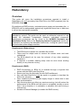
Overview
This guide will cover the installation procedures required to install a
Redundancy kit and secondary Hard Disk Drive (for RAID purposes) into the
BCM 450 chassis.
By combining a RAID solution, redundant power supply and secondary fan - a
BCM 450 can be safeguarded against any significant down time or data loss
in all but the most severe scenarios.
Note: BCM450 systems can also be ordered pre-installed with the
redundancy options. This guide can be used as referential material to help
identify the redundant components. However, redundant component
replacement procedures can be found in the BCM450 Hardware and
Installation Guide. Refer to the Replacing Internal Components section for
information on replacing the redundant hard drives, cooling fan, power supply,
and redundant power supply modules.
Requirements (Redundancy):
The BCM must be placed on a suitable flat surface.
There must be ample room to remove the access cover and work
unhindered.
The BCM should not be near the exhaust of any other operating
equipment.
If required, a suitable earthing strap must be worn when working
directly on any internal circuitry.
Requirements (RAID):
RAID functionality on BCM 6.0 is enabled through a keycode that
comes with the RAID Hard Disk Drive.
Ensure you have the Keycode file with RAID entitlement.
Any new Hard Disk Drive must be equal to or greater in size than the
drive to be mirrored.
Once installed the BCM will take slightly longer to reboot due to new
disk synchronisation.
Disk mirroring does not effect any services running, but will reduce the
performance of the BCM until the mirror is completed (usually no more
than 1 hour) therefore it is advisable to schedule this work during a
quiet period.
Access to Element Manager (to enable the RAID service).
NN40011-048 Issue 1.2 BCM450 Rls 6.0
5
Redundancy
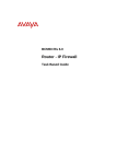
RAID Keycode
Note: If installing the RAID kit, ensure that the RAID Keycode is showing as
active – otherwise the RAID service will not be enabled.
6
NN40011-048 Issue 1.2 BCM450 Rls 6.0
Redundancy
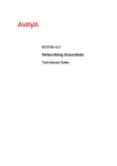
Flowchart
This flowchart depicts the steps necessary to upgrade a BCM 450 with a
redundancy kit and RAID kit.
Check that you meet the Requirements for upgrading the BCM with a
Redundancy or RAID Kit: Refer to the Overview section of this guide
Prepare the BCM 450 for upgrade: Refer to the Preparing the BCM
450 for Redundancy Kit Installation section of this guide
Check that you have the required components to install: Refer to the
Installing the Redundancy & RAID Kit section of this guide
Install a Secondary Fan and Faceplate: Refer to the Installing the
Secondary Fan and Faceplate section of this guide
Install a Redundant Power Supply: Refer to the Installing the
Redundant Power Supply section of this guide
Install a Secondary Hard Disk Drive: Refer to the Installing the
Secondary Hard Disk Drive section of this guide
Check that the RAID service is enabled: Refer to the Enabling the
RAID Service after Upgrade section of this guide
NN40011-048 Issue 1.2 BCM450 Rls 6.0
7
Redundancy
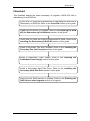
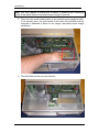
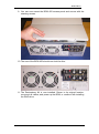
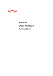
Preparing the BCM 450 for Redundancy Kit
Installation
Before installing a Redundancy kit, the BCM 450 must have the relevant
components removed, whilst preparing the chassis to accommodate the new
hardware. Components affected by the installation are shown in the
photographs below:
Rear of the BCM 450
Front of the BCM 450
8
NN40011-048 Issue 1.2 BCM450 Rls 6.0
Redundancy
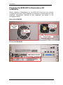
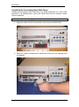
Removing the Fan
To install the secondary fan and cover plate, the existing components need to
be removed.
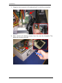
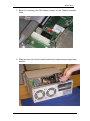
1. First, remove the retaining screws and access panel of the BCM 450.
2. You can clearly see the fan, power cable and connection point to the
main circuit board.
NN40011-048 Issue 1.2 BCM450 Rls 6.0
9
Redundancy
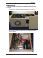
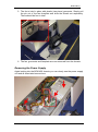
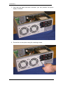
3. Grasp the fan connector at the plug and pull to undo the connection.
4. Next, remove all retaining screws from the rear fan faceplate. The
panel can now be removed.
10
NN40011-048 Issue 1.2 BCM450 Rls 6.0
Redundancy
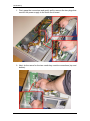
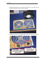
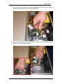
5. The fan is held in place with plastic (two piece) grommets. Simply pull
the pin out of the fan faceplate and slide the sheath out separately.
There should be four in total.
6. The fan, grommets and faceplate are now removed from the chassis.
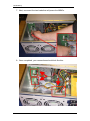
Removing the Power Supply
Again looking into the BCM 450 chassis you can clearly see the power supply
unit and all associated connections.
NN40011-048 Issue 1.2 BCM450 Rls 6.0
11
Redundancy
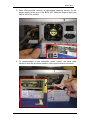
1. First, grasp the connectors and gently pull to remove the two plugs that
connect the power supply to the main circuit board.
2. Next, do the same for the two media bay module connections (top and
bottom).
12
NN40011-048 Issue 1.2 BCM450 Rls 6.0
Redundancy
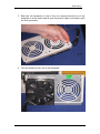
3. Once disconnected, remove all associated retaining screws for the
power supply at the rear of the BCM 450. Slide the power supply and
cables out of the chassis.
4. To accommodate a new redundant power supply, the small plate
utilised to hold the previous (smaller) unit in place must be removed.
NN40011-048 Issue 1.2 BCM450 Rls 6.0
13
Redundancy
Note: You may require a cutting tool to assist in breaking the connection
struts of this panel before it becomes loose enough to remove.
5. There are two small retaining lips on the internal power supply bracket.
If not already done, the one closest to the main circuit board must be
removed or flattened to allow for the (larger) redundant power supply
installation.
6. The BCM 450 should now look like this.
14
NN40011-048 Issue 1.2 BCM450 Rls 6.0
Redundancy
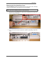
Removing the Front Hard Drive Cover
The final preparation task is to remove the Front Hard Drive cover, allowing
access to the slot where a secondary drive can be installed.
Note: If you are not installing a RAID kit, skip this section.
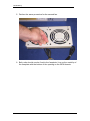
1. At the front of the BCM 450, unscrew the retaining bolt and pull the
cover to remove the panel.
2. You now have the access required to install the secondary Hard Disk
Drive.
NN40011-048 Issue 1.2 BCM450 Rls 6.0
15
Redundancy
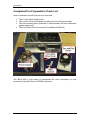
Completed Pre-Preparation Check List
Upon completion ensure that you have removed:
The current Power Supply Unit.
The current Fan and faceplate (including the four fixing grommets).
The rear bracket/ plate (removed to accommodate the new redundant
power supply unit).
The Front Hard Drive Cover plate (if installing a RAID kit).
The BCM 450 is now ready to incorporate the new redundancy kit and
secondary Hard Disk Drive (for RAID purposes).
16
NN40011-048 Issue 1.2 BCM450 Rls 6.0
Redundancy
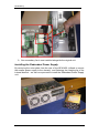
Installing the Redundancy & RAID Kit
For the purpose of this guide, we will install the following components:
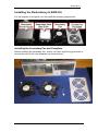
Installing the Secondary Fan and Faceplate
Before installing the secondary fan, ensure you have eight fixing grommets to
secure the units to the new faceplate (as shown below):
NN40011-048 Issue 1.2 BCM450 Rls 6.0
17
Redundancy
1. Starting with the first unit, ensure the fan label is the right way up
(power lead should rest on the work surface).
2. Separate the pins from the grommets to use in the order shown below:
18
NN40011-048 Issue 1.2 BCM450 Rls 6.0
Redundancy
3. Rest the fan faceplate on top of the unit (ensure that the lip of the
faceplate is at the same end as your fan power cable) and secure with
the four grommets.
4. This will attach the fan unit to the faceplate.
NN40011-048 Issue 1.2 BCM450 Rls 6.0
19
Redundancy
5. Perform the same procedure for the second fan.
6. Both units should now be fixed to the faceplate. Line up the metal lip of
the faceplate with the bottom of the opening on the BCM chassis.
20
NN40011-048 Issue 1.2 BCM450 Rls 6.0
Redundancy
7. Secure the faceplate to the chassis with the fixing screws.
8. Finally, clip both power connectors into the sockets located on the main
circuit board.
NN40011-048 Issue 1.2 BCM450 Rls 6.0
21
Redundancy
9. Your secondary fan is now installed alongside the original unit.
Installing the Redundant Power Supply
By removing the extra plate from the rear of the BCM 450 (utilised to secure
the smaller power supply to the chassis), and flattening the retaining lip of the
internal bracket – we can now proceed to install the Redundant Power Supply
unit.
22
NN40011-048 Issue 1.2 BCM450 Rls 6.0
Redundancy
1. Begin by removing the PSU Status jumper on the Chassis Interface
Card.
2. Slide the new unit into the chassis where the original power supply was
located.
NN40011-048 Issue 1.2 BCM450 Rls 6.0
23
Redundancy
3. Now that the plate has been removed, you can position the power
supply as shown.
4. Screw the unit into place using the retaining screws.
24
NN40011-048 Issue 1.2 BCM450 Rls 6.0
Redundancy
5. Tidy away the cables as necessary, separating the same four leads
that will connect the new unit to the BCM 450.
6. Use the largest and smallest plugs to connect the redundant power
supply to the main circuit board.
NN40011-048 Issue 1.2 BCM450 Rls 6.0
25
Redundancy
7. Next, reconnect the two leads that will power the MBM’s.
8. Once completed, your connections should look like this.
26
NN40011-048 Issue 1.2 BCM450 Rls 6.0
Redundancy
9. You can now reseat the BCM 450 access panel and secure with the
retaining screws.
10. The rear of the BCM 450 should now look like this:
11. The Redundancy Kit is now installed. Return to its original location,
reconnect all cables, and power up the BCM, or continue with installing
the RAID drive.
NN40011-048 Issue 1.2 BCM450 Rls 6.0
27
Redundancy
Installing the Secondary Hard Disk Drive
Installing a secondary Hard Disk Drive (for RAID purposes) is a very short
process. If not already done, pre fit the Hard Drive into the relevant cradle.
Once completed:
Note: If you are not installing the RAID hard drive, skip this section.
1. Align the cradle into the vacant slot on the front of the BCM 450.
2. Push the cradle (containing the Hard Disk Drive) into the opening until
it is seated.
28
NN40011-048 Issue 1.2 BCM450 Rls 6.0
Redundancy
3. The secondary Hard Disk Drive is now installed. Replace the front Hard
Drive cover and tighten the retaining screw.
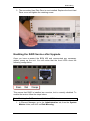
Enabling the RAID Service after Upgrade
Once you have re-seated the BCM 450 and reconnected any necessary
cables, power up the unit. You will notice that the front LED’s show the
following configuration:
This means that RAID is installed as a service, but is currently disabled. To
enable the service follow the steps below:
Note: Enabling the RAID service will initiate a BCM reboot.
1. In Element Manager, go to the Administration tab, then the System
Metrics folder, and click on Disk Mirroring.
NN40011-048 Issue 1.2 BCM450 Rls 6.0
29
Redundancy
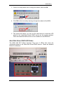
Note: The Disk Mirroring option only becomes visible after RAID keycode
entry.
2. If the Admin Status is set to Disabled, click on the Change button. If
the status is set to Enabled, you do not need to perform any further
action.
30
NN40011-048 Issue 1.2 BCM450 Rls 6.0
Redundancy
3. Click on the drop down list to change the status, and click OK.
4. Click OK to the secondary warning to begin the reboot of the BCM.
5. The system will reboot, you can use the chart below to check the LED
states of the Hard Disk Drives/ RAID service as the system restarts.
Once rebooted the RAID service is now enabled on the BCM 450.
Hard Disk Drive/ RAID LED States
The BCM 450 BFT (Base Function Tray) has 3 LED’s that show the
operational states of the Hard Disk Drives/ RAID service. These are detailed
below for reference:
NN40011-048 Issue 1.2 BCM450 Rls 6.0
31
Redundancy
LED States
HDD-1 LED
RAID LED
HDD-2 LED
Green
Green
Green
Green
Off
Off
Green
Off
Orange
Green
Red
Off
Green
Red
Orange
Green
Red
Red
Green
Green
Blink
Orange Blink
32
Description
- BCM completed booting, two hard drives
are present and synchronized, RAID is
functioning properly
- BCM is not RAID capable, one hard drive
is present
- BCM is not RAID capable, two hard drives
are present
- BCM is RAID capable, but only one hard
drive is present
- BCM is RAID capable, two hard drives are
present but RAID has been administratively
disabled by the user
- BCM is RAID capable, two hard drives are
present, RAID is enabled but one of the
hard drives has failed
- BCM is RAID capable, two hard drives are
present and are currently synchronising
NN40011-048 Issue 1.2 BCM450 Rls 6.0
Redundancy
Avaya Documentation Links
Troubleshooting Guide
Installation – System
Maintenance
NN40011-048 Issue 1.2 BCM450 Rls 6.0
33