1
BCM Rls 6.0
VLANs
Task Based Guide
VLANs
Copyright © 2010 Avaya Inc.
All Rights Reserved.
Notices
While reasonable efforts have been made to ensure that the information in this document is complete and accurate
at the time of printing, Avaya assumes no liability for any errors. Avaya reserves the right to make changes and
corrections to the information in this document without the obligation to notify any person or organization of such
changes.
Documentation disclaimer
Avaya shall not be responsible for any modifications, additions, or deletions to the original published version of
this documentation unless such modifications, additions, or deletions were performed by Avaya. End User agree to
indemnify and hold harmless Avaya, Avaya’s agents, servants and employees against all claims, lawsuits, demands
and judgments arising out of, or in connection with, subsequent modifications, additions or deletions to this
documentation, to the extent made by End User.
Link disclaimer
Avaya is not responsible for the contents or reliability of any linked Web sites referenced within this site or
documentation(s) provided by Avaya. Avaya is not responsible for the accuracy of any information, statement or
content provided on these sites and does not necessarily endorse the products, services, or information described or
offered within them. Avaya does not guarantee that these links will work all the time and has no control over the
availability of the linked pages.
Warranty
Avaya provides a limited warranty on this product. Refer to your sales agreement to establish the terms of the
limited warranty. In addition, Avaya’s standard warranty language, as well as information regarding support for
this product, while under warranty, is available to Avaya customers and other parties through the Avaya Support
Web site: http://www.avaya.com/support
Please note that if you acquired the product from an authorized reseller, the warranty is provided to you by said
reseller and not by Avaya.
Licenses
THE SOFTWARE LICENSE TERMS AVAILABLE ON THE AVAYA WEBSITE,
HTTP://SUPPORT.AVAYA.COM/LICENSEINFO/ ARE APPLICABLE TO ANYONE WHO DOWNLOADS,
USES AND/OR INSTALLS AVAYA SOFTWARE, PURCHASED FROM AVAYA INC., ANY AVAYA
AFFILIATE, OR AN AUTHORIZED AVAYA RESELLER (AS APPLICABLE) UNDER A COMMERCIAL
AGREEMENT WITH AVAYA OR AN AUTHORIZED AVAYA RESELLER. UNLESS OTHERWISE
AGREED TO BY AVAYA IN WRITING, AVAYA DOES NOT EXTEND THIS LICENSE IF THE
SOFTWARE WAS OBTAINED FROM ANYONE OTHER THAN AVAYA, AN AVAYA AFFILIATE OR AN
AVAYA AUTHORIZED RESELLER, AND AVAYA RESERVES THE RIGHT TO TAKE LEGAL ACTION
AGAINST YOU AND ANYONE ELSE USING OR SELLING THE SOFTWARE WITHOUT A LICENSE. BY
INSTALLING, DOWNLOADING OR USING THE SOFTWARE, OR AUTHORIZING OTHERS TO DO SO,
YOU, ON BEHALF OF YOURSELF AND THE ENTITY FOR WHOM YOU ARE INSTALLING,
DOWNLOADING OR USING THE SOFTWARE (HEREINAFTER REFERRED TO INTERCHANGEABLY
AS "YOU" AND "END USER"), AGREE TO THESE TERMS AND CONDITIONS AND CREATE A
BINDING CONTRACT BETWEEN YOU AND AVAYA INC. OR THE APPLICABLE AVAYA AFFILIATE
("AVAYA").
Copyright
Except where expressly stated otherwise, no use should be made of the Documentation(s) and Product(s) provided
by Avaya. All content in this documentation(s) and the product(s) provided by Avaya including the selection,
arrangement and design of the content is owned either by Avaya or its licensors and is protected by copyright and
other intellectual property laws including the sui generis rights relating to the protection of databases. You may not
modify, copy, reproduce, republish, upload, post, transmit or distribute in any way any content, in whole or in part,
including any code and software. Unauthorized reproduction, transmission, dissemination, storage, and or use
without the express written consent of Avaya can be a criminal, as well as a civil offense under the applicable law.
Third Party Components
Certain software programs or portions thereof included in the Product may contain software distributed under third
party agreements ("Third Party Components"), which may contain terms that expand or limit rights to use certain
portions of the Product ("Third Party Terms"). Information regarding distributed Linux OS source code (for those
Products that have distributed the Linux OS source code), and identifying the copyright holders of the Third Party
Components and the Third Party Terms that apply to them is available on the Avaya Support Web site:
http://support.avaya.com/Copyright.
Trademarks
The trademarks, logos and service marks ("Marks") displayed in this site, the documentation(s) and product(s)
provided by Avaya are the registered or unregistered Marks of Avaya, its affiliates, or other third parties. Users
are not permitted to use such Marks without prior written consent from Avaya or such third party which may own
the Mark. Nothing contained in this site, the documentation(s) and product(s) should be construed as granting, by
implication, estoppel, or otherwise, any license or right in and to the Marks without the express written permission
of Avaya or the applicable third party. Avaya is a registered trademark of Avaya Inc. All non-Avaya trademarks
are the property of their respective owners.
2
NN40011-050 Issue 1.2 BCM Rls 6.0
VLANs
Downloading documents
For the most current versions of documentation, see the Avaya Support. Web site: http://www.avaya.com/support
Contact Avaya Support
Avaya provides a telephone number for you to use to report problems or to ask questions about your product. The
support telephone number is 1-800-242-2121 in the United States. For additional support telephone numbers, see
the Avaya Web site: http://www.avaya.com/support
Copyright © 2010 ITEL, All Rights Reserved
The copyright in the material belongs to ITEL and no part of the material may
be reproduced in any form without the prior written permission of a duly
authorised representative of ITEL.
NN40011-050 Issue 1.2 BCM Rls 6.0
3
VLANs
Table of Contents
VLANs ................................................................................ 5
Overview .................................................................................................. 5
Benefits of VLANs ..............................................................................................6
BCM VLANs, DHCP, and the Published IP Address .........................................6
Allow Network Access .......................................................................................7
Auto-Discovery for IP Phones ............................................................................7
Supported VLANs ..............................................................................................7
BCM LAN Ports and VLANs ..............................................................................8
Example VLAN Network Scenario .....................................................................9
Required Information ................................................................................ 9
Flow Chart .............................................................................................. 10
Configuration .......................................................................................... 11
Configuring VLANs ..........................................................................................11
Setting the Published IP Address ....................................................................13
Configuring VLAN DHCP Address Ranges .....................................................16
Additional Information .................................................... 19
Configuring Static Routes ....................................................................... 19
Avaya Documentation Links .......................................... 21
4
NN40011-050 Issue 1.2 BCM Rls 6.0
VLANs
VLANs
Overview
Virtual LANs (VLANs) were designed to enable creation of multiple logical
networks using common hardware. If a network administrator wanted to
create separate logical networks but did not have a VLAN capable device,
they would have to have a separate switch (or groups of switches) for each
network they wanted to create, as below:
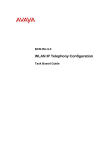
With a VLAN device such as a VLAN capable switch, separate logical
networks can be created using common hardware. A simple example is
shown below:
VLAN switch
VLAN ID: 1
HR Dept.
NN40011-050 Issue 1.2 BCM Rls 6.0
VLAN ID: 2
Support Dept.
5
VLANs
This example shows how two logical networks can be kept separate, and in
effect, cannot “see” each other.
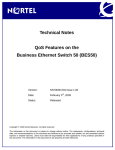
Another function of VLANs is to create logical networks across geographically
dispersed sections within a company, as illustrated below.
VLAN ID: 1
VLAN ID: 2
VLAN ID: 3
VLAN ID: 1
VLAN ID: 2 VLAN ID: 7
VLAN switch
VLAN switch
Trunk Link
The VLAN switches should be capable of VLAN tagging to be able to link
VLANs across multiple VLAN switches.
Benefits of VLANs
VLANs have a number of advantages over traditional LANs:
Increase in network Performance: In networks with a high
percentage of broadcasts and multicasts, VLAN reduces the possibility
of sending the broadcast and multicast packets to unwanted
destinations, i.e. broadcasts are kept within each VLAN.
Virtual Group Formation: Virtual workgroups in a VLAN facilitates
increased communication between the members of the workgroup and
restricts broadcasts and multicasts within a network.
Simplified Administration: VLAN simplifies the task of the addition
and modification of users in the network.
Security: Increased security due to computer’s/network devices on the
different VLAN’s not being able to “see” each other. Also, this feature
allows a separate VLAN for Management purposes.
BCM VLANs, DHCP, and the Published IP Address
On creating a VLAN on the BCM, corresponding DHCP ranges can also be
configured to serve DHCP clients residing on the VLAN. For example, you
may wish to create a VLAN specifically for IP Phones. After creating that
VLAN, the DHCP configuration area will allow a range of addresses to be
configured to issue to those IP Phones residing on that VLAN.
With the creation of VLANs, possibly for the purpose of segregating IP Phone
and other network traffic, consideration should be given to the Published IP
Address selection. The Published IP Address is the address that VoIP
applications (IP Phones, VoIP trunks etc.) and LAN CTE should register
6
NN40011-050 Issue 1.2 BCM Rls 6.0
VLANs
against (refer to the IP Telephony Guide for more information). The possible
options will be:
The Customer LAN address, or
Any of the BCM VLAN IP Addresses.
Allow Network Access
This feature allows traffic from one VLAN destined for other networks, or
VLANs, to be forwarded. For example, if there is a VLAN created for IP
Phones and those IP Phones need to communicate with IP Softphones on
PCs residing on a separate VLAN, Allow Network Access can be enabled to
facilitate this. Conversely, if the IP Softphones need to communicate with the
regular IP Phones, Allow Network Access should be enabled on the VLAN
that they reside on.
By default Allow Network Access (ANA) is disabled. This means that all traffic
on one VLAN traversing via the BCM to other networks will be discarded.
Note: Allow Network Access acts as a routing facility. Network routers can
also route traffic between the VLANs if they are accessible to the VLANs, and
are configured to do so.
Note: VLAN routed traffic is processed by the BCM CPU. Consider your
planning of VLAN routing so that VLAN routed traffic does not overload the
BCM processor, particularly in the case of the BCM50 where the processing
capability is not as great as the BCM450. You can check the processor usage
via BCM Monitor to ensure that the BCM is not overloaded.
Auto-Discovery for IP Phones
In a scenario where there are a number of VLANs configured in addition to the
Customer LAN, each with a DHCP Address Range configured, the AutoDiscovery feature can be used on IP Phones to automatically query which
VLAN it should be assigned to.
Firstly, the IP set requests an IP Address from the Customer LAN. Once
obtained, this is immediately released and queries are made for an IP
Address from each VLAN ID in turn, until an address is found on the
appropriate VLAN for IP Phones.
Note: This feature is supported on DHCP servers with the Avaya vendor
specific IP sets
.
Supported VLANs
The BCM50 supports 4 VLANs and the BCM450 supports 8 VLANs.
NN40011-050 Issue 1.2 BCM Rls 6.0
7
VLANs
BCM LAN Ports and VLANs
A VLAN can be assigned to either all network ports on the BCM, or just to a
single port. This option can be selected when creating the VLANs on the
BCM, in the IP Subsystem- VLAN Interfaces configuration area.
Note: VLANs cannot be assigned to the OAM port.
Note: The Customer LAN is unmanaged and can be accessed across all LAN
ports.
The BCM50’s ports are referenced as below in relation to VLAN assignments:
Note: VLANs cannot be assigned to the ports on the BCM50(b)e or
BCM50(b)a integrated router card.
The BCM450’s ports are referenced as below in relation to VLAN
assignments:
8
NN40011-050 Issue 1.2 BCM Rls 6.0
VLANs
Example VLAN Network Scenario
Below shows how the BCM may be configured to reside in a network
configured for VLANs. An example VLAN configuration relating to the BCM
could be:
VLAN ID:11, Subnet 192.168.11.0, used for Client Apps
VLAN ID:12, Subnet 192.168.12.0, hosting IP Phones
VLAN ID:13, Subnet 192.168.13.0, for management access
The Customer LAN is unmanaged and accessible on all LAN ports.
This diagram is a logical representation. The attached network equipment
must be configured correctly for VLAN working, e.g. LAN 2 above should be
connected to VLAN equipment supporting VLAN ID 12.
Required Information
VLAN networking requires careful planning and consideration. The BCM is
only one element of a VLAN network, and so BCM configuration should ideally
take place after a network plan has been prepared.
With this in mind, ascertain the following information before configuring the
BCM for VLAN working:
The VLAN ID’s on the network the BCM will need to reside on.
The BCM VLAN IP Addresses.
If the BCM is issuing DHCP addresses on the VLANs (e.g. for IP
Phones), you will need DHCP Address Ranges for those VLANs.
If VLANs are to be configured, which of the BCM’s IP Addresses
(Customer LAN or VLAN) should be the Published IP Address (for VoIP
services to register against etc.)?
What is the BCM system Default Gateway, and also what are the
Default Gateways for the VLAN DHCP Address Ranges (if using DHCP
on a VLAN)?
NN40011-050 Issue 1.2 BCM Rls 6.0
9
VLANs
Flow Chart
The flow chart below shows a recommended order for configuring the BCM for
VLAN working.
Ensure you have a network plan detailing VLAN ID’s and
physical connections.
Configure the BCM to reside on the required VLANs:
refer to the Configuring VLANs section of this guide.
Check that the Published IP Address is correctly
defined for VoIP services to register against: refer to
the Setting the Published IP Address section of this
guide.
If using the BCM as a DHCP server for VLAN network
subnets,
configure
DHCP
Address
Ranges
accordingly: refer to the Configuring VLAN DHCP
Address Ranges section of this guide.
10
NN40011-050 Issue 1.2 BCM Rls 6.0
VLANs
Configuration
When network requirements planning has been performed, and the Customer
LAN and VLAN addresses are known, the VLANs can then be created.
Configuring VLANs
Use the following procedure to create and enter the BCM into a VLAN.
1. In the Element Manager Configuration tab, open the System folder,
and click on the IP Subsystem link.
2. Click on the VLAN Interfaces tab.
NN40011-050 Issue 1.2 BCM Rls 6.0
11
VLANs
3. To configure the BCM to be part of a VLAN, click on the Add button.
4. In the Add a VLAN box, enter:
a. VLAN ID: The VLAN ID (range is 1 – 4094).
b. Name: An identifying name for this VLAN.
c. IP Address: The IP Address for the BCM in the VLAN subnet.
d. Subnet Mask: The VLAN subnet mask.
5. The VLAN entry will be added to the list. Repeat as required for as
many VLANs as are necessary, up to the maximum supported by the
BCM as stated earlier.
12
NN40011-050 Issue 1.2 BCM Rls 6.0
VLANs
6. When the VLAN(s) are entered in the list, you should select for each
VLAN which ports support that VLAN. The choice is to select one port
only, or all ports.
Note: If you have selected a specific port, ensure that port is physically
connected to the network that will allow access to that VLAN.
7. Select whether or not the VLAN should Allow Network Access. This
option, if enabled, allows traffic on the VLAN destined for other
networks to be forwarded from the VLAN.
Setting the Published IP Address
The Published IP Interface is the IP Address that IP Telephones need to
register against as well as the address that VoIP gateways need to be
“pointed” towards. You have the choice of selecting the Customer LAN (refer
to the Configuring the LAN IP Address section of the System Start Up
Guide) or any VLAN IP Addresses that are configured on the BCM in the IP
Subsystem section of Element Manager.
The Published IP Address must be set as the S1 IP (or S2 IP if the BCM will
be used as a “backup” registration BCM) when configuring IP phones for
registration.
Note: The Published IP Address is the address that LAN CTE should also
register against. For further information, refer to the LAN CTE Guide.
Note: For further information concerning the Published IP Address in relation
to VoIP, refer to the IP Telephony Guide.
NN40011-050 Issue 1.2 BCM Rls 6.0
13
VLANs
Use the following procedure to check or set the Published IP Address.
1. From the Configuration tab, open the System folder and select IP
Subsystem. Click on the General Settings tab.
2. If checking the existing Published IP Address, view the read-only
field.
14
NN40011-050 Issue 1.2 BCM Rls 6.0
VLANs
3. If changing the setting, from the Published IP Interface drop-down list,
select the Customer LAN or any of the VLANs configured on the BCM.
4. A warning box will appear stating that all Voice over IP applications will
be restarted. This may result in VoIP calls being dropped. Click OK to
continue.
5. If changed, the new setting will be displayed,
NN40011-050 Issue 1.2 BCM Rls 6.0
15
VLANs
6. Changing the Published IP Interface setting also has the effect of
changing the S1 Primary Terminal Proxy Server IP Addresses (S1 &
S2) in the DHCP Server IP Terminal DHCP Options screen.
Configuring VLAN DHCP Address Ranges
If VLANs have been configured on the system, it may be necessary to
configure an address range relating to that VLAN to issue IP Addresses to
DHCP clients on that VLAN. For example, if a VLAN has been created
specifically for IP Phones and the BCM is acting as a DHCP server for the IP
Phones, it will be necessary to create a range of IP Addresses on the VLAN
subnet to issue to IP Phones.
Use the following procedure to set an Address Range.
The IP Addresses to be issued to DHCP clients are entered in this section. If
the DHCP mode is set to Enabled – IP Phones Only then the Address
Range entered here will only relate to IP Phones.
16
NN40011-050 Issue 1.2 BCM Rls 6.0
VLANs
1. In Element Manager, select the Configuration tab and open the Data
Services folder and select DHCP Server.
2. Select the Address Ranges tab. Click on Add to add a new Address
Range. It is possible to configure Address ranges for the Customer
LAN IP address and also any VLANs that may be configured. You can
also:
Click on Modify to add a new address range
Click on Delete to delete a range
NN40011-050 Issue 1.2 BCM Rls 6.0
17
VLANs
3. In this example an address range has been added. Enter the address
range and the Default Gateway to be issued to DHCP clients and click
OK.
Note: If an Address Range is entered that is not compatible with the
Customer LAN or VLAN subnets, an Invalid Parameter error message will be
displayed. The Address Ranges must be compatible with the Customer or
VLAN subnets.
Note: Whenever you make changes to the address range, the DHCP server
may become unavailable to clients for a brief period of time.
Address Ranges Settings
Attribute
From IP
Address
To IP Address
Default
gateway
Add
Delete
Modify
18
Value
Description
Included Address Ranges
<IP Address, format
An IP address specifying the lowest IP address in a
10.10.10.10>
range.
<IP Address, format
An IP address specifying the highest IP address in a
10.10.10.10>
range.
<IP Address, format
The gateway through which DHCP clients connect to an
10.10.10.10>
external network.
<button>
Click to add an included address range.
<button>
Click to delete a selected address range.
<button>
Click to modify a selected address range.
NN40011-050 Issue 1.2 BCM Rls 6.0
VLANs
Additional Information
Configuring Static Routes
It may be necessary to configure a static route to send network traffic to a
known destination through a specific router (default gateway). The router must
be on the same subnet as a VLAN IP Address, and will be a different router to
the BCM system Default Gateway.
Static routes consist of:
The destination IP Address & subnet mask.
The router residing on the BCM’s network that network traffic must be
sent via to reach the destination.
If the destination IP Address is a known static route, i.e. entered in the Static
Routes table, the network traffic will be sent via the specified router. Traffic to
all other destinations will be sent via the BCM system Default Gateway.
Note: VLAN routed traffic is processed by the BCM CPU. Consider your
planning of VLAN routing so that VLAN routed traffic does not overload the
BCM processor, particularly in the case of the BCM50 where the processing
capability is not as great as the BCM450. You can check the processor usage
via BCM Monitor to ensure that the BCM is not overloaded.
If static routes require defining, use the following procedure.
1. In the Configuration tab, open the System folder and click on the IP
Subsystem link.
NN40011-050 Issue 1.2 BCM Rls 6.0
19
VLANs
2. Select the Static Routes tab and click on the Add button.
3. Enter the routing details and required destination.
20
NN40011-050 Issue 1.2 BCM Rls 6.0
VLANs
Avaya Documentation Links
Configuration - Telephony
NN40011-050 Issue 1.2 BCM Rls 6.0
21
VLANs
22
NN40011-050 Issue 1.2 BCM Rls 6.0