1
BCM50 Rls 6.0
Router - Virtual Private Networking
Task Based Guide
Router – Virtual Private Networking
Copyright © 2010 Avaya Inc.
All Rights Reserved.
Notices
While reasonable efforts have been made to ensure that the information in this document is complete and accurate
at the time of printing, Avaya assumes no liability for any errors. Avaya reserves the right to make changes and
corrections to the information in this document without the obligation to notify any person or organization of such
changes.
Documentation disclaimer
Avaya shall not be responsible for any modifications, additions, or deletions to the original published version of
this documentation unless such modifications, additions, or deletions were performed by Avaya. End User agree to
indemnify and hold harmless Avaya, Avaya’s agents, servants and employees against all claims, lawsuits, demands
and judgments arising out of, or in connection with, subsequent modifications, additions or deletions to this
documentation, to the extent made by End User.
Link disclaimer
Avaya is not responsible for the contents or reliability of any linked Web sites referenced within this site or
documentation(s) provided by Avaya. Avaya is not responsible for the accuracy of any information, statement or
content provided on these sites and does not necessarily endorse the products, services, or information described or
offered within them. Avaya does not guarantee that these links will work all the time and has no control over the
availability of the linked pages.
Warranty
Avaya provides a limited warranty on this product. Refer to your sales agreement to establish the terms of the
limited warranty. In addition, Avaya’s standard warranty language, as well as information regarding support for
this product, while under warranty, is available to Avaya customers and other parties through the Avaya Support
Web site: http://www.avaya.com/support
Please note that if you acquired the product from an authorized reseller, the warranty is provided to you by said
reseller and not by Avaya.
Licenses
THE SOFTWARE LICENSE TERMS AVAILABLE ON THE AVAYA WEBSITE,
HTTP://SUPPORT.AVAYA.COM/LICENSEINFO/ ARE APPLICABLE TO ANYONE WHO DOWNLOADS,
USES AND/OR INSTALLS AVAYA SOFTWARE, PURCHASED FROM AVAYA INC., ANY AVAYA
AFFILIATE, OR AN AUTHORIZED AVAYA RESELLER (AS APPLICABLE) UNDER A COMMERCIAL
AGREEMENT WITH AVAYA OR AN AUTHORIZED AVAYA RESELLER. UNLESS OTHERWISE
AGREED TO BY AVAYA IN WRITING, AVAYA DOES NOT EXTEND THIS LICENSE IF THE
SOFTWARE WAS OBTAINED FROM ANYONE OTHER THAN AVAYA, AN AVAYA AFFILIATE OR AN
AVAYA AUTHORIZED RESELLER, AND AVAYA RESERVES THE RIGHT TO TAKE LEGAL ACTION
AGAINST YOU AND ANYONE ELSE USING OR SELLING THE SOFTWARE WITHOUT A LICENSE. BY
INSTALLING, DOWNLOADING OR USING THE SOFTWARE, OR AUTHORIZING OTHERS TO DO SO,
YOU, ON BEHALF OF YOURSELF AND THE ENTITY FOR WHOM YOU ARE INSTALLING,
DOWNLOADING OR USING THE SOFTWARE (HEREINAFTER REFERRED TO INTERCHANGEABLY
AS "YOU" AND "END USER"), AGREE TO THESE TERMS AND CONDITIONS AND CREATE A
BINDING CONTRACT BETWEEN YOU AND AVAYA INC. OR THE APPLICABLE AVAYA AFFILIATE
("AVAYA").
Copyright
Except where expressly stated otherwise, no use should be made of the Documentation(s) and Product(s) provided
by Avaya. All content in this documentation(s) and the product(s) provided by Avaya including the selection,
arrangement and design of the content is owned either by Avaya or its licensors and is protected by copyright and
other intellectual property laws including the sui generis rights relating to the protection of databases. You may not
modify, copy, reproduce, republish, upload, post, transmit or distribute in any way any content, in whole or in part,
including any code and software. Unauthorized reproduction, transmission, dissemination, storage, and or use
without the express written consent of Avaya can be a criminal, as well as a civil offense under the applicable law.
Third Party Components
Certain software programs or portions thereof included in the Product may contain software distributed under third
party agreements ("Third Party Components"), which may contain terms that expand or limit rights to use certain
portions of the Product ("Third Party Terms"). Information regarding distributed Linux OS source code (for those
Products that have distributed the Linux OS source code), and identifying the copyright holders of the Third Party
Components and the Third Party Terms that apply to them is available on the Avaya Support Web site:
http://support.avaya.com/Copyright.
Trademarks
The trademarks, logos and service marks ("Marks") displayed in this site, the documentation(s) and product(s)
provided by Avaya are the registered or unregistered Marks of Avaya, its affiliates, or other third parties. Users
are not permitted to use such Marks without prior written consent from Avaya or such third party which may own
the Mark. Nothing contained in this site, the documentation(s) and product(s) should be construed as granting, by
implication, estoppel, or otherwise, any license or right in and to the Marks without the express written permission
of Avaya or the applicable third party. Avaya is a registered trademark of Avaya Inc. All non-Avaya trademarks
are the property of their respective owners.
2
NN40011-047 Issue 1.2 BCM50 Rls 6.0
Router - Virtual Private Networking
Downloading documents
For the most current versions of documentation, see the Avaya Support. Web site: http://www.avaya.com/support
Contact Avaya Support
Avaya provides a telephone number for you to use to report problems or to ask questions about your product. The
support telephone number is 1-800-242-2121 in the United States. For additional support telephone numbers, see
the Avaya Web site: http://www.avaya.com/support
Copyright © 2010 ITEL, All Rights Reserved
The copyright in the material belongs to ITEL and no part of the material may
be reproduced in any form without the prior written permission of a duly
authorised representative of ITEL.
NN40011-047 Issue 1.2 BCM50 Rls 6.0
3
Router – Virtual Private Networking
Table of Contents
Virtual Private Networking Guide..................................... 6
Overview .......................................................................................... 6
BCM50 Integrated Router VPN Types ............................................. 6
Client VPN .........................................................................................................6
Branch VPN .......................................................................................................7
Client Termination ..............................................................................................8
IPSec Algorithms ............................................................................. 8
Authentication Header (AH) Protocol.................................................................9
Encapsulating Security Payload ........................................................................9
VPN and NAT ................................................................................ 10
VPN Branch IP Relationships ........................................................ 10
Content ID & Type ......................................................................... 11
Required Information ..................................................................... 12
Flowchart ....................................................................................... 12
Accessing the Web Router GUI ..................................................... 13
From Element Manager ...................................................................................13
Access Directly via a Web Browser .................................................................18
VPN Configuration ......................................................................... 20
VPN & RIP .......................................................................................................20
Client Rule ..................................................................................... 20
Exclusive Mode for Client Rules ......................................................................24
Branch Rule ................................................................................... 25
Client Termination .......................................................................... 36
SA Monitor ..................................................................................... 43
Global Settings .............................................................................. 45
Additional Information .................................................... 47
Creating a tunnel between two BCMs ............................................ 47
Configuration on Switch A ...............................................................................47
Configuration on Switch B ...............................................................................49
4
NN40011-047 Issue 1.2 BCM50 Rls 6.0
Router - Virtual Private Networking
Routing Information Protocol (RIP) ................................................ 51
Avaya Documentation Links .......................................... 52
NN40011-047 Issue 1.2 BCM50 Rls 6.0
5
Router – Virtual Private Networking
Virtual Private Networking Guide
Overview
BCM50 Integrated Router models can provide secure connection to other
sites using the IP Sec protocol. For example, data can be sent between two
BCM50 Integrated Router’s over the Internet. One usage of VPN’s would be
to create VoIP (Voice over IP) gateways between geographically separated
sites, so that the voice traffic can be securely transmitted.
Note: This guide relates to the BCM50a/ba and BCM50e/be models only.
Note: Although the BCM50a/ba models will not be supplied with BCM 6.0, it is
possible to upgrade the variants of these models to BCM 6.0, if they were
originally supplied with BCM50 R2 or BCM50 R3 software.
Note: The BCM50 Integrated Router is almost identical to the Business
Secure Router (BSR) models. BCM50a/ba routers are based on the BSR252
and BCM50e/be routers are based on the BSR222.
BCM50 Integrated Router VPN Types
The BCM50 Integrated Router (also known as BCM50 Integrated Router) can
provide three types of VPN connections:
Client: The BCM50 Integrated Router acts as a client connecting to a
VPN router (e.g. Contivity switch or another BCM50 Integrate Router).
Branch: The BCM50 Integrated Router can connect to multiple other
BCM50 Integrated Routers via secure connections.
Client Termination: The BCM50 Integrated Router allows multiple
Contivity clients, e.g. Contivity software clients or BCM50 Integrated
Routers configured in Client mode to connect securely.
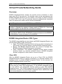
Client VPN
With the BCM50 Integrated Router set up as a Client VPN, the BCM50
Integrated Router sets up a secure connection to a corporate network via a
Contivity switch or another BCM50 Integrated Router. In this scenario, the
BCM50 Integrated Router is the Client.
Note: If the BCM50 Integrated Router is configured with the VPN Client rule, it
cannot have any other VPN configuration, i.e. the BCM50 Integrated Router
can only VPN to one designated Contivity switch or main office BCM50
Integrated Router. The Contivity switch/main office BCM50 Integrated Router
administrator provides the client BCM50 Integrated Router administrator with
basic account details to connect to their network.
6
NN40011-047 Issue 1.2 BCM50 Rls 6.0
Router - Virtual Private Networking
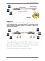
Branch VPN
The BCM50 Integrated Router Branch VPN rules allow the configuration of up
to 10 secure connections to other equivalent IPSec routers, e.g. another
BCM50 Integrated Router, over the public network. VPN connections could be
used for transferring information between PCs or setting up secure VoIP
tunnels between handsets.
When configuring Branch rules, settings must be agreed upon before
configuration can successfully take place. These settings include security
details (IKE, VPN Protocol, Pre-Shared Key), and manually entered
information such as WAN IP Addresses, Local/Remote IP Addresses, Content
Type etc. The information must match on both the local and remote ends
otherwise the connection will not be successfully made.
A worked example configuration is provided later in this guide.
NN40011-047 Issue 1.2 BCM50 Rls 6.0
7
Router – Virtual Private Networking
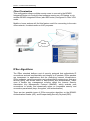
Client Termination
This configuration allows multiple remote users to connect to the BCM50
Integrated Router via Contivity client software running on a PC/laptop, or via
another BCM50 Integrated Router (also BSR router) configured in Client VPN
mode.
Mobile or home workers will find this feature useful for connecting to the main
office network, for data transfer or VoIP purposes.
IPSec Algorithms
The IPSec standard defines a set of security protocols that authenticate IP
connections and add confidentiality and integrity to IP packets. IPSec packets
are transparent to applications and the underlying network infrastructure.
IPSec supports various encryption and authentication protocols so that your
security policy can dictate levels of data privacy and authentication. IPSec
uses a flexible key management scheme called the Internet Security
Association Key Management Protocol (ISAKMP), which enables peer
connections to quickly and dynamically agree on compatible security and
connection parameters (keys, encryption, and authentication).
There are two possible types of IPSec encryption algorithm on the BCM50:
Authentication Header (AH), and Encapsulating Security Payload (ESP).
8
NN40011-047 Issue 1.2 BCM50 Rls 6.0
Router - Virtual Private Networking
Authentication Header (AH) Protocol
In applications where confidentiality is not required, an AH can be employed
to ensure integrity. This type of implementation does not protect the
information from dissemination but will allow for verification of the integrity of
the information and authentication of the originator.
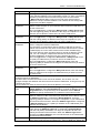
AH Protocol Options
Authentication
Description
Algorithm
MD5 (Message Digest 5)
Produces a 128-bit digest to authenticate packet data.
SHA-1 (Secure Hash
Produces a 160-bit digest to authenticate packet data.
Algorithm)
For minimal security use MD5, or for maximum security use SHA-1.
Encapsulating Security Payload
The ESP protocol provides encryption as well as some of the services offered
by AH. ESP authenticating properties are limited compared to the AH due to
the non-inclusion of the IP header information during the authentication
process. However, ESP is sufficient if only the upper layer protocols need to
be authenticated.
An added feature of the ESP is payload padding, which further protects
communications by concealing the size of the packet being transmitted.
ESP Protocol Options
Encryption Algorithm
DES (Data Encryption
Standard)
3DES (Triple DES)
Description
A widely used method of data encryption using a private (secret)
key. DES applies a 56-bit key to each 64-bit block of data.
A variant of DES, which iterates three times with three separate
keys (3 x 56 = 168 bits), effectively doubling the strength of DES.
AES (Advanced
A newer method of data encryption that also uses a secret key. This
Encryption Standard)
implementation of AES applies a 128-bit key to 128-bit blocks of
data. AES is faster than 3DES.
For minimal security use DES, or for maximum security use 3DES.
NN40011-047 Issue 1.2 BCM50 Rls 6.0
9
Router – Virtual Private Networking
VPN and NAT
Normally it is not possible to set up a VPN when there is a NAT Router in
between two VPN switches. This is because the NAT Router changes the
header of the outgoing IPSec packet so it does not match the header for
which the receiving VPN switch is checking. Therefore, the receiving VPN
switch does not respond and the tunnel cannot be built.
The BCM50 Integrated Router solves this problem by the use of NAT
Traversal; an option that can be selected when configuring VPN Branch rules.
Both VPN switches should have NAT Traversal enabled.
Note: For NAT Traversal to be successful, the VPN Branch rule should be
configured to use the ESP algorithm and also to use tunnel mode.
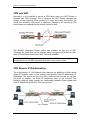
VPN Branch IP Relationships
The configuration of VPN Branch rules requires the definition of both global
(WAN IP address used on the Internet) and private (LAN IP addresses) IP
Addresses. The reason for this is so that a path can be securely set up from
one LAN to another, via WAN IP addresses used on the internet. The
following diagram helps explain the relationship between these global and
LAN IP addresses involved in VPN connections.
10
NN40011-047 Issue 1.2 BCM50 Rls 6.0
Router - Virtual Private Networking
The above diagram shows the information required for the VPN Branch setup
from switch A’s perspective:
“My” IP Address is the WAN IP address issued by the ISP (Internet
Service Provider) to switch A
Secure Gateway Address is the WAN IP address issued by the ISP to
switch B
Local IP Address Range is the range of IP Addresses used on the LAN
connected to switch A
Remote IP Address Range is the range of IP Addresses used on the
LAN connected to switch B
If a PC on switch A requests information from a PC on switch B, switch A will
initiate a VPN connection via switch B’s Secure gateway Address. Therefore,
the two LANs can communicate via the global (WAN) IP addresses specified.
From switch B’s perspective, the set information is the same but the
terminology is reversed, i.e. switch A’s “My” IP address becomes switch B’s
Secure Gateway Address and switch A’s Local IP Address Range becomes
switch B’s Remote IP Address Range etc.
Content ID & Type
Content ID and Type are extra security features that act as extra levels of
security for incoming VPN requests. They do not replace any of the possible
encryption methods (ESP, AH).
The options for type are:
IP – IP address of a computer or BCM50 Integrated Router router
Domain (DNS) – A designated domain name
E-mail – A designated e-mail address
Note: The Domain name and e-mail options do not have to actually exist and
are purely referential.
When using this feature, both local and remote (peer) Content ID and Type
will have to be specified and mirrored for either end of the VPN connection.
For example, referring back to the diagram in the VPN Branch Relationships
section, the Content ID and Type fields on switches A and B could be as
follows:
Field
Local ID Type
Content
Peer ID Type
Content
Switch A
E-mail
[email protected]
DNS
www.iteluk.com
Switch B
DNS
www.iteluk.com
E-mail
[email protected]
This information has to be agreed by the BCM switch administrators of both
BCM50 Integrated Router switches.
NN40011-047 Issue 1.2 BCM50 Rls 6.0
11
Router – Virtual Private Networking
Required Information
Before configuring IPSec, the following information is required:
What is the required level of encryption to be used?
What is the password to be used for the Pre-shared key?
What Content ID and Type will be used?
What are the WAN IP addresses of the local and remote BCM50
Integrated Router’s?
What are the LAN IP addresses of the local and remote LANs?
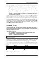
Flowchart
The flow chart below shows which sections of the guide you should use when
configuring VPN connections.
Which type of VPN do you need to configure
for the BCM50 Integrated Router?
A single connection to a
Contivity switch or another
BCM50 Integrated Router
Client Termination for remote users
using Contivity Client software or a
1100 series IP phone
Multiple VPN connections
to other BCM50 Integrated
Routers
Refer to the Client
Rule section of
this guide.
Refer to the Branch
Rule section of this
guide.
Refer to the Client
Termination section
of this guide.
Do you want to set up
exclusive access for
just one device to use
the VPN connection?
No
Yes
Refer to the
Exclusive Mode for
Client Rules section
of this guide.
Check that the VPN connections are
successfully connected: Refer to the
SA Monitor section of this guide.
12
NN40011-047 Issue 1.2 BCM50 Rls 6.0
Router - Virtual Private Networking
Accessing the Web Router GUI
There are two methods of accessing the Web Router GUI, independent on
which model you are configuring:
Via Element Manager (management application for all BCM50 models)
Directly from a web browser
From Element Manager
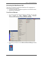
1. To access the Business Element Manager application from the Start
Menu,
navigate
to
Start,
Programs,
Avaya,
Business
Communications Manager, Business Element Manager.
2. Alternatively, double-click on the Business Element Manager desktop
icon.
NN40011-047 Issue 1.2 BCM50 Rls 6.0
13
Router – Virtual Private Networking
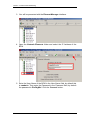
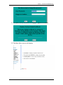
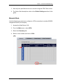
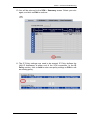
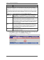
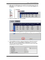
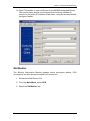
3. You will be presented with the Element Manager interface.
4. Open the Network Elements folder and select the IP Address of the
BCM.
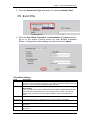
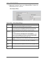
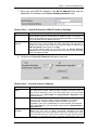
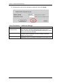
5. Enter the User Name of the BCM in the User Name field, by default this
is nnadmin. Then enter the Password in the Password field, by default
the password is PlsChgMe!. Click the Connect button.
14
NN40011-047 Issue 1.2 BCM50 Rls 6.0
Router - Virtual Private Networking
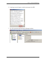
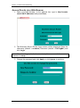
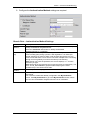
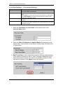
6. A warning screen will appear, read the warning and click OK.
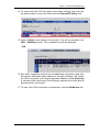
7. You will be presented with the Element Manager interface.
NN40011-047 Issue 1.2 BCM50 Rls 6.0
15
Router – Virtual Private Networking
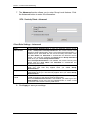
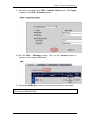
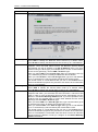
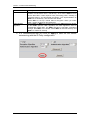
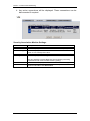
8. Click the Data Services link, select the Router link and click the
Launch Router Web GUI Tool button.
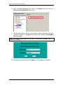
9. The Business Secure Router logon screen will be displayed. Enter the
Username (default = nnadmin) and Password (default = PlsChgMe!)
and click Login.
Note: if the above logon details do not work, try Username = admin, and
Password = setup.
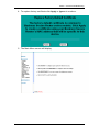
10. Change the password and click Apply, or click Ignore to continue.
16
NN40011-047 Issue 1.2 BCM50 Rls 6.0
Router - Virtual Private Networking
11. To replace factory certificate click Apply or Ignore to continue.
12. The Main Menu screen will display.
NN40011-047 Issue 1.2 BCM50 Rls 6.0
17
Router – Virtual Private Networking
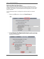
Access Directly via a Web Browser
1. Open your web browser. In the address bar, type in http://<router
card LAN IP Address>/ and press Enter.
2. The Business Secure Router logon screen will be displayed. Enter the
Username (default = nnadmin) Password (default = PlsChgMe!) and
click Login.
Note: if the above logon details do not work, try Username = admin
Password = setup.
3. Change the password and click Apply, or click Ignore to continue.
18
NN40011-047 Issue 1.2 BCM50 Rls 6.0
Router - Virtual Private Networking
4. To replace factory certificate click Apply or Ignore to continue.
5. The Main Menu screen will display.
NN40011-047 Issue 1.2 BCM50 Rls 6.0
19
Router – Virtual Private Networking
VPN Configuration
VPN & RIP
To ensure that data traffic routes correctly between the WAN interface and
devices connected to the LAN, you should ensure that RIP is enabled on the
LAN and any IP Alias interfaces. Refer to the Router – IP Routing Guide for
instructions on enabling RIP on the LAN interfaces.
Client Rule
Use the following procedure to configure a single simple rule to connect to a
BCM50 Integrated Router to a Contivity switch or another BCM50 Integrated
Router configured to allow Client Termination (refer to the Client Termination
section of this guide for more information). You will require logon details from
the Contivity switch administrator before performing this configuration.
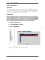
1. Access the Web Router GUI.
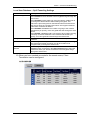
2. From the Main Menu, select VPN.
3. Select the Summary tab.
4. Select a spare rule number and click on Edit.
20
NN40011-047 Issue 1.2 BCM50 Rls 6.0
Router - Virtual Private Networking
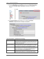
5. From the Connection Type drop down list, select Contivity Client.
6. Enter the User Name, Password, and Destination IP Address used to
log on to the remote Contivity switch (or other BCM50 Integrated
Router). Configure the other settings as required and click Apply.
Client Rule Settings
Field
Active
Description
Description
Select this check box to turn on this rule. Clear this check box if you do not
want to use this rule after you apply it. If you want to set the Contivity Client rule
to active, you must set all other VPN rules to inactive
Select this check box to turn on the Keep Alive feature for this SA (Security
Association).
Turn on Keep Alive to have the Business Secure Router automatically reinitiate
the SA after the SA lifetime times out, even if there is no traffic. The remote
IPSec router must also have keep alive enabled in order for this feature to
work.
Enter a brief description about this rule for identification purposes.
Destination
This field specifies the IP address of the remote Contivity VPN switch.
User Name
Enter the user name exactly as the remote Contivity VPN switch administrator
gives you.
Enter the password exactly as the remote Contivity VPN switch administrator
gives you.
Keep Alive
Password
NN40011-047 Issue 1.2 BCM50 Rls 6.0
21
Router – Virtual Private Networking
7. The Advanced section allows you to enter Group Level features. Click
the Advanced button to enter this information.
Client Rule Settings - Advanced
Field
Group
Authentication
Group ID
Group Password
On Demand Client
Tunnel
Description
Enable Group Authentication to have the Business Secure Router
sends, a Group ID and Group Password to the remote Contivity VPN
switch for initial authentication. After a successful initial authentication, a
RADIUS server associated with the remote Contivity VPN switch uses
the User Name and Password to authenticate the Business Secure
Router. You must also configure the Group ID and Group Password
fields when you enable Group Authentication.
When Group Authentication is not enabled, the remote Contivity VPN
switch uses the User Name and Password to authenticate the
Business Secure Router.
Enter the group ID exactly as the Contivity VPN switch administrator
gives you. This field only applies when you enable Group
Authentication.
Enter the group password exactly as the Contivity VPN switch
administrator gives you. This field only applies when you enable Group
Authentication.
Select this check box to have any outgoing packets automatically trigger
a VPN connection to the remote Contivity VPN switch.
When On Demand Client Tunnel is not enabled, you need to go to the
VPN Summary screen and click the Connect button to create a VPN
connection to the remote Contivity VPN switch.
8. Click Apply to save your settings.
22
NN40011-047 Issue 1.2 BCM50 Rls 6.0
Router - Virtual Private Networking
9. You will be returned to the VPN – Contivity Client screen. Click Apply
to return to the VPN – Summary screen.
10. On the VPN – Summary screen, click on the Connect button to
connect to the remote VPN switch.
11. Check the SA Monitor screen to see if the connection is successful.
Note: On configuring the Client Rule, it will not be possible to configure any
other Client or Branch Rules.
NN40011-047 Issue 1.2 BCM50 Rls 6.0
23
Router – Virtual Private Networking
Exclusive Mode for Client Rules
When configuring the BCM50 Integrated Router as a VPN Client, you can
configure an exclusive mode for one of your network devices such as a PC or
IP Phone. This results in only that network device being able to use the VPN
Client connection.
Use the following process to configure the exclusive mode for a network
device.
1. Whilst in the VPN section, click on the Global Setting tab.
2. Tick the Exclusive Use Mode for Client Tunnel checkbox, and enter
the MAC Address of the device that you want to use the VPN Client
connection for exclusively.
24
NN40011-047 Issue 1.2 BCM50 Rls 6.0
Router - Virtual Private Networking
3. Now only the specified device can connect using the VPN Client tunnel.
4. For further field descriptions refer to the Global Settings section of this
guide.
Branch Rule
Use the following procedure to configure a VPN connection to another BCM50
Integrated Router (for example).
1. Access the Web Router GUI.
2. From the Main menu, select VPN.
3. Select the Summary tab.
4. Select a rule number and click on Edit.
NN40011-047 Issue 1.2 BCM50 Rls 6.0
25
Router – Virtual Private Networking
5. Ensure the Connection Type is set to Branch Office. Configure the
IPSec Setup settings as required.
Branch Rule – IP Sec Setup Settings
Field
Active
IPSec Key
Management
Description
Select this check box to turn on this rule. Clear this check box if you do not
want to use this rule after you apply it. If you want to set the Contivity Client
rule to active, you must set all other VPN rules to inactive
Select this check box to turn on the nailed up feature for this SA.
Turn on nailed up to have the BCM50e Integrated Router automatically
reinitiate the SA after the SA lifetime times out, even if there is no traffic. The
BCM50e Integrated Router also reinitiates the SA when it restarts.
Select this check box to enable NAT traversal. With NAT traversal, you can
set up a VPN connection when there are NAT routers between the two VPN
switches.
The remote VPN switch must also have NAT traversal enabled.
You can use NAT traversal with ESP protocol using Transport or Tunnel
mode, but not with AH protocol. In order for a VPN switch behind a NAT
router to receive an initiating IPSec packet, set the NAT router to forward
UDP port 500 to the VPN switch behind the NAT router.
Type up to 32 characters to identify this VPN policy. You may use any
character, including spaces, but the Business Secure Router drops trailing
spaces
Select IKE or Manual from the drop-down list box. Manual is a useful option
for troubleshooting if you have problems using IKE key management.
Negotiation
Mode
Select Main or Aggressive from the drop-down list box. Multiple SAs
connecting through a secure gateway must have the same negotiation mode.
Encapsulation
Mode
Select Tunnel mode or Transport mode from the drop-down list box.
Nailed Up
NAT
Traversal
Name
26
NN40011-047 Issue 1.2 BCM50 Rls 6.0
Router - Virtual Private Networking
6. Configure the Authentication Method settings as required.
Branch Rule – Authentication Method Settings
Field
Authentication
Method
Pre-Shared
Key
Retype to
Confirm
Certificate
Description
Select the Pre-Shared Key radio button to use a preshared secret key to
identify the BCM50e Integrated Router.
Select the Certificate radio button to identify the BCM50e
Integrated Router by a certificate.
Type your pre-shared key in this field. A pre-shared key identifies a
communicating party during a phase 1 IKE negotiation. It is called "preshared" because you have to share it with another party before you can
communicate with them over a secure connection. Multiple SA’s connecting
through a secure gateway must have the same pre-shared key.
Note: that as you enter the password, the screen displays a "*" for each
character you type.
Note: Both ends of the VPN tunnel must use the same pre-shared key. You
see a “PYLD_MALFORMED” (payload malformed) log if the same
preshared key is not used on both ends.
Enter the pre-shared key again for confirmation.
Use the drop-down list box to select the certificate to use for this
VPN tunnel.
You must have certificates already configured in the My Certificates
screen. Click My Certificates to go to the My Certificates screen, where
you can view the BCM50e Integrated Router's list of certificates.
NN40011-047 Issue 1.2 BCM50 Rls 6.0
27
Router – Virtual Private Networking
Field
Description
Local ID Type
Select IP to identify this Business Secure Router by its IP address.
Select DNS to identify this Business Secure Router by a domain name.
Select E-mail to identify this Business Secure Router by an e-mail address.
When you select IP in the Local ID Type field, type the IP address of your
computer. Leave this field blank to have the Business Secure Router
automatically use the IP address in the My IP Address field. If you have
problems using the IP ID type (for example there is a NAT router between
the two secure gateways), use the DNS or E-mail ID type.
When you select DNS in the Local ID Type field, type a domain name (up
to 31 characters) by which to identify this Business Secure Router.
When you select E-mail in the Local ID Type field, type an e-mail address
(up to 31 characters) by which to identify this Business Secure Router.
The domain name or e-mail address that you use in the Content field is
used for identification purposes only and does not need to be a real domain
name or e-mail address.
Select IP to identify the remote IPSec router by its IP address.
Select DNS to identify the remote IPSec router by a domain name.
Select E-mail to identify the remote IPSec router by an e-mail address.
When you select IP in the Peer ID Type field, type the IP address of the
computer with which you will make the VPN connection. Leave this field
blank in order to have the Business Secure Router automatically use the
address in the Secure Gateway Address field. If you have problems using
the IP ID type (for example there is a NAT router between the two secure
gateways), use the DNS or E-mail ID type.
When you select DNS in the Peer ID Type field, type a domain name (up to
31 characters) by which to identify the remote IPSec router.
When you select E-mail in the Peer ID Type field, type an e-mail address
(up to 31 characters) by which to identify the remote IPSec router.
The domain name or e-mail address that you use in the Content field is
used for identification purposes only and does not need to be a real domain
name or e-mail address. The domain name also does not have to match the
remote router's IP address or what you configure in the Secure Gateway
Address field below.
Content
Peer ID Type
Content
28
NN40011-047 Issue 1.2 BCM50 Rls 6.0
Router - Virtual Private Networking
7. Enter your own WAN IP Address in the My IP Address field, and the
destination IP Address in the Secure Gateway Address field.
Branch Rule - Local & Destination WAN IP Address Settings
Field
My IP Address
Secure Gateway
Address
Description
Enter the WAN IP address of your Business Secure Router. The Business
Secure Router uses its current WAN IP address (static or dynamic) in
setting up the VPN tunnel if you leave this field as 0.0.0.0. The VPN tunnel
has to be rebuilt if this IP address changes.
Type the WAN IP address or the URL (up to 31 characters) of the IPSec
router with which you're making the VPN connection. Set this field to
0.0.0.0 if the remote IPSec router has a dynamic WAN IP address (the
IPSec Key Mode field must be set to IKE).
The remote address fields do not apply when the Secure Gateway
Address field is configured to 0.0.0.0. In this case only the remote IPSec
router can initiate the VPN.
8. Configure the Security Protocol settings as required.
Branch Rule – Security Protocol Settings
Field
VPN Protocol
(ESP)
AH
Encryption
Algorithm
Description
Select ESP if you want to use ESP (Encapsulation Security Payload).
The ESP protocol (RFC 2406) provides encryption as well as some of
the services offered by AH. If you select ESP here, you must select
options from the VPN Setup and Authentication Algorithm fields
(described next).
Select AH if you want to use AH (Authentication Header
Protocol). The AH protocol (RFC 2402) was designed for integrity,
authentication, sequence integrity (replay resistance), and nonrepudiation, but not for confidentiality, for which the ESP was designed.
If you select AH here, you must select options from the Authentication
Algorithm field.
Select DES, 3DES, AES or NULL from the drop-down list box.
When you use one of these encryption algorithms for data
communications, both the sending device and the receiving device must
use the same secret key, which can be used to encrypt and decrypt the
message or to generate and verify a message authentication code. The
NN40011-047 Issue 1.2 BCM50 Rls 6.0
29
Router – Virtual Private Networking
Field
Authentication
Algorithm
Description
DES encryption algorithm uses a 56-bit key. Triple DES (3DES) is a
variation on DES that uses a 168-bit key. As a result, 3DES is more
secure than DES. It also requires more processing power, resulting in
increased latency and decreased throughput. This implementation of
AES uses a 128-bit key. AES is faster than 3DES.
Select NULL to set up a tunnel without encryption. When you select
NULL, you do not enter an encryption key.
Select SHA1 or MD5 from the drop-down list box. MD5 (Message Digest
5) and SHA1 (Secure Hash Algorithm) are hash algorithms used to
authenticate packet data. The SHA1 algorithm is generally considered
stronger than MD5, but is slower. Select MD5 for minimal security and
SHA-1 for maximum security
9. It is recommended that you click on Apply to save the rule before
commencing with the IP Policy configuration.
30
NN40011-047 Issue 1.2 BCM50 Rls 6.0
Router - Virtual Private Networking
10. You will be returned to the VPN – Summary screen. Select your rule
again, and click on Edit to continue.
11. The IP Policy settings now need to be entered. IP Policy defines the
LAN IP Addresses at either end of the VPN connection. In the IP
Policy section, click on Add to enter new policy settings or Edit to edit
an existing policy.
NN40011-047 Issue 1.2 BCM50 Rls 6.0
31
Router – Virtual Private Networking
12. Enter the Local and Remote LAN IP Address information as required.
Branch Rule – IP Policy Settings
Field
Description
Protocol
Enter 1 for ICMP, 6 for TCP, 17 for UDP, etc. 0 is the default and signifies
any protocol.
If you specify a protocol other than 1 (ICMP) or 0 (any protocol), you
cannot use the control ping feature.
Select the check box and configure an IP address in the Control
Enable Control
Ping IP Address field to have the BCM50e Integrated Router periodically
Ping
test the VPN tunnel to the branch office.
The BCM50e Integrated Router pings the IP address every minute. The
BCM50e Integrated Router starts the IPSec connection idle timeout timer
when it sends the ping packet. If there is no traffic from the remote VPN
switch by the time the timeout period expires, the BCM50e Integrated
Router disconnects the VPN tunnel.
Branch Tunnel NAT Address Mapping Rule
Active
Type
32
Enable this feature to have the Business Secure Router use a different
(virtual) IP address for the VPN connection. When you enable branch
tunnel NAT address mapping, you do not configure the local section.
Select one of the following port mapping types.
1. One-to-One: One-to-one mode maps one private IP address to one
virtual IP address. Port numbers do not change with one-to-one NAT
mapping.
NN40011-047 Issue 1.2 BCM50 Rls 6.0
Router - Virtual Private Networking
Field
Description
2. Many-to-One: Many-to-One mode maps multiple private IP addresses
to one virtual IP address. This is equivalent to SUA (i.e., PAT, port address
translation), Business Secure Router's Single User Account feature.
3. Many One-to-one: Many One-to-one mode maps each private IP
address to a unique virtual IP address. Port numbers do not change with
many one-to-one NAT mapping.
When the Type field is configured to One-to-one, enter the (static) IP
Private Starting
IP Address
address of the computer on your Business Secure Router's LAN that is to
use the VPN tunnel.
When the Type field is configured to Many-to-One or Many One-to-one,
enter the beginning (static) IP address of the range of computers on your
Business Secure Router's LAN that are to use the VPN tunnel.
When the Type field is configured to One-to-one, this field is N/A.
Private Ending
When the Type field is configured to Many-to-One or Many One-to-one,
IP Address
enter the ending (static) IP address of the range of computers on your
Business Secure Router's LAN that are to use the VPN tunnel.
Virtual Starting
Virtual addresses must be static and correspond to the remote IPSec
IP Address
router's configured remote IP addresses.
The computers on the Business Secure Router's LAN and the remote
network can function as if they were on the same subnet when the virtual
IP address(es) are on the same subnet as the remote IP address(es).
Two active SAs can have the same virtual or remote IP address, but not
both. You can configure multiple SAs between the same virtual and
remote IP addresses, as long as only one is active at any time.
When the Type field is configured to One-to-one or Many-to-One, enter
the (static) IP address that you want to use for the VPN tunnel.
When the Type field is configured to Many One-to-one, enter the
beginning (static) IP address of the range of IP addresses that you want to
use for the VPN tunnel.
When the Type field is configured to One-to-one or Many-to-One, this
Virtual Ending
IP Address
field is N/A.
When the Type field is configured to Many One-to-one, enter the ending
(static) IP address of the range of IP addresses that you want to use for
the VPN tunnel.
Local: Local IP addresses must be static and correspond to the remote IPSec router's
configured remote IP addresses.
Two active SAs can have the same local or remote IP address, but not both. You can
configure multiple SAs between the same local and remote IP addresses, as long as only one
is active at any time.
Two IP policies can have the same local or remote IP address, but not both.
Use the drop-down menu to choose Single Address, Range Address, or
Local Address
Subnet Address. Select Single Address for a single IP address. Select
Type
Range Address for a specific range of IP addresses. Select Subnet
Address to specify IP addresses on a network by their subnet mask.
IP Address Start When the Address Type field is configured to Single Address, enter a
(static) IP address on the LAN behind your Business Secure Router. When
the Address Type field is configured to Range Address, enter the
beginning (static) IP address, in a range of computers on your LAN behind
your Business Secure Router. When the Address Type field is configured
to Subnet Address, this is a (static) IP address on the LAN behind your
Business Secure Router.
When the Address Type field is configured to Single Address, this field
End / Subnet
is N/A. When the Address Type field is configured to Range Address,
Mask
enter the end (static) IP address, in a range of computers on the LAN
behind your Business Secure Router. When the Address Type field is
configured to Subnet Address, this is a subnet mask on the LAN behind
your Business Secure Router.
Local StartPort
0 is the default and signifies any port. Type a port number from 0 to 65535.
Some of the most common IP ports are: 21, FTP; 53, DNS; 23, Telnet; 80,
NN40011-047 Issue 1.2 BCM50 Rls 6.0
33
Router – Virtual Private Networking
Field
Description
HTTP; 25, SMTP; 110, POP3
Remote: Remote IP addresses must be static and correspond to the remote IPSec router's
configured local IP addresses. The remote fields do not apply when the Secure Gateway
Address field is configured to 0.0.0.0. In this case only the remote IPSec router can initiate the
VPN.
Two active SAs cannot have the local and remote IP address(es) both the same. Two active
SAs can have the same local or remote IP address, but not both. You can configure multiple
SAs between the same local and remote IP addresses, as long as only one is active at any
time.
Two IP policies can have the same local or remote IP address, but not both.
Use the drop-down menu to choose Single Address, Range Address, or
Remote
Subnet Address. Select Single Address for a single IP address. Select
Address Type
Range Address for a specific range of IP addresses. Select Subnet
Address to specify IP addresses on a network by their subnet mask.
IP Address Start When the Address Type field is configured to Single Address, enter a
(static) IP address on the LAN behind your Business Secure Router. When
the Address Type field is configured to Range Address, enter the
beginning (static) IP address, in a range of computers on your LAN behind
your Business Secure Router. When the Address Type field is configured
to Subnet Address, this is a (static) IP address on the LAN behind your
Business Secure Router.
End / Subnet
When the Address Type field is configured to Single Address, this field is
Mask
N/A. When the Address Type field is configured to Range Address, enter
the end (static) IP address, in a range of computers on the LAN behind
your Business Secure Router. When the Address Type field is configured
to Subnet Address, this is a subnet mask on the LAN behind your
Business Secure Router.
Remote Start
0 is the default and signifies any port. Type a port number from 0 to 65535.
Port
Some of the most common IP ports are: 21, FTP; 53, DNS; 23, Telnet; 80,
HTTP; 25, SMTP; 110, POP3
13. Click Apply to save your changes. The IP Policy you have just
configured will appear in the Available IP Policy area.
34
NN40011-047 Issue 1.2 BCM50 Rls 6.0
Router - Virtual Private Networking
14. To ensure that the VPN connection uses these settings, you must use
the down arrows to move the Policy into the Selected IP Policy area.
15. Click on Apply at the bottom of the screen. You will be returned to the
VPN – Summary screen. The completed rule will be displayed.
16. Any traffic originating within the local addresses requesting data from
the remote addresses which adhere to the policy settings, will initiate
the VPN connection to the Secure gateway Address (unless Nailed up
is selected within the Branch Rule settings, whereby the tunnel should
be permanently connected).
17. To view if the VPN connection is operational, view the SA Monitor tab.
NN40011-047 Issue 1.2 BCM50 Rls 6.0
35
Router – Virtual Private Networking
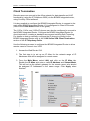
Client Termination
Remote users can connect to the office network for data transfer and VoIP
functionality (using the IP Softphone 2050) via the BCM50 Integrated router,
using Contivity Client software.
It is also possible to configure the BCM50 Integrated Router to connect to the
main office BCM50 Integrated Router, if it is configured in Client VPN mode
(refer to the Client Rule section of this guide).
The 1120e, 1140e, and 1150e IP phones can also be configured to connect to
the BCM50 Integrated Router. Configure the BCM50 Integrated Router for
client termination, creating a standard user account omitting Split Tunneling.
For details on how to manually configure the IP phone to connect to the
BCM50 Integrated Router refer to the 1100 Series VPN Client Termination
section of the IP Telephony Guide.
Use the following process to configure the BCM50 Integrated Router to allow
remote users to connect via a VPN.
1. Access the Web Router GUI.
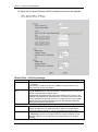
2. The first step is to set up an IP Alias for the network range of IP
Addresses that will be assigned to remote users.
3. From the Main Menu, select LAN, and click on the IP Alias tab.
Enable the IP Alias and enter a valid IP Address and Subnet Mask.
This will act as the default gateway for the remote users, who should
be assigned IP Addresses in the same range. Click Apply when
finished.
36
NN40011-047 Issue 1.2 BCM50 Rls 6.0
Router - Virtual Private Networking
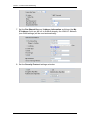
4. Next, account details have to be created for the remote users. From the
Main Menu, select Auth Server. Ensure the Local User Database tab
is selected.
5. Select an available entry, and click Edit.
6. Tick the Active checkbox to activate this account. Select the required
User Type, and give a User Name and Password for this account.
The User Name and Password will be used by the remote users when
configuring the Contivity software.
NN40011-047 Issue 1.2 BCM50 Rls 6.0
37
Router – Virtual Private Networking
Local User Database – User account Settings
Field
Desctiption
Active
Select this check box to turn on the user account. Clear this check
box to turn off the user account.
Select 802.1X to set this user account to be used for a IEEE 802.1X
login.
Select IPSec to set this user account to be used for an IPSec login.
Select 802.1X/IPSec to set this user account to be used for both
IEEE 802.1X and IPSec logins.
Specify the user ID to be used as the login name for the user
account.
Enter a password up to 31 characters long for this user account.
Note that as you type a password, the screen displays a (*) for each
character you type.
User Type
User Name
Password
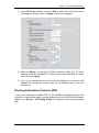
7. Enter the First Name and Last Name of the remote user in the
Account Name fields.
8. Enter the Static IP Address and Subnet Mask to be assigned to the
remote user. This should be of the same network range created for the
IP Alias earlier.
9. Split Tunneling can be configured if required, although understanding
of the feature is required to do so. (Split Tunneling enables the use of
other networks the remote user may be connected to whilst the VPN
connection is active). Click Apply to save the account.
38
NN40011-047 Issue 1.2 BCM50 Rls 6.0
Router - Virtual Private Networking
Local User Database – Split Tunneling Settings
Field
Desctiption
Split Tunneling
Enable or disable split tunneling or inverse split tunneling.
Select Disable to force all traffic to be encrypted and go through the
VPN tunnel.
Select Enabled to allow traffic not going through the VPN tunnel to
go through the WAN interface without being encrypted. This
reduces the processing load on the Business Secure Router but is
less secure since the Contivity VPN clients’ unencrypted sessions
make them vulnerable to attacks.
Select Enabled - Inverse to force traffic not going to the network
subnets that you specify, to be encrypted and sent through the VPN
tunnel.
Select Enable - Inverse (locally connected) to force traffic not going
to directly connected networks or the network subnets that you
specify, to be encrypted and sent through the VPN tunnel.
Click this link to set up the list of networks to use as split or inverse
networks.
This field applies when you select Enabled in the Split Tunneling
field. Select the network for which you will force traffic to be
encrypted and go through the VPN tunnel.
This field applies when you select Enabled - Inverse or Enabled Inverse (locally connected) in the Split Tunneling field. Select the
network for which you will not force traffic to be encrypted and go
through the VPN tunnel.
Configure Network
Split Tunnel Networks
Inverse Split Tunnel
Network
10. When you have created accounts for the remote users, Client
Termination can be configured.
NN40011-047 Issue 1.2 BCM50 Rls 6.0
39
Router – Virtual Private Networking
11. From the Main Menu, select VPN and click on the Client Termination
tab. Tick the Enable Client Termination checkbox to enable this
feature.
12. The Authentication options allow you to use the Local User
Database configured earlier. Configure as required.
Client Termination –Authentication Settings
Field
Desctiption
Local User Database
Select this option to have the Business Secure Router use its
internal list of users to authenticate the Contivity VPN clients. Click
Configure Local User Database to edit the list of users and their
user names and passwords.
Select this option to have the Business Secure Router use the
Contivity VPN clients’ user names and passwords as a pre-shared
key to identify them during phase 1 IKE negotiations. The remote
users will have to configure the Contivity Software accordingly.
Select this option to have the Business Secure Router use an
external RADIUS server to identify the Contivity VPN clients during
phase 1 IKE negotiations. Click Configure RADIUS Server to
specify the associated external RADIUS server.
The Contivity VPN clients send the group ID and group password to
the Business Secure Router for or initial authentication. After a
successful initial authentication, the associated external RADIUS
User Name and
Password/Pre-Shared
Key
RADIUS Server
Group ID
40
NN40011-047 Issue 1.2 BCM50 Rls 6.0
Router - Virtual Private Networking
Field
Desctiption
Group Password
server uses the Contivity VPN client’s user name and password to
authenticate the Contivity VPN client.
Enter a group ID of up to 31 ASCII characters.
Enter a group password of up to 31 ASCII characters. Enter it a
second time to make sure you have entered it correctly.
Select User Name and Password to have the external RADIUS
server use the Contivity VPN clients’ user names and passwords to
authenticate them during phase 1 IKE negotiations.
Authentication Type
13. Select all the Encryption options the remote user might be using.
14. Determine how the remote user is assigned an IP Address. You can
use the Static Addresses configured when setting up the Local User
Accounts earlier, or Configure IP Address Pools for dynamic
assignment.
NN40011-047 Issue 1.2 BCM50 Rls 6.0
41
Router – Virtual Private Networking
15. Configure the rest of the settings as required, and click Apply.
Client Termination – Additional Settings
Field
Desctiption
Enable Perfect
Forward Secrecy
Perfect Forward Secrecy (PFS) is disabled by default in phase 2
IPSec SA setup. This allows faster IPSec setup, but is not so
secure. Turn on PFS to use the Diffie-Hellman exchange to create a
new key for each IPSec SA setup.
Set the allowed lifetime for an individual key used for data
encryption before negotiating a new key. A setting of 00:00:00
disables the rekey timeout.
Set how much data can be transmitted via the VPN tunnel before
negotiating a new key. A setting of 0 disables the rekey data count.
Rekey Timeout
Rekey Data Count
42
NN40011-047 Issue 1.2 BCM50 Rls 6.0
Router - Virtual Private Networking
16. Client Termination is now configured on the BCM50 Integrated Router.
The remote users should now configure their Contivity software to
connect to the public IP Address of the router, using the account details
configured earlier.
SA Monitor
The Security Association Monitor displays active connection details. VPN
connections can also be disconnected from this screen.
1. Access the Web Router GUI.
2. From the Main Menu, select VPN.
3. Select the SA Monitor tab.
NN40011-047 Issue 1.2 BCM50 Rls 6.0
43
Router – Virtual Private Networking
4. Any active connections will be displayed. These connections can be
disconnected if required.
Security Association Monitor Settings
Label
Description
#
Name
Connection Type
This is the security association index number.
This field displays the identification name for this VPN policy.
This field displays whether this is a connection to another IPSec
router or to a Contivity VPN client.
This field displays Tunnel or Transport mode.
This field displays the security protocols used for an SA.
Encapsulation
IPSec Algorithm
Refresh
Disconnect
44
Both AH and ESP increase Business Secure Router processing
requirements and communications latency (delay).
Click Refresh to display the current active VPN connection(s).
Select a security association index number that you want to
disconnect and then click Disconnect.
NN40011-047 Issue 1.2 BCM50 Rls 6.0
Router - Virtual Private Networking
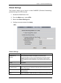
Global Settings
This section allows you to block or allow NetBIOS (Windows Networking)
packets through the VPN tunnels.
1. Access the Web Router GUI.
2. From the Main menu, select VPN.
3. Select the Global Settings tab.
4. Configure as required and click Apply.
Global Settings
Field
Desctiption
Windows Networking
(NetBIOS over
TCP/IP)
NetBIOS (Network Basic Input/Output System) are TCP or
UDP packets that enable a computer to connect to and
communicate with a LAN. It an sometimes be necessary to allow
NetBIOS packets to pass through VPN tunnels in order to allow
local computers to find computers on the remote network and vice
versa.
Allow Through IPSec
Select this check box to send NetBIOS packets through the VPN
Tunnel
connection.
Contivity Client Global Settings
Exclusive Use Mode
for Client Tunnel
MAC Address Allowed
Contivity Client FailOver
Select this check box to permit only the computer with the
MAC address that you specify to set up a VPN connection to the
remote VPN switch.
Enter the MAC address of the computer you want to allow to use
the VPN tunnel.
The Contivity Client fail-over feature allows a Contivity
client to establish a VPN connection to a backup VPN switch when
NN40011-047 Issue 1.2 BCM50 Rls 6.0
45
Router – Virtual Private Networking
Field
First Gateway
Second Gateway
Third Gateway
46
Desctiption
the default remote VPN switch (specified in the Destination field) is
not accessible.
The VPN fail-over feature must also be set up in the remote VPN
switch.
These read-only fields display the IP addresses of the backup VPN
switches. The BCM50e Integrated Router automatically gets this
information from the default remote
VPN switch.
After the remote VPN switch is unreachable or fails to
respond to IKE negotiation, the BCM50e Integrated
Router tries to establish a VPN connection to a backup
VPN switch.
NN40011-047 Issue 1.2 BCM50 Rls 6.0
Router - Virtual Private Networking
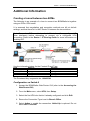
Additional Information
Creating a tunnel between two BCMs
The following is an example of a how to connect two BCM50a/ba’s together
using an IPSec VPN tunnel.
It is assumed that negotiation and encryption methods are left at default
settings, and that there isn’t a NAT Router in between the two switches.
Note: Ensure that RIP is enabled on the LAN interface (& any configured IP
Alias interfaces) before attempting to connect via a configured VPN
connection. Refer to the Router – IP Routing Guide for more information on
enabling RIP.
Use the information below for the Content ID and Type:
Field
Local ID Type
Content
Peer ID Type
Content
Switch A
E-mail
[email protected]
E-mail
[email protected]
Switch B
E-mail
[email protected]
E-mail
[email protected]
The Pre-shared Key is agreed to be: 123456789
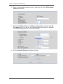
Configuration on Switch A
1. Access the BCM50a/ba Web Router GUI (refer to the Accessing the
Web Router GUI).
2. From the Main menu, select VPN, then Setup.
3. Select the first VPN rule that isn’t already configured and click Edit.
4. Ensure the Connection Type is set to Branch Office.
5. Select Active to enable the connection. Nailed Up is optional. Do not
select NAT Traversal.
NN40011-047 Issue 1.2 BCM50 Rls 6.0
47
Router – Virtual Private Networking
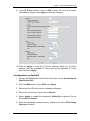
6. Enter an appropriate reference name, and keep the other IPSec Setup
Options as default.
7. Set the Pre-Shared Key and Address Information as follows (the My
IP Address field can be left to 0.0.0.0 whereby the WAN IP Address
(see WAN settings) will be used automatically):
8. Set the Security Protocol settings as below:
48
NN40011-047 Issue 1.2 BCM50 Rls 6.0
Router - Virtual Private Networking
9. In the IP Policy section, click on Add to enter the local and remote
LAN address ranges (click Apply to save the changes).
10. Click on Apply to save the IP Policy settings. Move the IP Policy
settings from the Available IP Policy area to the Selected IP Policy
area, and click Apply.
Configuration on Switch B
1. Access the BCM50a/ba Web Router GUI (refer to the Accessing the
Web Router GUI).
2. From the Main menu, select VPN, then Setup.
3. Select the first VPN rule that isn’t already configured.
4. Ensure the Connection Type is set to Branch.
5. Select Active to enable the connection. Nailed Up is optional. Do not
select NAT Traversal.
6. Enter an appropriate reference name, and keep the other IPSec Setup
Options as default.
NN40011-047 Issue 1.2 BCM50 Rls 6.0
49
Router – Virtual Private Networking
7. Set the Pre-Shared Key and Address Information as follows (the My
IP Address field can be left to 0.0.0.0 whereby the WAN IP Address
(see WAN settings) will be used automatically):
8. Set the Security Protocol settings as below:
50
NN40011-047 Issue 1.2 BCM50 Rls 6.0
Router - Virtual Private Networking
9. In the IP Policy section, click on Add to enter the local and remote
LAN address ranges (click on Apply to save the changes).
11. Click on Apply to save the IP Policy settings. Move the IP Policy
settings from the Available IP Policy area to the Selected IP Policy
area, and click Apply.
12. Try a ping command from one local LAN address to a remote LAN
address to activate the tunnel. Use the SA Monitor tab to view the
connection.
Routing Information Protocol (RIP)
It may be necessary to enable RIP on the BCM50 Integrated Router LAN
interface to ensure that data is routed between the LAN and WAN interfaces.
Refer to the Router – IP Routing Guide for information concerning enabling
RIP.
NN40011-047 Issue 1.2 BCM50 Rls 6.0
51
Router – Virtual Private Networking
Avaya Documentation Links
52
BCM50e/be Integrated Router Configuration – Basics
BCM50a/ba Integrated Router Configuration – Basics
NN40011-047 Issue 1.2 BCM50 Rls 6.0