1
Connecting ASN Routers
to a Network
BayRS Version 13.00
Site Manager Software Version 7.00
Part No. 303549-A Rev 00
October 1998
4401 Great America Parkway
Santa Clara, CA 95054
8 Federal Street
Billerica, MA 01821
Copyright © 1998 Bay Networks, Inc.
All rights reserved. Printed in the USA. October 1998.
The information in this document is subject to change without notice. The statements, configurations, technical data,
and recommendations in this document are believed to be accurate and reliable, but are presented without express or
implied warranty. Users must take full responsibility for their applications of any products specified in this document.
The information in this document is proprietary to Bay Networks, Inc.
The software described in this document is furnished under a license agreement and may only be used in accordance
with the terms of that license. A summary of the Software License is included in this document.
Trademarks
AN, BCN, BLN, BN, FRE, Optivity, PPX, and Bay Networks are registered trademarks and Advanced Remote Node,
ANH, ARN, ASN, BayRS, BaySecure, BayStack, BayStream, BCC, SPEX, System 5000, and the Bay Networks logo
are trademarks of Bay Networks, Inc.
Microsoft, MS, MS-DOS, Win32, Windows, Internet Explorer, and Windows NT are registered trademarks of
Microsoft Corporation.
All other trademarks and registered trademarks are the property of their respective owners.
Restricted Rights Legend
Use, duplication, or disclosure by the United States Government is subject to restrictions as set forth in subparagraph
(c)(1)(ii) of the Rights in Technical Data and Computer Software clause at DFARS 252.227-7013.
Notwithstanding any other license agreement that may pertain to, or accompany the delivery of, this computer
software, the rights of the United States Government regarding its use, reproduction, and disclosure are as set forth in
the Commercial Computer Software-Restricted Rights clause at FAR 52.227-19.
Statement of Conditions
In the interest of improving internal design, operational function, and/or reliability, Bay Networks, Inc. reserves the
right to make changes to the products described in this document without notice.
Bay Networks, Inc. does not assume any liability that may occur due to the use or application of the product(s) or
circuit layout(s) described herein.
Portions of the code in this software product may be Copyright © 1988, Regents of the University of California. All
rights reserved. Redistribution and use in source and binary forms of such portions are permitted, provided that the
above copyright notice and this paragraph are duplicated in all such forms and that any documentation, advertising
materials, and other materials related to such distribution and use acknowledge that such portions of the software were
developed by the University of California, Berkeley. The name of the University may not be used to endorse or
promote products derived from such portions of the software without specific prior written permission.
SUCH PORTIONS OF THE SOFTWARE ARE PROVIDED “AS IS” AND WITHOUT ANY EXPRESS OR
IMPLIED WARRANTIES, INCLUDING, WITHOUT LIMITATION, THE IMPLIED WARRANTIES OF
MERCHANTABILITY AND FITNESS FOR A PARTICULAR PURPOSE.
In addition, the program and information contained herein are licensed only pursuant to a license agreement that
contains restrictions on use and disclosure (that may incorporate by reference certain limitations and notices imposed
by third parties).
ii
303549-A Rev 00
Bay Networks, Inc. Software License Agreement
NOTICE: Please carefully read this license agreement before copying or using the accompanying software or
installing the hardware unit with pre-enabled software (each of which is referred to as “Software” in this Agreement).
BY COPYING OR USING THE SOFTWARE, YOU ACCEPT ALL OF THE TERMS AND CONDITIONS OF
THIS LICENSE AGREEMENT. THE TERMS EXPRESSED IN THIS AGREEMENT ARE THE ONLY TERMS
UNDER WHICH BAY NETWORKS WILL PERMIT YOU TO USE THE SOFTWARE. If you do not accept these
terms and conditions, return the product, unused and in the original shipping container, within 30 days of purchase to
obtain a credit for the full purchase price.
1. License Grant. Bay Networks, Inc. (“Bay Networks”) grants the end user of the Software (“Licensee”) a personal,
nonexclusive, nontransferable license: a) to use the Software either on a single computer or, if applicable, on a single
authorized device identified by host ID, for which it was originally acquired; b) to copy the Software solely for backup
purposes in support of authorized use of the Software; and c) to use and copy the associated user manual solely in
support of authorized use of the Software by Licensee. This license applies to the Software only and does not extend
to Bay Networks Agent software or other Bay Networks software products. Bay Networks Agent software or other
Bay Networks software products are licensed for use under the terms of the applicable Bay Networks, Inc. Software
License Agreement that accompanies such software and upon payment by the end user of the applicable license fees
for such software.
2. Restrictions on use; reservation of rights. The Software and user manuals are protected under copyright laws.
Bay Networks and/or its licensors retain all title and ownership in both the Software and user manuals, including any
revisions made by Bay Networks or its licensors. The copyright notice must be reproduced and included with any
copy of any portion of the Software or user manuals. Licensee may not modify, translate, decompile, disassemble, use
for any competitive analysis, reverse engineer, distribute, or create derivative works from the Software or user manuals
or any copy, in whole or in part. Except as expressly provided in this Agreement, Licensee may not copy or transfer
the Software or user manuals, in whole or in part. The Software and user manuals embody Bay Networks’ and its
licensors’ confidential and proprietary intellectual property. Licensee shall not sublicense, assign, or otherwise
disclose to any third party the Software, or any information about the operation, design, performance, or
implementation of the Software and user manuals that is confidential to Bay Networks and its licensors; however,
Licensee may grant permission to its consultants, subcontractors, and agents to use the Software at Licensee’s facility,
provided they have agreed to use the Software only in accordance with the terms of this license.
3. Limited warranty. Bay Networks warrants each item of Software, as delivered by Bay Networks and properly
installed and operated on Bay Networks hardware or other equipment it is originally licensed for, to function
substantially as described in its accompanying user manual during its warranty period, which begins on the date
Software is first shipped to Licensee. If any item of Software fails to so function during its warranty period, as the sole
remedy Bay Networks will at its discretion provide a suitable fix, patch, or workaround for the problem that may be
included in a future Software release. Bay Networks further warrants to Licensee that the media on which the
Software is provided will be free from defects in materials and workmanship under normal use for a period of 90 days
from the date Software is first shipped to Licensee. Bay Networks will replace defective media at no charge if it is
returned to Bay Networks during the warranty period along with proof of the date of shipment. This warranty does not
apply if the media has been damaged as a result of accident, misuse, or abuse. The Licensee assumes all responsibility
for selection of the Software to achieve Licensee’s intended results and for the installation, use, and results obtained
from the Software. Bay Networks does not warrant a) that the functions contained in the software will meet the
Licensee’s requirements, b) that the Software will operate in the hardware or software combinations that the Licensee
may select, c) that the operation of the Software will be uninterrupted or error free, or d) that all defects in the
operation of the Software will be corrected. Bay Networks is not obligated to remedy any Software defect that cannot
be reproduced with the latest Software release. These warranties do not apply to the Software if it has been (i) altered,
except by Bay Networks or in accordance with its instructions; (ii) used in conjunction with another vendor’s product,
resulting in the defect; or (iii) damaged by improper environment, abuse, misuse, accident, or negligence. THE
FOREGOING WARRANTIES AND LIMITATIONS ARE EXCLUSIVE REMEDIES AND ARE IN LIEU OF ALL
OTHER WARRANTIES EXPRESS OR IMPLIED, INCLUDING WITHOUT LIMITATION ANY WARRANTY OF
MERCHANTABILITY OR FITNESS FOR A PARTICULAR PURPOSE. Licensee is responsible for the security of
303549-A Rev 00
iii
its own data and information and for maintaining adequate procedures apart from the Software to reconstruct lost or
altered files, data, or programs.
4. Limitation of liability. IN NO EVENT WILL BAY NETWORKS OR ITS LICENSORS BE LIABLE FOR ANY
COST OF SUBSTITUTE PROCUREMENT; SPECIAL, INDIRECT, INCIDENTAL, OR CONSEQUENTIAL
DAMAGES; OR ANY DAMAGES RESULTING FROM INACCURATE OR LOST DATA OR LOSS OF USE OR
PROFITS ARISING OUT OF OR IN CONNECTION WITH THE PERFORMANCE OF THE SOFTWARE, EVEN
IF BAY NETWORKS HAS BEEN ADVISED OF THE POSSIBILITY OF SUCH DAMAGES. IN NO EVENT
SHALL THE LIABILITY OF BAY NETWORKS RELATING TO THE SOFTWARE OR THIS AGREEMENT
EXCEED THE PRICE PAID TO BAY NETWORKS FOR THE SOFTWARE LICENSE.
5. Government Licensees. This provision applies to all Software and documentation acquired directly or indirectly
by or on behalf of the United States Government. The Software and documentation are commercial products, licensed
on the open market at market prices, and were developed entirely at private expense and without the use of any U.S.
Government funds. The license to the U.S. Government is granted only with restricted rights, and use, duplication, or
disclosure by the U.S. Government is subject to the restrictions set forth in subparagraph (c)(1) of the Commercial
Computer Software––Restricted Rights clause of FAR 52.227-19 and the limitations set out in this license for civilian
agencies, and subparagraph (c)(1)(ii) of the Rights in Technical Data and Computer Software clause of DFARS
252.227-7013, for agencies of the Department of Defense or their successors, whichever is applicable.
6. Use of Software in the European Community. This provision applies to all Software acquired for use within the
European Community. If Licensee uses the Software within a country in the European Community, the Software
Directive enacted by the Council of European Communities Directive dated 14 May, 1991, will apply to the
examination of the Software to facilitate interoperability. Licensee agrees to notify Bay Networks of any such
intended examination of the Software and may procure support and assistance from Bay Networks.
7. Term and termination. This license is effective until terminated; however, all of the restrictions with respect to
Bay Networks’ copyright in the Software and user manuals will cease being effective at the date of expiration of the
Bay Networks copyright; those restrictions relating to use and disclosure of Bay Networks’ confidential information
shall continue in effect. Licensee may terminate this license at any time. The license will automatically terminate if
Licensee fails to comply with any of the terms and conditions of the license. Upon termination for any reason,
Licensee will immediately destroy or return to Bay Networks the Software, user manuals, and all copies. Bay
Networks is not liable to Licensee for damages in any form solely by reason of the termination of this license.
8. Export and Re-export. Licensee agrees not to export, directly or indirectly, the Software or related technical data
or information without first obtaining any required export licenses or other governmental approvals. Without limiting
the foregoing, Licensee, on behalf of itself and its subsidiaries and affiliates, agrees that it will not, without first
obtaining all export licenses and approvals required by the U.S. Government: (i) export, re-export, transfer, or divert
any such Software or technical data, or any direct product thereof, to any country to which such exports or re-exports
are restricted or embargoed under United States export control laws and regulations, or to any national or resident of
such restricted or embargoed countries; or (ii) provide the Software or related technical data or information to any
military end user or for any military end use, including the design, development, or production of any chemical,
nuclear, or biological weapons.
9. General. If any provision of this Agreement is held to be invalid or unenforceable by a court of competent
jurisdiction, the remainder of the provisions of this Agreement shall remain in full force and effect. This Agreement
will be governed by the laws of the state of California.
Should you have any questions concerning this Agreement, contact Bay Networks, Inc., 4401 Great America
Parkway, P.O. Box 58185, Santa Clara, California 95054-8185.
LICENSEE ACKNOWLEDGES THAT LICENSEE HAS READ THIS AGREEMENT, UNDERSTANDS IT, AND
AGREES TO BE BOUND BY ITS TERMS AND CONDITIONS. LICENSEE FURTHER AGREES THAT THIS
AGREEMENT IS THE ENTIRE AND EXCLUSIVE AGREEMENT BETWEEN BAY NETWORKS AND
LICENSEE, WHICH SUPERSEDES ALL PRIOR ORAL AND WRITTEN AGREEMENTS AND
COMMUNICATIONS BETWEEN THE PARTIES PERTAINING TO THE SUBJECT MATTER OF THIS
AGREEMENT. NO DIFFERENT OR ADDITIONAL TERMS WILL BE ENFORCEABLE AGAINST BAY
NETWORKS UNLESS BAY NETWORKS GIVES ITS EXPRESS WRITTEN CONSENT, INCLUDING AN
EXPRESS WAIVER OF THE TERMS OF THIS AGREEMENT.
iv
303549-A Rev 00
Contents
Preface
Before You Begin .............................................................................................................xiii
Text Conventions .............................................................................................................xiii
Acronyms ......................................................................................................................... xv
Related Publications ........................................................................................................xvi
How to Get Help .............................................................................................................xvii
Chapter 1
Selecting a Boot Configuration
Software Overview ..........................................................................................................1-1
Router Management Tools .......................................................................................1-2
Router Software .......................................................................................................1-2
Boot Configuration Options ......................................................................................1-2
The Network Boot Process ......................................................................................1-5
Getting an IP Address ......................................................................................1-5
Getting the Software Image and Configuration Files .........................................1-9
Selecting the Startup Method .......................................................................................1-12
Booting the Router for the First Time .....................................................................1-12
EZ-Install .........................................................................................................1-12
Netboot ............................................................................................................1-13
Local Boot ........................................................................................................1-13
Recommendations ...........................................................................................1-13
Booting the Router Routinely .................................................................................1-14
Netboot ............................................................................................................1-14
Directed Netboot ..............................................................................................1-14
Local Boot ........................................................................................................1-15
Recommendations ...........................................................................................1-15
303549-A Rev 00
v
Completing a Network Boot Option ..............................................................................1-16
EZ-Install ................................................................................................................1-16
Netboot ..................................................................................................................1-17
Directed Netboot ....................................................................................................1-19
Chapter 2
Setting Up a UNIX Boot Server
Setting Up a BOOTP Server ...........................................................................................2-1
Copying the BOOTPD Program on Sun Workstations .............................................2-2
Setting Up BOOTP Sockets .....................................................................................2-2
Setting Up BOOTPD to Run .....................................................................................2-2
Setting Up BOOTPD to Respond to Routers ...........................................................2-3
Editing the bootptab File ....................................................................................2-4
Verifying Consistent BOOTP Service ................................................................2-8
Setting Up a TFTP Server ..............................................................................................2-8
Providing TFTPD Access to the Root Directory .......................................................2-9
Restricting TFTPD Access to a Specified Directory .................................................2-9
Creating Links ........................................................................................................2-10
Adding a TFTP User for an HP 9000 .....................................................................2-10
Setting Up Static Routes to Next-Hop Routers ......................................................2-11
Editing the inetd.conf File ................................................................................2-11
Verifying the Routes ........................................................................................2-11
Loading the Changes into Memory ..................................................................2-12
What to Do Next ...........................................................................................................2-12
Chapter 3
Configuring Network Booting
Preparing Configuration and Image Files .......................................................................3-2
Creating Configuration Files .....................................................................................3-2
Preparing an Image .................................................................................................3-3
Enabling Netboot or Directed Netboot ............................................................................3-4
Netboot and Directed Netboot Parameters ..............................................................3-6
Configuring a Netboot Interface ......................................................................................3-9
Netboot Interface Parameters ................................................................................3-11
vi
303549-A Rev 00
Setting Up Routing Paths .............................................................................................3-13
Enabling Relay Interfaces ......................................................................................3-14
Creating BOOTP Relay Agent Forwarding Tables .................................................3-15
BOOTP Relay Agent Interface Parameters ............................................................3-18
Creating a BOOTP Client Interface Table .....................................................................3-19
BOOTP Client Interface Parameters ......................................................................3-21
What to Do Next ...........................................................................................................3-21
Chapter 4
Setting Up an ASN as a Network Boot Client
Working with a Person at the ASN Site ..........................................................................4-1
Configuring the Router Boot Source ...............................................................................4-2
bconfig Command Format ........................................................................................4-2
bconfig Command Examples ...................................................................................4-3
Configuring the Netboot Interface ...................................................................................4-4
Configuring an IP Synchronous Interface ................................................................4-4
Configuring an Ethernet Interface for Network Booting ............................................4-6
Enabling and Disabling Interfaces with ifconfig ........................................................4-7
ifconfig Command Examples ...................................................................................4-7
What to Do Next .............................................................................................................4-8
Appendix A
Troubleshooting Network Boot Problems
Solving Startup Problems .............................................................................................. A-2
Router Fails to Get IP Address ................................................................................ A-2
Upstream Router Not Receiving BOOTP Requests ......................................... A-2
Upstream Router Not Sending BOOTP Responses ......................................... A-3
Router Fails to Netboot ........................................................................................... A-3
Upstream Router Not Receiving BOOTP Requests ......................................... A-4
Router Not Sending BOOTP Responses .......................................................... A-4
BOOTP Server Not Sending BOOTP Responses ............................................ A-5
ASN Fails to Perform Directed Netboot ................................................................... A-5
ASN Netboots, But Fails to Load Applications ........................................................ A-5
Identifying Remote Connectivity Problems .................................................................... A-6
Displaying Messages from the ASN ........................................................................ A-6
Displaying Statistics and Error Messages ............................................................... A-7
303549-A Rev 00
vii
Using Packet Capture: Guidelines .......................................................................... A-7
Using a LAN Protocol Analyzer: Guidelines ............................................................ A-8
Resolving Connectivity Problems .................................................................................. A-8
Displaying the ASN’s Parameter Settings ............................................................... A-9
Changing the ASN’s Parameter Settings .............................................................. A-10
Debugging the BOOTP Server .............................................................................. A-11
Verifying the BOOTP Server Setup ....................................................................... A-12
Displaying the BOOTP Server’s IP Routes ........................................................... A-13
Displaying the Number of Packets Forwarded and Dropped ................................. A-14
Quick Get Instructions .................................................................................... A-14
Technician Interface Instructions .................................................................... A-15
Upgrading Software ..................................................................................................... A-15
Appendix B
Implementation Notes
Notes ............................................................................................................................. B-1
Hints .............................................................................................................................. B-2
Glossary
Index
viii
303549-A Rev 00
Figures
Figure 1-1.
Getting an IP Address from a Bay Networks Standard Circuit or
a Frame Relay PVC in Direct Access Mode ............................................1-7
Figure 1-2.
Getting an Address from a PVC in Group Access Mode .........................1-8
Figure 1-3.
Getting the Pathnames of the Software Image and Configuration Files 1-10
Figure 1-4.
Getting the Startup Files ........................................................................1-11
Figure 2-1.
Sample bootptab File ...............................................................................2-8
Figure 3-1.
Displaying the Netboot Interfaces Window ..............................................3-4
Figure 3-2.
Edit Netboot Global Parameters Window .................................................3-5
Figure 3-3.
Netboot Interfaces Window ......................................................................3-9
Figure 3-4.
Netboot Interface Window ......................................................................3-10
Figure 3-5.
Displaying the BOOTP Relay Agent Interface Table ..............................3-15
Figure 3-6.
BOOTP Relay Agent Interface Table Window ........................................3-16
Figure 3-7.
BOOTP Relay Agent Forwarding Table Window ....................................3-17
Figure 3-8.
BOOTP Addresses Window ...................................................................3-17
Figure 3-9.
BOOTP Client Interface Table Window ..................................................3-20
Figure 3-10. BOOTP Client Interface Address Window .............................................3-20
303549-A Rev 00
ix
Tables
Table 1-1.
Summary of Boot Options .......................................................................1-3
Table 1-2.
Sample BOOTP Client Interface Table on Upstream Router ...................1-9
Table 2-1.
BOOTPD Tags for a Router Host Name .................................................2-5
Table 2-2.
BOOTPD Tags for a Boot Image Name ..................................................2-6
Table 2-3.
Providing TFTPD Access to Root and All Subdirectories ........................2-9
Table 2-4.
Restricting TFTPD Access to One Directory ...........................................2-9
Table 3-1.
Enabling BOOTP in a Sample Network .................................................3-14
Table 4-1.
bconfig Command Settings ....................................................................4-3
Table 4-2.
ifconfig Command Settings for a Synchronous Interface ........................4-5
Table 4-3.
ifconfig Command Settings for an Ethernet Interface
............................4-6
Table 4-4.
ifconfig Settings to Enable and Disable Netboot Interfaces .....................4-7
Table A-1.
BOOTP Messages ................................................................................ A-12
303549-A Rev 00
xi
Preface
This guide describes how to boot a Bay Networks® Access Stack Node (ASN™)
router or BayStream™ platform over a network interface to connect to a network.
Before You Begin
Before using this guide, you (or a person at the router site) must install the ASN
hardware as described in the manual Installing and Maintaining ASN Routers and
BNX Platforms.
Text Conventions
This guide uses the following text conventions:
angle brackets (< >)
Indicate that you choose the text to enter based on the
description inside the brackets. Do not type the
brackets when entering the command.
Example: If the command syntax is:
ping <ip_address>, you enter:
ping 192.32.10.12
bold text
Indicates text that you need to enter and command
names and options.
Example: Enter show ip {alerts | routes}
Example: Use the dinfo command.
303549-A Rev 00
xiii
Connecting ASN Routers to a Network
braces ({})
Indicate required elements in syntax descriptions
where there is more than one option. You must choose
only one of the options. Do not type the braces when
entering the command.
Example: If the command syntax is:
show ip {alerts | routes}, you must enter either:
show ip alerts or show ip routes.
brackets ([ ])
Indicate optional elements in syntax descriptions. Do
not type the brackets when entering the command.
Example: If the command syntax is:
show ip interfaces [-alerts], you can enter either:
show ip interfaces or show ip interfaces -alerts.
ellipsis points (. . . )
Indicate that you repeat the last element of the
command as needed.
Example: If the command syntax is:
ethernet/2/1 [<parameter> <value>] . . ., you enter
ethernet/2/1 and as many parameter-value pairs as
needed.
italic text
Indicates file and directory names, new terms, book
titles, and variables in command syntax descriptions.
Where a variable is two or more words, the words are
connected by an underscore.
Example: If the command syntax is:
show at <valid_route>
valid_route is one variable and you substitute one value
for it.
screen text
xiv
Indicates system output, for example, prompts and
system messages.
Example: Set Bay Networks Trap Monitor Filters
303549-A Rev 00
Preface
separator ( > )
Shows menu paths.
Example: Protocols > IP identifies the IP option on the
Protocols menu.
vertical line ( | )
Separates choices for command keywords and
arguments. Enter only one of the choices. Do not type
the vertical line when entering the command.
Example: If the command syntax is:
show ip {alerts | routes}, you enter either:
show ip alerts or show ip routes, but not both.
Acronyms
303549-A Rev 00
AN
Access Node
ANH
Access Node Hub
ARP
Address Resolution Protocol
ASN
Access Stack Node
BOOTP
Bootstrap Protocol
BOOTPD
Boot Protocol Daemon
BRI
Basic Rate Interface
DLCI
data link connection identifier
DLCMI
data link control management interface
GUI
graphical user interface
HDLC
high-level data link control
IP
Internet Protocol
LMI
Local Management Interface
MIB
Management Information Base
NMM
network management module
OSI
Open Systems Interconnection
PPP
Point-to-Point Protocol
xv
Connecting ASN Routers to a Network
PVC
permanent virtual circuit
RARP
Reverse Address Resolution Protocol
RFC
Request for Comments
SAM
System Administration Manager
SNMP
Simple Network Management Protocol
SPEX
Stack Packet Exchange
TCP/IP
Transmission Control Protocol/Internet Protocol
TELNET
Telecommunication Network
TFTP
Trivial File Transfer Protocol
TFTPD
Trivial File Transfer Protocol Daemon
Related Publications
For more information about the ASN, refer to the following publications:
•
Installing and Maintaining ASN Routers and BayStream Platforms
(Bay Networks part number 109351-F)
Describes how to install the ASN and add or replace hardware. Provides
instructions for completing a network boot option at the ASN site. Gives
information to assist you in troubleshooting hardware problems.
•
Quick-Starting Routers (Bay Networks part number 303553-A)
Read this manual for information on completing a local boot option (the
Quick-Start procedure) at the ASN site.
•
Configuring and Managing Routers with Site Manager (Bay Networks part
number 303508-A)
Read this manual for information on configuring and managing an ASN after
it is connected to the network.
•
Troubleshooting Routers (Bay Networks part number 303558-A)
Describes how to isolate and solve problems associated with Bay Networks®
routers.
xvi
303549-A Rev 00
Preface
You can now print Bay Networks technical manuals and release notes free,
directly from the Internet. Go to support.baynetworks.com/library/tpubs/. Find the
Bay Networks product for which you need documentation. Then locate the
specific category and model or version for your hardware or software product.
Using Adobe Acrobat Reader, you can open the manuals and release notes, search
for the sections you need, and print them on most standard printers. You can
download Acrobat Reader free from the Adobe Systems Web site,
www.adobe.com.
You can purchase Bay Networks documentation sets, CDs, and selected technical
publications through the Bay Networks Collateral Catalog. The catalog is located
on the World Wide Web at support.baynetworks.com/catalog.html and is divided
into sections arranged alphabetically:
•
The “CD ROMs” section lists available CDs.
•
The “Guides/Books” section lists books on technical topics.
•
The “Technical Manuals” section lists available printed documentation sets.
Make a note of the part numbers and prices of the items that you want to order.
Use the “Marketing Collateral Catalog description” link to place an order and to
print the order form.
How to Get Help
For product assistance, support contracts, or information about educational
services, go to the following URL:
http://www.baynetworks.com/corporate/contacts/
Or telephone the Bay Networks Technical Solutions Center at:
800-2LANWAN
303549-A Rev 00
xvii
Chapter 1
Selecting a Boot Configuration
This chapter helps you select a method for starting an ASN platforms, either at the
initial startup of a new ASN or at boot time in day-to-day operations. Read the
first section, “Software Overview,” to learn about the router software, the boot
process, and the four startup configuration options. Refer to one of the following
sections for help in selecting a startup option:
•
“Booting the Router for the First Time”
•
“Booting the Router Routinely”
The last section, “Completing a Network Boot Option,” summarizes the steps you
take to complete each startup method.
Software Overview
Read this section for summary information about the ASN router software. It
describes
•
Tools available for configuring and managing an ASN
•
Kernel and application files
•
Boot configuration options
•
Network boot process
ASN routers support major LAN and WAN protocols, and dialup services. As for
all Bay Networks routers, ASN software provides extensive MIB variable support,
including Standard MIB II and the Bay Networks proprietary MIB.
303549-A Rev 00
1-1
Connecting ASN Routers to a Network
Router Management Tools
You configure and manage an ASN using
•
The Technician Interface, a command-line interface which operates in router
memory. You execute Technician Interface commands and scripts either from
an attached console or from a remote console via a modem.
•
Site Manager software, an SNMP-based application with a graphical user
interface. You run Site Manager at a workstation that is connected, along with
the router, to an IP network.
•
Optivity/RM (Router Management), a comprehensive network management
application for administering and troubleshooting large, complex networks.
The Optivity/RM package includes Site Manager, PathMan, and RouterMan
software.
Router Software
Before it can operate, the ASN hardware needs to boot a software image. To
bridge and route traffic, the ASN also needs a configuration file that is tailored to
your network.
The router software image, asn.exe, comprises the following executable files:
•
The krnl_asn.exe software image file, which contains the operating system
kernel.
•
Application files -- executable files needed to perform the functions specified
in the configuration file. All application files have .exe filename extensions.
(For example, the router needs an ipx.exe executable file to run IPX.)
Boot Configuration Options
This section summarizes your options for getting the ASN software image file and
configuration files.
An ASN boots using one of four configured startup options. The differences
among the four ASN startup options are based on whether the router retrieves boot
and configuration files over the network or from local memory.
1-2
303549-A Rev 00
Selecting a Boot Configuration
Getting a software image or configuration file over the network is called
Netbooting. Getting a file from the file system stored in local Flash memory is
called Local booting.
To initially start up the ASN, you can use one of these options:
•
EZ-Install (the default)
•
Netboot
•
Local Boot
To start up the ASN after the initial configuration, you use one of these boot
configuration options:
•
Netboot
•
Directed Netboot
•
Local Boot
Table 1-1 summarizes the startup options. The section that follows, “The Network
Boot Process,” describes what happens when you use each option.
Table 1-1.
Summary of Boot Options
Boot
Option
Source for
Software
Image
Source for
Config File
EZ-Install
Local
Network
(Flash
memory)
(Synchronous
connection)
Description and Requirements
The default option. The 100BASE-T Hub boots from a
software image in local memory, then transmits a request for
its IP address and configuration file through an attached
synchronous interface.
Next, a remote UNIX- or DOS-based workstation that is
configured as a Boot Protocol (BOOTP) server downloads a
customized configuration file; you save that configuration to
Flash memory.
Requires a communications link over an HDLC or Frame
Relay interface.
If EZ-Install fails, the router tries the Local Boot procedure.
(continued)
303549-A Rev 00
1-3
Connecting ASN Routers to a Network
Table 1-1.
Summary of Boot Options (continued)
Boot
Option
Source for
Software
Image
Source for
Config File
Netboot
Network
Network
(Synchronous
or Ethernet
connection)
(Synchronous
or Ethernet
connection)
Description and Requirements
The 100BASE-T Hub obtains all startup files from a remote
UNIX- or DOS-based workstation that is configured as a
BOOTP server. (Getting these files individually, rather than
getting the entire asn.exe file, minimizes the cost of line
usage and prevents saturation of the router’s memory.)
Requires a local asn.exe file, a local console connection and
a communications link over an HDLC, Frame Relay, or
Ethernet interface.
If Netboot fails, the router tries the Local Boot procedure.
Directed
Netboot
Network
Network
(Synchronous
or Ethernet
connection)
(Synchronous
or Ethernet
connection)
The 100BASE-T Hub obtains all startup files from a remote
UNIX- or DOS-based workstation that is configured as a
Trivial File Transfer Protocol (TFTP) server. You specify the
IP address of the TFTP server and the pathname of the
startup files before booting.
Requires a local console connection and a communications
link over an HDLC, Frame Relay, or Ethernet interface.
If Directed Netboot cannot retrieve the appropriate files, the
router attempts normal Netboot. If this fails, the router tries
Local Boot.
Local
Boot
Local
Local
(Flash
memory)
(Flash
memory)
The 100BASE-T Hub boots using a software router image
and configuration file stored in local memory.
During the initial startup, the ASN uses a generic startup
configuration file. You customize the default configuration file
by assigning an IP address to an interface and running an
installation script; this is called the Quick-Start procedure.
Quick-Start requires a local console and an active IP
network connection.
1-4
303549-A Rev 00
Selecting a Boot Configuration
The Network Boot Process
This section describes the boot process for the network boot options. For
information on the Local Boot procedure, see Quick-Starting Routers.
The following occurs when the ASN boots over the network via EZ-Install,
Netboot, or Directed Netboot:
1.
The ASN boots a software image that resides on a local file system flash
card (asn.exe).
2.
The local software image configures the ASN’s network interfaces to use
IP.
3.
The router determines its IP address.
4.
The router obtains a software image file and/or configuration file by
communicating with a configured BOOTP server on the IP network.
5.
The router reboots, using the newly transferred image.
6.
The router begins bridging and routing network traffic in accordance
with the configuration file.
The following sections describe key steps in the process -- obtaining an IP address
and downloading the image and configuration files -- in greater detail.
Getting an IP Address
The ASN gets its IP address from a central-point upstream router.
Note: The upstream router has either a circuit running Bay Networks Standard
protocol or a Frame Relay permanent virtual circuit (PVC) in direct or group
access mode.
Obtaining the IP Address Manually (Netboot and Directed Netboot)
For Netboot and Directed Netboot, you configure the ASN’s IP address manually.
Chapter 3 describes how to use Site Manager to configure Netboot interfaces.
Chapter 4 describes how to configure the IP address using the Technician
Interface.
303549-A Rev 00
1-5
Connecting ASN Routers to a Network
Obtaining the IP Address Automatically (EZ-Install)
During the EZ-Install process, the router obtains its address automatically, as
described below.
1.
When you power on the ASN, it runs a set of diagnostic tests.
2.
The ASN boots the asn.exe software image in local flash memory.
3.
The ASN sends a BOOTP request to the upstream router for an IP
address and subnet mask.
The ASN issues the request through all synchronous ports at about the same
time, even if cables are not connected to these ports. Each port successively
tries the following protocols until it receives a response:
•
Bay Networks Standard HDLC (high-level data link control)
encapsulation
•
Frame Relay Annex D
•
Frame Relay Local Management Interface (LMI)
•
Frame Relay Annex A
If the ASN does not receive a response it boots with the files in the local file
system, as described in the “Local Boot” section later in this chapter.
4.
The first interface on the upstream router to receive the BOOTP request
responds.
5.
The upstream router calculates the IP address of the ASN’s synchronous
interface.
How the upstream router calculates the IP address depends on its protocol
configuration. See Step a if the upstream router circuit is running Bay
Networks Standard or is a Frame Relay permanent virtual circuit (PVC) in
direct access mode. See Step b if it is a Frame Relay PVC in group access
mode.
a.
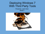
A PVC in direct access mode or a Bay Networks Standard interface
calculates the IP address by adding 1 to the IP address of the
interface that received the request.
For example, in Figure 1-1, the upstream router’s interface address is
192.32.1.1. This means that the upstream router calculates 192.32.1.2 as
the booting router’s IP interface.
1-6
303549-A Rev 00
Selecting a Boot Configuration
ASN router
BOOTP response
with IP address
192.32.1.2
IP address 192.32.1.1
Key
BOOTP request
BOOTP response
Upstream router
CAS0001A
Figure 1-1.
Getting an IP Address from a Bay Networks Standard Circuit
or a Frame Relay PVC in Direct Access Mode
Note: If the IP address plus 1 equals a broadcast address, the upstream router
calculates the IP address by subtracting 1. For example, if its interface is
7.255.255.254, the IP interface for the booting router is 7.255.255.253.
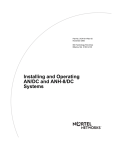
b.
A PVC in group access mode references its BOOTP client interface
table to find an associated IP address for the booting router.
Note: The BOOTP client interface table contains a data link connection
identifier (DLCI) and IP address pair for each PVC. You use Site Manager to
create this table when you follow the instructions in Chapter 3.
303549-A Rev 00
1-7
Connecting ASN Routers to a Network
For example, in Figure 1-2, routers 1, 2, and 3 send BOOTP requests for
IP addresses.
Booting router 1
Booting router 2
Booting router 3
Frame Relay
Circuit containing three (3) PVCs
(DLCIs 31, 32, and 33 for virtual
connections to routers 1, 2, and 3)
Key
BOOTP request
BOOTP response
Upstream router
CAS0002A
Figure 1-2.
Getting an Address from a PVC in Group Access Mode
The upstream router receives the requests on PVCs 31, 32, and 33,
respectively.
The upstream router refers to DLCI 31 in the BOOTP Client Interface
Table (Table 1-2), finds the IP address (192.32.16.17) associated with the
DLCI, and sends a BOOTP response containing the IP address back to
PVC 31.
The upstream router does the same for the other two circuits.
1-8
303549-A Rev 00
Selecting a Boot Configuration
Table 1-2.
Sample BOOTP Client Interface Table on Upstream Router
DLCI of Incoming BOOTP
Request for IP Address
Response
31
192.32.16.17
32
192.32.16.18
33
192.32.16.19
6.
The upstream router sends the IP address and subnet mask to the
booting router in a BOOTP response message.
7.
The ASN assigns the IP address and subnet mask to any synchronous
interface that receives a BOOTP response.
8.
The ASN stores these addresses, along with the address of the next-hop
router, in RAM.
Getting the Software Image and Configuration Files
After it gets the IP address, the ASN obtains its software image and configuration
files as follows:
1.
The ASN sends a BOOTP request for the pathnames of a configuration
file and software image file.
The ASN issues this request simultaneously through all synchronous and
Ethernet interfaces that have IP addresses. It issues this request periodically
through these ports for about 3 minutes, regardless of whether a cable is
connected.
303549-A Rev 00
1-9
Connecting ASN Routers to a Network
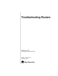
2.
A BOOTP server responds to the router’s request with the directory
pathnames; the ASN stops sending BOOTP requests for the pathnames
(Figure 1-3).
The first ASN interface that processes the BOOTP response acts as the TFTP
client in the remaining steps.
ASN router
BOOTP
server
Pathnames
Corporate backbone
Key
BOOTP request
BOOTP response
CAS0003A
Figure 1-3.
1-10
Getting the Pathnames of the Software Image and Configuration Files
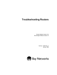
3.
The ASN sends a TFTP request for the configuration file.
4.
The BOOTP server uses TFTP to transfer the configuration file
(Figure 1-4).
5.
The ASN sends a TFTP request for the image file.
6.
The BOOTP server uses TFTP to transfer the image file (Figure 1-4).
303549-A Rev 00
Selecting a Boot Configuration
ASN router
1. Configuration file
2. Kernel
3. Application files
Corporate backbone
BOOTP server
Key
TFTP request
TFTP response
CAS0004A
Figure 1-4.
Getting the Startup Files
7.
The router boots.
8.
The router uses TFTP to get application files as it needs them.
The ASN can continue to request files, even after it begins bridging and
routing traffic.
9.
The router begins bridging and routing network traffic in accordance
with the configuration file.
If a network boot fails, the ASN waits to be booted by a neighboring slot. (A
single-slot ASN will instead attempt the Local Boot procedure.)
Note: The ASN supports Netbooting over multiple slots. The first slot to
retrieve startup files forces the other slots to use those files.
303549-A Rev 00
1-11
Connecting ASN Routers to a Network
Selecting the Startup Method
Use the information in the following sections to choose the boot method for both
the initial startup of the ASN and for day-to-day operations. Refer to the last
section of this chapter, “Completing a Network Boot Option,” for a summary of
the steps for completing the method you choose.
Booting the Router for the First Time
You coordinate the ASN’s initial startup with a person at the router site, who
physically installs and cables the ASN and initiates the desired startup procedure.
The manual Installing and Maintaining ASN Routers and BNX Platforms
describes these tasks in detail.
Note: To boot using any method, the asn.exe image must be on the local ASN
file system.
After you select the initial startup configuration (and set up the network as
described in this guide), direct the person at the router site to begin the appropriate
startup option.
Note: As an alternative to another person performing the initial startup at the
remote site, you can perform these tasks using a modem connection.
EZ-Install
EZ-Install is the default option for a new ASN router. You can use EZ-Install for
the initial startup if
•
There is a communications link between the ASN and an upstream router over
an HDLC or Frame Relay interface.
•
A directory on a BOOTP server contains a customized configuration file for
the ASN.
EZ-Install is the easiest option for the person at the ASN site to perform, since the
network automatically supplies the IP address and configuration file. This option
does not require a router connection to a modem or console.
1-12
303549-A Rev 00
Selecting a Boot Configuration
Netboot
You can use Netboot if
•
The ASN has a communications link to an upstream router over an Ethernet,
HDLC, or Frame Relay interface.
•
The ASN has a local console or modem connection.
•
A directory on a BOOTP server contains an ASN software image file and a
customized configuration file.
•
You provide a network configuration file customized for the ASN.
•
You configure an IP address for the ASN’s boot interface.
Netboot takes longer than EZ-Install, but minimizes the cost of line usage and
prevents saturation of the router’s memory.
Local Boot
When you use Local Boot as the initial boot option, the router boots a default
(generic) configuration file. You must then complete the “Quick-Start” installation
script to customize the default configuration file and save it locally. Refer to the
manual Quick-Starting Routers.
Recommendations
Even if you choose EZ-Install, we strongly recommend that you connect a modem
or a console to the router. With a console connection, you can issue commands to
the router and display messages. This is very useful if you have network problems
after installing the router.
303549-A Rev 00
1-13
Connecting ASN Routers to a Network
Booting the Router Routinely
This section compares the Netboot, Directed Netboot, and Local Boot options to
help you choose a boot configuration for routine startups.
Note: You can use Netboot for some procedures and Local Boot for others,
provided you set up the network to support Netboot.
Netboot
Using Netboot for routine startups allows you to
•
Manage software image and configuration files from a remote location by
storing them on the BOOTP server.
This option greatly simplifies the management of a number of routers by
allowing you to concentrate on keeping the startup files up to date in a single,
central location -- the BOOTP server.
•
Minimize the need to maintain the router’s local file system.
When the router gets files from a BOOTP server, it stores the files in memory,
not in its file system, reducing the need for frequent file system compactions.
(Refer to Using Technician Interface Software or Configuring and Managing
Routers with Site Manager to learn about file system compaction.)
•
Get application files from the BOOTP server as the ASN needs them.
Getting these files individually, rather than getting the entire asn.exe file,
minimizes the cost of line usage and prevents saturation of the router’s
memory.
One disadvantage of Netboot is that it requires the most time to boot the router.
Directed Netboot
Directed Netboot reduces network traffic and is generally faster than normal
Netboot. On routine startups, the router bypasses the original Netboot BOOTP
negotiation with the BOOTP server for the IP address, software image file, and
configuration file, entering the file transfer phase directly, at which time the TFTP
server transfers the startup files to the router.
1-14
303549-A Rev 00
Selecting a Boot Configuration
You use the ifconfig and bconfig commands with the Technician Interface or
Site Manager to define
•
The IP address of the TFTP server, using bconfig
•
The router’s IP address, using ifconfig
•
The complete pathnames of the startup files that the router will obtain from
the TFTP server, using bconfig
Directed Netboot is usually reserved for starting the router after the initial startup
because you need to know the exact location of the software image and
configuration files.
Local Boot
Local booting for routine startups allows you to
•
Minimize the time it takes to boot.
Local boot takes 2 to 3 minutes. Typically, Netbooting an image takes a little
longer. Over a low-speed WAN or after configuring the router to run
numerous protocols, Netbooting an image can take up to 15 or 20 minutes.
It also takes less time to local boot a configuration file than it does to Netboot
one. In most configurations, however, the difference between the two options
is only a few seconds.
•
Minimize line usage.
Getting files from a BOOTP server adds traffic to your network during the
booting process.
Recommendations
Bay Networks recommends that you
303549-A Rev 00
•
Set up the network to support Netboot, even if you plan to use the Local Boot
option for the initial configuration and for subsequent restarts.
•
Maintain the software image (asn.exe) on the local file system at all times, in
case you want to use Local Boot to start the ASN.
•
Maintain a local configuration file for the ASN, although it is not required to
Netboot the ASN successfully. The presence of a local config file provides
network connectivity if TFTP transfer fails during Netboot.
1-15
Connecting ASN Routers to a Network
Completing a Network Boot Option
This section lists the steps required for
•
EZ-Install
•
Netboot
•
Directed Netboot
To proceed with the Local Boot option, go directly to the manual Quick-Starting
Routers.
Note: To boot an ASN over the network, the ASN must be running Router
Software Version 8.10 or later (or BayStream Software Version 5.00 or later),
and all routers in the path between the ASN and the BOOTP server must be
running Version 7.60 (BayStream 5.00) or later.
EZ-Install
Note: To use EZ-Install over a Frame Relay circuit, make sure the upstream
router is running Router Software Version 7.80 or later (or BayStream
Software Version 5.00 or later).
The EZ-Install option requires the following steps:
1.
You use the Configuration Manager in local mode to create a complete
configuration file for the router.
(See Chapter 3 and the manual Configuring and Managing Routers with Site
Manager.)
2.
You set up the network to support BOOTP.
(See Chapter 2.)
3.
You create a BOOTP relay interface table on the upstream router to
support automated addressing, and configure all routers between the
BOOTP server and the booting router as BOOTP relay agents.
(See Chapter 2.)
1-16
303549-A Rev 00
Selecting a Boot Configuration
4.
The person at the ASN site installs and boots the router.
(See the manual Installing and Maintaining ASN Routers and BNX
Platforms.)
5.
The ASN gets a software image from the local file system, an IP address
from the upstream router, and the customized configuration file from the
BOOTP server.
(Described in the previous section; no action required.)
If the configuration file meets your network requirements, the ASN starts bridging
and routing traffic.
You can use the Site Manager Statistics Manager and Events Manager tools to
verify that the router is routing traffic according to the configuration you want.
(See the manual Configuring and Managing Routers with Site Manager.)
Netboot
Note: On a Frame Relay circuit, make sure the upstream router software is
Version 7.71 or later (or BayStream Software Version 6.00 or later).
The Netboot option requires the following steps:
1.
You use the Configuration Manager in local mode to create a complete
configuration file for the router.
(See Chapter 3 and the manual Configuring and Managing Routers with Site
Manager.)
2.
You set up the network to support BOOTP.
(See Chapter 2.)
3.
You use Site Manager to enable BOOTP on each router interface in the
path between the router and the BOOTP server.
(See Chapter 2.)
303549-A Rev 00
1-17
Connecting ASN Routers to a Network
4.
The person at the ASN site establishes a Technician Interface session (or
you establish a session via modem).
(See the manual Installing and Maintaining ASN Routers and BNX
Platforms.)
5.
The person at the ASN console uses the bconfig and ifconfig commands
to configure a synchronous or Ethernet interface.
(See Chapter 4 and the manual Installing and Maintaining ASN Routers and
BNX Platforms.)
6.
You install the netboot.exe file in the BOOTP server’s file system, and
make sure the image and application files reside in the same directory.
(See Chapter 2.)
7.
The person at the router site boots the router.
(See the manual Installing and Maintaining ASN Routers and BNX
Platforms.)
After the router boots, it gets a configuration file from a BOOTP server and
loads the software image from the local file system.
If the configuration file meets your network requirements, the router starts
bridging and routing traffic.
You can use the Site Manager Statistics Manager and Events Manager tools to
verify that the router is routing traffic according to the configuration you want.
(See the manual Configuring and Managing Routers with Site Manager.)
1-18
303549-A Rev 00
Selecting a Boot Configuration
Directed Netboot
Note: To use Directed Netboot, make sure the upstream router is running
Router Software Version 8.10 or later (or BayStream Software Version 5.00 or
later).
The Directed Netboot option requires the following steps:
1.
You use the Configuration Manager in local mode to create a complete
configuration file for the router.
(See Chapter 3 and the manual Configuring and Managing Routers with Site
Manager.)
2.
You set up the network to support TFTP.
(See Chapter 2.)
3.
The person at the ASN site establishes a Technician Interface session (or
you establish a session via modem).
(See the manual Installing and Maintaining ASN Routers and BNX
Platforms.)
4.
The person at the ASN console issues bconfig and ifconfig commands to
configure a synchronous or Ethernet interface for Directed Netboot.
(See Chapter 4 if you are using a remote Technician Interface session, or the
manual Installing and Maintaining ASN Routers and BNX Platforms if at the
ASN site.)
5.
The person at the router site boots the router.
(See the manual Installing and Maintaining ASN Routers and BNX
Platforms.)
The router boots from a local software image and downloads the
configuration file from a TFTP server.
The router starts bridging and routing traffic.
You can use the Site Manager Statistics Manager and Events Manager tools to
verify that the router is routing traffic according to the configuration you want.
(See the manual Configuring and Managing Routers with Site Manager.)
303549-A Rev 00
1-19
Chapter 2
Setting Up a UNIX Boot Server
To support network booting, you need to set up a UNIX workstation on the
network. This chapter describes what you need to do at the UNIX workstation to
prepare for booting an ASN over the network.
When a router boots over the network, it gets necessary startup files from a UNIX
server. When the ASN uses EZ-Install or Netboot, the server supplies
configuration file and/or software image file pathnames using Boot Protocol
(BOOTP). The ASN then retrieves the files using Trivial File Transfer Protocol
(TFTP). When the ASN uses Directed Netboot, it already knows the pathnames of
the files it needs and retrieves the files directly from the server using TFTP.
To configure EZ-Install or Netboot, complete the steps in both “Setting Up a
BOOTP Server” and “Setting Up a TFTP Server.” To configure Directed Netboot,
complete the steps in “Setting Up a TFTP Server.”
Setting Up a BOOTP Server
To support EZ-Install or Netboot, an ASN needs a network connection to a
BOOTP server. You configure a UNIX workstation as a BOOTP server by
•
Setting up BOOTP sockets
•
Configuring BOOTPD (the BOOTP daemon)
Note: A daemon is an unattended process (that is, one that runs in the
background). An application typically calls up a daemon to perform a standard
routine or service (in this case, BOOTP).
On Sun workstations, you must first copy the BOOTPD program to the
appropriate directory.
303549-A Rev 00
2-1
Connecting ASN Routers to a Network
Copying the BOOTPD Program on Sun Workstations
Depending on the operating system you use, Bay Networks may or may not ship
BOOTPD with the Site Manager package. The AIX and HP-UX operating
systems already have BOOTPD. SunOS and Solaris do not, however, so Site
Manager automatically installs BOOTPD on Sun workstations running SunOS
and Solaris.
Copy the bootpd file to the /etc directory as follows:
1.
Log in to the UNIX workstation as root.
2.
Enter the following command:
cp /usr/wf/bin/bootpd /etc
Setting Up BOOTP Sockets
A socket is a UNIX mechanism for creating virtual connections between operating
system and network processes. For each socket, the /etc/services file must include
a user datagram protocol (UDP) descriptor that provides process-to-process
addressing information.
Set up the send and receive sockets for the BOOTP process as follows:
1.
Log in to the UNIX workstation as root.
2.
Use a text editor to insert the following two lines into the /etc/services file:
bootps
67/udp
# bootp server
bootpc
68/udp
# bootp client
Setting Up BOOTPD to Run
Configure your workstation to run the BOOTPD program when it receives a
BOOTP request packet, as follows:
2-2
1.
As root, use a text editor to open the /etc/inetd.conf file.
2.
Make sure that no other line in the file begins with “bootps.”
303549-A Rev 00
Setting Up a UNIX Boot Server
If there is such a line, your workstation is already configured as a BOOTP
server. Comment out this line by entering a pound sign (#) at the beginning of
the line, so that the server will use the BOOTPD program that you specify in
the next step.
3.
Insert the following line anywhere in the file to configure your
workstation as a BOOTP server:
bootps dgram udp wait root /etc/bootpd bootpd
4.
Save and exit the file.
Setting Up BOOTPD to Respond to Routers
When the operating system receives a BOOTP packet, it starts up BOOTPD. The
BOOTPD software matches the source IP address of the packet to an IP address in
its BOOTP table (bootptab) file to determine the pathnames to configuration and
boot image files.
Note: The bootptab file can include the same boot image pathname for all
booting routers, or a different boot image for each IP addresses.
Entries in bootptab also include optional parameter tags. Bay Networks supplies a
sample bootptab file that Site Manager installs automatically in the
/usr/wf/config directory. Use a copy of this sample file if you do not already have a
bootptab file.
Set up BOOTPD to respond to booting routers, as follows:
1.
As root, view the contents of the /etc directory to determine whether it
already contains a bootptab file.
If it does contain a bootptab file, disregard Steps 2 and 3 and continue with
Step 4 to edit this file.
2.
Issue the following command to copy the bootptab file to the /etc
directory:
cp /usr/wf/config/bootptab /etc
3.
303549-A Rev 00
Use an editor to open the bootptab file in the /etc directory.
2-3
Connecting ASN Routers to a Network
4.
Type the information that pertains to the ASNs in your network into the
bootptab file.
The section that follows explains how to format your entries. Use Tables 2-1
and 2-2 to determine which tags and values you need. Figure 2-1 shows the
sample bootptab file included with the Site Manager software. The comments
in this file explain the sample definitions.
5.
After editing the bootptab file, be sure to save the changes.
Note: Be sure the bootptab file resides in the /etc directory. BOOTPD fails if it
cannot find the bootptab file in /etc.
Editing the bootptab File
Enter a <hostname> definition in the bootptab file for each ASN in your network.
The format of each definition in the bootptab file is as follows:
<hostname>:\
:<tg>=<value>:\
:<tg>=<value>:\
:<tg>=<value>:
•
<hostname> is a name you assign to a BOOTP client. (Each router is a client.)
•
<tg> is a BOOTP parameter name (tag).
•
Follow each tag with an equal sign (=) and a value.
•
A pound sign (#) at the beginning of a line indicates a comment.
•
A backslash (\) at the end of a line indicates continuation of the line.
Note: Make sure you enter a backslash (\), not a slash (/), at the end of every
line that does not conclude a definition.
2-4
303549-A Rev 00
Setting Up a UNIX Boot Server
Keep the following in mind when editing bootptab:
•
The <hostname> definition can contain a maximum of 79 characters.
•
The first character must be alphabetic.
•
All characters must be alphanumeric.
•
You can use a dot (.) to separate characters, but the character immediately
following the dot must be alphabetic.
•
The hostname definition cannot contain an underscore.
Table 2-1 lists the tags for router host names. Table 2-2 lists the tags for boot
image names.
Table 2-1.
303549-A Rev 00
BOOTPD Tags for a Router Host Name
Tag
Required or
Optional
ip
Value
Example
Required
IP address -- the host IP address
of the router.
ip=192.32.5.2
sm
Optional
Subnet mask -- the host subnet
mask of the router.
sm=255.255.255.0
T129
Required
Pathname of the router
configuration file. The maximum
path length is 49 characters.
T129="/usr/cfg/
asn_Bost.cfg"
T130
Required
Size of the router configuration file T130=0x0004
in 512-byte blocks. The setting of
this tag determines how much
memory the router allocates for
the file. Set this tag to 0x0004.
tc
Optional
tc=general
Table continuation -- pointer to a
definition in another location in the
same file for additional
information. The information this
tag points to is common to all
routers that need to boot using
BOOTP. If information in a
definition for a specific router is
inconsistent with the definition this
tag points to, BOOTPD uses the
information for the specific router.
2-5
Connecting ASN Routers to a Network
Table 2-2.
BOOTPD Tags for a Boot Image Name
Tag
Required
or Optional
hd
Required
Home directory -- the directory on hd=/$HOME/.builder_dir/
the workstation containing the boot rel900/asn
files. By default, the Image Builder
writes its files to the directory
specified in the example. The
rel... number is the version
number of the current router
software release. If you change
the default or move the files to
another directory, specify that
directory.
bf
Required
Boot file -- the name of the boot
image.
bs
Required
Boot size -- the size of the boot file bs=auto
in 512-octet blocks. If you specify
auto as the size, the BOOTP
server calculates the size of the
file for each BOOTP request.
vm
Required
vm=rfc1048
Vendor magic cookie selector -the BOOTP server should always
reply in a manner compliant with
RFC 1048. You must enter
rfc1048 for this tag, so that the
router can understand the BOOTP
responses it receives.
Value
Example
bf=krnl_asn.exe
The sample bootptab file in Figure 2-1 enables two ASNs (named “ASN.Boston”
and “ASN.Chicago”) to boot across the network. Use the basic format shown in
Figure 2-1 to set up your own bootptab file.
2-6
303549-A Rev 00
Setting Up a UNIX Boot Server
# This file contains the default specification for the boot
# image file to be used by all ASNs.
# "general" contains information that is common to all ASNs
# that need to boot via BOOTP. You can use any word in place
# of "general."
general:\
#
#
#
#
#
#
#
"hd" specifies that /$HOME/.builder_dir/re900/asn is the
directory on the workstation where the boot files are
located. By default, the Image Builder writes its files to
this directory. If you are using a router software version
later than 7.80, add the associated three digits to the end
of the "rel" directory name. If you moved the files to
another directory, specify that directory.
:hd=/$HOME/.builder_dir/rel900/asn:\
# "bf" specifies that the name of the boot image kernel file
# is krnl_asn.exe.
:bf=krnl_asn.exe:\
# "bs" indicates the size of the boot file. If you specify
# "auto" as the size, the BOOTP server calculates the size of
# the file for each BOOTP request.
:bs=auto:\
#
#
#
#
"vm" indicates that the BOOTP server should always reply in
a manner compliant with RFC 1048. You must enter rfc1048
for this tag so that the ASN can understand the BOOTP
responses it receives.
:vm=rfc1048:
# This line marks the beginning of the active definition for
# the ASN we are naming "ASN.Boston."
ASN.Boston:\
# "ip" indicates the IP address of the ASN.
:ip=192.32.5.2:\
# "T130" indicates the size of the ASN’s configuration file in
# 512-byte blocks. Always use 0x0004.
:T130=0x0004:\
# "T129" indicates the pathname of the configuration file
# for the ASN.
:T129="/usr/cfg/ASN_Bost.cfg":\
# "tc" indicates that the "general" definition contains more
# information that applies to BOOTP transmissions to
303549-A Rev 00
2-7
Connecting ASN Routers to a Network
# "ASN.Boston."
:tc=general:
# This is the active definition for the ASN we are naming
# "ASN.Chicago."
ASN.Chicago:\
:ip=10.0.0.4:\
:T130=0x0004:\
:T129="/usr/cfg/ASN_Chic.cfg":\
:tc=general:
Figure 2-1.
Sample bootptab File
Verifying Consistent BOOTP Service
You may want to configure a second workstation as a BOOTP server for backup
purposes. If you do so, make sure the two bootptab files match exactly. Also,
make sure that the image and string files are from the same software version.
Setting Up a TFTP Server
An ASN needs a network connection to a TFTP server to complete EZ-Install,
Netboot, or Directed Netboot. You configure a UNIX workstation as a TFTP
server by
•
Setting up TFTPD (the TFTP daemon)
•
Adding a TFTP user (for an HP 9000 only)
•
Setting up static routes to routers (optional)
•
Loading the changes into memory
Note: A daemon is an unattended process (that is, one that runs in the
background). An application typically calls up a daemon to perform a standard
routine or service (in this case, TFTP).
When you set up the TFTPD server on a UNIX workstation, you can allow TFTP
to access the root directory and any subdirectory or restrict its access to a specified
directory or pathname.
2-8
303549-A Rev 00
Setting Up a UNIX Boot Server
Allowing the router to access the root directory and any subdirectory is the
simpler procedure. Specifying a pathname provides security, but it requires
linking TFTPD.
Providing TFTPD Access to the Root Directory
To provide TFTPD access to files in the root directory and to all subdirectories,
verify or insert the appropriate line for your operating system in the /etc/inetd.conf
file.
Refer to the sample line for your operating system in Table 2-3.
Table 2-3.
Providing TFTPD Access to Root and All Subdirectories
Operating System
Sample Line to Insert in /etc/inetd.conf File
SunOS
tftp dgram udp wait root /usr/etc/in.tftpd in.tftpd -s /
Solaris
tftp dgram udp wait root /usr/sbin/in.tftpd in.tftpd -s /
HP-UX
tftp dgram udp wait root /etc/tftp tftp
AIX
Use the System Management Interface Tool (SMIT) to configure TFTP. For
instructions, refer to the IBM guides on TCP/IP daemons and the TFTP protocol.
Restricting TFTPD Access to a Specified Directory
To restrict TFTPD file access to a specific directory, insert the appropriate line for
your operating system in the /etc/inetd.conf file.
The examples in Table 2-4 restrict access to the /tftpboot directory. You can
substitute any directory you want.
Table 2-4.
Restricting TFTPD Access to One Directory
Operating System
Sample Line to Insert in /etc/inetd.conf File
SunOS
tftp dgram udp wait root /usr/etc/in.tftpd in.tftpd -s /tftpboot
Solaris
tftp dgram udp wait root /usr/sbin/in.tftpd in.tftpd -s /tftpboot
HP-UX
tftp dgram udp wait root /etc/tftp tftp -s /tftpboot
AIX
Use the System Management Interface Tool (SMIT) to configure TFTP. For
instructions, refer to the IBM guides on TCP/IP daemons and the TFTP protocol.
303549-A Rev 00
2-9
Connecting ASN Routers to a Network
Creating Links
You must create a symbolic link for every pathname you specify in the bootptab
file. For example, to set up the symbolic links for the /tftpboot path, use the
following procedure:
1.
Log in to your UNIX workstation as root.
2.
Enter the following commands:
cd tftpboot
ln -s . usr
ln -s . tftpboot
Caution: Do not insert a slash (/) in the cd tftpboot command; a symbolic
link cannot contain references to directories above the directory specified in
the tftpd command line. Use the -s flag to provide additional security to your
network. (This flag restricts TFTPD access to a specified directory.)
Adding a TFTP User for an HP 9000
Follow the instructions in this section only if you are using an HP 9000 as the Site
Manager workstation.
To add a TFTP user for the HP 9000, enter a line with the following syntax in your
/etc/passwd file. We recommend that you use root (/) as the TFTP home directory.
tftp::<user_id>:<group_no.>::/:/bin/false
For example:
tftp::510:20::/:/bin/false
Note: We recommend that you not use the System Administration Manager
(SAM) utility as an alternative to editing the /etc/passwd file.
2-10
303549-A Rev 00
Setting Up a UNIX Boot Server
Setting Up Static Routes to Next-Hop Routers
If your workstation requires static routes, use this section to specify a path to the
network by
•
Editing the inetd.conf file
•
Verifying the routes
•
Loading the changes into memory
You must set up a static route for each path between the routers and the BOOTP
server’s next-hop router.
You may want to specify a static route in a multihop environment or in an
environment using routing protocols such as RIP, where minor routing update
delays may extend the time it takes to Netboot.
Editing the inetd.conf File
Add the following line to the inetd.conf file to set up a static route:
route add <destination> <gateway> <hops>
<destination> is the IP address of the ASN or its network.
<gateway> is the IP address of the network destination to which packets are to be
addressed.
<hops> is the number of hops to the network destination.
Verifying the Routes
After adding a static route for each path to the booting routers, enter the following
command to display the routing table and verify the route you added:
netstat -r
303549-A Rev 00
2-11
Connecting ASN Routers to a Network
Loading the Changes into Memory
Once you modify the inetd.conf file, you must force the operating system to reread
it by rebooting the workstation or by issuing a hang-up signal.
In most cases, reboot the workstation. Issue a hang-up signal if the workstation is
performing a task that you do not want to interrupt.
Rebooting
Reboot your workstation as follows:
1.
Log in as root.
2.
Execute the following command:
/etc/shutdown now -r
The -r flag reboots the workstation.
Issuing a Hang-Up Signal
Issue a hang-up signal as follows:
1.
Log in as root.
2.
Execute the following command to hang up on the inetd process:
ps -aux | grep inetd
The system displays a line similar to this one:
root
3.
148
0.0
0.0
48
0 ?
IW
Jan 14
0:07 inetd
Execute the following command, using the first number in the line after
the word “root” (in this case, 148):
kill -1 148
The inetd process rereads the inetd.conf file.
What to Do Next
Before you can use the network to boot an ASN, you must also complete the steps
in Chapter 3.
2-12
303549-A Rev 00
Chapter 3
Configuring Network Booting
This chapter describes how to use Site Manager to configure network booting for
routers in the network.
Note: Before the router can get files over the network, you must also set up a
UNIX server on the network, as described in Chapter 2.
Sections of this chapter explain how to complete the tasks required for configuring
EZ-Install, Netboot, or Directed Netboot.
To Configure This Boot Method
Complete This Section
EZ-Install, Netboot, or Directed Netboot
“Preparing Configuration and Image Files”
Netboot or Directed Netboot
“Enabling Netboot or Directed Netboot”
Netboot or Directed Netboot
“Configuring a Netboot Interface”
Netboot
“Setting Up Routing Paths”
EZ-Install over Frame Relay
group-access PVC
“Creating a BOOTP Client Interface Table“
Note: The steps in this chapter assume a local, dynamic, or remote
Site Manager connection with the ASN. Refer to Chapter 4 and to Installing
and Maintaining ASN Routers and BNX Platforms for information about
making the ASN initial Site Manager connection.
303549-A Rev 00
3-1
Connecting ASN Routers to a Network
Preparing Configuration and Image Files
Unless the ASN will use the default (generic) configuration file and software
image that ship on its local file system, you must create
•
A unique configuration file for each remote router
•
A uniform software image that all routers in your network can use
Creating Configuration Files
Prepare network configuration files as follows:
1.
Use the Configuration Manager in local mode to create a configuration
file for each ASN.
Refer to Configuring and Managing Routers with Site Manager for
instructions.
2.
Record the name of each configuration file and corresponding ASN for
later reference.
When you name configuration files, keep the following in mind:
3.
3-2
•
Configuration files that you save on a BOOTP server do not have to be
named config.
•
Configuration filenames must begin with an alphabetical character. The
remaining characters must be alphanumeric and may also include the
underscore (_) character. You cannot use spaces.
•
Configuration filenames can consist of 1 to 15 characters, including a dot
(.). We recommend that you limit filenames to eight characters to ensure
that all operating systems Bay Networks supports can recognize the
names.
•
Configuration filename extensions are optional and must follow a
filename and a dot. We recommend that you limit filename extensions to
three characters.
•
BOOTP allows a maximum number of 49 characters in a path, including
slashes, filename, optional dot, and filename extension.
If the BOOTP server and Site Manager do not reside on the same
workstation, transfer the configuration files to the BOOTP server.
303549-A Rev 00
Configuring Network Booting
Preparing an Image
If you want the ASN to automatically boot a network image when starting up
(using EZ-Install, Netboot, or Directed Netboot), you must use the Site Manager
Image Builder to change the default setting before you attempt to start up.
Note: BayStream software does not support Image Builder.
To use Image Builder:
1.
On the Site Manager workstation, open the software image file in the
Image Builder.
Keep the following in mind:
•
•
•
•
Be sure to select the correct image. If you select an image for another router
type, you cannot generate the correct files.
If you configure the router to obtain its image from the network, it cannot
Netboot the image until the kernel image is available on the BOOTP server.
Make sure that you extract the software image and all the application (.exe)
files in the ASN directory. The files must be from the same software image
file whose components were created from the same version of software. If
these files are from different software versions, the router may fail to boot or
operate properly.
Refer to Configuring and Managing Routers with Site Manager for more
instructions.
After you open the image file, the Image Builder automatically generates the
kernel image and application files.
By default, the Image Builder stores these files in /$HOME/.builder_dir/
rel<rel>/asn (where <rel> is the current router software release for the router).
For example, Version 3.00 of the Site Manager Image Builder tool stores
Version 9.00 files for an ASN in the /$HOME/.builder_dir/rel900/asn
directory.
For additional instructions on how to use the Image Builder, refer to
Configuring and Managing Routers with Site Manager.
2.
303549-A Rev 00
If you use a different workstation as a BOOTP server, transfer all of the
files in the directory that contains the kernel file to the new workstation.
3-3
Connecting ASN Routers to a Network
Enabling Netboot or Directed Netboot
By default, the router obtains its software image from its local file system and its
configuration file from a BOOTP server. You can display and change these
settings as follows:
1.
Figure 3-1.
Select Protocols > Global Protocols > Net Boot > Global from the
Configuration Manager window (Figure 3-1).
Displaying the Netboot Interfaces Window
The Edit Netboot Global Parameters window appears (Figure 3-2).
3-4
303549-A Rev 00
Configuring Network Booting
Figure 3-2.
Edit Netboot Global Parameters Window
2.
To enable Netboot, specify Enable for at least one of the first two
parameters.
3.
To enable Directed Netboot, specify Enable for at least one of the first two
parameters and configure each of the last three parameters.
For guidelines, see the following parameter descriptions.
4.
303549-A Rev 00
Click on OK to apply parameter edits.
3-5
Connecting ASN Routers to a Network
Netboot and Directed Netboot Parameters
Note: Of the five parameter fields shown in Figure 3-2, the first two (Boot
Image From Network and Boot Config From Network) apply to both Netboot
and Directed Netboot. The last three parameters are for Directed Netboot only.
Parameter:
Boot Image From Network
Default:
Disable
Options:
Enable | Disable
Function:
Instructions:
Enables or disables retrieval of the software image from the BOOTP
server the next time the router starts up.
Set to Disable if you want to boot using the image in the router’s local file
system. This setting reduces the time it takes to boot the router and
eliminates using network bandwidth to obtain the image.
Set to Enable if
MIB Object ID:
•
You want the router to obtain the image from a BOOTP server and
you have already set up the network to support BOOTP service.
•
You are upgrading the image on a number of routers. The routers can
then boot using a single image on the BOOTP server. You must
ensure that the directory name in the bootptab file matches the
location of the upgraded image before you boot the routers.
1.3.6.1.4.1.18.3.3.2.10.1.1
Note: As an alternative to enabling the Boot Image From Network parameter,
you can use the Router Files Manager to transfer an upgraded image to the
ASN. To do this, delete the ASN’s software image file, compact the file
system, and copy the upgraded image file to the ASN. Use the Router Files
Manager to confirm that the upgraded image on the router is the same size as
that on the Site Manager workstation. This verifies that the file transfer was
successful.
3-6
303549-A Rev 00
Configuring Network Booting
Parameter:
Boot Config From Network
Default:
Enable
Options:
Enable | Disable
Function:
Instructions:
Enables or disables retrieval of the configuration file from a BOOTP
server the next time the router starts up.
Set to Disable if you have already saved the configuration file in memory
to the router’s local file system, and you want to boot using this
configuration file. This setting reduces the time it takes to boot the router
and eliminates using network resources to obtain the configuration file.
Set to Enable if you want the router to obtain the configuration file from a
BOOTP server and you have already set up the network to support
BOOTP service.
MIB Object ID:
Parameter:
1.3.6.1.4.1.18.3.3.2.10.1.2
Boot Server Address
Default:
None
Options:
A valid IP address of a TFTP server
Function:
Instructions:
MIB Object ID:
303549-A Rev 00
When one or both of the parameters Boot Image From Network and Boot
Config From Network are set to Enable, this parameter specifies the
TFTP server from which the router will obtain the boot image and boot
configuration files.
Use this parameter only when configuring Directed Netboot. Enter the
valid IP address of the TFTP server, in dotted decimal notation.
1.3.6.1.4.1.18.3.3.2.10.1.3
3-7
Connecting ASN Routers to a Network
Parameter:
Boot Image Pathname
Default:
None
Options:
A valid image file pathname
Function:
When the parameter Boot Image From Network is set to Enable, this
parameter specifies the absolute pathname of the boot image file on the
TFTP server.
When you Netboot the router, this parameter shows the full path to the
active image on the remote server. When you boot an ASN locally, the
name of the active image (wfHwEntry.wfHwActiveImageName) appears in
the form <volume>:<image name>.
Instructions:
MIB Object ID:
Parameter:
1.3.6.1.4.1.18.3.3.2.10.1.4
Boot Config Pathname
Default:
None
Options:
A valid configuration file pathname
Function:
When the parameter Boot Config From Network is set to Enable, this
parameter specifies the absolute pathname of the boot configuration file
on the TFTP server.
Instructions:
Use this parameter only when configuring Directed Netboot. Make sure
the file you specify is the valid configuration file on the TFTP server.
MIB Object ID:
3-8
Use this parameter only when configuring Directed Netboot. Make sure
the file you specify is the valid image file on the TFTP server.
1.3.6.1.4.1.18.3.3.2.10.1.5
303549-A Rev 00
Configuring Network Booting
Configuring a Netboot Interface
When you enable Netboot or Directed Netboot, you must configure one or more
of the ASN’s circuits as a Netboot interface. If you are using EZ-Install, you do
not need to configure Netboot interfaces.
Follow these instructions to add a Netboot interface.
1.
Select Protocols > Global Protocols > Net Boot > Interfaces from the
Configuration Manager window.
The Netboot Interfaces window appears (Figure 3-3).
Figure 3-3.
Netboot Interfaces Window
The scroll box is empty unless this router has existing Netboot interfaces
configured.
2.
Click on Add.
The Netboot Interface window appears (Figure 3-4).
303549-A Rev 00
3-9
Connecting ASN Routers to a Network
Figure 3-4.
3.
Netboot Interface Window
Enter the appropriate slot number, module number, and port number
(connector identification).
For guidelines, see the Netboot Interface parameter descriptions that follow
these instructions.
Note: If you configure more than one circuit for Netboot, the first to receive a
reply from the BOOTP server will use Netboot to reach the router.
4.
Click on OK in the Netboot Interface window (Figure 3-4).
The slot number, module number, and connector identification of the
configured interface now appear in the scroll box of the Netboot Interfaces
window (Figure 3-3).
3-10
303549-A Rev 00
Configuring Network Booting
Netboot Interface Parameters
Parameter:
Slot Number
Default:
None
Range:
1 to 4
Function:
Instructions:
MIB Object ID:
Parameter:
Specifies the assigned slot number for the physical slot in which the net
module for this connector is installed.
Type the appropriate slot number in the Slot Number box.
None
Module Number
Default:
None
Range:
1 to 4
Function:
Instructions:
MIB Object ID:
Parameter:
Specifies which net module supports the connector.
Type the appropriate module number in the Module Number box.
None
Connector
Default:
None
Options:
COM1 | COM2 | XCVR1 | XCVR2
Function:
Instructions:
MIB Object ID:
303549-A Rev 00
Identifies the connector configured as a Netboot interface.
Enter the connector name for the Netboot interface. To use Netboot over a
synchronous interface, enter COM1 or COM2. To use Netboot over an
Ethernet interface, enter XCVR1 or XCVR2.
None
3-11
Connecting ASN Routers to a Network
Parameter:
Default:
None
Options:
Any valid IP address
Function:
Instructions:
MIB Object ID:
Parameter:
Specifies the IP address of the remote netbooting router that is using
EZ-Install. This parameter applies only to a Frame Relay group access
PVC connection.
Enter the IP address of the remote netbooting router’s interface, in dotted
decimal notation.
1.3.6.1.4.1.18.3.3.2.10.3.1.4
Connector Subnet Mask
Default:
None
Options:
The Configuration Manager automatically calculates an appropriate
subnet mask, depending on the class of the network to which the interface
connects. However, you can change the subnet mask with this parameter.
Function:
Specifies the network and subnetwork portion of the 32-bit IP address of
this interface.
Instructions:
MIB Object ID:
Parameter:
Either accept the assigned subnet mask or enter another subnet mask, in
dotted decimal notation.
1.3.6.1.4.1.18.3.3.2.10.3.1.5
Connector Next Hop
Default:
None
Options:
Any valid IP address
Function:
Specifies the IP address of the next-hop router connected to this interface.
When the router starts up, the next-hop router passes the BOOTP requests
and responses that initiate the transfer of the image or configuration file
between the router and the BOOTP server. If the router and BOOTP
server are on the same IP subnet, you do not have to set this parameter.
Instructions:
Enter the IP address of the next-hop router connected to the interface you
are adding, in dotted decimal notation.
MIB Object ID:
3-12
Connector IP Address
1.3.6.1.4.1.18.3.3.2.10.3.1.6
303549-A Rev 00
Configuring Network Booting
Parameter:
Connector Protocol Mask
Default:
Point to Point
Options:
Point to Point | Point to Point Internal Clock | Fr Relay Annexd | Fr Relay
Annexa | Fr Relay LMI
Function:
During the boot process the router will configure the synchronous
interface to the specified protocol.
Instructions:
MIB Object ID:
Specify the desired protocol option.
1.3.6.1.4.1.18.3.3.2.10.3.1.7
Parameter:
Connector State
Default:
Enable
Options:
Enable | Disable
Function:
Enables or disables the connector parameters. If you set this parameter to
Disable, the router cannot Netboot.
Instructions:
MIB Object ID:
If you do not want to use the settings on the Netboot Interfaces window,
select Disable. You must set this parameter to Enable to use any of the
other four parameters in the window.
1.3.6.1.4.1.18.3.3.2.10.3.1.1
Setting Up Routing Paths
You set up the routing path between a BOOTP server and a booting routers by
•
Enabling BOOTP relay interfaces on all routers between the server and the
booting router
•
Creating a BOOTP Relay Agent Forwarding Table for each router in the path
•
Creating a BOOTP Client Interface Table for the upstream router when the
booting router is on a Frame Relay PVC in group access mode
Note: If you are booting over an Ethernet LAN and the Site Manager
workstation is directly cabled to the LAN, you do not need to configure a
BOOTP routing path.
303549-A Rev 00
3-13
Connecting ASN Routers to a Network
Enabling Relay Interfaces
You must enable BOOTP relay (also called BOOTP pass-through or gateway) on
all interfaces in the paths between the booting routers and the BOOTP server.
Figure 3-1 shows an example of a network with BOOTP gateways.
Router A
Router B
Router C
Enable BOOTP on
these interfaces
BOOTP
server
Corporate backbone
CAS0006A
Table 3-1.
Enabling BOOTP in a Sample Network
Enable BOOTP relay on an interface as follows:
3-14
1.
Click on the connector in the Configuration Manager window.
2.
Select Edit Circuit in the Edit Connector window.
3.
Select Protocols > Add in the Circuit Definition window.
4.
Select BOOTP in the Select Protocols window and click on OK.
5.
Select File > Exit to exit the Circuit Definition window.
303549-A Rev 00
Configuring Network Booting
Creating BOOTP Relay Agent Forwarding Tables
You must create a BOOTP Relay Agent Forwarding Table for every router passing
BOOTP traffic between the router and the BOOTP server.
The BOOTP Relay Agent Forwarding Table allows you to specify the IP interface
that receives the incoming BOOTP request packets, and the associated IP interface
that forwards them. You can add multiple pairs of incoming and outgoing
interfaces to support connections to multiple routers in your network.
To create the BOOTP Relay Agent Forwarding Table, begin at the Configuration
Manager window and complete the following steps.
1.
Figure 3-5.
Select Protocols > IP > BOOTP > Relay Agent Interface Table in the
Configuration Manager window (Figure 3-5).
Displaying the BOOTP Relay Agent Interface Table
The BOOTP Relay Agent Interface Table window appears (Figure 3-6). This
window lists all IP interfaces on the router.
303549-A Rev 00
3-15
Connecting ASN Routers to a Network
Figure 3-6.
BOOTP Relay Agent Interface Table Window
Click on Help or refer to Configuring SNMP, RMON, BootP, DHCP, and
RARP Services for a description of the parameters in the BOOTP Relay Agent
Interface Table window.
Note: Be sure the Timeout Secs. parameter is set to the default: 0.
2.
Click on Forward I/F (interface).
The BOOTP Relay Agent Forwarding Table window appears (Figure 3-7).
3-16
303549-A Rev 00
Configuring Network Booting
Figure 3-7.
3.
BOOTP Relay Agent Forwarding Table Window
Click on Add.
The BOOTP Addresses window appears (Figure 3-8).
Figure 3-8.
4.
BOOTP Addresses Window
Specify the Input IP Address and Output IP Address parameters.
For help, refer to the parameter descriptions following these instructions.
5.
303549-A Rev 00
Click on OK.
3-17
Connecting ASN Routers to a Network
The BOOTP Relay Agent Forwarding Table window lists the connector and
input IP address on the left, and the connector and output IP address on the
right.
If you enter the IP address of an interface that is not configured, Site Manager
displays question marks (???) instead of the connector (for example,
??? 192.32.23.3). Once you configure the interface, Site Manager replaces the
question marks with the appropriate connector.
6.
Click on Done to exit the window.
BOOTP Relay Agent Interface Parameters
Parameter:
Default:
None
Options:
A valid IP address
Function:
Instructions:
MIB Object ID:
Parameter:
Specifies the IP interface that receives BOOTP request packets from an
external network. This interface must have BOOTP configured on it.
Enter the IP address of the interface through which the router will receive
BOOTP requests in dotted decimal notation.
1.3.6.1.4.1.18.3.5.3.8.3.2.1.3
Output IP Address
Default:
None
Options:
A valid IP address
Function:
Instructions:
MIB Object ID:
3-18
Input IP Address
Specifies the IP interface that forwards BOOTP request packets to an
external network.
Enter the IP address of the interface through which the router will forward
BOOTP requests in dotted decimal notation.
1.3.6.1.4.1.18.3.5.3.8.3.2.1.4
303549-A Rev 00
Configuring Network Booting
Creating a BOOTP Client Interface Table
The upstream router is a booting router’s next-hop router. By default, the booting
router’s synchronous interfaces automatically try to get IP addresses from the
upstream router. This is the EZ-Install process.
If an ASN using EZ-Install gets its address from the upstream router, and the
upstream router’s interface to the booting router is a Frame Relay group access
PVC, you must use Site Manager to connect to the upstream router and create a
BOOTP Client Interface Table (in addition to a BOOTP Relay Agent Forwarding
Table).
Note: You do not need to create a BOOTP Client Interface Table for Netboot
and Directed Netboot, if the EZ-Install Frame Relay PVC is configured to
operate in direct access mode, or if the EZ-Install circuit is configured to
operate with the Bay Networks Standard (HDLC encapsulation) protocol.
The BOOTP Client Interface Table allows you to specify and pair the IP address
of the booting router with the DLCI of the Frame Relay group access PVC. For
more information about the DLCI and Frame Relay, refer to Configuring Frame
Relay Services.
To create the BOOTP Client Interface Table, begin at the BOOTP Relay Agent
Interface Table window (Figure 3-6) and proceed as follows:
1.
Click on Client I/F.
The BOOTP Client Interface Table window appears (Figure 3-9).
303549-A Rev 00
3-19
Connecting ASN Routers to a Network
Figure 3-9.
2.
BOOTP Client Interface Table Window
Click on Add.
The BOOTP Client Interface Address window appears (Figure 3-10).
Figure 3-10.
3.
BOOTP Client Interface Address Window
Enter the booting router’s IP address and its associated DLCI number.
For help, refer to the parameter descriptions following these instructions.
4.
Click on OK.
The BOOTP Client Interface Table window now lists the client IP address and
DLCI number you added.
5.
3-20
Click on Done to exit the window.
303549-A Rev 00
Configuring Network Booting
BOOTP Client Interface Parameters
Parameter:
IP Address
Default:
None
Options:
Any valid IP address
Function:
Instructions:
MIB Object ID:
Parameter:
Default:
Range:
Function:
Instructions:
MIB Object ID:
Specifies the IP address of the booting router that is using EZ-Install. This
parameter applies only to a Frame Relay group access PVC connection.
Enter the IP address (in dotted decimal notation) of the booting router’s
interface.
1.3.6.1.4.1.18.3.5.3.8.1.1.1.3
DLCI Number
None
16 to 1007
Specifies the identification number of the upstream router’s PVC to the
booting router. The Frame Relay network uses the DLCI number to direct
data flow from the booting router to the upstream router.
Enter the number in decimal format. Use the DLCI number assigned by
your Frame Relay service provider.
1.3.6.1.4.1.18.3.5.3.8.1.1.1.2
What to Do Next
If you have not already done so, you must complete the steps in Chapter 2 to
configure a UNIX workstation for network booting before you can use the
network to boot an ASN.
303549-A Rev 00
3-21
Chapter 4
Setting Up an ASN as a Network Boot Client
Before an ASN can complete Netboot or Directed Netboot, you must configure at
least one of its synchronous or Ethernet interfaces to support network booting.
You can configure the Netboot interface from
•
The ASN Technician Interface console, as described in this chapter
•
A Site Manager workstation on the IP network, as described in Chapter 3
This chapter describes how to use a local console or remote modem Technician
Interface connection to set up the ASN as a network boot client by configuring
•
The source of the boot image and configuration file
•
The IP address of the Netboot interface
Note: You do not need to follow the instructions in this chapter to use the
EZ-Install boot option. Instead, refer to Installing and Maintaining ASN
Routers and BNX Platforms.
Working with a Person at the ASN Site
Written for a person at the ASN site, the manual Installing and Maintaining ASN
Routers and BNX Platforms provides instructions for setting up the ASN for each
of the boot options. The instructions in that manual assume that a network
administrator provides the person at the ASN site with the appropriate ifconfig
and bconfig commands.
This chapter provides instructions for using the ifconfig and bconfig commands
to configure Netboot and Directed Netboot. You can determine the appropriate
syntax for these commands and provide the person at the router site with the exact
command lines to use.
303549-A Rev 00
4-1
Connecting ASN Routers to a Network
Note: The ifconfig and bconfig commands will commit the MIB when you
execute them; therefore, you should not use them if you do not want a MIB
commit. (The getcfg command does not commit the MIB.)
Configuring the Router Boot Source
To use Netboot, you use the bconfig command to specify the IP address of the
server where the ASN configuration file or software image resides. To use
Directed Netboot, you use the bconfig command to specify the IP address of the
server and the full pathname of the software image and configuration file.
Caution: For an ASN to perform a successful Netboot, you must use the same
bconfig setting for each slot in the stack; otherwise, the ASN will behave
unpredictably. If the settings are not the same, reset them before booting the
router. If the settings differ, the getcfg command detects this and displays each
different setting. If the settings are the same, you will see only one setting on
your screen display.
bconfig Command Format
To configure an interface for Netboot, use the following format of the bconfig
command:
bconfig -d [image|config] [local|network ]
To configure an interface for Directed Netboot, use the following format:
bconfig [image|config] [local|network [<TFTP host> <TFTP pathname>]]
You must use the bconfig command twice: once to specify the location of the
software image, and again to specify the location of the configuration file.
Refer to Table 4-1 for a complete description of the bconfig command.
4-2
303549-A Rev 00
Setting Up an ASN as a Network Boot Client
Table 4-1.
bconfig Command Settings
Option
Description
image
Specifies information about the router’s software image.
config
Specifies information about the router’s configuration file.
local
Indicates that the specified file (image or config) resides in the router’s local
file system.
network
Indicates that the specified file resides on a network server.
<TFTP
host>
Specifies the IP address of the host where the image or configuration file
resides. If both the software image and configuration file reside on the
network, the files must reside on the same host. In other words, you must
specify the same IP address for the TFTP host for both files.
<TFTP
pathname>
Specifies the complete pathname of the software image or configuration file
on the host.
-d
Resets the default values for the software image or configuration file.
The command bconfig -d image tells the router to look for the image file
locally, and nullifies the IP address and pathname for the file.
The command bconfig -d config tells the router to obtain the configuration
file over the network, and nullifies the IP address and pathname for the file.
Without a configured host IP address or the startup file pathnames, the
router uses Netboot rather than Directed Netboot.
bconfig Command Examples
1.
Configure the default Netboot behavior -- use a local image file and look
for the configuration file over the network using BOOTP.
bconfig -d image (or bconfig image local)
bconfig -d config (or bconfig config network)
2.
Use Netboot for both the boot image and configuration file.
bconfig image network
bconfig config network
3.
Use a local configuration file and Directed Netboot for the boot image file.
bconfig image network 21.3.5.62 /usr/mykernel.exe
bconfig config local
303549-A Rev 00
4-3
Connecting ASN Routers to a Network
4.
Use a local boot image file and Directed Netboot for the configuration file.
bconfig image local
bconfig config network 21.3.5.62 /usr/anstartup/config
5.
Use Directed Netboot for both the boot image and configuration file.
bconfig image network 21.3.5.62 /usr/mykernel.exe
bconfig config network 21.3.5.62 /usr/anstartup/config
Configuring the Netboot Interface
A router interface cannot communicate in an IP network without an IP address.
Since an ASN Netboots over one of its synchronous or Ethernet links, the Netboot
interface must have a valid IP address.
You have two options for assigning an IP address to an interface:
•
Use the Technician Interface ifconfig command to manually configure a
synchronous or Ethernet interface for Netboot or Directed Netboot.
•
Configure the upstream router to support automated addressing for EZ-Install.
Chapter 3 describes how to configure the upstream router to support
EZ-Install by creating the BOOTP Client Interface Table. “The Network Boot
Process” section in Chapter 1 describes how the router automatically obtains
an IP address during the EZ-Install process.
The following sections describe each use of the ifconfig command.
Configuring an IP Synchronous Interface
Configure a synchronous interface to the IP network using the following interface
configuration command:
ifconfig [-s<slot no.> ] [synchronous options] <interface> [<IP address> <subnet
mask> [<next hop address>]]
[synchronous options] indicates some combination of the following settings:
[-d | -fr [-annexd | -lmi | -annexa] | -int_clk]
Table 4-2 describes the ifconfig command arguments for configuring an ASN
synchronous interface.
4-4
303549-A Rev 00
Setting Up an ASN as a Network Boot Client
Table 4-2.
ifconfig Command Settings for a Synchronous Interface
Setting
Description
Slot Setting
-s<slot no.>
Specifies the slot containing the interface you want to configure. The slot
corresponds to the ASN slot ID, which can be 1 through 4. If you omit this
argument, ifconfig uses the current slot.
Default Setting
-d
Resets the router’s IP interface settings to the default values. This setting tries four
WAN configurations in the following order until it finds the correct type for the
router’s connection to the network:
1. Bay Networks HDLC encapsulation (also referred to as
Bay Networks Standard Point-to-Point) with external clocking
2. Frame Relay Annex D
3. Frame Relay LMI
4. Frame Relay Annex A
Frame Relay Settings
-fr
Configures the router’s synchronous port as a Frame Relay connection. With this
setting, use one of the following options to specify a DLCMI setting: -annexd,
-annexa, or -lmi.
-annexd
-annexa
-lmi
When one of these options is used with the -fr setting, it specifies a DLCMI setting.
Use the same setting as the network to which the router’s Frame Relay interface is
connected. The default setting for Frame Relay is -annexd.
Internal Clocking Setting
-int_clk
Sets the synchronous port to internal clocking at 1.25 MB/s. If you do not specify
this setting, the router defaults to external clocking.
IP Connector Setting
<interface>
Specifies the type of IP connector you are configuring. Use com<network module
no.><port no.>.
IP Address Settings
<IP address>
Specifies the IP address of the interface you set with <interface>. Provide this
address in dotted decimal notation.
<subnet mask>
Specifies the IP subnet mask of the interface you set with <interface> . Provide this
address in dotted decimal notation.
<next hop address>
Specifies the IP address of the next-hop router. Provide this address in dotted
decimal notation. You only need to specify this address if there are intermediate
routers between the router and the BOOTP server.
303549-A Rev 00
4-5
Connecting ASN Routers to a Network
Configuring an Ethernet Interface for Network Booting
To configure an ASN Ethernet interface for network booting, use the following
command format:
ifconfig [-s<slot no.> ] [-d] <interface> [<IP address> <subnet mask>]
Table 4-3 describes the ifconfig command arguments for configuring the router’s
Ethernet interface.
Table 4-3.
Setting
ifconfig Command Settings for an Ethernet Interface
Description
Slot Setting
-s<slot no.>
Specifies the slot containing the interface you want to configure. The
slot corresponds to the ASN slot ID, which can be 1 through 4. If you
omit this argument, ifconfig uses the current slot.
Default Setting
-d
Resets the router’s IP interface settings to the default values.
Resetting an Ethernet interface makes it inactive in the network
booting process. (The output of the getcfg command shows the
default as “None.”)
IP Connector Setting
<interface>
Specifies the IP connector you are configuring.
Use xcvr<network module no.><port no.>.
IP Address Settings
4-6
<IP address>
Specifies the IP address of the interface you set with <interface>.
Provide this address in dotted decimal notation.
<subnet mask>
Specifies the IP subnet mask of the interface you set with <interface>.
Provide this address in dotted decimal notation.
303549-A Rev 00
Setting Up an ASN as a Network Boot Client
Enabling and Disabling Interfaces with ifconfig
To enable an ASN interface for the network boot process or to disable an interface
from the network boot process, use the following command formats:
ifconfig [-s<slot no.>] -disable <interface>
ifconfig [-s<slot no.>] -enable <interface>
Table 4-4 describes the ifconfig command arguments for enabling and disabling
interfaces for network booting.
Table 4-4.
ifconfig Settings to Enable and Disable Netboot Interfaces
Setting
Description
<slot no.>
Specifies the slot that contains the interface you want to enable or
disable. The slot corresponds to the ASN slot ID, which can be 1
through 4. If you omit this argument, ifconfig uses the current slot.
<interface>
Specifies the IP connector you are enabling or disabling for network
booting. Use the following format:
xcvr | com<network module no.><port no.>
ifconfig Command Examples
1.
Configure the current interface for the default Netboot behavior.
ifconfig -d
2.
Disable the second connector on Net Module 2 in slot 4 for Netbooting.
ifconfig -s4 -disable com22
3.
Specify the IP address and subnet mask of the first Ethernet Netboot
interface on Net Module 1.
ifconfig xcvr11 21.3.5.62 255.255.255.255
4.
Configure the IP address and Frame Relay DLCMI of the first
synchronous Netboot interface on Net Module 2.
ifconfig com21 21.3.5.62 -fr -annexa
303549-A Rev 00
4-7
Connecting ASN Routers to a Network
What to Do Next
You can now boot the ASN over the network, assuming that you already
•
Configured a UNIX workstation to support network booting, as described in
Chapter 2
•
Prepared configuration and boot image files and placed them in the
appropriate locations for your boot configuration, as described in Chapter 3
Whenever you boot the ASN, it should start routing traffic according to the
configuration file it obtains from the BOOTP server.
You use the Site Manager Statistics Manager to view traffic statistics and the
Event Log to determine whether the ASN is routing traffic. Refer to Configuring
and Managing Routers with Site Manager for instructions on using the Statistics
Manager and Events Manager tools.
If the ASN does not begin routing traffic after booting, refer to Appendix A of this
guide.
4-8
303549-A Rev 00
Appendix A
Troubleshooting Network Boot Problems
For most troubleshooting information, use the manual Troubleshooting Routers.
However, for problems directly related to startup and connectivity with remote
routers, use this appendix.
The first section of this appendix helps you isolate and solve router addressing or
Netboot (normal or Directed) problems, such as when the router
•
Fails to get its IP address
•
Fails to Netboot
•
Fails to perform Directed Netboot
•
Fails to load applications
Later sections help you identify and solve remote connectivity problems using
troubleshooting procedures such as
•
Displaying and changing the router’s parameter settings
•
Debugging the BOOTP server
•
Verifying the BOOTP server setup
•
Displaying the BOOTP server’s IP routes
•
Displaying the number of BOOTP packets forwarded and dropped
You will find additional help in troubleshooting ASNs under “Solving Problems”
in Installing and Maintaining ASN Routers and BNX Platforms.
303549-A Rev 00
A-1
Connecting ASN Routers to a Network
Solving Startup Problems
This section identifies and recommends procedures for isolating and correcting
the four most common router startup problems.
The console connected to the router console port displays error messages to
indicate each problem. Refer to the appropriate section:
•
“Router Fails to Get IP Address”
•
“Router Fails to Netboot”
•
“ASN Fails to Perform Directed Netboot”
•
“ASN Netboots, But Fails to Load Applications”
Router Fails to Get IP Address
If a message at the router console indicates that the router failed to get an IP
address from the upstream router, or if the upstream router is failing to receive
BOOTP requests or respond to them, make sure the network cable between the
router’s synchronous port and the upstream router is firmly connected. Then refer
to the instructions in the following sections, or in the section that applies to your
problem, until you find and correct the problem:
•
“Upstream Router Not Receiving BOOTP Requests”
•
“Upstream Router Not Sending BOOTP Responses”
Contact the Bay Networks Technical Response Center if you follow the
instructions in these sections and cannot find and correct the problem.
Upstream Router Not Receiving BOOTP Requests
If the upstream router is not receiving BOOTP request messages, use the getcfg
command to display the router parameters and the bconfig and ifconfig
commands to correct them if necessary. Refer to “Displaying the ASN’s
Parameter Settings” and “Changing the ASN’s Parameter Settings” later in this
appendix if you need instructions.
A-2
303549-A Rev 00
Troubleshooting Network Boot Problems
Upstream Router Not Sending BOOTP Responses
If the upstream router is receiving BOOTP request messages but failing to send
BOOTP responses, use Site Manager to do the following:
1.
Make sure the upstream router’s interface to the ASN is enabled.
2.
Make sure BOOTP is enabled on the circuit connecting the ASN to the
upstream router.
3.
Make sure the upstream router’s link modules and drivers are loaded.
4.
Make sure the upstream router’s IP protocol is enabled.
5.
Make sure the upstream router’s BOOTP protocol is enabled.
6.
Make sure the BOOTP Relay Agent Forwarding Table associated with
the upstream router shows a valid IP address that is configured on the IP
router.
7.
Make sure the input IP address is correct.
8.
If you are using EZ-Install over a Frame Relay permanent virtual circuit
(PVC) in group access mode, make sure the upstream router’s BOOTP
Client Interface table is configured properly.
Router Fails to Netboot
When you use the default (EZ-Install) setting for getting the IP address or when
you use the ifconfig command, and the router fails to receive the configuration file
or image, make sure that all cables between the router and the BOOTP server are
firmly connected.
If you have not isolated the problem to a specific interface, retrieve the number of
BOOTP packets forwarded and dropped from all routers between the router and
the BOOTP server. Refer to “Displaying the Number of Packets Forwarded and
Dropped” later in this appendix.
Then refer to the instructions in the following sections, or in the section that
applies to your problem, until you find and correct the problem:
303549-A Rev 00
•
“Upstream Router Not Receiving BOOTP Requests”
•
“Router Not Sending BOOTP Responses”
•
“BOOTP Server Not Sending BOOTP Responses”
A-3
Connecting ASN Routers to a Network
Contact your local Bay Networks Technical Response Center if you perform the
instructions in these sections and cannot find and correct the problem.
Upstream Router Not Receiving BOOTP Requests
If the upstream router is not receiving BOOTP request messages, do the
following:
1.
Issue the Technician Interface getcfg or ifconfig command to display the
router parameters and the bconfig command to correct them if necessary.
Refer to “Displaying the ASN’s Parameter Settings” and “Changing the
ASN’s Parameter Settings” later in this appendix if you need instructions.
2.
Make sure that you enter the proper command at the router console to
configure the ASN’s initial IP interface.
Refer to Chapter 4 if you need instructions.
3.
Make sure that the ASN’s synchronous port configured for EZ-Install is
cabled to the upstream router, or that the port configured for Netboot
(synchronous or Ethernet) is cabled properly.
Router Not Sending BOOTP Responses
If a router is receiving BOOTP request messages but failing to return BOOTP
responses, do the following:
1.
Use Site Manager to make sure the BOOTP Relay Agent Forwarding
Table associated with the router shows an IP address that is configured
on the IP router.
Make sure that the input IP address is correct. If the Hops count is lower than
the router’s position in the path, increase it.
Refer to “Creating BOOTP Relay Agent Forwarding Tables” in Chapter 3 if
you need instructions.
2.
Use the Configuration Manager to make sure that BOOTP and IP are
enabled on the incoming and outgoing interfaces.
3.
Make sure that the link modules and drivers are enabled.
Refer to Configuring and Managing Routers with Site Manager if you need
instructions.
A-4
303549-A Rev 00
Troubleshooting Network Boot Problems
BOOTP Server Not Sending BOOTP Responses
If the BOOTP server is receiving BOOTP requests but failing to respond to them,
do the following:
1.
Follow the instructions in the section “Displaying the BOOTP Server’s IP
Routes” later in this appendix.
2.
Follow the instructions in the section “Debugging the BOOTP Server”
later in this appendix.
3.
Make sure that the /etc/inetd.conf file contains no more than one bootps
entry.
If there is more than one entry, comment out the invalid entry. The valid entry
should be
bootps dgram udp wait root /etc/bootpd bootpd
4.
Make sure that the tftp dgram entry in the /etc/inetd.conf file is correct
for your system.
Refer to “Setting Up a TFTP Server” in Chapter 2.
5.
Refer to “Verifying the BOOTP Server Setup” later in this appendix.
ASN Fails to Perform Directed Netboot
If the ASN fails to perform Directed Netboot, do the following:
1.
Make sure that the interface that connects the ASN to the TFTP file
server is configured with an IP address.
2.
Make sure that all necessary files are, in fact, residing on the TFTP file
server.
Contact your local Bay Networks Technical Response Center if you perform the
instructions in these sections and cannot find and correct the problem.
ASN Netboots, But Fails to Load Applications
If the ASN Netboots a software image successfully, but displays an error message
indicating that it cannot load specific applications, it is failing to retrieve files
from the TFTP server that provided the software image. These files are necessary
to perform functions such as running the protocols specified in the configuration
file or displaying the log.
303549-A Rev 00
A-5
Connecting ASN Routers to a Network
Do the following:
1.
Make sure that you have at least one interface configured, after booting,
through which the file server that supplied the kernel image can be
reached.
2.
Make sure that all the application files (files with .exe filename
extensions) reside in the same directory as the kernel image.
3.
Use Site Manager to make sure that IP is enabled and TFTP is created in
the ASN’s configuration file.
Refer to “Verifying the BOOTP Server Setup” later in this appendix.
4.
Use Technician Interface commands to verify or correct the status of the
synchronous or Ethernet connectors used for network booting.
•
Make sure that the appropriate drivers are running.
•
If the ASN is Netbooting with a synchronous connector, make sure that
clocking is set properly for your site (internal or external).
Refer to Using Technician Interface Software for instructions.
Identifying Remote Connectivity Problems
The sections that follow provide guidelines for isolating a router addressing
problem or a Netboot problem, either of which can lead to a startup or
connectivity failure.
Displaying Messages from the ASN
If you cannot connect to the ASN using Site Manager, we recommend that you
connect the ASN to a modem or console.
If you cable the ASN to a modem, you can dial in and connect to the ASN
remotely. This setup provides the same capabilities as an on-site console
connection. Modem communications, however, are slower.
Viewing an ASN error message and entering commands through a modem
connection may simplify troubleshooting if you are not at the ASN site. As an
alternative, you can ask the person at the ASN site to read the console messages to
you and then you can enter the commands you want.
A-6
303549-A Rev 00
Troubleshooting Network Boot Problems
Displaying Statistics and Error Messages
Use the Statistics Manager Quick Get tool or the Technician Interface get
command to display the number of BOOTP and TFTP packets forwarded and
dropped for each interface in the path between the ASN and the BOOTP server.
Use the Events Manager tool or the Technician Interface log command to display
the events associated with the interface and the BOOTP and TFTP protocols.
Refer to Configuring and Managing Routers with Site Manager for instructions on
using the Statistics Manager’s Quick Get tool and the Events Manager. That guide
also describes each event displayed in the log.
Refer to Using Technician Interface Software for instructions on using the get and
log commands.
Using Packet Capture: Guidelines
Use the Packet Capture utility to view incoming or outgoing BOOTP or TFTP
packets and isolate errors to a specific router interface. This utility is available
through the Technician Interface on routers running Version 7.80 (BayStream
Version 5.00) or later.
Refer to Using Technician Interface Software for instructions on how to use
Packet Capture. Refer to Configuring SNMP, RMON, BootP, DHCP, and RARP
Services for a description of BOOTP packets.
Note: The instructions that follow assume that Version 7.80 (BayStream
Version 5.00) or later is running on all routers in the path between the ASN and
the BOOTP server.
Use Packet Capture as follows:
303549-A Rev 00
1.
Test the BOOTP server’s next-hop router in the path to the ASN.
2.
Test the upstream router’s interface to the ASN.
3.
Test the upstream router’s interface to the next-hop router.
4.
Test the interfaces that receive and forward the BOOTP and TFTP
packets of the router in the middle of the path.
5.
Continue testing each router in the path until you isolate the problem
interface.
A-7
Connecting ASN Routers to a Network
Using a LAN Protocol Analyzer: Guidelines
Refer to the following guidelines when you use a LAN protocol analyzer:
•
If Netboot is failing, connect the analyzer to the BOOTP server interface to
determine whether it is receiving and responding to Netboot and TFTP
requests.
To read the ASCII translation, view the BOOTP reply packets for the
configuration file pathname in hexadecimal mode.
Note: The LAN protocol analyzer does not decode all of the vendor tag fields.
•
If the BOOTP server is not receiving the requests, make sure the upstream
router is receiving and forwarding them. If it is, make sure each router
interface between the upstream router and the BOOTP server is receiving and
forwarding them.
If the BOOTP server is receiving requests, but failing to respond, refer to
“Router Fails to Netboot” earlier in this appendix.
Resolving Connectivity Problems
This section describes how to
•
Display the ASN’s parameter settings.
•
Change the ASN’s parameter settings.
•
Debug the BOOTP server.
•
Verify the BOOTP server’s setup.
•
Display the IP routes.
•
Display the number of BOOTP packets forwarded and dropped.
If you want to configure the ASN’s startup interface, refer to Installing and
Maintaining ASN Routers and BNX Platforms.
A-8
303549-A Rev 00
Troubleshooting Network Boot Problems
Displaying the ASN’s Parameter Settings
Display the router parameter settings to determine
•
Whether the ASN is set to boot using a local boot image or a remote boot
image
•
Whether the ASN is set to configure using a local configuration image or a
remote configuration image
•
The configuration of the synchronous and Ethernet connectors
Enter the following Technician Interface command to display the ASN parameter
settings:
getcfg
The following sample responses show the default settings:
Boot Options
boot image=network
boot config=network
Netboot Parameters:
Slot 1:
COM11...EZ-Install
COM12...EZ-Install
XCVR21..None
XCVR22..None
XCVR31..None
XCVR32..None
Slot 2:
XCVR21..None
XCVR22..None
COM31...EZ-Install
COM32...EZ-Install
The XCVR21/22/31/32 parameters show the current setting of the ASN’s
Ethernet connectors.
The COM11/COM12 and COM31/COM32 parameters show the current settings of
the ASN’s synchronous connectors.
303549-A Rev 00
A-9
Connecting ASN Routers to a Network
The possible boot image and boot config settings are network and local.
If the setting is network, the ASN requests the boot image or configuration file
from a BOOTP server when booting. If the setting is local, the ASN uses the
boot image or configuration file stored in its file system.
The possible settings for synchronous connectors are as follows:
•
EZ-Install (the default setting)
•
The IP address, next-hop IP address, subnet mask, and WAN protocol (Bay
Networks HDLC or Frame Relay)
The possible settings for Ethernet connectors are as follows:
•
None (the default setting)
•
The IP address with subnet mask
Changing the ASN’s Parameter Settings
Refer to this section to configure the ASN to local boot or Netboot its image or
configuration.
Enter the following command using the Technician Interface:
bconfig [image | config] [network | local]
Use image if you are changing the source of the software image, or config if you
are changing the source of the configuration file.
Use network if you are configuring the ASN to use the boot image or
configuration file on the BOOTP server when booting, or local if you are
configuring the ASN to use the boot image or configuration file stored on its own
file system.
For example, to configure the ASN to use a local boot image when booting, enter
the following command:
bconfig image local
If you enter this command after a Technician Interface prompt, save the change to
the configuration file in the ASN’s file system by entering the command
save config 1: <config >
A-10
303549-A Rev 00
Troubleshooting Network Boot Problems
(config is the name of the configuration file.) Otherwise, the change is lost when
you boot the ASN.
Note: If you have not set up the network to Netboot the configuration file, an
ASN’s attempt to get the file over the network will continue for approximately
4 minutes; then the ASN will local boot the file. However, if your primary
interest is Local Boot for routine startups, you can avoid this long wait by
specifying bconfig config local after the Technician Interface screen
activates.
Debugging the BOOTP Server
Debug the BOOTP server as follows:
1.
Enter the following command at the UNIX command line:
bootpd -s -d -d&
The bootpd debugger tool reads the /etc/bootptab file and generates the
/etc/bootpd.dmp file. The /etc/bootpd.dmp file contains the portion of the
/etc/bootptab file that the bootpd debugger could read successfully. The
debugger displays messages such as the following:
[1] 12914
hostname:/etc> reading "/etc/bootptab"
read 19 entries from "/etc/bootptab"
dumped 19 entries to "/etc/bootpd.dump".
2.
Compare the bootptab file to the bootpd.dmp file.
If the bootpd.dmp file is truncated or is otherwise different from the bootptab
file, BOOTPD may have encountered a syntax error. Find the inconsistency in
the two files.
3.
Compare the inconsistency in the bootptab file to the sample bootptab file
in Chapter 2 (Figure 2-1) and correct the error.
4.
If you cannot find an inconsistency, boot the ASN and view the bootpd
debugger messages to determine the cause of the error.
The sample messages in Table A-1 show the sequence of messages when a
BOOTP exchange is successful.
303549-A Rev 00
A-11
Connecting ASN Routers to a Network
Table A-1.
BOOTP Messages
Message
Explanation
hostname:/etc> request from IP
addr 192.16.24.12
The UNIX hostname, the path (/etc) of the
bootptab file, and the IP address of the
ASN.
found 192.16.24.12 ASN.Boston
The IP address (192.16.24.12) mapped to
the ASN’s hostname, ASN.Boston, in the
bootptab file.
bootfile2 /$HOME/.builder_dir/
rel900/asn krnl_an.exe
The pathname of the kernel file, as
specified in the bootptab file.
couldn't access /$HOME/
.builder_dir/rel900/asn
krnl_asn.exe.ASN.Boston
Disregard this message. The BOOTP
server tries to access the ASN host both by
its name and by its IP address. The
“couldn’t access” message means that the
server tried to access a host named
“ASN.Boston” but failed because the ASN is
not named. The attempt to access the ASN
by its IP address succeeds, as you can infer
by reading the last message.
vendor magic field is
99.130.83.99
Disregard this message.
sending RFC1048-style reply
The BOOTP server is sending a BOOTP
response in compliance with RFC 1048.
Verifying the BOOTP Server Setup
Refer to these instructions if the BOOTP server is receiving BOOTP requests but
failing to respond, or failing to forward the kernel, configuration, application, or
string files.
Verify the BOOTP server setup as follows:
1.
Make sure that the kernel image and all of the application (.exe) files are
in the same directory.
You can place these files in any directory you want. The Image Builder
automatically generates the kernel image and application files when you open
the software image file. By default, the Image Builder stores these files in the
/$HOME/.builder_dir/rel<rel>/an (or asn) directory, where <rel> is the
current router software release for the ASN.
A-12
303549-A Rev 00
Troubleshooting Network Boot Problems
For example, Version 3.00 of the Site Manager’s Image Builder tool stores the
Version 9.00 files in the /$HOME/.builder_dir/rel900/asn directory.
2.
Make sure that the ASN extracts the kernel image and all of the
application and string files from the same software image.
If these files are from different software versions, the ASN may fail to boot or
operate properly.
3.
Make sure that the bootptab file is in the /etc directory.
4.
Make sure that the bootptab file contains the following entries:
general:\
:hd=/$HOME/.builder_dir/rel900/asn:\
:bf=krnl_asn.exe:\
:bs=auto:\
:vm=rfc1048:
Note that /$HOME/.builder_dir/rel900/asn is the location of the
kernel and all application and string files.
5.
Make sure that the bootptab file contains a definition for the particular
ASN that is failing to Netboot.
6.
Make sure that the configuration filename and path are correct in the
bootptab file.
For example, the following bootptab line indicates that the configuration file
named ASN_Bost.cfg is in the /rte3/cfg directory path:
T129="/rte3/cfg/ASN_Bost.cfg"
7.
Read the bootptab file carefully for misspellings or other errors.
Compare it to the sample file shown in Chapter 2 (Figure 2-1).
Displaying the BOOTP Server’s IP Routes
Enter the following command at the UNIX command line of the BOOTP server to
display the IP address of the next hop to a netbooting router:
netstat -rn | grep -i -n <IP_address>
<IP_address> is the IP address of the netbooting router’s network.
303549-A Rev 00
A-13
Connecting ASN Routers to a Network
For example, enter netstat -rn | grep -i -n 192.32.155 to display the IP address
of the next hop to the network address 192.32.155. If the BOOTP server is
receiving RIP advertisements of the netbooting router’s network, a message such
as the following appears:
121:192.32.155.0
192.32.13.53
UG
0
0
le0
The number 121 is the number of the entry in the workstation’s static routing
table. The number 192.32.155.0 is the IP address of the destination network.
The number 192.32.13.53 is the address of the next-hop route. If the next-hop
route is unavailable or wrong, refer to “Setting Up Static Routes to Next-Hop
Routers” in Chapter 2.
Displaying the Number of Packets Forwarded and Dropped
This section describes how to display the number of BOOTP packets forwarded
and dropped by a router. Perform this procedure for each router between the router
and the BOOTP server.
You can use either the Quick Get function within the Statistics Manager tool or the
Technician Interface get command to retrieve this information. Refer to
Configuring and Managing Routers with Site Manager for additional information
regarding Quick Get.
Quick Get Instructions
1.
Select the following path:
wfApplication/wfInternet/wfBootpGroup/wfBootpRelayAgentGroup/
wfBootpRelayIntfTable
2.
To display the number of packets forwarded, select
wfBootpRelayIntfRequests
3.
To display the number of packets dropped, select
wfBootpRelayIntfHopsDrops
Technician Interface Instructions
Enter the following command to display information that may help you determine
if and why a device is dropping packets, where <IP_address> is the address of the
interface receiving the packets:
get wfBootpRelayIntfEntry.*.<IP_address>
A-14
303549-A Rev 00
Troubleshooting Network Boot Problems
Upgrading Software
Caution: If a single ASN suffers a corrupted local file system that damages
the image file on the flash card, you cannot boot the ASN. To avoid this
problem, use media partitioning to duplicate the software image file on the
flash card. If the partition you are using to provide the image becomes
corrupted, the other is still available to supply the image. Refer to Configuring
and Managing Routers with Site Manager for detailed information about
media partitioning.
You can upgrade an ASN’s image using one or both of the following options:
•
Configure the ASN to Netboot the image and boot the ASN.
This option upgrades the image only in the ASN’s memory.
•
Use TFTP to transfer the image to the ASN’s local file system and Local Boot
the ASN.
This option upgrades the image in both the ASN’s local file system and its
memory.
Caution: If you use TFTP to transfer an upgraded image to an ASN, and an
interruption in the file transfer occurs (for example, if the ASN resets, reboots,
or loses power), the ASN’s file system becomes corrupted and the ASN cannot
boot locally.
If an ASN fails to boot using a local configuration file, it automatically Netboots
the configuration files and loads them into memory. (You must have the network
set up properly for a successful Netboot to occur.) After a successful Netboot, you
can transfer the configuration file from the network file server to the ASN’s file
system, using TFTP.
303549-A Rev 00
A-15
Appendix B
Implementation Notes
This appendix contains implementation hints, reminders, and a few important
notes you might have missed earlier in this guide.
Notes
This section contains a few notes for setting up ASN routers.
303549-A Rev 00
•
Bay Networks currently supports BOOTP service on UNIX workstations, but
not on PCs. To use Netboot when your Site Manager workstation is a PC,
transfer the image and configuration files from the PC to a UNIX workstation
that is configured as a BOOTP server.
•
You cannot use EZ-Install or Netboot directly from an ASN Token Ring or
FDDI interface.
•
You need Version 8.10 (BayStream Version 5.00) or later to perform Directed
Netboot.
•
If you have a LAN protocol analyzer available, you may want to use it to
troubleshoot BOOTP server communication errors. (Appendix A provides
guidelines for using Packet Capture and an analyzer to isolate these errors.)
•
Versions earlier than 7.80 (BayStream Version 5.00) do not include the
Technician Interface Packet Capture utility.
B-1
Connecting ASN Routers to a Network
Note: You can change the name of the asn.exe file in the local file system —
even if the bconfig command is boot image=network. If you change the
name of the software image file, you must use the form <new_name>.exe.
When you boot with a renamed image, you are performing a “named boot.”
However, this does not affect the pathname of the image retrieved from the
network. The “-” (no volume) symbol allows a named boot or configuration if
at least one of the two bconfig settings is local.
Hints
This section contains a few hints for setting up ASN routers.
B-2
•
We recommend that you first install a router in the same site as your BOOTP
server, Site Manager workstation, and intermediate routers to test the software
image, configuration file, and routing path. This test provides you with the
startup and troubleshooting experience you need to perform these tasks on
routers at remote sites. After you perform the test, move the test router to the
remote location you want, modify the configuration file for that router, and set
up the new paths.
•
After you build and test a router configuration file, make copies of it on the
Site Manager workstation. Then modify the copies for each router in your
network rather than starting from scratch. To avoid mix-ups, make sure the
filename you assign to each configuration file is unique and meaningful for
each router.
•
If you use TFTP to transfer the software image file to upgrade or restore the
router’s file system, specify the image shipped for the router you purchased. If
you boot a router with an image designed for use with another router type, the
router will fail to boot.
•
If you upgrade all routers in the paths between the routers and the BOOTP
server to Version 7.80 or later (BayStream Version 5.00 or later) before you
set up the paths, it may be easier to isolate BOOTP and TFTP configuration
errors on the network.
303549-A Rev 00
Glossary
802.3
IEEE standard for Ethernet LANs.
an.exe
Router software image containing executable files used to boot an AN or ANH.
asn.exe
Router software image containing executable files used to boot the ASN.
BOOTP
Bootstrap Protocol, a TCP/IP network protocol that lets network nodes request
startup and configuration information from a BOOTP server node.
config
Network configuration file containing proprietary protocol services code.
Diagnostic Monitor
A firmware command-line interface that network administrators use to manage
Bay Networks AN and ANH routers.
Directed Netboot
Bay Networks procedure for getting router startup files from a TFTP server on
the IP network.
DLCMI
Data Link Control Management Interface. Specification for the use of Frame
Relay products that defines a method of exchanging status information between
devices.
DRAM SIMM
Dynamic Random-Access Memory (“dee-RAM”) single inline memory module,
the most common type of computer memory. The ASN uses internal DRAM
SIMMs for the router's memory. Dynamic RAM can hold about four times as
much data as static RAM. Contrast with Flash Memory.
driver
A hardware device or program that controls or regulates another device.
Ethernet
Type of network cabling and signaling that operates at the data link layer of the
OSI model.
EZ-Install
Bay Networks default procedure for getting a router configuration file via a
synchronous interface to a BOOTP server on the IP network.
303549-A Rev 00
Glossary-1
Connecting ASN Routers to a Network
Flash Memory
Removable Personal Computer Memory Card International Association
(PCMCIA) standard memory card. The ASN uses a flash memory card to
provide storage for it's nonvolatile file system (NVFS), called the local file
system. Contrast with DRAM SIMM.
Frame Relay
Standard, connection-oriented protocol for use between data terminal equipment
and data communications equipment. Frame Relay complies with the ANSI
Annex D and LMI Frame Relay management specifications, along with the
CCITT (now ITU-T) Annex A specification.
HDLC
High-level Data Link Control, a protocol that provides error correction at the
data link layer.
image
One or more executable files used to boot a router; for example, asn.exe.
Local Boot
Bay Networks procedure for getting router startup files from the file system
stored in local Flash memory.
MIB
Management Information Base. A standard or proprietary database that contains
network configuration parameters and statistics.
Netboot
Bay Networks procedure for getting router startup files from a BOOTP server on
the IP network.
node
On local area networks, a device that is connected to the network and is capable
of communicating with other network devices.
Optivity/RM
Bay Networks comprehensive router management application for administering
and troubleshooting large, complex networks.
PPP
Point-to-Point Protocol, a protocol that provides a way of running IP over serial
lines. It uses a variation of HDLC.
Quick-Start
Bay Networks procedure for establishing a router’s initial IP connection to a
network.
Site Manager
Bay Networks network management application. It is an SNMP-based graphical
user interface used by network administrators to manage Bay Networks routers.
SNMP
Simple Network Management Protocol, a network management protocol on
TCP/IP networks.
TFTP
Trivial File Transfer Protocol. A protocol that enables file sharing over TCP/IP
networks.
Technician
Interface
A software command-line interface, operating in router memory, that
administrators use to manage Bay Networks routers.
upstream router
A booting router’s next-hop router.
Glossary-2
303549-A Rev 00
Index
Symbols
/etc/inetd.conf file, 2-9
/etc/passwd file, 2-10
/etc/services file, 2-2
/tftpboot directory, 2-9
/usr/wf/config directory, 2-3
A
boot
configuration options, 1-2 to 1-5
failure, 1-2, A-15
file tag, 2-6
getcfg command display, A-9
image. See image, software
process, 1-5 to 1-11
size tag, 2-6
Boot Config From Network parameter, 3-7
acronyms, xv
Boot Config Pathname parameter, 3-8
address. See IP address
Boot Image From Network parameter, 3-6
addresses window, BOOTP, 3-17
Boot Image Pathname parameter, 3-8
AIX
BOOTPD, 2-2
TFTPD access, 2-9
Boot Server Address parameter, 3-7
analyzing packets
on a router, A-7
on the BOOTP server, A-8
BOOTP, 2-1 to 2-12
analyzing packets on a router, A-7
client interface, 1-8, 3-19 to 3-20
example, 1-5 to 1-10
failure of, A-2
pass-through, enabling, 3-14
relay, enabling, 3-14
requests, failure, A-4
socket, 2-2
test router, B-2
application files, 1-2
generating, 3-3
applications, troubleshooting, A-5
asn.exe image, 1-2
asn.exe image. See also image, software
automated addressing. See EZ-Install
boot. See also EZ-Install, Local Boot, Netboot,
Directed Netboot
BOOTP Addresses window, 3-17
B
Bay Networks Standard protocol, 1-6, 3-19, 4-5
bconfig command, 4-2 to 4-4
examples, 4-3
format, 4-2
bf (boot file) tag, in bootptab file, 2-6
303549-A Rev 00
BOOTP Client Interface Table, 1-8, 3-19 to 3-20
BOOTP Relay Agent Forwarding Table, 3-15 to 3-18
BOOTP server
analyzing packets, A-8
configuration files on, 3-2
debugging, A-11
definition, Glossary-1
displaying IP routes, A-13
hints, B-2
Index-1
BOOTP server (continued)
not receiving BOOTP requests, A-5
responses, failure of, A-3
troubleshooting, A-5, A-12
BOOTPD
copying, 2-2
debugger tool, A-11
linking to TFTPD, 2-10
send and receive sockets, 2-2
bootpd.dmp file, A-11
Connector Subnet Mask parameter, 3-12
conventions, text, xiii
cost of line usage, 1-4, 1-14
D
daemon
BOOTP, 2-1
TFTP, 2-8
debugging the BOOTP server, A-11
bootptab file, 2-3 to 2-8
debugging, A-11
symbols in, 2-5
syntax, 2-4
troubleshooting, A-12
dial-up access, A-6
broadcast address, 1-7
direct access. See Frame Relay
bs (boot size) tag, in bootptab, 2-6
Directed Netboot
configuring interfaces for, 3-1
configuring with bconfig command, 4-4
configuring with ifconfig command, 4-7
requirements for, 1-4
specifying server location, 4-2
summary of, 1-4
C
clocking, synchronous interface, 4-5
COM1 and COM2
configuring, 4-4
commands
bconfig, 4-2 to 4-4, A-2
getcfg, A-2, A-9
ifconfig, 4-4 to 4-7
config file. See configuration file
configuration file, 3-2
corrupted, A-15
creating, 3-2
customized, 1-4, 1-13
defined, Glossary-1
getting from a BOOTP server, 1-9 to 1-11
hint for creating, B-2
preparing, 3-2
restrictions, 3-2
T130 size tag, 2-5
configuring an interface, 3-1, 4-1
Connector IP Address parameter, 3-12
Connector Next Hop parameter, 3-12
Connector parameter, 3-11
Connector Protocol Mask parameter, 3-13
default IP interface settings
Ethernet, 4-6
synchronous, 4-5
DLCI and IP address pair, 3-19 to 3-20
example, 1-7
DLCI Number parameter, 3-21
DLCMI settings, 4-5
driver
defined, Glossary-1
verifying, A-6
E
educational services, xvii
error messages, displaying, A-6
Ethernet, Glossary-1
Events Manager tool, A-7
executable (.exe) files. See application files
EZ-Install, 1-5 to 1-11
initial startup option, 1-16
requirements, 1-3
summary, 1-3
troubleshooting, A-2 to A-5
Connector State parameter, 3-13
Index-2
303549-A Rev 00
F
I
failure
boot, A-15
BOOTP requests, A-2
BOOTP responses, A-3
requests, A-4
ifconfig command, 4-4
FDDI interface, B-1
files
corrupted, A-15
naming restrictions, 3-2
transferring. See TFTP
Flash memory
defined, Glossary-2
EZ-Install boot image source, 1-3
Local Boot image source, 1-4
forwarding table, BOOTP, 3-15 to ??
Frame Relay
defined, Glossary-2
PVC direct access, 1-5
PVC group access
example, 1-7
setting up, 3-19 to 3-20
settings, 4-5
frames, displaying, A-14
G
Image Builder default directory, 3-3
image, software
corrupted, A-15
defined, Glossary-2
for router type, 3-3
generating, 3-3
getting from a BOOTP server, 1-9 to 1-11
specifying location of, 4-2
transferring, B-2
upgrading, A-15
version requirements, 1-16, 1-19
implementation notes, B-1
incoming interface, specifying, 3-15 to 3-18
inetd.conf file, 2-2
loading changes, 2-12
setting up static routes, 2-11
troubleshooting, A-5
initial startup options, 1-12
Input IP Address parameter, 3-18
installing router, first time, 1-12
interfaces
BOOTP parameters, 3-18
incoming and outgoing, 3-15 to 3-18
ip (IP address) tag, in bootptab, 2-5
gateway, 3-14
get command, A-7
getcfg command, 4-2, 4-6, A-2, A-9
group access. See Frame Relay
H
hd (home directory) tag, in bootptab, 2-6
HDLC encapsulation, 4-5, Glossary-2
home directory tag, 2-6
HP 9000. See HP-UX
HP-UX
adding a TFTP user, 2-10
BOOTPD, 2-2
TFTPD access, 2-9
303549-A Rev 00
IP address
assigning manually, 1-15, 1-18
DLCI, 3-19 to 3-20
failure, A-2
getting automatically, 1-5 to 1-9
input parameter, 3-18
manual assignment, 4-4
options for getting, 1-5, 4-4
EZ-Install, 1-5
Local Boot, 1-4, 1-13
output parameter, 3-18
tag, 2-5
IP interface
Ethernet
address settings, 4-6
connector setting, 4-6
Index-3
adding an interface for, 3-9 to 3-13
configuring interfaces for, 3-1
definition, 1-3
initial startup option, 1-17, 1-19
requirements for, 1-4
summary, 1-4
troubleshooting, A-3 to A-5
IP interface (continued)
synchronous
connector setting, 4-5
default settings, 4-5
IP routes
changing, 2-11
displaying, A-13
K
kernel file, 1-2, 3-3
generating, 3-3
krnl_asn.exe file. See image, software
L
LAN protocol analyzer, A-7, A-8
line usage, minimizing
Local Boot, 1-15
Netboot, 1-14
linking BOOTPD and TFTPD, 2-10
LMI, Frame Relay, 4-5
Local Boot
definition, 1-3
summary, 1-4
log command, A-7
Netboot Global parameters
Boot Config From Network, 3-7
Boot Config Pathname, 3-8
Boot Image From Network, 3-6
Boot Image Pathname, 3-8
Boot Server Address, 3-7
editing, 3-4 to 3-8
Netboot Interface parameters
Connector, 3-11
Connector IP Address, 3-12
Connector Next Hop, 3-12
Connector Protocol Mask, 3-13
Connector State, 3-13
Connector Subnet Mask, 3-12
Module Number, 3-11
Slot Number, 3-11
Netbooting, 1-9 to 1-11
configuring an interface for, 3-1, 4-1
ifconfig command, 3-1, 4-1
in an Ethernet LAN, 3-13
netstat command, 2-11, A-13
M
memory
DRAM, Glossary-1
flash, Glossary-2
preventing saturation, 1-4, 1-14
network analyzer, A-8
next-hop router
configuring, 3-19
not receiving BOOTP requests, A-2, A-4
not sending BOOTP responses, A-3, A-4
MIB
defined, Glossary-2
router support, 1-1
O
minimizing cost of line usage, 1-4, 1-14
options for getting startup files
Directed Netboot, 1-4
EZ-Install, 1-3
Local Boot, 1-4
Netboot, 1-4
Module Number parameter, 3-11
N
operating systems, 2-2
named boot, B-2
Optivity/RM, 1-2
naming configuration files, 3-2
outgoing interface, specifying, 3-15 to 3-18
Netboot
Index-4
303549-A Rev 00
P
Site Manager, 1-2, Glossary-2
slot, 3-11
Packet Capture tool, A-7
Slot Number parameter, 3-11
packets
analyzing, A-7
displaying forwarded and dropped, A-14
sniffer. See LAN protocol analyzer
parameters, displaying, A-9
sockets, BOOTP, 2-2
partitioning, media, A-15
software overview, 1-1 to 1-11
PathMan, 1-2
software, configuration
Optivity/RM, 1-2
Site Manager, 1-2
Technician Interface, 1-2, 4-1
pathname
restrictions, 3-2, B-2
to startup files, 1-9, 1-15
pointer tag, in bootptab, 2-5
pound sign in bootptab file, 2-4
PPP wide-area protocol, Glossary-2
product support, xvii
publications, Bay Networks, xvii
publications, related, xvi
PVC. See Frame Relay
Q
Quick Get tool, A-7
Quick-Start process, Glossary-2
sm (subnet mask) tab, in bootptab, 2-5
Solaris
copying BOOTPD, 2-2
TFTPD access, 2-9
startup options
comparing, 1-14
displaying, A-9
initial, 1-12
EZ-Install, 1-16
Netboot, 1-17, 1-19
routine
Directed Netboot, 1-14
Local Boot, 1-14, 1-15
Netboot, 1-14
selecting, 1-12 to 1-15
static routes, 2-11
R
receive socket, BOOTP, 2-2
relay agent, BOOTP, 3-15 to ??, 3-18 to ??
Statistics Manager tool, A-7
subnet mask tag, 2-5
Sun workstations, 2-2
remote dial-up, A-6
SunOS
copying BOOTPD, 2-2
TFTPD access, 2-9
release requirements, 1-16, 1-19
RFC 1048, 2-6
support, Bay Networks, xvii
router software image. See image, software
symbols in bootptab file, 2-4
RouterMan, 1-2
synchronous interface
ifconfig for, 4-4
ifconfig settings, 4-5
routine startup options, 1-14
RS/6000. See AIX
S
syntax of bootptab file, 2-4
System Administration Manager (SAM), 2-10
saturation of router memory, 1-4, 1-14
send socket, BOOTP, 2-2
303549-A Rev 00
Index-5
T
V
T130 size tag, in bootptab, 2-5
vendor magic field, 2-6, A-12
table continuation tag, 2-5
versions of software, 1-16, 1-19, 3-3, B-1
tags in bootptab, 2-6
format, 2-4
vm (vendor magic) tag, in bootptab, 2-6
tc (table continuation) tag, in bootptab, 2-5
W
technical publications, xvii
technical support, xvii
Wellfleet Standard. See Bay Networks Standard
protocol
Technician Interface, 1-2, Glossary-2
wfBootpRelayIntfEntry, A-15
testing BOOTP, B-2
text conventions, xiii
TFTP
adding an HP 9000 user, 2-10
defined, Glossary-2
example, 1-10, 1-11
interruption, A-15
of image, B-2
TFTPD
linking to BOOTPD, 2-10
setting up, 2-8 to 2-12
tg variable in bootptab file, 2-4
Timeout Secs. parameter, 3-16
Token Ring interface, B-1
tools, router management, 1-2
troubleshooting, A-1 to A-15
U
UDP, 2-2
underscore symbol in bootptab file, 2-5
UNIX workstation, 2-1
upgrading image, A-15
upstream router, 1-5, 3-19
defined, Glossary-2
not receiving BOOTP requests, A-2, A-4
not sending BOOTP responses, A-3, A-4
Index-6
303549-A Rev 00