1
X.25 Overview
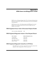
QLLC Mapping
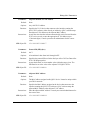
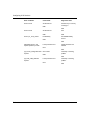
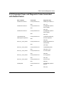
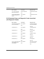
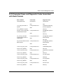
The QLLC software matches the MAC address that DLSw recognizes to the
X.121 address that X.25 recognizes. It also translates the data into a format that
the receiving X.25 device can comprehend.
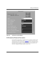
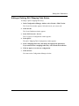
To use QLLC, you must assign a virtual MAC address to the X.25 device, and
map that MAC address to the device’s X.121 address. You must also assign a
virtual X.121 address to the DLSw device, and map that address to the DLSw
device’s MAC address. This mapping sets a path for forwarding data between an
X.25 VC to and a specific remote DLSw device. QLLC requires one mapping
entry for each VC.
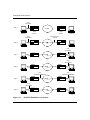
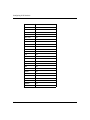
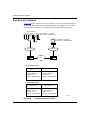
Appendix B, “QLLC Configuration Examples,” shows examples of QLLC
network topologies.
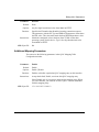
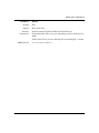
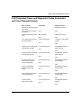
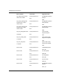
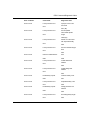
Adjacent and Partner Devices
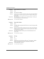
Bay Networks QLLC uses the terms adjacent and partner to describe the X.121
and MAC addresses that map to each other. These terms are relative to the
interface that runs the QLLC/X.25 software.
The Adjacent X.121 DTE/DCE device connects to the interface that is running the
QLLC/X.25 software, either directly or indirectly. It maps to that device’s
Adjacent MAC address.
The Partner X.121 DTE/DCE device connects through the DLSw network. It
maps to that device’s Partner MAC Address.
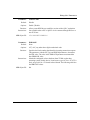
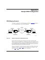
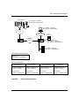
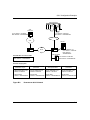
In Figure B-1, for example, Router A connects to the SNA mainframe through the
X.25 network, so the mainframe is an adjacent device. The PC, the 3174 control
unit, and the AS400 are partner devices because they connect through the DLSw
network, and not through the X.25 network.
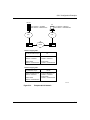
In Figure B-4 of Appendix B, Router A connects to the SNA mainframe through a
token ring network, so it is a partner device. Router A connects to the PC through
the X.25 network, so the PC is an adjacent device. The mainframe is an adjacent
device for Router B, because they connect through the X.25 network. The PC is a
partner device for Router B.
114059 Rev. B
1-21