1
BayRS Version 14.00
Part No. 309249-14.00 Rev 00
September 1999
4401 Great America Parkway
Santa Clara, CA 95054
Configuring MPOA and NHRP
Services
Copyright © 1999 Nortel Networks
All rights reserved. Printed in the USA. September 1999.
The information in this document is subject to change without notice. The statements, configurations, technical data,
and recommendations in this document are believed to be accurate and reliable, but are presented without express or
implied warranty. Users must take full responsibility for their applications of any products specified in this document.
The information in this document is proprietary to Nortel Networks NA Inc.
The software described in this document is furnished under a license agreement and may only be used in accordance
with the terms of that license. A summary of the Software License is included in this document.
Trademarks
NORTEL NETWORKS is a trademark of Nortel Networks.
AN, BCN, BLN, BN, and Bay Networks are registered trademarks and Advanced Remote Node, ANH, ARN, ASN,
BayRS, BCC, and System 5000 are trademarks of Nortel Networks.
All other trademarks and registered trademarks are the property of their respective owners.
Restricted Rights Legend
Use, duplication, or disclosure by the United States Government is subject to restrictions as set forth in subparagraph
(c)(1)(ii) of the Rights in Technical Data and Computer Software clause at DFARS 252.227-7013.
Notwithstanding any other license agreement that may pertain to, or accompany the delivery of, this computer
software, the rights of the United States Government regarding its use, reproduction, and disclosure are as set forth in
the Commercial Computer Software-Restricted Rights clause at FAR 52.227-19.
Statement of Conditions
In the interest of improving internal design, operational function, and/or reliability, Nortel Networks NA Inc. reserves
the right to make changes to the products described in this document without notice.
Nortel Networks NA Inc. does not assume any liability that may occur due to the use or application of the product(s)
or circuit layout(s) described herein.
Portions of the code in this software product may be Copyright © 1988, Regents of the University of California. All
rights reserved. Redistribution and use in source and binary forms of such portions are permitted, provided that the
above copyright notice and this paragraph are duplicated in all such forms and that any documentation, advertising
materials, and other materials related to such distribution and use acknowledge that such portions of the software were
developed by the University of California, Berkeley. The name of the University may not be used to endorse or
promote products derived from such portions of the software without specific prior written permission.
SUCH PORTIONS OF THE SOFTWARE ARE PROVIDED “AS IS” AND WITHOUT ANY EXPRESS OR
IMPLIED WARRANTIES, INCLUDING, WITHOUT LIMITATION, THE IMPLIED WARRANTIES OF
MERCHANTABILITY AND FITNESS FOR A PARTICULAR PURPOSE.
In addition, the program and information contained herein are licensed only pursuant to a license agreement that
contains restrictions on use and disclosure (that may incorporate by reference certain limitations and notices imposed
by third parties).
ii
309249-14.00 Rev 00
Nortel Networks NA Inc. Software License Agreement
NOTICE: Please carefully read this license agreement before copying or using the accompanying software or
installing the hardware unit with pre-enabled software (each of which is referred to as “Software” in this Agreement).
BY COPYING OR USING THE SOFTWARE, YOU ACCEPT ALL OF THE TERMS AND CONDITIONS OF
THIS LICENSE AGREEMENT. THE TERMS EXPRESSED IN THIS AGREEMENT ARE THE ONLY TERMS
UNDER WHICH NORTEL NETWORKS WILL PERMIT YOU TO USE THE SOFTWARE. If you do not accept
these terms and conditions, return the product, unused and in the original shipping container, within 30 days of
purchase to obtain a credit for the full purchase price.
1. License Grant. Nortel Networks NA Inc. (“Nortel Networks”) grants the end user of the Software (“Licensee”) a
personal, nonexclusive, nontransferable license: a) to use the Software either on a single computer or, if applicable, on
a single authorized device identified by host ID, for which it was originally acquired; b) to copy the Software solely
for backup purposes in support of authorized use of the Software; and c) to use and copy the associated user manual
solely in support of authorized use of the Software by Licensee. This license applies to the Software only and does not
extend to Nortel Networks Agent software or other Nortel Networks software products. Nortel Networks Agent
software or other Nortel Networks software products are licensed for use under the terms of the applicable Nortel
Networks NA Inc. Software License Agreement that accompanies such software and upon payment by the end user of
the applicable license fees for such software.
2. Restrictions on use; reservation of rights. The Software and user manuals are protected under copyright laws.
Nortel Networks and/or its licensors retain all title and ownership in both the Software and user manuals, including
any revisions made by Nortel Networks or its licensors. The copyright notice must be reproduced and included with
any copy of any portion of the Software or user manuals. Licensee may not modify, translate, decompile, disassemble,
use for any competitive analysis, reverse engineer, distribute, or create derivative works from the Software or user
manuals or any copy, in whole or in part. Except as expressly provided in this Agreement, Licensee may not copy or
transfer the Software or user manuals, in whole or in part. The Software and user manuals embody Nortel Networks’
and its licensors’ confidential and proprietary intellectual property. Licensee shall not sublicense, assign, or otherwise
disclose to any third party the Software, or any information about the operation, design, performance, or
implementation of the Software and user manuals that is confidential to Nortel Networks and its licensors; however,
Licensee may grant permission to its consultants, subcontractors, and agents to use the Software at Licensee’s facility,
provided they have agreed to use the Software only in accordance with the terms of this license.
3. Limited warranty. Nortel Networks warrants each item of Software, as delivered by Nortel Networks and properly
installed and operated on Nortel Networks hardware or other equipment it is originally licensed for, to function
substantially as described in its accompanying user manual during its warranty period, which begins on the date
Software is first shipped to Licensee. If any item of Software fails to so function during its warranty period, as the sole
remedy Nortel Networks will at its discretion provide a suitable fix, patch, or workaround for the problem that may be
included in a future Software release. Nortel Networks further warrants to Licensee that the media on which the
Software is provided will be free from defects in materials and workmanship under normal use for a period of 90 days
from the date Software is first shipped to Licensee. Nortel Networks will replace defective media at no charge if it is
returned to Nortel Networks during the warranty period along with proof of the date of shipment. This warranty does
not apply if the media has been damaged as a result of accident, misuse, or abuse. The Licensee assumes all
responsibility for selection of the Software to achieve Licensee’s intended results and for the installation, use, and
results obtained from the Software. Nortel Networks does not warrant a) that the functions contained in the software
will meet the Licensee’s requirements, b) that the Software will operate in the hardware or software combinations that
the Licensee may select, c) that the operation of the Software will be uninterrupted or error free, or d) that all defects
in the operation of the Software will be corrected. Nortel Networks is not obligated to remedy any Software defect that
cannot be reproduced with the latest Software release. These warranties do not apply to the Software if it has been (i)
altered, except by Nortel Networks or in accordance with its instructions; (ii) used in conjunction with another
vendor’s product, resulting in the defect; or (iii) damaged by improper environment, abuse, misuse, accident, or
negligence. THE FOREGOING WARRANTIES AND LIMITATIONS ARE EXCLUSIVE REMEDIES AND ARE
IN LIEU OF ALL OTHER WARRANTIES EXPRESS OR IMPLIED, INCLUDING WITHOUT LIMITATION ANY
WARRANTY OF MERCHANTABILITY OR FITNESS FOR A PARTICULAR PURPOSE. Licensee is responsible
309249-14.00 Rev 00
iii
for the security of its own data and information and for maintaining adequate procedures apart from the Software to
reconstruct lost or altered files, data, or programs.
4. Limitation of liability. IN NO EVENT WILL NORTEL NETWORKS OR ITS LICENSORS BE LIABLE FOR
ANY COST OF SUBSTITUTE PROCUREMENT; SPECIAL, INDIRECT, INCIDENTAL, OR CONSEQUENTIAL
DAMAGES; OR ANY DAMAGES RESULTING FROM INACCURATE OR LOST DATA OR LOSS OF USE OR
PROFITS ARISING OUT OF OR IN CONNECTION WITH THE PERFORMANCE OF THE SOFTWARE, EVEN
IF NORTEL NETWORKS HAS BEEN ADVISED OF THE POSSIBILITY OF SUCH DAMAGES. IN NO EVENT
SHALL THE LIABILITY OF NORTEL NETWORKS RELATING TO THE SOFTWARE OR THIS AGREEMENT
EXCEED THE PRICE PAID TO NORTEL NETWORKS FOR THE SOFTWARE LICENSE.
5. Government Licensees. This provision applies to all Software and documentation acquired directly or indirectly by
or on behalf of the United States Government. The Software and documentation are commercial products, licensed on
the open market at market prices, and were developed entirely at private expense and without the use of any U.S.
Government funds. The license to the U.S. Government is granted only with restricted rights, and use, duplication, or
disclosure by the U.S. Government is subject to the restrictions set forth in subparagraph (c)(1) of the Commercial
Computer Software––Restricted Rights clause of FAR 52.227-19 and the limitations set out in this license for civilian
agencies, and subparagraph (c)(1)(ii) of the Rights in Technical Data and Computer Software clause of DFARS
252.227-7013, for agencies of the Department of Defense or their successors, whichever is applicable.
6. Use of Software in the European Community. This provision applies to all Software acquired for use within the
European Community. If Licensee uses the Software within a country in the European Community, the Software
Directive enacted by the Council of European Communities Directive dated 14 May, 1991, will apply to the
examination of the Software to facilitate interoperability. Licensee agrees to notify Nortel Networks of any such
intended examination of the Software and may procure support and assistance from Nortel Networks.
7. Term and termination. This license is effective until terminated; however, all of the restrictions with respect to
Nortel Networks’ copyright in the Software and user manuals will cease being effective at the date of expiration of the
Nortel Networks copyright; those restrictions relating to use and disclosure of Nortel Networks’ confidential
information shall continue in effect. Licensee may terminate this license at any time. The license will automatically
terminate if Licensee fails to comply with any of the terms and conditions of the license. Upon termination for any
reason, Licensee will immediately destroy or return to Nortel Networks the Software, user manuals, and all copies.
Nortel Networks is not liable to Licensee for damages in any form solely by reason of the termination of this license.
8. Export and Re-export. Licensee agrees not to export, directly or indirectly, the Software or related technical data
or information without first obtaining any required export licenses or other governmental approvals. Without limiting
the foregoing, Licensee, on behalf of itself and its subsidiaries and affiliates, agrees that it will not, without first
obtaining all export licenses and approvals required by the U.S. Government: (i) export, re-export, transfer, or divert
any such Software or technical data, or any direct product thereof, to any country to which such exports or re-exports
are restricted or embargoed under United States export control laws and regulations, or to any national or resident of
such restricted or embargoed countries; or (ii) provide the Software or related technical data or information to any
military end user or for any military end use, including the design, development, or production of any chemical,
nuclear, or biological weapons.
9. General. If any provision of this Agreement is held to be invalid or unenforceable by a court of competent
jurisdiction, the remainder of the provisions of this Agreement shall remain in full force and effect. This Agreement
will be governed by the laws of the state of California.
Should you have any questions concerning this Agreement, contact Nortel Networks, 4401 Great America Parkway,
P.O. Box 58185, Santa Clara, California 95054-8185.
LICENSEE ACKNOWLEDGES THAT LICENSEE HAS READ THIS AGREEMENT, UNDERSTANDS IT, AND
AGREES TO BE BOUND BY ITS TERMS AND CONDITIONS. LICENSEE FURTHER AGREES THAT THIS
AGREEMENT IS THE ENTIRE AND EXCLUSIVE AGREEMENT BETWEEN NORTEL NETWORKS AND
LICENSEE, WHICH SUPERSEDES ALL PRIOR ORAL AND WRITTEN AGREEMENTS AND
COMMUNICATIONS BETWEEN THE PARTIES PERTAINING TO THE SUBJECT MATTER OF THIS
AGREEMENT. NO DIFFERENT OR ADDITIONAL TERMS WILL BE ENFORCEABLE AGAINST NORTEL
NETWORKS UNLESS NORTEL NETWORKS GIVES ITS EXPRESS WRITTEN CONSENT, INCLUDING AN
EXPRESS WAIVER OF THE TERMS OF THIS AGREEMENT.
iv
309249-14.00 Rev 00
Contents
Preface
Before You Begin .............................................................................................................xiii
Text Conventions .............................................................................................................xiv
Acronyms .........................................................................................................................xvi
Hard-Copy Technical Manuals ....................................................................................... xviii
How to Get Help ............................................................................................................ xviii
Chapter 1
Understanding MPOA and NHRP
ATM General Information ................................................................................................1-1
Multi-Protocol over ATM ..................................................................................................1-2
MPOA Logical Components .....................................................................................1-3
MPOA Basic Elements .............................................................................................1-4
Establishing a Network Cut-Through .......................................................................1-5
NHRP .............................................................................................................................1-7
For More Information ......................................................................................................1-8
Where to Go Next ...........................................................................................................1-9
Chapter 2
Starting MPOA and NHRP Services
Starting Configuration Tools ...........................................................................................2-1
Starting the MPOA Server ..............................................................................................2-2
Creating an MPOA Service Record .........................................................................2-2
Adding an MPOA Server ..........................................................................................2-4
Starting NHRP on an ATM LEC, PVC, or Classical IP Service ......................................2-5
Starting NHRP on an ATM LEC Service ..................................................................2-6
Starting NHRP on an ATM PVC Service ................................................................2-11
Starting NHRP on an ATM Classical IP (RFC 1577 SVC) Service ........................2-14
Where to Go Next .........................................................................................................2-16
309249-14.00 Rev 00
v
Chapter 3
Customizing MPOA Services
Disabling and Reenabling an MPOA Service .................................................................3-2
Setting the MPS Address Generating Mode ...................................................................3-3
Specifying an MPS Control ATM Address ......................................................................3-5
Network Prefix ..........................................................................................................3-5
User Suffix ................................................................................................................3-6
Disabling and Reenabling MPOA Servers ......................................................................3-8
Specifying the MPS Configuration Mode ......................................................................3-10
Specifying a LECS ATM Address .................................................................................3-11
Network Prefix ........................................................................................................3-12
User Suffix ..............................................................................................................3-12
Configuring a Unique Selector Byte for an MPS Address ............................................3-14
Defining MPS Timer Values ..........................................................................................3-16
Setting the Transmission Interval for MPOA Keepalive Packets .............................3-17
Setting the Valid Lifetime for Keepalive Packets .....................................................3-18
Setting the Initial Retry Time ..................................................................................3-19
Setting the Maximum Retry Time ...........................................................................3-21
Setting the Time to Wait for Responses to Resolution Requests ...........................3-22
Setting the Valid Interval for Replies to Resolution Requests ................................3-23
Defining MPS Cache Values ........................................................................................3-25
Setting the Initial Cache Size .................................................................................3-25
Setting the Maximum Cache Size ..........................................................................3-26
Deleting MPOA Servers ...............................................................................................3-28
Deleting an MPOA Service Record ..............................................................................3-29
Where to Go Next .........................................................................................................3-31
Chapter 4
Customizing NHRP Services
Accessing NHRP Client and Server Global Parameters ................................................4-2
Disabling NHRP on an LEC or PVC or Classical IP Service ..........................................4-4
Deleting NHRP from an LEC or PVC or SVC Service ....................................................4-6
Deleting NHRP Globally .................................................................................................4-7
Where to Go Next ...........................................................................................................4-8
vi
309249-14.00 Rev 00
Appendix A
Site Manager Parameters
Accessing ATM Parameters ........................................................................................... A-1
Accessing ATM MPOA Parameters Through a Window Path ................................. A-2
Accessing ATM MPOA and NHRP Parameters Through a Menu Path ................... A-2
MPOA Service Parameters ............................................................................................ A-3
MPOA Server (MPS) Parameters .................................................................................. A-5
MPS Add Parameters .............................................................................................. A-5
MPS Operational Parameters ................................................................................. A-7
NHRP Global Parameters ............................................................................................ A-14
NHRP Interface Parameters ........................................................................................ A-19
Appendix B
BCC Parameters
MPOA Service Record Parameters ............................................................................... B-2
MPS Parameters ........................................................................................................... B-4
MPOA Server Parameters ............................................................................................. B-8
NHRP Global Parameters .............................................................................................. B-9
NHRP Interface Parameter .......................................................................................... B-13
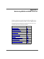
Appendix C
Monitoring MPOA and NHRP Services
Online Help for show Commands .................................................................................. C-2
show mpoa caches ........................................................................................................ C-3
show mpoa caches all ............................................................................................. C-3
show mpoa caches egress ...................................................................................... C-4
show mpoa caches ingress ..................................................................................... C-6
show mpoa server ......................................................................................................... C-7
show mpoa server configuration ............................................................................. C-7
show mpoa server stats .......................................................................................... C-9
show nhrp .................................................................................................................... C-12
show nhrp client configuration ............................................................................... C-12
show nhrp client stats ........................................................................................... C-13
show nhrp interfaces ............................................................................................. C-14
show nhrp server configuration ............................................................................. C-15
show nhrp server stats .......................................................................................... C-15
309249-14.00 Rev 00
vii
Appendix D
Example Configuration
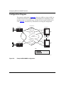
Configuration Diagram ................................................................................................... D-2
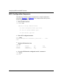
BCC Configuration Sequence ....................................................................................... D-4
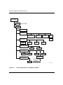
Appendix E
BCC Configuration Tree
for MPOA and NHRP
viii
309249-14.00 Rev 00
Figures
Figure 1-1.
ATM Zero-Hop (Cut-Through) Routing .....................................................1-2
Figure 1-2.
MPOA with Cut-Through VC ....................................................................1-6
Figure 2-1.
Mapping an MPS to an LEC Service .......................................................2-9
Figure D-1.
Example MPOA/NHRP Configuration ..................................................... D-2
Figure E-1.
BCC Configuration Tree for MPOA and NHRP ....................................... E-2
309245-14.00 Rev 00
ix
Tables
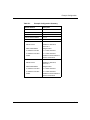
Table D-1.
Example Configuration Summary ........................................................... D-3
309249-14.00 Rev 00
xi
Preface
This guide describes Nortel Networks implementation of Multi-Protocol over
ATM (MPOA) and Next Hop Resolution Protocol (NHRP) services, and what you
do to start and customize these services on a Nortel Networks™ router.
You can use the Bay Command Console (BCC™) or Site Manager to configure
MPOA and NHRP on a router. In this guide, you will find instructions for using
both the BCC and Site Manager. Use Site Manager to support any feature not
support by the BCC.
Before You Begin
Before using this guide, you must complete the following procedures. For a new
router:
•
Install the router (see the installation guide that came with your router).
•
Connect the router to the network and create a pilot configuration file (see
Quick-Starting Routers, Configuring BayStack Remote Access, or Connecting
ASN Routers to a Network).
Make sure that you are running the latest version of Nortel Networks BayRS™ and
Site Manager software. For information about upgrading BayRS and Site
Manager, see the upgrading guide for your version of BayRS.
309249-14.00 Rev 00
xiii
Configuring MPOA and NHRP Services
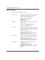
Text Conventions
This guide uses the following text conventions:
angle brackets (< >)
Indicate that you choose the text to enter based on the
description inside the brackets. Do not type the
brackets when entering the command.
Example: If the command syntax is:
ping <ip_address>, you enter:
ping 192.32.10.12
bold text
Indicates command names and options and text that
you need to enter.
Example: Enter show ip {alerts | routes}.
Example: Use the dinfo command.
braces ({})
Indicate required elements in syntax descriptions
where there is more than one option. You must choose
only one of the options. Do not type the braces when
entering the command.
Example: If the command syntax is:
show ip {alerts | routes}, you must enter either:
show ip alerts or show ip routes, but not both.
brackets ([ ])
Indicate optional elements in syntax descriptions. Do
not type the brackets when entering the command.
Example: If the command syntax is:
show ip interfaces [-alerts], you can enter either:
show ip interfaces or show ip interfaces -alerts.
ellipsis points (. . . )
Indicate that you repeat the last element of the
command as needed.
Example: If the command syntax is:
ethernet/2/1 [<parameter> <value>] . . . , you enter
ethernet/2/1 and as many parameter-value pairs as
needed.
xiv
309249-14.00 Rev 00
Preface
italic text
Indicates file and directory names, new terms, book
titles, and variables in command syntax descriptions.
Where a variable is two or more words, the words are
connected by an underscore.
Example: If the command syntax is:
show at <valid_route>
valid_route is one variable and you substitute one value
for it.
screen text
Indicates system output, for example, prompts and
system messages.
Example: Set Trap Monitor Filters
separator ( > )
Shows menu paths.
Example: Protocols > IP identifies the IP option on the
Protocols menu.
vertical line ( | )
Separates choices for command keywords and
arguments. Enter only one of the choices. Do not type
the vertical line when entering the command.
Example: If the command syntax is:
show ip {alerts | routes}, you enter either:
show ip alerts or show ip routes, but not both.
309249-14.00 Rev 00
xv
Configuring MPOA and NHRP Services
Acronyms
This guide uses the following acronyms:
xvi
AAL
ATM adaptation layer
AFI
authority and format identifier
ARE
ATM Routing Engine
ARP
Address Resolution Protocol
ATM
asynchronous transfer mode
B-ISDN
Broadband Integrated Services Digital Network
CSU
channel service unit
DCE
data communication equipment
DSU
data service unit
DTE
data terminal equipment
ELAN
emulated local area network
IETF
Internet Engineering Task Force
ILI
Intelligent Link Interface
ILMI
Interim Local Management Interface
IP
Internet Protocol
LANE
local area network emulation
LE
LAN emulation
LEC
LAN emulation client
LECS
LAN emulation configuration server
LER
label edge router
LES
LAN emulation server
LLC
Logical Link Control
MAC
media access control
MIB
management information base
MPC
MPOA client
MPLS
Multiprotocol Label Switching
309249-14.00 Rev 00
Preface
MPOA
Multi-Protocol over ATM
MPS
MPOA server
MTU
maximum transmission unit
NHRP
Next Hop Resolution Protocol
OC-3
Optical Carrier-level 3
OSPF
Open Shortest Path First
PDN
Public Data Network
PDU
protocol data unit
PHY
physical [layer]
PMD
physical medium dependent
PT
payload type
PVC
permanent virtual circuit
RIP
Routing Information Protocol
SAAL
signaling AAL
SAP
service access point
SAR
segmentation and reassembly
SMDS
Switched Multimegabit Data Service
SNAP
Subnetwork Access Protocol
SNMP
Simple Network Management Protocol
SONET/SDH
Synchronous Optical Network/Synchronous Digital Hierarchy
SPE
synchronous payload envelope
SRM
System Resource Module
SSCOP
Service Specific Connection Oriented Protocol
SSCS
service specific convergence sublayer
SVC
switched virtual circuit
UNI
user-to-network interface
VC
virtual circuit
VCC
virtual channel connection
VCI
virtual channel identifier
309249-14.00 Rev 00
xvii
Configuring MPOA and NHRP Services
VCL
virtual channel link
VPC
virtual path connection
VPI
virtual path identifier
WAN
wide area network
Hard-Copy Technical Manuals
You can print selected technical manuals and release notes free, directly from the
Internet. Go to support.baynetworks.com/library/tpubs/. Find the product for
which you need documentation. Then locate the specific category and model or
version for your hardware or software product. Using Adobe Acrobat Reader, you
can open the manuals and release notes, search for the sections you need, and print
them on most standard printers. You can download Acrobat Reader free from the
Adobe Systems Web site, www.adobe.com.
You can purchase selected documentation sets, CDs, and technical publications
through the collateral catalog. The catalog is located on the World Wide Web at
support.baynetworks.com/catalog.html and is divided into sections arranged
alphabetically:
•
The “CD ROMs” section lists available CDs.
•
The “Guides/Books” section lists books on technical topics.
•
The “Technical Manuals” section lists available printed documentation sets.
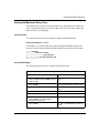
How to Get Help
If you purchased a service contract for your Nortel Networks product from a
distributor or authorized reseller, contact the technical support staff for that
distributor or reseller for assistance.
If you purchased a Nortel Networks service program, contact one of the following
Nortel Networks Technical Solutions Centers:
xviii
Technical Solutions Center
Telephone Number
Billerica, MA
800-2LANWAN (800-252-6926)
Santa Clara, CA
800-2LANWAN (800-252-6926)
309249-14.00 Rev 00
Preface
Technical Solutions Center
Telephone Number
Valbonne, France
33-4-92-96-69-68
Sydney, Australia
61-2-9927-8800
Tokyo, Japan
81-3-5402-7041
309249-14.00 Rev 00
xix
Chapter 1
Understanding MPOA and NHRP
This chapter describes the concepts underlying Multi-protocol over ATM (MPOA)
and Next-Hop Resolution Protocol (NHRP) and, where appropriate, the specific
ways in which Nortel Networks implements MPOA and NHRP functionality on
its routers. It contains the following information:
Topic
Page
ATM General Information
1-1
Multi-Protocol over ATM
1-2
NHRP
1-7
For More Information
1-8
Where to Go Next
1-9
ATM General Information
Asynchronous transfer mode (ATM) is a connection-oriented, cell-based
technology that relays traffic across a Broadband Integrated Services Digital
Network (B-ISDN). ATM provides a cost-effective way of transmitting voice,
video, and data across a network. For more information about ATM, see
Configuring ATM Services.
309249-14.00 Rev 00
1-1
Configuring MPOA and NHRP Services
Multi-Protocol over ATM
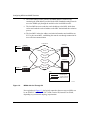
As defined by the ATM Forum, Multi-Protocol over ATM (MPOA) maps routed
and bridged traffic flows to ATM SVCs, thereby removing many performance
limitations imposed by the multihop routing of individual packets. This technique
of mapping identifiable traffic flows to virtual channels creates network
“shortcuts” between source and destination clients, and is generally referred to as
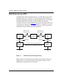
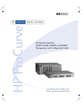
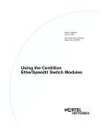
cut-through or zero-hop routing. Figure 1-1 shows how users on LAN 1 or LAN 2
can communicate efficiently over an independent layer 2 (ATM) virtual channel,
established by means of MPOA and NHRP negotiations.
ATM ELAN, PVC
or RFC 1577 SVC
MPOA server 1
(MPS)
NHRP
MPOA
ATM ELAN
MPOA client 1
(MPC)
ATM ELAN, PVC
or RFC 1577 SVC
MPOA servers
(MPSs)
NHRP
MPOA server n
(MPS)
ATM ELAN
MPOA
Cut-through (zero-hop) route (ATM SVC)
Established through MPOA/NHRP negotiations
LAN 1
MPOA client 2
(MPC)
LAN 2
BCC0029A
Figure 1-1.
ATM Zero-Hop (Cut-Through) Routing
MPOA supports communication between an MPOA client (MPC), typically an
ATM edge device or switch, and its MPOA server (MPS), typically a router.
NHRP supports communication between MPSs.
1-2
309249-14.00 Rev 00
Understanding MPOA and NHRP
Although the connection between any two MPSs can be supported by an ATM
PVC, RFC 1577 SVC (ATM Classical IP), or emulated LAN (ATM LANE), the
connection between any MPC and its MPS must always be supported by an
ELAN, as shown in Figure 1-1 on page 1-2.
Cut-through routing is based on the fact that, in most cases, data transfer occurs at
a steady rate of flow. For example, data or file transfer from one legacy Ethernet
LAN to a remote counterpart usually involves multiple frames. A file transfer of
approximately 45 KB requires about 30 Ethernet frames, all addressed to the same
destination.
In an MPOA environment, it is possible to:
•
Identify, from the address field in the first frame of a data/file transfer, the
recipient of that data or file.
•
Establish an SVC to the recipient.
The software then disassembles all 30 or so frames into approximately 900 ATM
cells and transmitts them to the recipient by way of the virtual channel provided
by the SVC.
Network performance improves as the cells follow a predetermined direct path, in
contrast to the hop-by-hop routing of the Ethernet frames. Network performance
improves markedly in the case of steady-stream deterministic data flows, such as
video.
MPOA Logical Components
MPOA operations are based on logical components, which can be implemented in
various configurations of hardware and software. MPOA logical components
include the following:
•
MPOA clients
An MPOA client (MPC) resides in each ATM edge device (for example, an
ATM switch) served by an MPOA router. BayRS does not provide MPC
functionality. The primary function of the MPC is to act, in ATM terminology,
as an ingress or egress point for traffic establishing and subsequently using
network cut-throughs.
309249-14.00 Rev 00
1-3
Configuring MPOA and NHRP Services
The MPC monitors traffic flows between a local source and remote
destinations. When traffic volume between a source and a destination exceeds
a preconfigured threshold level (for example x packets to the same network
layer address in y seconds), the MPC attempts to set up an SVC between the
source and destination workstations.
In attempting to set up an SVC, the MPC first looks in a local cache of
network layer-to-ATM address mappings. If the MPC finds the destination
address in its local cache, it immediately begins to establish the SVC. If it fails
to locate the destination address in the local cache, it generates an MPOA
address resolution request to an adjacent MPOA server.
•
MPOA routers
Each MPOA router that serves MPCs, directly or indirectly, includes a
collection of logical functions that map network layer addresses to ATM
addresses. Each MPOA router maintains tables of adjacent network layer (IP),
MAC layer, and ATM addresses, in addition to standard routing tables derived
from a routing protocol (generally OSPF or RIP).
MPOA routers communicate over NHRP to map network layer addresses to
ATM addresses. BayRS provides MPOA router functionality to map IP
addresses to their ATM counterparts.
•
MPOA servers
The MPOA server (MPS) is a logical function that mediates between local
MPCs and the MPOA router. It receives MPOA address resolution requests
from MPCs and passes them to the MPOA routing function. The MPOA
router, using NHRP, resolves the address and passes the requested ATM
address back to the MPS. The MPS, in turn, forwards the resolved address to
the requesting MPC. BayRS provides MPOA server functionality.
MPOA Basic Elements
MPOA services provided by each Nortel Networks router depend on the existence
of:
1-4
•
An ATM emulated LAN (using LANE) between each MPC and its MPS.
•
An ATM emulated LAN, ATM Classical IP (RFC 1577 SVC), or an ATM
PVC between any two MPSs. (See Figure 1-1 on page 1-2.)
•
NHRP to resolve ATM and IP source and destination addresses.
•
IP to route NHRP packets and other traffic between MPSs.
309249-14.00 Rev 00
Understanding MPOA and NHRP
For more information about
Go to
IP
Configuring IP Services
LANE
Configuring ATM Services
NHRP
“NHRP” on page 1-7
Establishing a Network Cut-Through
MPOA components and elements function together to establish an SVC between a
source host and a destination host, as follows:
1.
A local MPC monitors traffic flow and maintains a count of packets addressed
over a specific interval to remote hosts. When the count exceeds a threshold
value, the MPC attempts to establish an SVC to the host.
To establish the virtual connection, the MPC needs the ATM address of the
host.
2.
The MPC first checks a local address resolution cache to map the known
network layer address with an ATM equivalent.
3.
If the cache search fails, the MPC issues an MPOA resolution request to the
local MPS function resident on the adjacent router.
4.
The local MPS hands the resolution request to the MPOA router component.
5.
The MPOA router generates an NHRP address resolution request for the ATM
address of the destination host. Standard routing protocols move the NHRP
request through the network toward the destination host. Eventually, the
NHRP request reaches the egress router, that is, the router that serves the
target host.
6.
The egress router forwards the request to its MPS entity.
7.
The remote MPS provides the ATM address of the destination host to its
NHRP entity.
If the destination host is connected to a legacy LAN, the MPS provides the
ATM address of the router that connects to the legacy LAN. If the destination
host is ATM-attached, the MPS provides the ATM address of the destination
host.
309249-14.00 Rev 00
1-5
Configuring MPOA and NHRP Services
8.
The remote MPOA router generates an NHRP address resolution reply
containing the ATM address provided by the MPS. Standard routing protocols
move the NHRP reply through the network to the local MPOA router.
9.
The local MPOA router sends the resolved address to the MPS, which then
caches and sends the resolved address to the MPC that initiated the resolution
process.
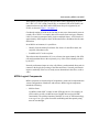
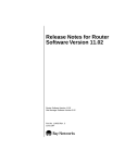
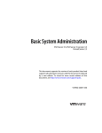
10. The local MPC caches the address resolution information and establishes an
SVC to the remote MPC, establishing the network cut-through connection for
more efficient communication.
ATM network
ATM MPS
ATM MPC
10BASE-T
ELAN 1
ELAN 2
ATM MPS
ELAN 3
ELAN 4
ATM MPC
10BASE-T
Key
Cut-through VC
Logical connection
NHRP control VC
ATM0055A
Figure 1-2.
MPOA with Cut-Through VC
Note again that in Figure 1-2, the logical connection between any two MPSs can
be an ATM PVC or RFC 1577 SVC (ATM Classical IP) instead of an ELAN,
depending on your network topology requirements.
1-6
309249-14.00 Rev 00
Understanding MPOA and NHRP
NHRP
NHRP is an address resolution protocol described in Internet RFC 2332.
As defined by the RFC, NHRP provides address resolution services by mapping
“internetworking layer addresses to NBMA subnetwork addresses.” As
implemented by Nortel Networks, NHRP resolves IP to ATM addresses.
The IETF draft specifies behavior for NHRP clients and NHRP servers.
•
The NHRP client (NHC) generates NHRP address resolution requests on
behalf of applications such as a local MPS.
•
The NHRP server (NHS) responds to NHRP address resolution requests by
generating NHRP address resolution replies. For this purpose, the NHS
maintains a next-hop cache.
NHRP supports address resolution using seven formatted message types.
•
NHRP resolution request
An NHRP resolution request is generated by an NHC and routed through the
ATM topology. Functionally equivalent to a standard ARP request, it contains
the layer 3 and layer 2 address of the originator, the layer 3 address of the
target destination, and a blank field reserved for the layer 2 address of the
target. As implemented by Nortel Networks, the NHRP resolution request
contains the IP and ATM addresses of the originator and the IP address of the
target.
•
NHRP resolution reply
An NHRP resolution reply is generated by an NHS in response to an NHRP
resolution request. Like an NHRP resolution request, it is routed through the
ATM topology. It is functionally equivalent to a standard ARP response in that
it replicates the information in the NHRP resolution request and supplies the
requested layer 2 (ATM) address.
•
NHRP registration request
An NHRP registration request is generated by an NHC and directed toward
the local NHS. The NHRP registration request is used to register address
mapping data gathered by the NHC with the NHS. The NHS places mapping
data in its next-hop cache.
309249-14.00 Rev 00
1-7
Configuring MPOA and NHRP Services
•
NHRP registration reply
An NHRP registration reply is generated by an NHS in response to an NHRP
registration request. It provides positive or negative acknowledgment of data
receipt.
•
NHRP purge request
An NHRP purge request can be generated by either an NHC or an NHS. It
requests the recipient to delete previously cached information that has become
invalid.
•
NHRP purge reply
An NHRP purge reply is generated by either an NHC or an NHS in response
to an NHRP purge request. It provides positive acknowledgment of data
receipt.
•
NHRP error indication
An NHRP error indication can be generated by either an NHC or an NHS. It
conveys error status to the sender of an NHRP message.
For More Information
For more information about MPOA and NHRP, refer to the following documents:
Heinanen, J. Multiprotocol Encapsulation over ATM Adaptation Layer 5.
RFC 1483. Network Working Group. July 1993.
Cole, B., N. Doraswamy, D. Katz, J. Luciani, D. Piscitello. NBMA Next Hop
Resolution Protocol (NHRP). RFC 2332. April 1998.
1-8
309249-14.00 Rev 00
Understanding MPOA and NHRP
Where to Go Next
Use the following table to determine where to go next.
If you want to
Go to
Learn about ATM and PVCs.
Configuring ATM Services
Learn about LAN emulation.
Start MPOA and NHRP services.
Chapter 2
Change default settings for MPOA server parameters.
Chapter 3
Change default settings for NHRP client or server
parameters.
Chapter 4
Obtain information about Site Manager parameters.
Appendix A
Obtain information about BCC parameters.
Appendix B
Monitor ATM using the BCC show commands.
Appendix C
Review an example MPOA/NHRP configuration
sequence.
Appendix D
Review the BCC configuration tree for MPOA and NHRP Appendix E
services.
309249-14.00 Rev 00
1-9
Chapter 2
Starting MPOA and NHRP Services
This chapter describes how to create basic MPOA and NHRP configurations by
specifying values for required parameters only, and by accepting default values for
all other parameters.
This chapter contains the following information:
Topic
Page
Starting Configuration Tools
2-1
Starting the MPOA Server
2-2
Starting NHRP on an ATM LEC, PVC, or Classical IP Service
2-5
Where to Go Next
2-16
Starting Configuration Tools
Before configuring MPOA or NHRP services, refer to the following user guides
for instructions on how to start and use the Nortel Networks configuration tool of
your choice.
Configuration Tool
User Guide
Bay Command Console (BCC)
Using the Bay Command Console (BCC)
Site Manager
Configuring and Managing Routers with
Site Manager
309249-14.00 Rev 00
2-1
Configuring MPOA and NHRP Services
Starting the MPOA Server
To start the MPOA server, you must perform the following steps:
1.
Start ATM on the router. (See Configuring ATM Services.)
2.
Configure any ATM PVCs, SVCs (Classical IP), and LAN emulation client
(LEC) services that you need for MPOA/NHRP to operate within your
specific network topology. (See Chapter 1 and Configuring ATM Services.)
Be sure to:
•
Specify LANE data encapsulation for each LEC that you require.
•
Specify LLC-SNAP data encapsulation for each PVC that you require.
•
Configure IP and NHRP on each LEC, PVC, and Classical IP (SVC)
service.
3.
Create an MPOA service record.
4.
Add an MPS to the MPOA service record.
5.
Ensure that a LECS has been configured on your network.
6.
Map any LEC services on the router to the desired local MPS.
Creating an MPOA Service Record
To run an MPOA server over ATM, you must first create an MPOA service record
on an ATM interface. Then you add one or more MPOA servers (MPSs) to the
MPOA service record.You can use the BCC or Site Manager to accomplish this
using default values for all parameters.
Using the BCC
To create an MPOA service record, navigate to the appropriate ATM interface
prompt and enter:
mpoa-service
2-2
309249-14.00 Rev 00
Starting MPOA and NHRP Services
For example, on a System 5000™ router, the following command sequence:
•
Creates an ATM interface on slot 5, module 3, connector 1.
•
Creates an MPOA service on the ATM interface.
stack# atm slot 5 module 3 connector 1
atm/5/3/1# signaling <-- (Signaling must
signaling/5/3/1# back
atm/5/3/1# mpoa-service
mpoa-service/5/3/1#
be enabled for a new ATM interface.)
On a BLN®/BCN® router, the commands are identical, except that you do not
specify a module number for the ATM interface:
box# atm slot 5 connector 1
atm/5/1# signaling
signaling/5/1# back
atm/5/1# mpoa-service
mpoa-service/5/1#
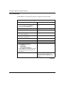
Using Site Manager
To create an MPOA service using Site Manager, complete the following tasks:
Site Manager Procedure
You do this
System responds
1. In the Configuration Manager window,
click on an ATM link module interface (for
example, ATM1).
The Select Connection Type window
opens.
2. Click on ATM.
The Edit ATM Connector window opens.
3. Click on MPOA Server Attributes.
The MPOA Server Parameters window
opens.
4. Click on OK.
The MPOA Service Record window
opens.
5. Go to the next section, “Adding an MPOA
Server,” or go to the next step to exit this
procedure.
6. Click on Done.
You return to the Edit ATM Connector
window.
(continued)
309249-14.00 Rev 00
2-3
Configuring MPOA and NHRP Services
Site Manager Procedure (continued)
You do this
System responds
7. Click on Done.
You return to the Select Connection Type
window.
8. Click on Done.
You return to the Configuration Manager
window.
By default, when you enter and then exit the MPOA Service Record window, you
automatically create and enable the MPOA service record using the default
settings. You need only enter and exit this window one time to create and enable
the MPOA service record. However, for MPOA to operate, you must add at least
one MPS to the service record.
Note: You can have only one MPOA service record per ATM interface.
However, this service record can contain up to four MPSs.
Adding an MPOA Server
You must add at least one MPS to any MPOA service that you create on an ATM
interface. Although not operational until fully configured, an MPS is enabled by
default when you add it to an MPOA service record.
A new MPS must be in the enabled state so that you can map it to one or more
LEC services. Then you can use either the BCC or Site Manager to map each
MPS to a specific LEC service on the router.
Using the BCC
To add an MPS, navigate to the desired MPOA service prompt and enter:
mps mps-name <mps-name>
For example, on a System 5000 router, the following command adds an MPS
named “eastcoast” to an MPOA service:
mpoa-service/5/3/1# mps mps-name eastcoast
mps/eastcoast#
2-4
309249-14.00 Rev 00
Starting MPOA and NHRP Services
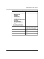
Using Site Manager
To add an MPS to an MPOA service, complete the following tasks:
Site Manager Procedure
You do this
System responds
1. In the Configuration Manager window,
click on an ATM link module interface (for
example, ATM1).
The Select Connection Type window
opens.
2. Click on ATM.
The Edit ATM Connector window opens.
3. Click on MPOA Server Attributes.
The MPOA Server Parameters window
opens.
4. Click on MPS.
The MPS List window opens.
5. Click on Add.
The MPS Configuration Parameters
window opens.
6. Click on OK.
You return to the MPS List window. The
MPS List window shows the added MPS.
7. Repeat steps 5 and 6 to add additional
MPOA servers.
8. Go to the next section, “Starting NHRP on
an ATM LEC, PVC, or Classical IP
Service” or go to the next step to exit this
procedure.
9. Click on Done.
You return to the MPOA Service Record
window.
10. Click on Done.
You return to the Edit ATM Connector
window.
11. Click on Done.
You return to the Select Connection Type
window.
12. Click on Done.
You return to the Configuration Manager
window.
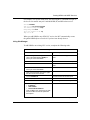
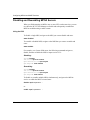
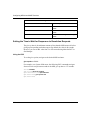
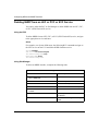
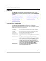
Starting NHRP on an ATM LEC, PVC, or Classical IP Service
Before configuring NHRP on a Nortel Networks router, determine the type of link
between each pair of MPSs in your ATM network. After making this
determination, configure IP, RIP or OSPF, and NHRP on the LEC, PVC, or
Classical IP service (as determined for each MPS-to-MPS link).
309249-14.00 Rev 00
2-5
Configuring MPOA and NHRP Services
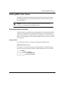
Note: Enabling RIP or OSPF on an LEC, PVC, or Classical IP (SVC) service
is unnecessary if your network already has a routed path between MPSs.
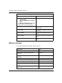
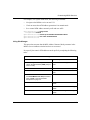
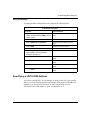
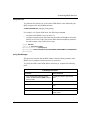
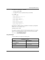
Based on each type of link between two MPSs, proceed as follows:
MPS Link
Service
Go to
Emulated LAN (ELAN)
LEC service
Starting NHRP on an ATM LEC Service
Permanent virtual circuit
(PVC)
PVC service
Starting NHRP on an ATM PVC
Service
Switched virtual circuit
(SVC)
Classical IP service
Starting NHRP on an ATM Classical IP
(RFC 1577 SVC) Service
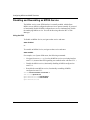
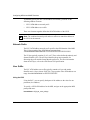
Starting NHRP on an ATM LEC Service
To allow LANE and normally routed traffic to flow through an ATM LEC service
and between MPSs, enable IP and optionally a routing protocol (RIP or OSPF) on
that IP interface.
To allow NHRP address resolution requests and replies to flow through the same
ATM LEC service and between MPSs, you must enable NHRP on that service.
You can use either the BCC or Site Manager to add IP, RIP or OSPF, and NHRP
to an LEC service.
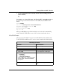
Using the BCC
To add IP, RIP or OSPF, and NHRP to an existing LEC service:
1.
Navigate to the appropriate lec-service prompt and enter:
nhrp
2.
Navigate back to the lec-service prompt, and enter:
ip address <IP_address> mask <subnet_mask>
3.
At the resulting IP interface prompt, add the desired routing protocol
(RIP or OSPF):
rip
2-6
309249-14.00 Rev 00
Starting MPOA and NHRP Services
For example, on a System 5000 router, the following BCC commands navigate to
the lec-service named “newyork” and add NHRP, IP, and RIP to that service:
stack# atm/5/3/1
atm/5/3/1# lec-service/newyork
lec-service/newyork# nhrp
nhrp/newyork# back
ip/1.2.3.4/255.0.0.0# rip
rip/1.2.3.4#
When you add NHRP to any ATM LEC service, the BCC automatically creates
the global NHRP object at root level if you have not already done so.
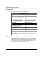
Using Site Manager
To add NHRP to an existing LEC service, complete the following tasks:
Site Manager Procedure
You do this
System responds
1. In the Configuration Manager window,
click on the ATM interface (ATM1) on
which you want to add NHRP.
The Select Connection Type window
opens.
2. Click on ATM.
The Edit ATM Connector window opens.
3. Click on Service Attributes.
The ATM Service Records List window
opens.
4. Click on the ATM LANE service record to
which you want to add NHRP.
5. Click on the Protocols menu in the upper
left hand corner of the window.
6. Choose Add/Delete.
The Select Protocols window opens.
7. Select IP, RIP, and NHRP.
8. Click on OK.
The IP Configuration window opens.
9. Set the following parameters:
• IP Address
• Subnet Mask
• Transmit Bcast Address
Click on Help or see Configuring IP, ARP,
RIP, and OSPF Services for parameter
descriptions.
(continued)
309249-14.00 Rev 00
2-7
Configuring MPOA and NHRP Services
Site Manager Procedure (continued)
You do this
System responds
10. Click on OK.
The NHRP Network Configuration
window opens.
11. Set the following parameters, or use
default values:
• NHRP Request Path (View Only)
• Client Enable
• Client Reg Interval
• Client Hold Time
• Client Request Timeout
• Client Request Retry
• Client Max Pending Request Entries
• Server Enable
• Server Forward Enable
• Server Max Next Hop Entries
• Server Max Pending Request
Entries
Click on Help or see the parameter
descriptions beginning on page A-14.
12. Click on OK.
You return to the ATM Service Records
List window which displays a summary of
the NHRP record that you configured.
13. Click on Done.
You return to the Edit ATM Connector
window.
14. Click on Done.
You return to the Select Connection Type
window.
15. Click on Done.
You return to the Configuration Manager
window.
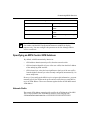
Mapping an MPS to a LAN Emulation Client
You must map an MPS to any LEC service likely to send and receive MPOA
resolution requests and replies over the ATM network. You can map one MPS to
one or more LEC services configured on the same ATM slot and connector.
2-8
309249-14.00 Rev 00
Starting MPOA and NHRP Services
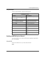
Using the BCC
To map an MPS to an LEC service, navigate to that LEC service and enter:
mpoa-server mps-name <mps-name>
For example, on a System 5000 router, the following BCC commands navigate to
the LEC service “newyork” and map the MPS named “eastcoast” to it:
stack# atm/5/3/1
atm/5/3/1# lec-service/newyork
lec-service/newyork# mpoa-server mps-name eastcoast
mpoa-server/newyork#
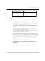
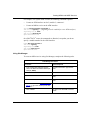
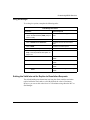
Figure 2-1 shows the configuration hierarchy and logical mapping between the
MPS and the LEC in this example.
stack
atm/5/31/1
signaling/5/3/1
(mapping object)
lec-service/newyork
mpoa-server/newyork
mps-to-lec-service
mapping
mpoa-service/5/3/1
mps/eastcoast
BCC0031A
Figure 2-1.
309249-14.00 Rev 00
Mapping an MPS to an LEC Service
2-9
Configuring MPOA and NHRP Services
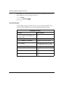
Using Site Manager
To map an MPOA server (MPS) to a LEC service, complete the following tasks:
Site Manager Procedure
You do this
System responds
1. In the Configuration Manager window,
click on an ATM link module interface (for
example, ATM1).
The Select Connection Type window
opens.
2. Click on ATM.
The Edit ATM Connector window opens.
3. Click on MPOA Server Attributes.
The MPOA Service Record window
opens.
4. Click on MPS.
The MPS List window opens.
5. Click on Mapping.
The LEC (to) MPS Mapping List window
opens.
6. Click on any LEC that you want to map to
the MPS.
7. Click on Mapping.
Site Manager maps the LEC to the MPS.
8. Repeat steps 8 and 9 to map any
additional LECs.
2-10
9. Click on Done.
You return to the MPS List window.
10. Click on Done.
You return to the MPOA Service Record
window.
11. Click on Done.
You return to the Edit ATM Connector
window.
12. Click on Done.
You return to the Select Connection Type
window.
13. Click on Done.
You return to the Configuration Manager
window.
309249-14.00 Rev 00
Starting MPOA and NHRP Services
Starting NHRP on an ATM PVC Service
To allow normally routed traffic to flow through an ATM PVC service and
between MPSs, enable IP plus an optional routing protocol (RIP or OSPF) on that
IP interface. (Configure RIP or OSPF if no routed paths exist between MPSs in
your ATM network).
To allow NHRP address resolution requests and replies to flow through the same
ATM PVC service and between MPSs, you must enable NHRP on that service.
You can use either the BCC or Site Manager to add IP, RIP or OSPF, and NHRP
to an ATM PVC service.
Using the BCC
To add IP, RIP or OSPF, and NHRP to an existing ATM PVC service:
1.
Navigate to the appropriate pvc-service prompt and enter:
nhrp
2.
Navigate back to the pvc-service prompt, and enter:
ip address <IP_address> mask <subnet_mask>
3.
At the resulting IP interface prompt, add a routing protocol (RIP or
OSPF):
rip
For example, on a System 5000 router, the following BCC commands navigate to
the pvc-service named “phoenix” and add NHRP, IP, and RIP:
stack# atm/5/3/1
atm/5/3/1# pvc-service servicename phoenix
pvc-service/phoenix# nhrp
nhrp/phoenix# back
ip/1.2.3.6/255.0.0.0# rip
rip/1.2.3.6#
When you add NHRP to any ATM PVC service, the BCC automatically creates
the global NHRP object at root level if you have not already done so.
309249-14.00 Rev 00
2-11
Configuring MPOA and NHRP Services
Using Site Manager
To add NHRP to an existing ATM interface, complete the following tasks:
Site Manager Procedure
You do this
System responds
1. In the Configuration Manager window,
click on the ATM interface (ATM1) on
which you want to add NHRP.
The Select Connection Type window
opens.
2. Click on ATM.
The Edit ATM Connector window opens.
3. Click on Service Attributes.
The ATM Service Records List window
opens.
4. Click on the PVC service record to which
you want to add NHRP.
5. Click on the Protocols menu in the upper
left corner of the window.
6. Choose Add/Delete.
The Select Protocols window opens.
7. Select IP, RIP, and NHRP.
8. Click on OK.
The IP Configuration window opens.
9. Set the following parameters:
• IP Address
• Subnet Mask
• Transmit Bcast Address
Click on Help or see Configuring IP, ARP,
RIP, and OSPF Services for parameter
descriptions.
10. Click on OK.
The NHRP Network Configuration (NHRP
global parameters) window opens if
NHRP has not been configured on any
interface.
(continued)
2-12
309249-14.00 Rev 00
Starting MPOA and NHRP Services
Site Manager Procedure (continued)
You do this
System responds
11. Use default values for the following
parameters:
• NHRP Request Path
• Client Enable
• Client Reg Interval
• Client Hold Time
• Client Request Timeout
• Client Request Retry
• Client Max Pending Request Entries
• Server Enable
• Server Forward Enable
• Server Max Next Hop Entries
• Server Max Pending Request
Entries
Click on Help or see the parameter
descriptions beginning on page A-14.
12. Click on OK.
You return to the ATM Service Records
List window which displays a summary of
the NHRP record that you configured.
13. Click on Done.
You return to the Edit ATM Connector
window.
14. Click on Done.
You return to the Select Connection Type
window.
15. Click on Done.
You return to the Configuration Manager
window.
309249-14.00 Rev 00
2-13
Configuring MPOA and NHRP Services
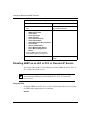
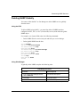
Starting NHRP on an ATM Classical IP (RFC 1577 SVC) Service
To allow normally routed traffic to flow through an ATM SVC (Classical IP)
service and between MPSs, enable IP plus an optional routing protocol on that IP
interface. (Configure RIP or OSPF if no routed path exists between MPSs in your
ATM network).
To allow NHRP address resolution requests and replies to flow through the same
ATM Classical IP (SVC) service and between MPSs, you must enable NHRP on
that service.
You can use either the BCC or Site Manager to add IP, RIP or OSPF, and NHRP
to the appropriate ATM Classical IP (SVC) service.
When configuring an RFC 1577 SVC connection between a pair of MPSs, keep
the following in mind:
•
The SVCs must use LLC/SNAP encapsulation (you cannot use NLPID or
NULL encapsulation on the SVC).
•
You must configure the SVC with IP and NHRP.
•
To avoid manually configuring adjacent hosts for each MPS, you may want to
configure the SVC to run RIP.
•
Set the client mode for the SVC to client on one MPS and server on the other
MPS.
For instructions on configuring an SVC service record with LLC/SNAP
encapsulation, see Configuring ATM Services.
Using the BCC
To add IP, RIP or OSPF, and NHRP to an existing ATM Classical IP (RFC 1577
SVC) service:
1.
Navigate to the desired classical-ip-service prompt and enter:
nhrp
2.
Navigate back to the classical-ip-service prompt, and enter:
ip address <IP_address> mask <subnet_mask>
2-14
309249-14.00 Rev 00
Starting MPOA and NHRP Services
3.
At the resulting IP interface prompt, add the desired routing protocol
(RIP or OSPF):
rip
For example, on a System 5000 router, the following BCC commands navigate to
the classical-ip-service named “baltimore” and add IP, RIP, and NHRP to that
service:
stack# atm/5/3/1
atm/5/3/1# classical-ip-service servicename baltimore
classical-ip-service/baltimore# nhrp
nhrp/baltimore# back
ip/1.2.3.6/255.0.0.0# rip
rip/1.2.3.6#
When you add NHRP to any ATM Classical IP service, the BCC automatically
creates the global NHRP object at root level if you have not already done so.
Using Site Manager
After you create an ATM SVC service record, the Add Protocols window opens.
To add IP, NHRP, and RIP to an SVC service record, complete the following tasks:
Site Manager Procedure
You do this
System responds
1. Click on IP.
A check mark appears in the IP box.
2. Click on RIP.
A check mark appears in the RIP box
3. Click on NHRP.
A check mark appears in the NHRP box.
4. Click on OK.
The IP Configuration window opens.
5. Set the following parameters:
• IP Address
• Subnet Mask
• Transmit Bcast Address
Click on Help or see Configuring IP, ARP,
RIP, and OSPF Services for parameter
descriptions.
6. Click on OK.
The ATM ARP Configuration window
opens.
(continued)
309249-14.00 Rev 00
2-15
Configuring MPOA and NHRP Services
Site Manager Procedure (continued)
You do this
System responds
7. Set the following parameters:
• ATM ARP Mode
• ARP Server ATM Address Network
Prefix
• ARP Server ATM Address User Part
Click on Help or see the parameter
descriptions in Configuring ATM Services.
8. Click on OK.
The NHRP Network Configuration
window opens.
9. Click on OK.
You return to the ATM Service Records
List window.
10. Click on Done.
You return to the Edit ATM Connector
window.
11. Click on Done.
You return to the Select Connection Type
window.
12. Click on Done.
You return to the Configuration Manager
window.
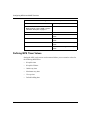
Where to Go Next
Use the following table to determine where to go next.
2-16
If you want to
Go to
Obtain an overview of MPOA and NHRP operation.
Chapter 1
Change default settings for MPOA server
parameters.
Chapter 3
Change default settings for NHRP client or server
parameters.
Chapter 4
Obtain information about Site Manager parameters.
Appendix A
Obtain information about BCC parameters
Appendix B
Monitor ATM using the BCC show commands.
Appendix C
Review an example MPOA and NHRP configuration
process.
Appendix D
Review the BCC configuration tree for MPOA and
NHRP services.
Appendix E
309249-14.00 Rev 00
Chapter 3
Customizing MPOA Services
Bay Networks supports Multi-Protocol over ATM (MPOA) server configuration.
MPOA is the ATM Forum standard that specifies a way to efficiently transport
intersubnet, unicast data in a LANE environment. For general information about
the Bay Networks implementation of MPOA, see “Multi-Protocol over ATM” on
page 1-2.
This chapter describes how to customize an MPOA server configuration and
includes the following information:
Topic
Page
Disabling and Reenabling an MPOA Service
3-2
Setting the MPS Address Generating Mode
3-3
Specifying an MPS Control ATM Address
3-5
Disabling and Reenabling MPOA Servers
3-8
Specifying the MPS Configuration Mode
3-10
Specifying a LECS ATM Address
3-11
Configuring a Unique Selector Byte for an MPS Address
3-14
Defining MPS Timer Values
3-16
Defining MPS Cache Values
3-25
Deleting MPOA Servers
3-28
Deleting an MPOA Service Record
3-29
Where to Go Next
3-31
You must create an MPOA service record before you can customize an MPS. For
information about creating an MPOA service record and starting the MPOA
server, see “Starting the MPOA Server” on page 2-2.
305861-A Rev 00
3-1
Configuring MPOA and NHRP Services
Disabling and Reenabling an MPOA Service
The MPOA service on an ATM interface is normally enabled, which allows
MPOA servers (MPSs) configured on that service to operate normally. If you need
to functionally disable all MPSs configured on a service simultaneously, disable
the underlying MPOA service. You can do this using either the BCC or Site
Manager.
Using the BCC
To disable an MPOA Service, navigate to that service and enter:
state disabled
or:
To reenable an MPOA Service, navigate to that service and enter:
state enabled
For example, on a System 5000 router, the following commands:
•
Navigate from root (stack#) level to the MPOA service on existing interface
atm/5/3/1. (Assume that ATM signalling was enabled earlier with atm/5/3/1.)
•
Disable the MPOA service, functionally disabling all MPSs configured on
atm/5/3/1.
•
Reenable the same MPOA service, functionally reenabling all MPSs
configured on atm/5/3/1.
stack# atm slot 5 module 3 connector 1
atm/5/3/1# mpoa-service
mpoa-service/5/3/1# state disabled
mpoa-service/5/3/1# state enabled
mpoa-service/5/3/1#
3-2
305861-A Rev 00
Customizing MPOA Services
Using Site Manager
To disable or reenable the MPOA service record, complete the following tasks:
Site Manager Procedure
You do this
System responds
1. In the Configuration Manager window,
The Select Connection Type window
click on the ATM interface (ATM1) that you opens.
want to modify.
2. Click on ATM.
The Edit ATM Connector window opens.
3. Click on MPOA Server Attributes.
The MPOA Service Record window
opens.
4. Set the Enable/Disable parameter. Click
on Help or see the parameter description
on page A-3.
5. Click on Done.
You return to the Edit ATM Connector
window.
6. Click on Done.
You return to the Select Connection Type
window.
7. Click on Done.
You return to the Configuration Manager
window.
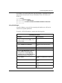
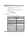
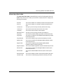
Setting the MPS Address Generating Mode
By default, a newly created MPS automatically uses the 13-byte ATM address
domain that it receives from the network switch. In this default mode (automatic
address generation), the MPS also uses the MAC address of the underlying ATM
interface as the basis for the 7-byte user suffix of the MPS address.
You can alternatively configure a new MPS with an ATM address that you provide
in the MPOA service record. Whether derived automatically by MPOA or
manually from the MPOA service record, the address assigned to each MPS is its
control ATM address.
You can use the BCC or Site Manager to change the MPS address generation
mode from automatic to manual.
305861-A Rev 00
3-3
Configuring MPOA and NHRP Services
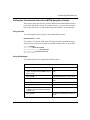
Using the BCC
To set the MPS address generating mode, navigate to the appropriate ATM
mpoa-service and enter the following command:
autogenerate { enabled
|
disabled }
With this mode enabled, the MPS automatically generates an ATM address based
on information it receives from an LECS. If you disable this mode, the MPS uses
an ATM address based on the value you configured for the network-prefix and
user-suffix parameters of the MPOA service record. (If you disable address
autogeneration, be sure to configure values for network-prefix and user-suffix.)
For example, on a System 5000 router, the following commands:
•
Navigate to the mpoa-service on ATM interface atm/5/3/1 on a System 5000
router.
•
Disable ATM address autogeneration.
stack# atm/5/3/1
atm/5/3/1# mpoa-service/5/3/1
mpoa-service/5/3/1# autogenerate disabled
Using Site Manager
To set the MPS address generating mode, complete the following tasks:
Site Manager Procedure
You do this
System responds
1. In the Configuration Manager window,
The Select Connection Type window
click on the ATM interface (ATM1) that you opens.
want to modify.
2. Click on ATM.
The Edit ATM Connector window opens.
3. Click on MPOA Server Attributes.
The MPOA Service Record window
opens.
4. Set the MPS Address Generate Mode
parameter. Click on Help or see the
parameter description on page A-3.
(continued)
3-4
305861-A Rev 00
Customizing MPOA Services
Site Manager Procedure (continued)
You do this
System responds
5. Click on Done.
You return to the Edit ATM Connector
window.
6. Click on Done.
You return to the Select Connection Type
window.
7. Click on Done.
You return to the Configuration Manager
window.
Note: The MPS Address Generate Mode parameter also appears in the MPS
List window and the MPS Configuration Parameters window for display
purposes only. You must configure this parameter at the Site Manager MPOA
service record level.
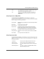
Specifying an MPS Control ATM Address
By default, an MPS automatically inherits its:
•
ATM address domain (network prefix) from the network switch
•
ATM end-station identifier (6 bytes of the user suffix) from the MAC address
of the underlying ATM interface
•
ATM selector byte value (the least-significant or last byte of the user suffix)
from the highest selector byte value currently configured, incremented by 1 to
ensure uniqueness.
However, if you configure the MPOA service to ignore this information, you must
manually specify the ATM network prefix and user suffix that you want MPS to
use in its ATM address. These two elements together define the full MPS control
ATM address.
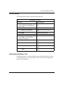
Network Prefix
The control ATM address network prefix specifies the ATM domain of the MPS.
This 13-byte portion of the ATM address can have values ranging from
XX000000000000000000000000 to XXFFFFFFFFFFFFFFFFFFFFFFFF.
305861-A Rev 00
3-5
Configuring MPOA and NHRP Services
For user-configured network prefix values, the XX byte must contain 39, 45, or 47.
These values define the authority and format identifier (AFI). The AFI byte
identifies the group responsible for allocating the prefix and the format the prefix
uses. For more information about the AFI byte, refer to the ATM Forum UNI
specification.
Entering an ATM address network prefix is optional. If you do not enter a network
prefix in the specified range, the MPS accepts the first prefix value that it receives
from the local switch.
Note: Each MPS obtains its ATM network prefix from the network prefix
assigned to the MPOA service record. This means that all MPSs that you add
to an MPOA service record will have the same ATM network prefix.
User Suffix
The control ATM address user part consists of a 6-byte end-station identifier and a
1-byte selector field. This 7-byte portion of the ATM address can have values
ranging from 00000000000000 to FEFFFFFFFFFFFF.
With ATM address generation in manual mode (autogeneration disabled), you can
use the BCC or Site Manager to manually configure a network prefix and user
suffix for the control ATM address.
Using the BCC
To configure a value for the network prefix in the MPS control ATM address:
1.
Navigate to the appropriate mpoa-service prompt and ensure that the
autogenerate parameter has a value of disabled, for example:
mpoa-service/5/3/1# autogenerate
autogenerate disabled
2.
Configure a value for the network-prefix portion of the MPS control
ATM address by entering:
network-prefix <13_byte_octet_string>
3.
Configure a value for the user-suffix portion of the MPS control ATM
address by entering:
user-suffix <7_byte_octet_string>
3-6
305861-A Rev 00
Customizing MPOA Services
For example, on a System 5000 router, the following commands:
•
Navigate to the MPOA service on atm/5/3/1.
•
Check to ensure that ATM address generation is in manual mode.
•
Set a control ATM address network prefix and user suffix.
mpoa-service/5/3/1# autogenerate
autogenerate disabled
mpoa-service/5/3/1# network-prefix 39aabbccddeeffaabbccddeeff
mpoa-service/5/3/1# user-suffix abcdefabcdefab
mpoa-service/5/3/1#
Using Site Manager
This procedure assumes that the MPS Address Generate Mode parameter in the
MPOA Server Attributes window has been set to manual.
Now specify the control ATM address network prefix by completing the following
tasks:
Site Manager Procedure
You do this
System responds
1. In the Configuration Manager window,
The Select Connection Type window
click on the ATM interface (ATM1) that you opens.
want to modify.
2. Click on ATM.
The Edit ATM Connector window opens.
3. Click on MPOA Server Attributes.
The MPOA Service Record window
opens.
4. Set the Ctrl ATM Addr Network Prefix
and Ctrl ATM Addr User Part parameters.
Click on Help or see the parameter
descriptions on page A-4.
305861-A Rev 00
5. Click on Done.
You return to the Edit ATM Connector
window.
6. Click on Done.
You return to the Select Connection Type
window.
7. Click on Done.
You return to the Configuration Manager
window.
3-7
Configuring MPOA and NHRP Services
Disabling and Reenabling MPOA Servers
When you finish mapping an MPS to one or more LECs on the same slot, you can
use either the BCC or Site Manager to disable and subsequently reenable that
MPS for troubleshooting or other reasons.
Using the BCC
To disable a single MPS, navigate to the MPS you want to disable and enter:
state disabled
To reenable a disabled MPS, navigate to the MPS that you want to reenable and
enter:
state enabled
For example, on a System 5000 router, the following commands navigate to,
disable, and then reenable the MPS on mpoa-service/5/3/1:
Disabling:
stack# atm/5/3/1
atm/5/3/1# mpoa-service/5/3/1
mpoa-service/5/3/1# mps/newyork
mps/newyork# state disabled
Reenabling:
stack# atm/5/3/1
atm/5/3/1# mpoa-service/5/3/1
mpoa-service/5/3/1# mps/newyork
mps/newyork# state enabled
To disable or reenable multiple MPSs simultaneously, navigate to the MPOA
service on which the MPSs exist and enter:
disable mps/<mpsname> ...
or:
enable mps/<mpsname> ...
3-8
305861-A Rev 00
Customizing MPOA Services
For example, on a System 5000 router, the following BCC commands navigate to
and disable two MPSs on mpoa-service/5/3/1:
stack# atm/5/3/1
atm/5/3/1# mpoa-service/5/3/1
mpoa-service/5/3/1# disable mps/newyork mps/chicago
mpoa-service/5/3/1#
Using Site Manager
To disable or reenable MPSs already mapped to LEC services, complete the
following tasks:
Site Manager Procedure
You do this
System responds
1. In the Configuration Manager window,
The Select Connection Type window
click on the ATM interface (ATM1) that you opens.
want to modify.
2. Click on ATM.
The Edit ATM Connector window opens.
3. Click on MPOA Server Attributes.
The MPOA Service Record window
opens.
4. Click on MPS.
The MPS List window opens.
5. Click on the MPS that you want to modify.
6. Set the Enable/Disable parameter. Click
on Help or see the parameter description
on page A-7.
305861-A Rev 00
7. Click on Done.
You return to the MPOA Service Record
window.
8. Click on Done.
You return to the Edit ATM Connector
window.
9. Click on Done.
You return to the Select Connection Type
window.
10. Click on Done.
You return to the Configuration Manager
window.
3-9
Configuring MPOA and NHRP Services
Specifying the MPS Configuration Mode
The MPS configuration mode determines whether the MPS obtains configuration
parameter values (for example, timer settings) automatically from the LAN
emulation configuration server (LECS) or from the manual settings that you
provide. Once you determine the source from which the router must obtain MPS
configuration parameter values, set the MPS configuration mode to either
automatic or manual, accordingly.
In manual mode, you either accept the router’s MPS default timer values or
change those values to suit your requirements (see “Defining MPS Timer Values”
on page 3-16).
You can specify the MPS configuration mode using either the BCC or Site
Manager.
Using the BCC
To specify the configuration mode used by each MPS, navigate to the appropriate
MPS and enter:
config-mode {automatic | manual}
For example, on a System 5000 router, the following commands navigate to
mps/newyork on interface atm/5/3/1 and change the MPS configuration mode
from its default value (automatic) to its alternate value (manual):
stack# atm/5/3/1
atm/5/3/1# mpoa-service/5/3/1
mpoa-service/5/3/1# mps/newyork
mps/newyork# config-mode manual
3-10
305861-A Rev 00
Customizing MPOA Services
Using Site Manager
To change the MPS configuration mode, complete the following tasks:
Site Manager Procedure
You do this
System responds
1. In the Configuration Manager window,
The Select Connection Type window
click on the ATM interface (ATM1) that you opens.
want to modify.
2. Click on ATM.
The Edit ATM Connector window opens.
3. Click on MPOA Server Attributes.
The MPOA Service Record window
opens.
4. Click on MPS.
The MPS List window opens.
5. Click on the MPS that you want to modify.
6. Set the MPS Config Mode parameter.
Click on Help or see the parameter
description on page A-9.
7. Click on Done.
You return to the MPOA Service Record
window.
8. Click on Done.
You return to the Edit ATM Connector
window.
9. Click on Done.
You return to the Select Connection Type
window.
10. Click on Done.
You return to the Configuration Manager
window.
Specifying a LECS ATM Address
You can use either the BCC or Site Manager to specify which LECS you want the
MPS to use when obtaining parameter information. Entering this ATM address is
optional; if you do not enter an address, the MPS automatically uses the
well-known LECS ATM address to open a configuration VCC.
305861-A Rev 00
3-11
Configuring MPOA and NHRP Services
To manually specify the LECS ATM address for an MPS, you must set the
following address elements:
•
LECS ATM address network prefix
•
LECS ATM address user suffix
These two elements together define the full ATM address of the LECS.
Note: The combined network prefix and user suffix must match the address of
the LECS for the network.
Network Prefix
The LECS ATM address network prefix specifies the ATM domain of the MPS.
This 13-byte portion of the ATM address can range from
XX000000000000000000000000 to XXFFFFFFFFFFFFFFFFFFFFFFFF.
The XX byte typically contains 39, 45, or 47. These values define the authority and
format identifier (AFI). The AFI byte identifies the group responsible for
allocating the prefix and the format that the prefix uses. For more information
about the AFI byte, refer to the ATM Forum UNI specification.
User Suffix
The LEC ATM address user suffix typically contains a 6-byte end-station
identifier and a 1-byte selector field. This 7-byte portion of the ATM address can
range from 00000000000000 to FEFFFFFFFFFFFF.
Using the BCC
Using the BCC, you can specify both parts of the address as the value for one
parameter (lecs-address).
To specify a LECS ATM address for the MPS, navigate to the appropriate MPS
prompt and enter:
lecs-address <20_byte_octet_string>
3-12
305861-A Rev 00
Customizing MPOA Services
For example, on a System 5000 router, the following BCC commands navigate to
mps/eastcoast and specify the 20-byte ATM address of the LECS that server
should use.
stack# atm/5/3/1
atm/5/3/1# mpoa-service/5/3/1
mpoa-service/5/3/1# mps/eastcoast
mps/eastcoast# lecs-address 45aabbccddeeff9988776655443311aabbccddff
mps/eastcoast#
Using Site Manager
Using Site Manager, you specify the network prefix and the user suffix as the
values for two separate parameters.
To specify a LECS ATM address, complete the following tasks:
Site Manager Procedure
You do this
System responds
1. In the Configuration Manager window,
The Select Connection Type window
click on the ATM interface (ATM1) that you opens.
want to modify.
2. Click on ATM.
The Edit ATM Connector window opens.
3. Click on MPOA Server Attributes.
The MPOA Service Record window
opens.
4. Click on MPS.
The MPS List window opens.
5. Click on the MPS that you want to modify.
6. Set the LECS ATM Address parameter.
Click on Help or see the parameter
descriptions for the LECS ATM Addr
Network Prefix and LECS ATM Address
User Part parameters on page A-6.
305861-A Rev 00
7. Click on Done.
You return to the MPOA Service Record
window.
8. Click on Done.
You return to the Edit ATM Connector
window.
9. Click on Done.
You return to the Select Connection Type
window.
10. Click on Done.
You return to the Configuration Manager
window.
3-13
Configuring MPOA and NHRP Services
Note: When you initially add a LECS ATM address, you do so by configuring
a separate ATM network prefix and ATM user part. However, when you
modify an existing LECS ATM address, you need only change one parameter
that contains both the ATM network prefix and the ATM user part suffix
portion of the LECS address.
Configuring a Unique Selector Byte for an MPS Address
If you disable ATM address autogeneration, a newly created MPS uses the control
ATM address user suffix that you configured in the MPOA service record.
However, to ensure uniqueness among all ATM addresses used on the router, you
must additionally specify a unique value for the 1-byte selector field of the MPS
ATM address.
You can determine the user suffix values for MPSs currently configured on the
router by entering the following command at any BCC prompt:
show mpoa server
Based on the output of this command, assign to each new MPS a selector byte
value that is unique among selector byte values used for any other ATM addresses
configured on the router. For example, if the highest user suffix used by any
MPOA servers configured on the router is 0011223344556677 (selector byte
value = 77), you could assign the next available user suffix value,
0011223344556678 (selector byte value = 78).
You can set a unique selector byte value using either the BCC or Site Manager.
3-14
305861-A Rev 00
Customizing MPOA Services
Using the BCC
To customize the selector byte of the control ATM address value inherited by the
MPS, navigate to the desired MPS and enter:
control-atm-address <20_byte_octet_string>
For example, on a System 5000 router, the following commands:
•
Navigate to the MPOA service on atm/5/3/1.
•
Navigate to mps/newyork and reenter the full control ATM address (from the
MPOA service level) as the value for the MPS control-atm-address parameter,
but with a unique value for the selector byte.
stack# atm/5/3/1
atm/5/3/1# mpoa-service/5/3/1
mpoa-service/5/3/1# mps/newyork
mps/newyork# control-atm-address 45112233445566778899AABBCC11223344556678
mps/newyork#
Using Site Manager
This procedure assumes that the MPS Address Generate Mode parameter in the
MPOA Server Attributes window has been set to manual.
To specify the MPS control ATM address selector byte, complete the following
tasks:
Site Manager Procedure
You do this
System responds
1. In the Configuration Manager window,
The Select Connection Type window
click on the ATM interface (ATM1) that you opens.
want to modify.
2. Click on ATM.
The Edit ATM Connector window opens.
3. Click on MPOA Server Attributes.
The MPOA Service Record window
opens.
4. Click on MPS.
The MPS List window opens.
5. Click on Add.
The MPS Configuration Parameters
window opens.
(continued)
305861-A Rev 00
3-15
Configuring MPOA and NHRP Services
Site Manager Procedure (continued)
You do this
System responds
6. Set the MPS Ctrl ATM Address Selector
Byte parameter. Click on Help or see the
parameter description on page A-7.
7. Click on Done.
You return to the MPS List window.
8. Click on Done.
You return to the MPOA Service Record
window.
9. Click on Done.
You return to the Edit ATM Connector
window.
10. Click on Done.
You return to the Select Connection Type
window.
11. Click on Done.
You return to the Configuration Manager
window.
Defining MPS Timer Values
Setting the MPS configuration mode to manual allows you to customize values for
the following MPS timers:
3-16
•
Keepalive time
•
Keepalive lifetime
•
Initial retry time
•
Maximum retry time
•
Give up time
•
Default holding time
305861-A Rev 00
Customizing MPOA Services
Setting the Transmission Interval for MPOA Keepalive Packets
The keepalive time specifies how often the MPS must transmit MPOA keepalive
packets. By default, the value is 10 seconds. However, you can set the keepalive
time to any value from 1 to 300 seconds using either the BCC or Site Manager.
Using the BCC
To set the keepalive time, navigate to the desired MPS and enter:
keep-alive-time <1-300>
For example, on a System 5000 router, the following BCC commands navigate
from root level to mps/eastcoast and set the MPS keepalive time to 100 seconds:
stack# atm/5/3/1
atm/5/3/1# mpoa-service/5/3/1
mpoa-service/5/3/1# mps/eastcoast
mps/eastcoast# keep-alive-time 100
mps/eastcoast#
Using Site Manager
To set the keepalive time, complete the following tasks:
Site Manager Procedure
You do this
System responds
1. In the Configuration Manager window,
The Select Connection Type window
click on the ATM interface (ATM1) that you opens.
want to modify.
2. Click on ATM.
The Edit ATM Connector window opens.
3. Click on MPOA Server Attributes.
The MPOA Service Record window
opens.
4. Click on MPS.
The MPS List window opens.
5. Click on the MPS that you want to modify.
6. Set the Keep Alive Time parameter. Click
on Help or see the parameter description
on page A-12.
7. Click on Done.
You return to the MPOA Service Record
window.
(continued)
305861-A Rev 00
3-17
Configuring MPOA and NHRP Services
Site Manager Procedure (continued)
You do this
System responds
8. Click on Done.
You return to the Edit ATM Connector
window.
9. Click on Done.
You return to the Select Connection Type
window.
10. Click on Done.
You return to the Configuration Manager
window.
Setting the Valid Lifetime for Keepalive Packets
The keepalive lifetime is the length of time that an MPOA client (MPC) considers
valid a keepalive packet sent by its MPS. (The packet contains its keepalive value.)
By default, the keepalive lifetime is 35 seconds. However, you can set this value
from 3 to 1000 seconds using either the BCC or Site Manager.
Using the BCC
To set the keepalive lifetime, navigate to the desired MPS and enter:
keep-alive-lifetime <3-1000>
For example, on a System 5000 router, the following BCC commands navigate
from root level to mps/eastcoast and set the MPS keepalive lifetime to 500
seconds:
stack# atm/5/3/1
atm/5/3/1# mpoa-service/5/3/1
mpoa-service/5/3/1# mps/eastcoast
mps/eastcoast# keep-alive-lifetime 500
mps/eastcoast#
3-18
305861-A Rev 00
Customizing MPOA Services
Using Site Manager
To set the keepalive lifetime, complete the following tasks:
Site Manager Procedure
You do this
System responds
1. In the Configuration Manager window,
The Select Connection Type window
click on the ATM interface (ATM1) that you opens.
want to modify.
2. Click on ATM.
The Edit ATM Connector window opens.
3. Click on MPOA Server Attributes.
The MPOA Service Record window
opens.
4. Click on MPS.
The MPS List window opens.
5. Click on the MPS that you want to modify.
6. Set the Keep Alive Life Time parameter.
Click on Help or see the parameter
description on page A-12.
7. Click on Done.
You return to the MPOA Service Record
window.
8. Click on Done.
You return to the Edit ATM Connector
window.
9. Click on Done.
You return to the Select Connection Type
window.
10. Click on Done.
You return to the Configuration Manager
window.
Setting the Initial Retry Time
The initial retry time is used by the MPOA retry mechanism. By default, the value
is 5 seconds. However, you can set this value from 1 to 300 seconds using either
the BCC or Site Manager.
305861-A Rev 00
3-19
Configuring MPOA and NHRP Services
Using the BCC
To set the initial retry time, navigate to the appropriate MPS and enter:
initial-retry-time <1-300>
For example, on a System 5000 router, the following commands navigate from
root level to mps/eastcoast and set the MPS initial retry time to 50 seconds:
stack# atm/5/3/1
atm/5/3/1# mpoa-service/5/3/1
mpoa-service/5/3/1# mps/eastcoast
mps/eastcoast# initial-retry-time 50
mps/eastcoast#
Using Site Manager
To set the initial retry time, complete the following tasks:
Site Manager Procedure
You do this
System responds
1. In the Configuration Manager window,
The Select Connection Type window
click on the ATM interface (ATM1) that you opens.
want to modify.
2. Click on ATM.
The Edit ATM Connector window opens.
3. Click on MPOA Server Attributes.
The MPOA Service Record window
opens.
4. Click on MPS.
The MPS List window opens.
5. Click on the MPS that you want to modify.
6. Set the Initial Retry Time parameter.
Click on Help or see the parameter
description on page A-11.
3-20
7. Click on Done.
You return to the MPOA Service Record
window.
8. Click on Done.
You return to the Edit ATM Connector
window.
9. Click on Done.
You return to the Select Connection Type
window.
10. Click on Done.
You return to the Configuration Manager
window.
305861-A Rev 00
Customizing MPOA Services
Setting the Maximum Retry Time
The maximum retry time is used by the MPOA retry mechanism. By default, the
value is 40 seconds. However, you can set this value from 10 to 300 seconds using
either the BCC or Site Manager.
Using the BCC
To set the maximum retry time, navigate to the desired MPS and enter:
retry-time-maximum <10-300>
For example, on a System 5000 router, the following commands navigate from
root level to mps/eastcoast and set the MPS maximum retry time to 200 seconds:
stack# atm/5/3/1
atm/5/3/1# mpoa-service/5/3/1
mpoa-service/5/3/1# mps/eastcoast
mps/eastcoast# retry-time-maximum 200
mps/eastcoast#
Using Site Manager
To set the maximum retry time, complete the following tasks:
Site Manager Procedure
You do this
System responds
1. In the Configuration Manager window,
The Select Connection Type window
click on the ATM interface (ATM1) that you opens.
want to modify.
2. Click on ATM.
The Edit ATM Connector window opens.
3. Click on MPOA Server Attributes.
The MPOA Service Record window
opens.
4. Click on MPS.
The MPS List window opens.
5. Click on the MPS that you want to modify.
6. Set the Maximum Retry Time parameter.
Click on Help or see the parameter
description on page A-13.
7. Click on Done.
You return to the MPOA Service Record
window.
(continued)
305861-A Rev 00
3-21
Configuring MPOA and NHRP Services
Site Manager Procedure (continued)
You do this
System responds
8. Click on Done.
You return to the Edit ATM Connector
window.
9. Click on Done.
You return to the Select Connection Type
window.
10. Click on Done.
You return to the Configuration Manager
window.
Setting the Time to Wait for Responses to Resolution Requests
The give-up time is the minimum amount of time that the MPS must wait before
giving up on a pending resolution request. By default, the value is 40 seconds.
However, you can set this value from 5 to 300 seconds using either the BCC or
Site Manager.
Using the BCC
To set the give-up time, navigate to the desired MPS and enter:
give-up-time <5-300>
For example, on a System 5000 router, the following BCC commands navigate
from root level to mps/eastcoast and set the MPS give-up time to 175 seconds:
stack# atm/5/3/1
atm/5/3/1# mpoa-service/5/3/1
mpoa-service/5/3/1# mps/eastcoast
mps/eastcoast# give-up-time 175
mps/eastcoast#
3-22
305861-A Rev 00
Customizing MPOA Services
Using Site Manager
To set the give-up time, complete the following tasks:
Site Manager Procedure
You do this
System responds
1. In the Configuration Manager window,
The Select Connection Type window
click on the ATM interface (ATM1) that you opens.
want to modify.
2. Click on ATM.
The Edit ATM Connector window opens.
3. Click on MPOA Server Attributes.
The MPOA Service Record window
opens.
4. Click on MPS.
The MPS List window opens.
5. Click on the MPS that you want to modify.
6. Set the Give Up Time parameter. Click on
Help or see the parameter description on
page A-10.
7. Click on Done.
You return to the MPOA Service Record
window.
8. Click on Done.
You return to the Edit ATM Connector
window.
9. Click on Done.
You return to the Select Connection Type
window.
10. Click on Done.
You return to the Configuration Manager
window.
Setting the Valid Interval for Replies to Resolution Requests
The default holding time determines how long the client considers resolution
replies held in the local cache as valid. By default, the value is 20 minutes.
However, you can set this value from 1 to 120 minutes using either the BCC or
Site Manager.
305861-A Rev 00
3-23
Configuring MPOA and NHRP Services
Using the BCC
To set the default holding time, navigate to the desired MPS and enter:
default-holding-time <1-120>
For example, on a System 5000 router, the following BCC commands navigate
from root level to mps/eastcoast and set the MPS default holding time to
90 minutes:
stack# atm/5/3/1
atm/5/3/1# mpoa-service/5/3/1
mpoa-service/5/3/1# mps/eastcoast
mps/eastcoast# default-holding-time 90
mps/eastcoast#
Using Site Manager
To set the default holding time, complete the following tasks:
Site Manager Procedure
You do this
System responds
1. In the Configuration Manager window,
The Select Connection Type window
click on the ATM interface (ATM1) that you opens.
want to modify.
2. Click on ATM.
The Edit ATM Connector window opens.
3. Click on MPOA Server Attributes.
The MPOA Service Record window
opens.
4. Click on MPS.
The MPS List window opens.
5. Click on the MPS that you want to modify.
6. Set the Default Holding Time parameter.
Click on Help or see the parameter
description on page A-10.
3-24
7. Click on Done.
You return to the MPOA Service Record
window.
8. Click on Done.
You return to the Edit ATM Connector
window.
9. Click on Done.
You return to the Select Connection Type
window.
10. Click on Done.
You return to the Configuration Manager
window.
305861-A Rev 00
Customizing MPOA Services
Defining MPS Cache Values
The MPS can contain cache information upon initialization and can accumulate
this information during its operation. Bay Networks provides control over this
cache information.
Caution: The values you set for cache parameters affect router memory
resources. Use caution when setting higher values.
Setting the Initial Cache Size
The initial cache size specifies the maximum number of cache units that the MPS
can keep upon initialization. By default, the MPS can have a maximum initial
cache size of 100 units. (Its actual initial size is typically zero.) You can use either
the BCC or Site Manager to set the maximum initial cache size to any value from
50 to 500 units.
Using the BCC
To set the initial cache size, navigate to the appropriate MPS and enter:
initial-cache-size <50-500>
For example, on a System 5000 router, the following BCC commands navigate
from root level to mps/eastcoast and set the MPS initial cache size to 150 units:
stack# atm/5/3/1
atm/5/3/1# mpoa-service/5/3/1
mpoa-service/5/3/1# mps/eastcoast
mps/eastcoast# initial-cache-size 150
mps/eastcoast#
305861-A Rev 00
3-25
Configuring MPOA and NHRP Services
Using Site Manager
To set the initial cache size, complete the following tasks:
Site Manager Procedure
You do this
System responds
1. In the Configuration Manager window,
The Select Connection Type window
click on the ATM interface (ATM1) that you opens.
want to modify.
2. Click on ATM.
The Edit ATM Connector window opens.
3. Click on MPOA Server Attributes.
The MPOA Service Record window
opens.
4. Click on MPS.
The MPS List window opens.
5. Click on the MPS that you want to modify.
6. Set the Initial Cache Size parameter.
Click on Help or see the parameter
description on page A-11.
7. Click on Done.
You return to the MPOA Service Record
window.
8. Click on Done.
You return to the Edit ATM Connector
window.
9. Click on Done.
You return to the Select Connection Type
window.
10. Click on Done.
You return to the Configuration Manager
window.
Setting the Maximum Cache Size
The maximum cache size specifies the maximum number of cache units that the
MPS can store at any time. By default, the MPS can have a maximum cache size
of 500 units. However, you can use either the BCC or Site Manager to set the
maximum cache size to any value from 100 to 2000 units.
3-26
305861-A Rev 00
Customizing MPOA Services
Using the BCC
To set the maximum cache size, navigate to the appropriate MPS and enter:
maximum-cache-size <100-2000>
For example, on a System 5000 router, the following BCC commands navigate
from root level to mps/eastcoast and set the MPS maximum cache size to 300
units:
stack# atm/5/3/1
atm/5/3/1# mpoa-service/5/3/1
mpoa-service/5/3/1# mps/eastcoast
mps/eastcoast# maximum-cache-size 300
mps/eastcoast#
Using Site Manager
To set the maximum cache size, complete the following tasks:
Site Manager Procedure
You do this
System responds
1. In the Configuration Manager window,
The Select Connection Type window
click on the ATM interface (ATM1) that you opens.
want to modify.
2. Click on ATM.
The Edit ATM Connector window opens.
3. Click on MPOA Server Attributes.
The MPOA Service Record window
opens.
4. Click on MPS.
The MPS List window opens.
5. Click on the MPS that you want to modify.
6. Set the Maximum Cache Size parameter.
Click on Help or see the parameter
description on page A-13.
7. Click on Done.
You return to the MPOA Service Record
window.
8. Click on Done.
You return to the Edit ATM Connector
window.
(continued)
305861-A Rev 00
3-27
Configuring MPOA and NHRP Services
Site Manager Procedure (continued)
You do this
System responds
9. Click on Done.
You return to the Select Connection Type
window.
10. Click on Done.
You return to the Configuration Manager
window.
Deleting MPOA Servers
You can use either the BCC or Site Manager to delete one or more MPSs from an
MPOA service record.
Using the BCC
To delete a single MPS, navigate to the MPS that you want to delete and enter:
delete
For example, on a System 5000 router, the following commands navigate to and
delete the MPS on mpoa-service/5/3/1:
stack# atm/5/3/1
atm/5/3/1# mpoa-service/5/3/1
mpoa-service/5/3/1# mps/newyork
mps/newyork# delete
mpoa-service/5/3/1#
If you want to delete multiple MPSs simultaneously, navigate to the MPOA
service on which the MPSs exist, and enter:
delete mps/<mpsname> ...
For example, on a System 5000 router, the following commands navigate to and
delete two MPSs on mpoa-service/5/3/1:
stack# atm/5/3/1
atm/5/3/1# mpoa-service/5/3/1
mpoa-service/5/3/1# delete mps/newyork mps/chicago
mpoa-service/5/3/1#
3-28
305861-A Rev 00
Customizing MPOA Services
Using Site Manager
To delete an individual MPS, complete the following tasks:
Site Manager Procedure
You do this
System responds
1. In the Configuration Manager window,
The Select Connection Type window
click on the ATM interface (ATM1) that you opens.
want to modify.
2. Click on ATM.
The Edit ATM Connector window opens.
3. Click on MPOA Server Attributes.
The MPOA Service Record window
opens.
4. Click on MPS.
The MPS List window opens.
5. Click on the MPS that you want to delete.
6. Click on Delete.
Site Manager deletes the MPS.
7. Click on Done.
You return to the MPOA Service Record
window.
8. Click on Done.
You return to the Edit ATM Connector
window.
9. Click on Done.
You return to the Select Connection Type
window.
10. Click on Done.
You return to the Configuration Manager
window.
Deleting an MPOA Service Record
You can delete MPOA services from an ATM interface completely using either the
BCC or Site Manager.
Using the BCC
Navigate to the MPOA service you want to delete and enter:
delete
305861-A Rev 00
3-29
Configuring MPOA and NHRP Services
For example, on a System 5000 router, the following commands navigate to and
delete the MPOA service on interface atm/5/3/1:
stack# atm/5/3/1
atm/5/3/1# mpoa-service/5/3/1
mpoa-service/5/3/1# delete
atm/5/3/1#
Using Site Manager
To delete MPOA from the interface entirely, you must delete the MPOA service
record. To delete the MPOA service record, complete the following tasks:
Site Manager Procedure
You do this
System responds
1. In the Configuration Manager window,
The Select Connection Type window
click on the ATM interface (ATM1) that you opens.
want to modify.
3-30
2. Click on ATM.
The Edit ATM Connector window opens.
3. Click on MPOA Server Attributes.
The MPOA Service Record window
opens.
4. Click on Delete.
Site Manager asks whether you really
want to delete MPOA from this interface.
5. Click on Yes.
Site Manager deletes the service record.
6. Click on Done.
You return to the Edit ATM Connector
window.
7. Click on Done.
You return to the Select Connection Type
window.
8. Click on Done.
You return to the Configuration Manager
window.
305861-A Rev 00
Customizing MPOA Services
Where to Go Next
Use the following table to determine where to go next.
305861-A Rev 00
If you want to
Go to
Learn about ATM concepts.
Configuring ATM Services
Learn about MPOA and NHRP concepts.
Chapter 1
Change default settings for NHRP client or server
parameters.
Chapter 4
Obtain information about Site Manager MPOA and
NHRP parameters.
Appendix A
Obtain information about BCC MPOA and NHRP
parameters.
Appendix B
Monitor MPOA and NHRP using the BCC show
commands.
Appendix C
Review a BCC MPOA/NHRP example configuration
sequence.
Appendix D
Review the BCC MPOA/NHRP configuration tree.
Appendix E
3-31
Chapter 4
Customizing NHRP Services
This chapter includes the following information:
Accessing NHRP Client and Server Global Parameters
4-2
Disabling NHRP on an LEC or PVC or Classical IP Service
4-4
Deleting NHRP from an LEC or PVC or SVC Service
4-6
Deleting NHRP Globally
4-7
Where to Go Next
4-8
Note: We recommend that you start and maintain NHRP with all default
settings on the router. However, if you need to customize NHRP parameter
values, you can use either the BCC or Site Manager to accomplish that task.
309249-14.00 Rev 00
4-1
Configuring MPOA and NHRP Services
The BCC and Site Manager allow you to edit values for the following NHRP
parameters:
BCC Parameter
Equivalent Site Manager Parameter
client
Client Enable
client-registration-interval
Client Reg Interval
client-hold-time
Client Hold Time
client-request-timeout
Client Request Timeout
client-request-retry
Client Request Retry
client-requests-maximum
Client Max Pending Request Entries
server
Server Enable
server-forwarding
Server Forward Enable
server-next-hop-maximum
Server Max Next Hop Entries
server-requests-maximum
Server Max Pending Request Entries
next-hop-cache-size
Max Next Hop Cache Size
The BCC and Site Manager also allow you to modify the configured state of
NHRP on a PVC or LEC service. (See ““Disabling NHRP on an LEC or PVC or
Classical IP Service” on page 4-4.”)
Accessing NHRP Client and Server Global Parameters
You can customize the configurable global parameters of NHRP, using either the
BCC or Site Manager.
Using the BCC
To access NHRP client and server parameters from root level (box# or stack#),
enter:
nhrp
Once you enter the NHRP context, enter the info command to see which
parameters you can modify using the BCC and what are their current (default)
values.
4-2
309249-14.00 Rev 00
Customizing NHRP Services
For example, the following BCC commands:
•
Navigate to global NHRP.
•
List NHRP client and server parameters that you can modify.
stack# nhrp
nhrp/atm/ip# info
client enabled
client-registration-interval 25
client-hold-time 30
client-request-timeout 10
client-request-retry 3
client-requests-maximum 100
server enabled
server-forwarding enabled
server-next-hop-maximum 5
server-requests-maximum 100
next-hop-cache-size 16
Read about these NHRP parameters in Appendix B. To modify any configurable
NHRP client or server parameter, enter:
<parameter_name> <value>
For example, to change the value for the client-registration-interval to 35 seconds,
and the server-next-hop-maximum to 6 entries, enter the following commands:
nhrp/atm/ip# client-registration-interval 35
nhrp/atm/ip# server-next-hop-maximum 6
Using Site Manager
To edit an NHRP record, complete the following tasks:
Site Manager Procedure
You do this
System responds
1. In the Configuration Manager window,
click on Protocols.
The Protocols menu opens.
2. Choose IP.
The IP menu opens.
3. Choose NHRP.
The NHRP menu opens.
4. Choose NhrpNetTable.
The NHRP NetEntry List window opens.
(continued)
309249-14.00 Rev 00
4-3
Configuring MPOA and NHRP Services
Site Manager Procedure (continued)
You do this
System responds
5. Click on the NHRP entry that you want to
edit.
Site Manager displays the current NHRP
entry-specific parameters.
6. Edit the following parameters as required:
• NHRP Request Path
• Client Enable
• Client Reg Interval
• Client Hold Time
• Client Request Timeout
• Client Request Retry
• Client Max Pending Request Entries
• Server Enable
• Server Forward Enable
• Server Max Next Hop Entries
• Server Max Pending Request
Entries
Click on Help or see the parameter
descriptions beginning on page A-14.
7. Click on Done.
You return to the Configuration Manager
window.
Disabling NHRP on an LEC or PVC or Classical IP Service
You can use either the BCC or Site Manager to disable NHRP on an LEC, PVC, or
SVC (ATM Classical IP) service.
Note: You cannot disable NHRP globally (across all ATM slots) on the router.
You can disable NHRP only on an individual LEC, PVC, or Classical IP
(SVC) service.
Using the BCC
To disable NHRP on an LEC, PVC, or SVC (ATM Classical IP) service, navigate
to NHRP on the appropriate service and enter:
disable
4-4
309249-14.00 Rev 00
Customizing NHRP Services
For example, on a System 5000 router, the following BCC commands navigate to
the LEC service on atm/5/3/1 and disable NHRP on that service:
stack# atm/5/3/1
atm/5/3/1# lec-service/newyork
lec-service/newyork# nhrp
nhrp/newyork# disable
Using Site Manager
To disable an NHRP interface, complete the following tasks:
Site Manager Procedure
You do this
System responds
1. In the Configuration Manager window,
click on Protocols.
The Protocols menu opens.
2. Choose IP.
The IP menu opens.
3. Choose NHRP.
The NHRP menu opens.
4. Choose Interfaces.
The NHRP Interface List window opens.
5. Click on the NHRP interface that you want
to disable.
6. Set the Enable parameter to Disable.
Click on Help or see the parameter
description on page A-14.
7. Click on Done.
309249-14.00 Rev 00
You return to the Configuration Manager
window.
4-5
Configuring MPOA and NHRP Services
Deleting NHRP from an LEC or PVC or SVC Service
You can use either the BCC or Site Manager to delete NHRP from an LEC, PVC,
or SVC (ATM Classical IP) service.
Using the BCC
To delete NHRP from an LEC, PVC, or SVC (ATM Classical IP) service, navigate
to the appropriate service and enter:
delete
For example, on a System 5000 router, the following BCC commands navigate to
the LEC service on atm/5/3/1 and delete NHRP from that service:
stack# atm/5/3/1
atm/5/3/1# lec-service/newyork
lec-service/newyork# nhrp
nhrp/newyork# delete
lec-service/newyork#
Using Site Manager
To delete an NHRP interface, complete the following tasks:
Site Manager Procedure
You do this
System responds
1. In the Configuration Manager window,
click on Protocols.
The Protocols menu opens.
2. Choose IP.
The IP menu opens.
3. Choose NHRP.
The NHRP menu opens.
4. Choose Interfaces.
The NHRP Interface List window opens.
5. Click on the NHRP interface that you want
to delete.
4-6
6. Click on Delete.
Site Manager deletes the NHRP interface
you selected.
7. Click on Done.
You return to the Configuration Manager
window.
309249-14.00 Rev 00
Customizing NHRP Services
Deleting NHRP Globally
You can use either the BCC or Site Manager to delete NHRP services globally
from the router.
Using the BCC
To delete NHRP using the BCC, you must first delete all NHRP interfaces
configured on LEC, PVC, or SVC (Classical IP) services, then delete the global
NHRP object.
For example, on a System 5000 router, the following commands:
•
Delete NHRP from lec-service/newyork and from pvc-service/chicago.
•
Delete global NHRP from all slots.
stack# atm/5/3/1
atm/5/3/1# lec-service/newyork
lec-service/newyork# nhrp
nhrp/newyork# delete
lec-service/newyork# pvc-service/chicago
pvc-service/chicago# nhrp
nhrp/chicago# delete
pvc-service/chicago# stack
stack# nhrp
nhrp/atm/ip# delete
stack#
Using Site Manager
To globally delete NHRP, complete the following tasks:
Site Manager Procedure
You do this
System responds
1. In the Configuration Manager window,
click on Protocols.
The Protocols menu opens.
2. Choose IP.
The IP menu opens.
3. Choose NHRP.
The NHRP menu opens.
(continued)
309249-14.00 Rev 00
4-7
Configuring MPOA and NHRP Services
Site Manager Procedure (continued)
You do this
System responds
4. Choose Delete NHRP.
Site Manager prompts whether you want
to delete NHRP.
5. Click on Yes.
You return to the Configuration Manager
window.
Where to Go Next
Use the following table to determine where to go next.
4-8
If you want to
Go to
Obtain an overview of MPOA and NHRP operation.
Chapter 1
Change default settings for MPOA server parameters.
Chapter 3
Obtain information about Site Manager NHRP parameters.
Appendix A
Obtain information about BCC NHRP parameters.
Appendix B
Monitor ATM using the BCC show commands.
Appendix C
Review a BCC MPOA/NHRP example configuration sequence.
Appendix D
Review the BCC configuration tree for MPOA and NHRP services.
Appendix E
309249-14.00 Rev 00
Appendix A
Site Manager Parameters
This appendix contains the Site Manager parameter descriptions for MPOA and
NHRP services. You can display the same information using Site Manager online
Help.
The values you set for some parameters depend on the current settings of other
(dependent) parameters.
This appendix contains the following information:
Topic
Page
Accessing ATM Parameters
A-1
MPOA Service Parameters
A-3
MPOA Server (MPS) Parameters
A-5
NHRP Global Parameters
A-14
NHRP Interface Parameters
A-19
Accessing ATM Parameters
You can access ATM parameters using either a Site Manager window path or
menu path. Both of these paths begin at the Configuration Manager window.
The window path provides detailed information about individual ATM interfaces.
The menu path provides global information about all interfaces on the router.
309249-14.00 Rev 00
A-1
Configuring MPOA and NHRP Services
Accessing ATM MPOA Parameters Through a Window Path
ATM uses two main windows to access ATM parameters: the Select Connection
Type window and the Edit ATM Connector window. You access MPOA
parameters through the Edit ATM Connector window.
The Edit ATM Connector window acts as a control access point for all ATM
parameters. This window provides information specific to each individual ATM
interface.
For any given interface, the Edit ATM Connector window provides access to the
MPOA server attributes. By clicking on the MPOA Server Attributes button, you
can access and edit the parameters associated with MPOA on that specific ATM
interface.
Accessing ATM MPOA and NHRP Parameters Through a Menu Path
The Protocols menu in the Configuration Manager window provides global
interface and signaling information about every ATM interface on the router. For
example, if you configure four ATM link modules on the router, and you select
Protocols > ATM > Interfaces, the ATM Interface List window displays all four
ATM interfaces that you configured on the router.
To access MPOA parameters, use the following menu path:
Configuration Manager > Circuits > Edit Circuits > Edit > ATM > MPOA Server Attributes
To access NHRP parameters, use the following menu path:
Configuration Manager > Protocols > IP > NHRP
The following sections provide additional menu paths for accessing MPOA or
NHRP parameters.
A-2
309249-14.00 Rev 00
Site Manager Parameters
MPOA Service Parameters
This section describes the parameters for configuring an ATM MPOA service
record.
Parameter: Enable/Disable
Path: Configuration Manager > Circuits > Edit Circuits > Edit > ATM > MPOA
Server Attributes
Default: Enable
Options: Enable | Disable
Function: Enables or disables the MPOA service record on this interface.
Instructions: Accept the default, Enable, if you want the MPOA service record to remain
enabled on this interface. Select Disable if you do not want the MPOA service
record enabled on this interface.
MIB Object ID: 1.3.6.1.4.1.18.3.5.9.10.1.1.2
Back to “Disabling and Reenabling an MPOA Service” on page 3-2.
Parameter: MPS Address Generate Mode
Path: Configuration Manager > Circuits > Edit Circuits > Edit > ATM > MPOA
Server Attributes
Default: Automatic
Options: Automatic | Manual
Function: Specifies whether the MPS uses the network prefix it receives from the local
switch (automatic mode) or uses address information that you specify (manual
mode).
Instructions: Accept the default, Automatic, if you want the server to use the network prefix it
receives from the local switch, and the MAC address from the underlying ATM
interface. Select Manual if you want the server to use the address information
(network prefix and user suffix) that you specify.
MIB Object ID: 1.3.6.1.4.1.18.3.5.9.10.1.1.7
Back to “Setting the MPS Address Generating Mode” on page 3-3.
309249-14.00 Rev 00
A-3
Configuring MPOA and NHRP Services
Parameter: Ctrl ATM Addr Network Prefix
Path: Configuration Manager > Circuits > Edit Circuits > Edit > ATM > MPOA
Server Attributes
Default: None
Options: XX000000000000000000000000 to XXFFFFFFFFFFFFFFFFFFFFFFFF
where XX = 39, 45, or 47
Function: Specifies the network prefix of the ATM address for this MPOA service record.
The network prefix specifies the ATM domain of which any MPOA server will
be a member. The router uses the MPOA service record address information as a
base when creating a new MPS.
The XX byte must be 39, 45, or 47. This value defines the authority and format
identifier (AFI). The AFI byte identifies the group responsible for allocating the
prefix and the format the prefix uses. For more information about the AFI byte,
see the ATM Forum UNI specification.
The router configures this value for you in automatic mode. You have the option
of configuring this value in manual mode.
Instructions: Enter a network prefix (manual mode only).
MIB Object ID: 1.3.6.1.4.1.18.3.5.9.10.2.5
Back to “Specifying an MPS Control ATM Address” on page 3-5.
A-4
309249-14.00 Rev 00
Site Manager Parameters
Parameter: Ctrl ATM Addr User Part
Path: Configuration Manager > Circuits > Edit Circuits > Edit > ATM > MPOA
Server Attributes
Default: None
Options: 00000000000000 to FFFFFFFFFFFFFF
Function: Specifies the user part (suffix) of the ATM address for the MPOA service
record. The user part suffix consists of a 6-byte end-station identifier and a
1-byte selector field. The router uses the MPOA service record address
information as a base when creating a new MPS.
The router configures this value for you in automatic mode. You must configure
this value in manual mode.
Instructions: Enter an ATM address user part (manual mode only).
MIB Object ID: 1.3.6.1.4.1.18.3.5.9.10.2.5
Back to “Specifying an MPS Control ATM Address” on page 3-5.
MPOA Server (MPS) Parameters
This section describes the parameters for configuring an ATM MPOA server
(MPS) on an MPOA service record. You must:
•
Add a new MPS (see the next section, “MPS Add Parameters”).
•
Customize MPS operational parameters (see “MPS Operational Parameters”
on page A-7).
MPS Add Parameters
This section describes the parameters for creating (adding) a new MPS on an
MPOA service.
309249-14.00 Rev 00
A-5
Configuring MPOA and NHRP Services
Parameter: LECS ATM Addr Network Prefix
Path: Configuration Manager > Circuits > Edit Circuits > Edit > ATM > MPOA
Server Attributes > MPS > Add
Default: None
Options: XX000000000000000000000000 to XXFFFFFFFFFFFFFFFFFFFFFFFF
where XX = 39, 45, or 47
Function: Specifies the ATM network prefix of the LECS from which a new MPS can
obtain configuration values automatically. (The MPS Config Mode must be set
to automatic for this to occur.) The network prefix specifies the ATM domain of
which this MPOA server is a part.
The XX byte must be 39, 45, or 47. This value defines the authority and format
identifier (AFI). The AFI byte identifies the group responsible for allocating the
prefix and the format the prefix uses. For more information about the AFI byte,
see the ATM Forum UNI specification.
Instructions: Enter the network prefix for the LECS you want the MPS to use. Use the
network prefix of the well-known LECS if you have no other address to use.
MIB Object ID: 1.3.6.1.4.1.18.3.5.9.10.2.1.15
Back to “Specifying a LECS ATM Address” on page 3-11.
Parameter: LECS ATM Address User Part
Path: Configuration Manager > Circuits > Edit Circuits > Edit > ATM > MPOA
Server Attributes > MPS > Add
Default: None
Options: 00000000000000 to FFFFFFFFFFFFFF
Function: Specifies the user part (suffix) of the LECS from which a new MPS can obtain
configuration values automatically. (The MPS Config Mode must be set to
automatic for this to occur.). The user part suffix consists of a 6-byte end-station
identifier and a 1-byte selector field.
The user part and the network prefix form a complete ATM address.
Instructions: Enter the ATM address user part of the LECS that you want the MPS to use.
MIB Object ID: 1.3.6.1.4.1.18.3.5.9.10.2.1.15
Back to “Specifying a LECS ATM Address” on page 3-11.
A-6
309249-14.00 Rev 00
Site Manager Parameters
Parameter: MPS Ctrl ATM Address Selector Byte
Path: Configuration Manager > Circuits > Edit Circuits > Edit > ATM > MPOA
Server Attributes > MPS > Add
Default: None
Options: 00 to FF
Function: Specifies a 1-byte selector field for the MPS. You need only configure this
parameter when the control ATM address generate mode is manual.
The MPS uses the end-station identifier of the service record control ATM
address user part. However, each MPS must have a unique selector field value.
Instructions: Enter a unique 1-byte selector field for the MPS.
MIB Object ID: 1.3.6.1.4.1.18.3.5.9.10.2.5
Back to “Configuring a Unique Selector Byte for an MPS Address” on page
3-14.
MPS Operational Parameters
This section describes the operational parameters you can customize for a new
MPS.
Parameter: Enable/Disable
Path: Configuration Manager > Circuits > Edit Circuits > Edit > ATM > MPOA
Server Attributes > MPS
Default: Enable
Options: Enable | Disable
Function: Enables or disables the selected MPS.
Instructions: Accept the default, Enable, if you want the MPS to remain enabled on this
interface. Select Disable if you do not want the MPS enabled on this interface.
MIB Object ID: 1.3.6.1.4.1.18.3.5.9.10.1.1.2
Back to “Disabling and Reenabling MPOA Servers” on page 3-8.
309249-14.00 Rev 00
A-7
Configuring MPOA and NHRP Services
Parameter: MPS Address Generate Mode
Path: Configuration Manager > Circuits > Edit Circuits > Edit > ATM > MPOA
Server Attributes > MPS
Default: Automatic
Options: Automatic | Manual
Function: Display only. You can configure this parameter only at the service record level.
Instructions: None
MIB Object ID: 1.3.6.1.4.1.18.3.5.9.10.1.7
Back to “Setting the MPS Address Generating Mode” on page 3-3.
Parameter: Ctrl ATM Addr Network Prefix (Optional)
Path: Configuration Manager > Circuits > Edit Circuits > Edit > ATM > MPOA
Server Attributes > MPS
Default: None
Options: XX000000000000000000000000 to XXFFFFFFFFFFFFFFFFFFFFFFFF
where XX = 39, 45, or 47
Function: Display only. You can configure this parameter only at the service record level.
Instructions: None
MIB Object ID: 1.3.6.1.4.1.18.3.5.9.10.2.5
Back to “Specifying an MPS Control ATM Address” on page 3-5.
A-8
309249-14.00 Rev 00
Site Manager Parameters
Parameter: Ctrl ATM Addr User Part
Path: Configuration Manager > Circuits > Edit Circuits > Edit > ATM > MPOA
Server Attributes > MPS
Default: None
Options: 00000000000000 to FFFFFFFFFFFFFF
Function: Display only. You can configure this parameter only at the service record level.
Instructions: None
MIB Object ID: 1.3.6.1.4.1.18.3.5.9.10.2.5
Back to “Specifying an MPS Control ATM Address” on page 3-5.
Parameter: MPS Config Mode
Path: Configuration Manager > Circuits > Edit Circuits > Edit > ATM > MPOA
Server Attributes > MPS
Default: Automatic
Options: Automatic | Manual
Function: Specifies whether the MPS configures automatically (that is, uses timer
information from the LECS) or manually (that is, uses timer information from
the MPS List window).
Instructions: Accept the default, Automatic, if you want the server to configure automatically.
If automatic, you must enter in the MPS Add window the ATM address network
prefix and user suffix of the LEC that you want the MPS to use. Select Manual if
you do not want the server to autoconfigure. If manual, you do not have to enter
any ATM address information in the MPS Add window.
MIB Object ID: 1.3.6.1.4.1.18.3.5.9.10.2.1.4
Back to “Specifying the MPS Configuration Mode” on page 3-10.
309249-14.00 Rev 00
A-9
Configuring MPOA and NHRP Services
Parameter: Default Holding Time
Path: Configuration Manager > Circuits > Edit Circuits > Edit > ATM > MPOA
Server Attributes > MPS
Default: 20
Options: 1 to 120
Function: Specifies in minutes the time used in NHRP resolution replies.
Instructions: Accept the default, 20, or enter a value from 1 to 120.
MIB Object ID: 1.3.6.1.4.1.18.3.5.9.10.2.1.11
Back to “Setting the Valid Interval for Replies to Resolution Requests” on page
3-23.
Parameter: Give Up Time
Path: Configuration Manager > Circuits > Edit Circuits > Edit > ATM > MPOA
Server Attributes > MPS
Default: 40
Options: 5 to 300
Function: Specifies in seconds the maximum amount of time that the MPS must wait
before giving up on a pending resolution request.
Instructions: Accept the default, 40, or enter a value from 5 to 300.
MIB Object ID: 1.3.6.1.4.1.18.3.5.9.10.2.1.10
Back to “Setting the Time to Wait for Responses to Resolution Requests” on
page 3-22.
A-10
309249-14.00 Rev 00
Site Manager Parameters
Parameter: Initial Cache Size
Path: Configuration Manager > Circuits > Edit Circuits > Edit > ATM > MPOA
Server Attributes > MPS
Default: 100
Options: 50 to 500
Function: Specifies in cache units the maximum amount of cache information that the
MPS can keep upon initialization.
Instructions: Accept the default, 100, or enter a value from 50 to 500.
MIB Object ID: 1.3.6.1.4.1.18.3.5.9.10.2.1.13
Back to “Setting the Initial Cache Size” on page 3-25.
Parameter: Initial Retry Time
Path: Configuration Manager > Circuits > Edit Circuits > Edit > ATM > MPOA
Server Attributes > MPS
Default: 5
Options: 1 to 300
Function: Specifies the initial retry time (in seconds) used by the MPOA retry mechanism.
Instructions: Accept the default, 5, or enter a value from 1 to 300.
MIB Object ID: 1.3.6.1.4.1.18.3.5.9.10.2.1.8
Back to “Setting the Initial Retry Time” on page 3-19.
309249-14.00 Rev 00
A-11
Configuring MPOA and NHRP Services
Parameter: Keep Alive Life Time
Path: Configuration Manager > Circuits > Edit Circuits > Edit > ATM > MPOA
Server Attributes > MPS
Default: 35
Options: 3 to 1000
Function: Specifies the length of time (in seconds) that an MPS can consider a keepalive
packet as valid.
Instructions: Accept the default, 35, or enter a value from 3 to 1000.
MIB Object ID: 1.3.6.1.4.1.18.3.5.9.10.2.1.7
Back to “Setting the Valid Lifetime for Keepalive Packets” on page 3-18.
Parameter: Keep Alive Time
Path: Configuration Manager > Circuits > Edit Circuits > Edit > ATM > MPOA
Server Attributes > MPS
Default: 10
Options: 1 to 300
Function: Specifies how often (in seconds) the MPS must transmit MPOA keepalive
packets.
Instructions: Accept the default, 10, or enter a value from 1 to 300.
MIB Object ID: 1.3.6.1.4.1.18.3.5.9.10.2.1.6
Back to “Setting the Transmission Interval for MPOA Keepalive Packets” on
page 3-17.
A-12
309249-14.00 Rev 00
Site Manager Parameters
Parameter: Maximum Cache Size
Path: Configuration Manager > Circuits > Edit Circuits > Edit > ATM > MPOA
Server Attributes > MPS
Default: 500
Options: 100 to 2000
Function: Specifies in cache units the maximum amount of cache information that the
MPS can store at any time.
Instructions: Accept the default, 500, or enter a value from 100 to 2000.
MIB Object ID: 1.3.6.1.4.1.18.3.5.9.10.2.1.14
Back to “Setting the Maximum Cache Size” on page 3-26.
Parameter: Maximum Retry Time
Path: Configuration Manager > Circuits > Edit Circuits > Edit > ATM > MPOA
Server Attributes > MPS
Default: 40
Options: 10 to 300
Function: Specifies the maximum retry time (in seconds) used by the MPOA retry
mechanism.
Instructions: Accept the default, 40, or enter a value from 10 to 300.
MIB Object ID: 1.3.6.1.4.1.18.3.5.9.10.2.1.9
Back to “Setting the Maximum Retry Time” on page 3-21.
309249-14.00 Rev 00
A-13
Configuring MPOA and NHRP Services
NHRP Global Parameters
This section describes the NHRP global parameters.
Parameter: Client Enable
Path:
Default:
Options:
Function:
Instructions:
Configuration Manager > Protocols > IP > NHRP > NhrpNetTable
Enable
Enable | Disable
Enables or disables the NHRP client entity on this ATM interface.
Accept the default, Enable, to enable the NHRP client entity. This enables
MPOA to establish ATM network cut-through paths. Select Disable to disable
the NHRP client entity and prevent MPOA from establishing ATM network
cut-through paths.
MIB Object ID: 1.3.6.1.4.1.18.3.5.3.23.1.1.5
Back to “Accessing NHRP Client and Server Global Parameters” on page 4-2.
Parameter: Client Reg Interval
Path:
Default:
Options:
Function:
Configuration Manager > Protocols > IP > NHRP > NhrpNetTable
25
10 to 200
Specifies the registration interval, in seconds, for the NHRP client entity. The
registration interval determines how often the NHRP client generates NHRP
registration requests to refresh and update its next-hop cache.
Instructions: In most configurations, accept the default value. When using a nondefault value,
make it smaller than the current value of the Client Hold Time parameter.
MIB Object ID: 1.3.6.1.4.1.18.3.5.3.23.1.1.6
Back to “Accessing NHRP Client and Server Global Parameters” on page 4-2.
A-14
309249-14.00 Rev 00
Site Manager Parameters
Parameter: Client Hold Time
Path:
Default:
Options:
Function:
Configuration Manager > Protocols > IP > NHRP > NhrpNetTable
30
10 to 200
Specifies the length of time, in seconds, during which client information is
valid.
Instructions: In most configurations, accept the default value. To ensure that you always have
recent client information, specify a low value. Such a low value, however, will
cause additional network traffic, because more frequent NHRP registration
requests result. If you specify a higher value, network traffic will decrease at the
expense of less current cache information. If using other than default values,
ensure that this value is greater than the value of the Client Reg Interval
parameter.
MIB Object ID: 1.3.6.1.4.1.18.3.5.3.23.1.1.7
Back to “Accessing NHRP Client and Server Global Parameters” on page 4-2.
Parameter: Client Request Timeout
Path:
Default:
Options:
Function:
Configuration Manager > Protocols > IP > NHRP > NhrpNetTable
3
1 to 100
Specifies the maximum amount of time that the NHRP client waits to receive a
reply from an NHRP server.
Instructions: In most configurations, accept the default value. If using other than the default
value, specify a value large enough to account for propagation delays between
the NHRP client and remote NHRP servers, as well as any other typical
processing delays.
MIB Object ID: 1.3.6.1.4.1.18.3.5.3.23.1.1.8
Back to “Accessing NHRP Client and Server Global Parameters” on page 4-2.
309249-14.00 Rev 00
A-15
Configuring MPOA and NHRP Services
Parameter: Client Request Retry
Path:
Default:
Options:
Function:
Configuration Manager > Protocols > IP > NHRP > NhrpNetTable
3
1 to 20
Specifies the number of times that the NHRP client generates NHRP
registration requests. If an NHRP registration response is not received after the
specified number of attempts, the NHRP client returns an error indication to the
local requesting entity (that is, the MPS).
Instructions: In most configurations, accept the default value. If using other than the default
value, keep in mind that higher values may degrade application responsiveness.
MIB Object ID: 1.3.6.1.4.1.18.3.5.3.23.1.1.9
Back to “Accessing NHRP Client and Server Global Parameters” on page 4-2.
Parameter: Client Max Pending Request Entries
Path:
Default:
Options:
Function:
Configuration Manager > Protocols > IP > NHRP > NhrpNetTable
100
1 to 100
Specifies the maximum number of pending requests that the NHRP client will
accept from the local requesting entity (that is, the MPS).
Instructions: In most configurations, accept the default value. Ensure that you have sufficient
memory space to accommodate the number of pending requests that you
specify.
MIB Object ID: 1.3.6.1.4.1.18.3.5.3.23.1.1.10
Back to “Accessing NHRP Client and Server Global Parameters” on page 4-2.
A-16
309249-14.00 Rev 00
Site Manager Parameters
Parameter: Max Next Hop Cache Size
Path:
Default:
Options:
Function:
Instructions:
Configuration Manager > Protocols > IP > NHRP > NhrpNetTable
16
16 to 1024
Specifies in cache units the maximum size of the next-hop cache.
In most configurations, accept the default value. Specifying a higher value uses
more buffer space, resulting in less memory for other system requirements.
MIB Object ID: 1.3.6.1.4.1.18.3.5.3.23.1.1.20
Parameter: Server Enable
Path:
Default:
Options:
Function:
Instructions:
Configuration Manager > Protocols > IP > NHRP > NhrpNetTable
Enable
Enable | Disable
Enables or disables the NHRP server entity on this ATM interface.
In virtually all configurations, accept the default value. This also enables
MPOA to function properly. Select Disable to disable the NHRP server entity
and MPOA functionality.
MIB Object ID: 1.3.6.1.4.1.18.3.5.3.23.1.1.11
Back to “Accessing NHRP Client and Server Global Parameters” on page 4-2.
Parameter: Server Forward Enable
Path:
Default:
Options:
Function:
Configuration Manager > Protocols > IP > NHRP > NhrpNetTable
Enable
Enable | Disable
Enables or disables NHRP server request forwarding to other NHRP servers if
the requested address resolution is not cached locally.
Instructions: In virtually all configurations, accept the default value. Select Disable to disable
NHRP request forwarding. Accept the default, Enable, to enable NHRP request
forwarding.
MIB Object ID: 1.3.6.1.4.1.18.3.5.3.23.1.1.12
Back to “Accessing NHRP Client and Server Global Parameters” on page 4-2.
309249-14.00 Rev 00
A-17
Configuring MPOA and NHRP Services
Parameter: Server Max Next Hop Entries
Path:
Default:
Options:
Function:
Configuration Manager > Protocols > IP > NHRP > NhrpNetTable
5
1 to 20
Specifies the maximum number of next-hop entries that the server keeps. If the
NHRP resolution reply message contains more than the configured maximum
number of entries, the last entries are discarded.
Instructions: In most configurations, accept the default value.
MIB Object ID: 1.3.6.1.4.1.18.3.5.3.23.1.1.13
Back to “Accessing NHRP Client and Server Global Parameters” on page 4-2.
Parameter: Server Max Pending Request Entries
Path:
Default:
Options:
Function:
Instructions:
Configuration Manager > Protocols > IP > NHRP > NhrpNetTable
100
1 to 100
Specifies the maximum number of pending requests that the router will queue.
In most configurations, accept the default value. Ensure that you have sufficient
memory space to accommodate the number of pending requests that you
specify.
MIB Object ID: 1.3.6.1.4.1.18.3.5.3.23.1.1.14
Back to “Accessing NHRP Client and Server Global Parameters” on page 4-2.
A-18
309249-14.00 Rev 00
Site Manager Parameters
NHRP Interface Parameters
This section describes the only configurable parameter of an NHRP interface.
Parameter: Enable
Path:
Default:
Options:
Function:
Instructions:
Configuration Manager > Protocols > IP > NHRP > Interfaces
Enable
Enable | Disable
Enables or disables NHRP on an ATM interface.
Accept the default value, Enable, to enable NHRP on the ATM interface. Select
Disable to disable NHRP on the interface.
MIB Object ID: 1.3.6.1.4.1.18.3.5.3.23.2.1.2
309249-14.00 Rev 00
A-19
Appendix B
BCC Parameters
This appendix contains BCC parameter descriptions for MPOA and NHRP
services. You can display the same information using BCC help-oriented
commands, such as help <object_name> and help <parameter_name>.
For more information on these commands, see Using the Bay Command Console
(BCC).
Note that the values you set for some parameters depend on the current settings of
other parameters. Accept all default settings for NHRP unless your network has
special configuration requirements.
This appendix contains the following information:
Topic
Page
MPOA Service Record Parameters
B-2
MPS Parameters
B-4
MPOA Server Parameters
B-8
NHRP Global Parameters
B-9
NHRP Interface Parameter
B-13
309249-14.00 Rev 00
B-1
Configuring MPOA and NHRP Services
MPOA Service Record Parameters
This section describes the parameters for configuring an MPOA service record
(mpoa-service).
Parameter: autogenerate
Path:
Default:
Options:
Function:
box or stack > atm > mpoa-service
enabled
enabled | disabled
Specifies whether the MPS is enabled to automatically use the ATM network
prefix value it receives from the network switch. If you disable autogeneration,
the MPS derives ATM network prefix from your manually configured values for
MPOA service parameters network-prefix and user-suffix.
Back to “Setting the MPS Address Generating Mode” on page 3-3.
Parameter: network-prefix
Path: box or stack > atm > mpoa-service
Default: None
Options: XX000000000000000000000000 to XXFFFFFFFFFFFFFFFFFFFFFFFF
XX = 39, 45, or 47
Function: Used only when ATM address autogeneration is disabled, the network prefix
specifies the ATM domain of which any MPOA server (MPS) will be a member.
The router uses the MPOA service address information as a base when creating
a new MPS. (See also the definition for the autogenerate parameter.)
The XX byte must be 39, 45, or 47. This value defines the authority and format
identifier (AFI). The AFI byte identifies the group responsible for allocating the
prefix and the format the prefix uses. For more information about the AFI byte,
see the ATM Forum UNI specification.
The router configures the network prefix automatically with address
autogeneration enabled.
Back to “Specifying an MPS Control ATM Address” on page 3-5.
B-2
309249-14.00 Rev 00
BCC Parameters
Parameter: state
Path:
Default:
Options:
Function:
box or stack > atm > mpoa-service
enabled
enabled | disabled
Specifies the configured state of the MPOA service. Changing the value of this
parameter also administratively enables or disables this MPOA service.
Back to “Disabling and Reenabling an MPOA Service” on page 3-2.
Parameter: user-suffix
Path:
Default:
Options:
Function:
box or stack > atm > mpoa-service
None
00000000000000 to FFFFFFFFFFFFFF
Used only when ATM address autogeneration is disabled, the user suffix
specifies a 6-byte end-station identifier and a 1-byte selector field. The router
uses this information as a base when creating a new MPS. (See also the
definition for the autogenerate parameter.)
The router configures a user suffix for you automatically with address
autogeneration enabled.
Back to “Specifying an MPS Control ATM Address” on page 3-5.
309249-14.00 Rev 00
B-3
Configuring MPOA and NHRP Services
MPS Parameters
This section describes the parameters for configuring an MPOA server (MPS).
Parameter: config-mode
Path:
Default:
Options:
Function:
box or stack > atm > mpoa-service > mps
automatic
automatic | manual
Specifies whether the MPS configures automatically (using timer information
from the LECS) or manually (using intervals configured for timer parameters of
this MPS). Enter manual if you do not want this MPS to autoconfigure.
Back to “Specifying the MPS Configuration Mode” on page 3-10.
Parameter: control-atm-address
Path: box or stack > atm > mpoa-service > mps
Default: None
Options: The 20-byte MPS control ATM address, consisting of a network prefix and a
user suffix.
Network prefix:
XX000000000000000000000000 to XXFFFFFFFFFFFFFFFFFFFFFFFF
where XX = 39, 45, or 47
User suffix:
00000000000000 to FFFFFFFFFFFFFF
where the least significant (selector byte) of the user suffix must be a unique
value for each MPS in the device configuration.
Function: Specifies the unique control ATM address used by this MPS to obtain address
(for example, ATM domain) information.
Back to “Configuring a Unique Selector Byte for an MPS Address” on page
3-14.
B-4
309249-14.00 Rev 00
BCC Parameters
Parameter: default-holding-time
Path:
Default:
Options:
Function:
box or stack > atm > mpoa-service > mps
20
1 to 120
Specifies the time (in minutes) used in NHRP resolution replies.
Back to “Setting the Valid Interval for Replies to Resolution Requests” on page
3-23.
Parameter: give-up-time
Path:
Default:
Options:
Function:
box or stack > atm > mpoa-service > mps
40
5 to 300
Specifies in seconds the maximum amount of time that the MPS must wait
before giving up on a pending resolution request.
Back to “Setting the Time to Wait for Responses to Resolution Requests” on
page 3-22.
Parameter: initial-cache-size
Path:
Default:
Options:
Function:
box or stack > atm > mpoa-service > mps
100
50 to 500
Specifies the maximum amount of cache information that the MPS can keep
upon initialization.
Back to “Setting the Initial Cache Size” on page 3-25.
309249-14.00 Rev 00
B-5
Configuring MPOA and NHRP Services
Parameter: initial-retry-time
Path:
Default:
Options:
Function:
box or stack > atm > mpoa-service > mps
5
1 to 300
Specifies the initial retry time (in seconds) used when making MPOA resolution
requests and cache imposition requests.
Back to “Setting the Initial Retry Time” on page 3-19.
Parameter: keep-alive-lifetime
Path:
Default:
Options:
Function:
box or stack > atm > mpoa-service > mps
35
3 to 1000
Specifies the length of time (in seconds) that an MPS can consider a keepalive
packet as valid.
Back to “Setting the Valid Lifetime for Keepalive Packets” on page 3-18.
Parameter: keep-alive-time
Path:
Default:
Options:
Function:
box or stack > atm > mpoa-service > mps
10
1 to 300
Specifies how often (in seconds) the MPS must transmit MPOA keepalive
packets.
Back to “Setting the Transmission Interval for MPOA Keepalive Packets” on
page 3-17.
B-6
309249-14.00 Rev 00
BCC Parameters
Parameter: lecs-address
Path: box or stack > atm > mpoa-service > mps
Default: None
Options: The 20-byte ATM address of the LECS from which a new MPS can obtain
configuration values automatically. (The MPS config-mode parameter must be
set to automatic for this to occur.). The address includes a network prefix and a
user suffix.
Network prefix:
XX000000000000000000000000 to XXFFFFFFFFFFFFFFFFFFFFFFFF
where XX = 39, 45, or 47
User suffix:
00000000000000 to FFFFFFFFFFFFFF
Function: Specifies the network prefix (13 bytes) and user suffix (7 bytes) of the ATM
address for the LECS that you want the MPOA server to use. The network
prefix specifies the ATM domain of which this MPOA server is a part. The XX
byte defines the authority and format identifier (AFI), designating the group
responsible for allocating the network prefix and the format of the prefix.
Back to “Specifying a LECS ATM Address” on page 3-11.
Parameter: maximum-cache-size
Path:
Default:
Options:
Function:
box or stack > atm > mpoa-service > mps
500
100 to 2000
Specifies the maximum amount of cache information that the MPS can store at
any time.
Back to “Setting the Maximum Cache Size” on page 3-26.
309249-14.00 Rev 00
B-7
Configuring MPOA and NHRP Services
Parameter: retry-time-maximum
Path:
Default:
Options:
Function:
box or stack > atm > mpoa-service > mps
40
10 to 300
Specifies the maximum retry time (in seconds) used when making MPOA
resolution requests and cache imposition requests.
Back to “Setting the Maximum Retry Time” on page 3-21.
Parameter: state
Path:
Default:
Options:
Function:
box or stack > atm > mpoa-service > mps
enabled
enabled | disabled
Indicates the configured state of the MPS. Changing the default value of this
parameter to “disabled” administratively disables this MPS.
Back to “Disabling and Reenabling MPOA Servers” on page 3-8.
MPOA Server Parameters
Parameter: state
Path:
Default:
Options:
Function:
box or stack > atm > lec-service > mpoa-server
enabled
enabled | disabled
Indicates the configured state of the MPS to LEC Service mapping relationship.
Changing the value to “disabled” prevents the associated MPS from using the
LEC Service for communication with another MPS.
Back to “Disabling and Reenabling MPOA Servers” on page 3-8.
B-8
309249-14.00 Rev 00
BCC Parameters
Parameter: mps-name
Path:
Default:
Options:
Function:
box or stack > atm > lec-service > mpoa-server
None
enabled | disabled
Indicates the configured state of the MPS to LEC Service mapping relationship.
Changing the value to “disabled” prevents the named MPS from using the
underlying LEC Service for communication with another MPS.
Back to “Disabling and Reenabling MPOA Servers” on page 3-8.
NHRP Global Parameters
This section describes NHRP network global configuration parameters.
Parameter: client
Path:
Default:
Options:
Function:
box or stack > nhrp
enabled
enabled | disabled
Indicates the configured state of the NHRP client. Changing the default value to
disabled administratively disables the NHRP client.
Back to “Accessing NHRP Client and Server Global Parameters” on page 4-2.
Parameter: client-registration-interval
Path:
Default:
Options:
Function:
box or stack > nhrp
25
10 to 200
Specifies in seconds the interval between registration requests from the NHRP
client attempting to refresh and update its next-hop cache. Shorter intervals
result in a more up-to-date cache at the expense of increased traffic. Longer
intervals have the reverse effect.
Back to “Accessing NHRP Client and Server Global Parameters” on page 4-2.
309249-14.00 Rev 00
B-9
Configuring MPOA and NHRP Services
Parameter: client-hold-time
Path:
Default:
Options:
Function:
box or stack > nhrp
30
10 to 200
Specifies the length of time, in seconds, during which client information is
valid.
Back to “Accessing NHRP Client and Server Global Parameters” on page 4-2.
Parameter: client-request-retry
Path:
Default:
Options:
Function:
box or stack > nhrp
3
1 to 20
Specifies the number of times that the NHRP client generates a registration
request before returning an error to the local requesting (MPS) entity.
Back to “Accessing NHRP Client and Server Global Parameters” on page 4-2.
Parameter: client-request-timeout
Path:
Default:
Options:
Function:
box or stack > nhrp
10
1 to 100
Specifies in seconds the maximum amount of time that the NHRP client waits to
receive a reply from an NHRP server. Make the value large enough to account
for processing and propagation delays between the NHRP client and remote
NHRP servers.
Back to “Accessing NHRP Client and Server Global Parameters” on page 4-2.
B-10
309249-14.00 Rev 00
BCC Parameters
Parameter: client-requests-maximum
Path:
Default:
Options:
Function:
box or stack > nhrp
100
1 to 100
Specifies the maximum number of pending requests the NHRP client will
accept from the local requesting MPS. Memory space must be sufficient to
accommodate the number of pending requests that you specify.
Back to “Accessing NHRP Client and Server Global Parameters” on page 4-2.
Parameter: next-hop-cache-size
Path:
Default:
Options:
Function:
box or stack > nhrp
16
16 to 1024
Specifies the maximum size of the next-hop cache. Higher values use more
buffer space, resulting in less memory for other system processing.
Back to “Accessing NHRP Client and Server Global Parameters” on page 4-2.
Parameter: server
Path:
Default:
Options:
Function:
box or stack > nhrp
enabled
enabled | disabled
Indicates the configured state of the NHRP server. Changing the default value to
disabled administratively disables the NHRP server on this ATM interface.
Back to “Accessing NHRP Client and Server Global Parameters” on page 4-2.
309249-14.00 Rev 00
B-11
Configuring MPOA and NHRP Services
Parameter: server-forwarding
Path:
Default:
Options:
Function:
box or stack > nhrp
enabled
enabled | disabled
Enables or disables the forwarding of NHRP server requests to other NHRP
servers when address resolution information is not cached locally.
Back to “Accessing NHRP Client and Server Global Parameters” on page 4-2.
Parameter: server-next-hop-maximum
Path:
Default:
Options:
Function:
box or stack > nhrp
5
1 to 20
Specifies the maximum number of next-hop entries held by the server. If the
NHRP resolution reply message has more entries than the value you specify, the
router discards the excess (most recent) entries in the message.
Back to “Accessing NHRP Client and Server Global Parameters” on page 4-2.
Parameter: server-requests-maximum
Path:
Default:
Options:
Function:
Configuration Manager > Protocols > IP > NHRP > NhrpNetTable
100
1 to 100
Specifies the maximum number of pending server requests the router can queue.
Local memory space must be sufficient to accommodate the number of pending
requests that you specify.
Back to “Accessing NHRP Client and Server Global Parameters” on page 4-2.
B-12
309249-14.00 Rev 00
BCC Parameters
NHRP Interface Parameter
This section describes the only configurable NHRP parameter enabled on an LEC,
PVC, or Classical IP (SVC) service.
Parameter: state
Path:
Default:
Options:
Function:
box or stack > {lec-service | pvc-service | classical-ip-service} > nhrp
enabled
enabled | disabled
Indicates the configured state of NHRP on the ATM interface. Changing the
default value to disabled administratively disables NHRP on the ATM interface.
Back to “Disabling NHRP on an LEC or PVC or Classical IP Service” on page
4-4.
309249-14.00 Rev 00
B-13
Appendix C
Monitoring MPOA and NHRP Services
To display configuration and statistical data about MPOA and NHRP services
from the management information base (MIB), use the BCC show command.
This appendix includes information about getting online Help for BCC show
commands, and describes the following commands:
Command
Page
show mpoa caches
C-3
show mpoa caches all
C-3
show mpoa caches egress
C-4
show mpoa caches ingress
C-6
show mpoa server
C-7
show mpoa server configuration
C-7
show mpoa server stats
C-9
show nhrp
C-12
show nhrp client configuration
C-12
show nhrp client stats
C-13
show nhrp interfaces
C-14
show nhrp server configuration
C-15
show nhrp server stats
C-15
309249-14.00 Rev 00
C-1
Configuring MPOA and NHRP Services
Online Help for show Commands
To display a list of command options, enter one of these commands at any BCC
prompt:
•
•
show mpoa ?
show nhrp ?
To learn more about any show command and its options (keywords, filters, and
filter arguments), use the question mark (?) command as follows:
Example
bcc> show mpoa ?
caches server
bcc> show mpoa caches ?
all
egress ingress
bcc> show mpoa caches all ?
show mpoa caches all [-inactive] [-active] [-slot <arg>]
bcc>
The BCC has fully displayed all possible options for the current command line
when:
•
The response contains command filters and filter arguments
•
The response is a message: No further options available.
show mpoa caches all [-inactive] [-active] [-slot <arg>]
Command
C-2
Keywords
Filters (flags)
Filter argument
309249-14.00 Rev 00
Monitoring MPOA and NHRP Services
show mpoa caches
The show mpoa caches command displays information about MPOA caches on
ATM interfaces configured on the router. You can enter the following optional
versions of this command:
show mpoa caches all
show mpoa caches egress
show mpoa caches ingress
In addition, you can constrain the output of these commands by specifying the
following filters in any combination:
-active
Displays information about MPOA active caches only
-inactive
Displays information about MPOA inactive caches only
-slot <slot>
Displays information about MPOA caches on ATM interfaces configured
on this slot only
show mpoa caches all
The show mpoa caches all command displays information about all MPOA
ingress and egress caches on ATM interfaces configured on the router.
The following examples also show how to apply some of the filters described in
“show mpoa caches.”
Examples
show mpoa caches all
Displays information about active and
inactive MPOA ingress and egress caches
on all slots
show mpoa caches all -slot 3
Displays information about active and
inactive MPOA ingress and egress caches
on slot 3 only
(continued)
309249-14.00 Rev 00
C-3
Configuring MPOA and NHRP Services
show mpoa caches all -active
Displays information about active MPOA
ingress and egress caches only, on all slots
show mpoa caches all -inactive
Displays information about inactive MPOA
ingress and egress caches only, on all slots
show mpoa caches all -active -slot 3 Displays information about active MPOA
ingress and egress caches on slot 3 only
When you enter this command, with or without filters, the BCC displays the
following information:
Cache Id
The identifier associated with this cache entry
Dest ATM Address
The ATM Address resolved by an egress MPC
DLL Header
The data link layer header associated with this entry
Dst Prot Address
The ingress MPS destination internetwork layer address
Elan Id
The ELAN identifier on which this cache imposition was sent
Hold Time
The time interval during which this value is valid
Index
The MPS index associated with this entry
MPOA Server
The user-assigned name of the MPS
Next Hop Prot
The next-hop protocol address
Slot
The number of the slot on which this MPS is configured
Source ATM Address The ATM address associated with the source of this MPOA request
(ingress)
(the ingress MPC’s control ATM address)
Source ATM Address The ingress NHC’s ATM address used in the original cache
(egress)
imposition
Src Prot Addr
The ingress MPS source internetwork layer address
State
The operational state of this cache entry
show mpoa caches egress
The show mpoa caches egress command displays information about MPOA
egress caches on ATM interfaces configured on the router.
The following examples also show how to apply some of the filters described in
“show mpoa caches.”
C-4
309249-14.00 Rev 00
Monitoring MPOA and NHRP Services
Examples
show mpoa caches egress
Displays information about active and
inactive MPOA egress caches on all
slots
show mpoa caches egress -slot 3
Displays information about active and
inactive MPOA egress caches on slot
3 only
show mpoa caches egress -active
Displays information about active
MPOA egress caches only, on all slots
show mpoa caches egress -inactive
Displays information about inactive
MPOA egress caches only, on all slots
show mpoa caches egress -active -slot 3 Displays information about active
MPOA egress caches on slot 3 only
When you enter this command, with or without filters, the BCC displays the
following information:
Cache Id
The identifier associated with this cache entry
DLL Header
The data link layer header associated with this entry
Elan Id
The ELAN identifier on which this cache imposition was sent
Hold Time
The time interval during which this value is valid
Index
The MPS index associated with this entry
MPOA Server
The user-assigned name of the MPS
Next Hop Prot
The next-hop protocol address
Slot
The number of the slot on which this MPS is configured
Source ATM Address The ingress NHC’s ATM address used in the original cache
imposition
State
309249-14.00 Rev 00
The operational state of this cache entry
C-5
Configuring MPOA and NHRP Services
show mpoa caches ingress
The show mpoa caches ingress command displays information about MPOA
ingress caches on ATM interfaces configured on the router.
The following examples also show how to apply some of the filters described in
“show mpoa caches.”
Examples
show mpoa caches ingress
Displays information about active and
inactive MPOA ingress caches on all
slots
show mpoa caches inegress -slot 3
Displays information about active and
inactive MPOA ingress caches on slot 3
only
show mpoa caches ingress -active
Displays information about active MPOA
ingress caches only, on all slots
show mpoa caches ingress -inactive
Displays information about inactive
MPOA ingress caches only, on all slots
show mpoa caches ingress -active -slot
3
Displays information about active MPOA
ingress caches on slot 3 only
When you enter this command, with or without filters, the BCC displays the
following information:
Dest ATM Address
The ATM Address resolved by an ingress MPC
Dst Prot Address
The ingress MPS destination internetwork layer address
Hold Time
The time interval during which this value is valid
Index
The MPS index associated with this entry
MPOA Server
The user-assigned name of the MPS
Slot
The number of the slot on which this MPS is configured
Source ATM Address The ATM address associated with the source of this MPOA request
(ingress)
(the ingress MPC’s control ATM address)
C-6
Src Prot Addr
The ingress MPS source internetwork layer address
State
The operational state of this cache entry
309249-14.00 Rev 00
Monitoring MPOA and NHRP Services
show mpoa server
The show mpoa server command displays information about MPOA servers
configured on the router. You can enter the following optional versions of this
command:
show mpoa server configuration
show mpoa server stats
In addition, you can control the output of these commands by specifying the
following filters in any combination:
-enabled
Displays information about only MPOA servers with a configured
state of enabled
-disabled
Displays information about only MPOA servers with a configured
state of disabled
-mps <mps_name>
Displays information about this MPOA server only
-slot <slot>
Displays information about MPOA servers on this slot only
show mpoa server configuration
The show mpoa server configuration command displays configuration data for
MPOA servers configured on the router.
The following examples also show how to apply some of the filters described in
“show mpoa server.”
Examples
show mpoa server configuration
Displays configuration data
for active and inactive MPOA
servers on all slots
show mpoa server configuration -slot 3
Displays configuration data
for active and inactive MPOA
servers on slot 3 only
(continued)
309249-14.00 Rev 00
C-7
Configuring MPOA and NHRP Services
show mpoa server configuration -enabled
Displays configuration data
only for enabled MPOA
servers on all slots
show mpoa server configuration -disabled
Displays configuration data
only for disabled MPOA
servers on all slots
show mpoa server configuration -enabled -slot 3 Displays configuration data
for enabled MPOA servers
on slot 3 only
show mpoa server configuration -mps boston
Displays configuration data
for MPOA server “boston”
When you enter this command, with or without filters, the BCC displays the
following information:
Configuration
Indicates whether this MPOA server configures automatically
(using timer information from the LECS) or manually (using
local timer parameter values set for this MPOA server)
Control ATM Address
The unique control ATM address used by this MPS to obtain
address (for example, ATM domain) information. The address
includes a network prefix and a user suffix.
Default Holding Time
The holding time in minutes used for NHRP resolution
replies. An egress MPS may use local information to
determine a more appropriate holding time.
Give Up Time
The maximum amount of time in seconds that this MPS must
wait before giving up on a pending resolution request
Index
The value of the wfmpsIndex attribute in the MPS MIB.
Combined with the value of the wfmpsNextIndex attribute,
uniquely identifies this MPOA server entry in the
wfmpsConfigTable.
The index value must remain unchanged in the event of MPS
reinitialization, but can change in the event of agent
reinitialization.
C-8
Initial Retry Time
The initial retry time in seconds used by the MPOA retry
mechanism
Keep Alive Lifetime
The interval in seconds during which this MPS will consider a
keepalive packet valid. This value must be at least three
times the Keep Alive Time.
Keep Alive Time
The period in seconds between MPOA keepalive packets
309249-14.00 Rev 00
Monitoring MPOA and NHRP Services
Lane Clients
The user-assigned name for the circuit assigned to any LEC
associated with this MPS
MPS Name
The user-assigned name for this MPOA server
Retry Time Maximum
The maximum retry time in seconds used by the MPOA retry
mechanism
Slot
The number of the slot on which this MPOA server is
configured
State
The configured state of this MPOA server
show mpoa server stats
The show mpoa server stats command displays runtime statistics for MPOA
servers (MPSs) configured on the router.
The following examples also show how to apply some of the filters described in
“show mpoa server.”
Examples
show mpoa server stats
Displays statistical data for enabled
and disabled MPOA servers on all slots
show mpoa server stats -slot 3
Displays statistical data for enabled
and disabled MPOA servers on slot 3
only
show mpoa server stats -enabled
Displays statistical data only for
enabled MPOA servers on all slots
show mpoa server stats -disabled
Displays statistical data only for
disabled MPOA servers on all slots
show mpoa server stats -enabled -slot 3 Displays statistical data for enabled
MPOA servers on slot 3 only
show mpoa server stats -mps boston
309249-14.00 Rev 00
Displays statistical data for MPOA
server “boston” only
C-9
Configuring MPOA and NHRP Services
When you enter this command, with or without filters, the BCC displays the
following information:
Cache Imposition Reply Rx The number of successful MPOA cache imposition replies
received by this MPS that contain an MPOA CIE code
0x00 - success. Discontinuities in the value of this counter
can occur upon reinitialization of the management system or
the MPS. Discontinuities can also occur at other times, as
indicated by the value of the wfmpsDiscontinuityTime
attribute of the MPS MIB.
C-10
Cache Imposition Req Tx
The number of MPOA cache imposition requests transmitted
by this MPS. Discontinuities in the value of this counter can
occur upon reinitialization of the management system or the
MPS. Discontinuities can also occur at other times, as
indicated by the value of the wfmpsDiscontinuityTime
attribute of the MPS MIB.
Configuration
Indicates whether this MPOA server configured automatically
(using timer information from the LECS) or manually (using
local timer parameter values set for this MPOA server) when
last initialized
Control ATM Address
The unique control ATM address used by this MPS to obtain
address (for example, ATM domain) information. The address
includes a network prefix and a user suffix.
Default Holding Time
The holding time in minutes used for NHRP resolution
replies. An egress MPS may use local information to
determine a more appropriate holding time.
Egress Purge Reply Tx
The number of MPOA egress cache purge replies
transmitted by this MPS. Discontinuities in the value of this
counter can occur upon reinitialization of the management
system or the MPS. Discontinuities can also occur at other
times, as indicated by the value of the
wfmpsDiscontinuityTime attribute of the MPS MIB.
Egress Purge Req Rx
The number of MPOA egress cache purge requests received
by this MPS. Discontinuities in the value of this counter can
occur upon reinitialization of the management system or the
MPS. Discontinuities can also occur at other times, as
indicated by the value of the wfmpsDiscontinuityTime
attribute of the MPS MIB.
Give Up Time
The maximum amount of time in seconds that this MPS must
wait before giving up on a pending resolution request
309249-14.00 Rev 00
Monitoring MPOA and NHRP Services
Index
The value of the wfmpsIndex attribute in the MPS MIB.
Combined with the value of the wfmpsNextIndex attribute,
uniquely identifies this MPOA server entry in the
wfmpsConfigTable.
The index value must remain unchanged in the event of MPS
reinitialization, but can change in the event of agent
reinitialization.
Initial Retry Time
The initial retry time in seconds used by the MPOA retry
mechanism
Keep Alive Lifetime
The interval in seconds during which this MPS will consider a
keepalive packet valid. This value must be at least three
times the Keep Alive Time.
Keep Alive Time
The period in seconds between MPOA keepalive packets
MPS Name
The user-assigned name for this MPOA server
Resolve Reply Ack Tx
The number of MPOA resolve replies transmitted by this
MPS that contain the MPOA CIE Code 0x00 - success.
Discontinuities in the value of this counter can occur upon
reinitialization of the management system or the MPS.
Discontinuities can also occur at other times, as indicated by
the value of the wfmpsDiscontinuityTime attribute of the MPS
MIB.
Resolve Request Rx
The number of MPOA resolve requests received by this MPS
and translated to NHRP resolve requests. Discontinuities in
the value of this counter can occur upon reinitialization of the
management system or the MPS. Discontinuities can also
occur at other times, as indicated by the value of the
wfmpsDiscontinuityTime attribute of the MPS MIB.
Retry Time Maximum
The maximum retry time in seconds used by the MPOA retry
mechanism
Slot
The number of the slot on which this MPOA server is
configured
State
The configured state of this MPOA server
309249-14.00 Rev 00
C-11
Configuring MPOA and NHRP Services
show nhrp
The show nhrp command displays information about the Next Hop Routing
Protocol (NHRP). You can enter the following optional versions of the show nhrp
command:
show nhrp client configuration
show nhrp server configuration
show nhrp client stats
show nhrp server stats
show nhrp interfaces
show nhrp client configuration
The show nhrp client configuration command displays configuration
information about the NHRP client on the router. When you enter this command,
the BCC displays the following information:
C-12
Client Enable
The configured state of this NHRP client (enabled or disabled)
Hold Time
The period in seconds during which client information is valid
Link Protocol
The type of layer 2 network (ATM or frame relay)
Network Protocol
Type of layer 3 protocol (for example, IP)
Pending Requests
The maximum number of pending requests allowed for this NHRP
client
Registration Interval
The interval in seconds between NHRP client registration
requests, each of which refresh and update the client’s next-hop
cache. The interval must be less than the NHRP client hold time.
Request Retries
The number of times that the NHRP client generates NHRP
registration requests. If an NHRP registration response is not
received after the specified number of attempts, the NHRP client
returns an error to the local requesting entity (the MPS).
Request Timeout
The maximum amount of time that the NHRP client waits to
receive a reply from an NHRP server
309249-14.00 Rev 00
Monitoring MPOA and NHRP Services
show nhrp client stats
The show nhrp client stats command displays statistical information about the
NHRP client on the router. When you enter this command, the BCC displays the
following information:
Errors Rx
The number of NHRP error indication packets received by this client
Errors Tx
The number of NHRP error indication packets transmitted by this
client
Link Protocol
The layer 2 protocol used by this client (ATM or frame relay)
Local Errors
The number of local errors that occurred on this client
Local Retry
The number of retries made for client requests
Network Protocol
The layer 3 protocol used by this client (for example, IP)
Purge ACK
The number of positive NHRP purge replies received by this client
Purge NAK
The number of negatively acknowledged (NAK) NHRP purge replies
received by this client
Purge Request
The number of NHRP purge requests transmitted by this client
Register ACK
The number of positively acknowledged NHRP registration replies
received by this client
Register NAK
The number of negatively acknowledged (NAKed) NHRP
registration replies received by this client
Register Request
The number of NHRP registration requests transmitted by this client
Resolve ACK
The number of positively acknowledged NHRP resolution replies
received by this client
Resolve NAK
The number of NAKed NHRP resolution replies received by this
client
Resolve Request
The number of NHRP resolution requests transmitted by this client
Unsolicit Purge
The number of unsolicited purge requests received by this client
309249-14.00 Rev 00
C-13
Configuring MPOA and NHRP Services
show nhrp interfaces
The show nhrp interfaces command displays information about NHRP
interfaces configured on the router. You can control the output of this command by
specifying the following filters in any combination:
-enabled
Displays information only about NHRP
interfaces with a configured state of enabled
-disabled
Displays information only about NHRP
interfaces with a configured state of
disabled
-pvc
Displays NHRP interface information only
for permanent virtual circuits (PVCs)
-service <servicename>
Displays NHRP interface information for this
service only
-slot <slot> [/<module>] [/<connector>] Displays information about NHRP interfaces
on this slot and (optionally) connector only.
(Supply a <module> argument only for ASN
and System 5000 platforms.)
-svc
Displays NHRP interface information for
switched virtual circuits (SVCs) only
Examples:
show nhrp interfaces -enabled
show nhrp interfaces -disabled -pvc
show nhrp interfaces -enabled -service alpha -slot 3
show nhrp interfaces -svc -service beta
show nhrp interfaces -enabled -service beta -slot 4
When you enter this command, with or without filters, the BCC displays the
following information:
C-14
Link Protocol
The layer 2 protocol used by this NHRP interface (ATM)
Network Protocol
The layer 3 protocol used by this NHRP interface (IP)
Packets Tx
The number of NHRP packets sent from this interface
Service
The unique name assigned to the service record by a user
Slot/Module/Conn
The slot (all routers), module (ASN and System 5000 only), and
connector (all routers) associated with this NHRP interface
309249-14.00 Rev 00
Monitoring MPOA and NHRP Services
State
The configured state of this interface. A disabled interface cannot
be selected as the active interface for a circuit.
Type
The type of VC that the NHRP client (NHC) will establish if no
encapsulation type has been specified for the virtual channel
identifier (VCI)
show nhrp server configuration
The show nhrp server configuration command displays configuration
information about the NHRP server on the router. When you enter this command,
the BCC displays the following information:
Forward Enable
The configured state of NHRP server request forwarding (enabled or
disabled)
Link Protocol
The type of layer 2 protocol (ATM)
Network Protocol
The type of layer 3 protocol (IP)
NH Max Entries
The maximum number of next-hop entries to keep. If the NH
Resolution Reply message contains a number of entries greater
than the specified maximum, the excess entries will be discarded.
NH Cache Size
The maximum number of next-hop entries held in the cache
Pending Requests
The maximum number of pending requests allowed for this NHRP
server
Server Enable
The configured state of the NHRP server
show nhrp server stats
The show nhrp server stats command displays statistical information about the
NHRP server on the router. When you enter this command, the BCC displays the
following information:
Link Protocol
The layer 2 protocol (ATM) associated with this server
Network Protocol
The layer 3 protocol (IP) associated with this server
Resolve Request Rx
The number of NHRP resolution requests received by this
server
Resolve Reply ACK Tx
The number of positively acknowledged NHRP resolution
replies transmitted by this server
309249-14.00 Rev 00
C-15
Configuring MPOA and NHRP Services
C-16
Resolve Reply NAK Tx
The number of negatively acknowledged (NAKed) NHRP
resolution replies transmitted by this server
Resolve Request Fwd
The number of NHRP resolution requests forwarded by this
server acting as a transit NHS
Resolve Reply Fwd
The number of NHRP resolution replies forwarded by this
server acting as a transit NHS
Register Request Rx
The number of NHRP registration requests received by this
server
Register Reply ACK Tx
The number of positively acknowledged (ACKed) NHRP
registration replies transmitted by this server
Register Reply NAK Tx
The number of negatively acknowledged (NAKed) NHRP
registration replies transmitted by this server
Register Request Fwd
The number of NHRP registration requests forwarded by this
server acting as a transit NHS
Register Reply Fwd
The number of NHRP registration replies forwarded by this
server acting as a transit NHS
Purge Request Rx
The number of NHRP purge requests received by this server
Purge Reply ACK Tx
The number of positive NHRP purge replies transmitted by
this server
Purge Reply NAK Tx
The number of negatively acknowledged (NAKed) NHRP
purge replies transmitted by this server
Purge Request Fwd
The number of NHRP purge requests forwarded by this
server acting as a transit NHS
Purge Reply Fwd
The number of NHRP purge replies forwarded by this server
acting as a transit NHS
Errors Rx
The number of NHRP error indication packets received by
this server with the error code “Unrecognized Extension”
Errors Tx
The number of NHRP error indication packets received by
this server with the error code “Subnetwork ID Mismatch”
Errors Fwd
The number of NHRP error indication packets forwarded by
this server acting as a transit NHS
Dropped Packets
The number of packets dropped by this NHS
NH Cache Size
The maximum number of next-hop entries to be cached
NH Entries
The current number of next-hop cache entries
309249-14.00 Rev 00
Appendix D
Example Configuration
This appendix shows how to configure MPOA/NHRP services on two Nortel
Networks BLN routers, each supporting an MPS in an ATM network. The
example presents the BCC configuration sequence and parameter values for each
required MPOA/NHRP entity.
309249-14.00 Rev 00
D-1
Configuring MPOA and NHRP Services
Configuration Diagram
The example configuration in Figure D-1 shows two MPSs serving two MPCs in
an ATM network. In this example, a network administrator configured an ATM
interface on slot 5 of each BLN router. All three ELANs emulate an IEEE 802.3
LAN. Table D-1 summarizes key information for creating this configuration.
ATM network
ATM MPC
ATM MPS 1
10BASE-T
Network 1.1.1.x
Nortel Networks
C-100
ip 1. 1.1.1
ELAN 1
Router
A
ip 2. 1.1.1
ELAN X
Network 2.1.1.x
Network 3.1.1.x
Nortel Networks
BLN routers
ip 2. 1.1.2
ELAN 4
ATM MPC
Router
B
ip 3. 1.1.1
10BASE-T
Nortel Networks
C-100
ATM MPS 2
Key
Cut-through VC
Logical connection
BCC0030A
Figure D-1.
D-2
Example MPOA/NHRP Configuration
309249-14.00 Rev 00
Example Configuration
Table D-1.
Example Configuration Summary
Network Element
Description
MPC1
Nortel Networks C-100 Switch
MPC2
Nortel Networks C-100 Switch
ELAN 1 network address
1.1.1.x
ELAN X network address
2.1.1.x
ELAN 2 network address
3.1.1.x
MPS1
Nortel Networks BLN Router
•
MPOA service
Enabled on ATM slot 5,
connector 1
•
MPS1 ATM address
Autogenerated
•
IP interface to ELAN 1
1.1.1.1/255.255.255.0
•
IP interface to ELAN X
2.1.1.1/255.255.255.0
•
NHRP
Enabled on the IP interface to
ELAN 1 and ELAN X
MPS2
Nortel Networks BLN Router
•
MPOA service
Enabled on ATM slot 5,
connector 1
•
MPS2 ATM address
Autogenerated
•
IP interface to ELAN X
2.1.1.2/255.255.255.0
•
IP interface to ELAN 2
3.1.1.1/255.255.255.0
•
NHRP
Enabled on the IP interface to
ELAN 2 and ELAN X
309249-14.00 Rev 00
D-3
Configuring MPOA and NHRP Services
BCC Configuration Sequence
The following command sequence implements the example configuration
described in Figure D-1 and Table D-1. The example assumes that you have
already logged on to Router A.
1.
Start the BCC interface.
[2:1]LAB2$ bcc
Welcome to the Bay Command Console!
* To enter configuration mode, type config
* To list all system commands, type ?
* To exit the BCC, type exit
2.
Enter BCC configuration mode.
bcc> config
Reading configuration information, please wait . . . done.
box#
3.
Identify ATM interface slots.
box# lso
atm/5/1
board/1
board/2
4.
board/5
console/1
ethernet/2/1
ftp
ip
tftp
snmp
telnet
Go to the ATM interface configured on slot 5, connector 1.
box# atm 5/1
atm/5/1#
D-4
309249-14.00 Rev 00
Example Configuration
5.
Enable signaling on the ATM interface.
atm/5/1# signaling
signaling/5/1#
6.
Check for the correct UNI version, which must agree with the UNI
version used by the network switch.
signaling/5/1# uni-version
uni-version v30
signaling/5/1#
7.
Reset the UNI version.
signaling/5/1# uni-version v31
signaling/5/1#
8.
Go back to the ATM interface context.
signaling/5/1# back
atm/5/1#
9.
Create an MPOA service record on the ATM interface.
atm/5/1# mpoa-service
mpoa-service/5/1#
10. Create an MPOA server named “mps1.”
mpoa-service/5/1# mps mps1
mps/mps1#
11. Go back to the ATM interface context.
mps/mps1# back
mpoa-service/5/1# back
atm/5/1#
12. Create an LEC service record on the ATM interface.
atm/5/1# lec-service lane_e1
lec-service/lane_e1#
309249-14.00 Rev 00
D-5
Configuring MPOA and NHRP Services
13. Create an mpoa-server mapping object on this LEC service.
lec-service/lane_e1# mpoa-server mpsname mps1
mpoa-server/lane_e1#
The mpoa-server object maps this LEC service to a specific MPOA server, MPS1.
14. Go back to the LEC service record.
mpoa-server/lane_e1# back
lec-service/lane_e1#
15. Enable NHRP and IP on the LEC service record.
lec-service/lane_e1# nhrp
nhrp/lane_e1# back
lec-service/lane_e1# ip 1.1.1.1/255.255.255.0
16. Go back to the ATM interface context and create a LEC service for
ELAN X.
ip/1.1.1.1/255.255.255.0# back
lec-service/lane_e1# back
atm/5/1# lec-service lane_ex
17. Create an mpoa-server object on this LEC service.
lec-service/lane_ex# mpoa-server mpsname mps1
mpoa-server/lane_ex#
The mpoa-server object maps this LEC service to an MPOA server, which in this
case is the same one mapped to lec-service/lane_e1.
18. Go back to the LEC service record.
mpoa-server/lane_ex# back
lec-service/lane_ex#
19. Enable NHRP and IP on the LEC service record.
lec-service/lane_ex# nhrp
nhrp/lane_ex# back
lec-service/lane_ex# ip 2.1.1.1/255.255.255.0
D-6
309249-14.00 Rev 00
Example Configuration
20. Go back to root level and display the entire router configuration
recursively in verbose mode. This reveals the current settings for the
parameters of every configured object.
box# show config -r -v
box
type freln
build-version {BayRS 13.20/int24 BCC 4.20/int24 builder vobadm}
contact {}
system-name {}
location {}
mib-counters enabled
help-file-name {}
console-slot-mask {1 2 3 4 5 6 7 8 9 10 11 12 13 14}
board slot 1
type srml
back
board slot 2
type esafnf
back
board slot 5
type atmcoc3mm
back
.
.
.
.
.
.
.
.
.
nhrp
client enabled
client-registration-interval 25
client-hold-time 30
client-request-timeout 10
client-request-retry 3
client-requests-maximum 100
server enabled
server-forwarding enabled
.
.
.
.
.
.
.
.
.
309249-14.00 Rev 00
D-7
Configuring MPOA and NHRP Services
21. Print the output of the show config command to a file that you can later
import into the router using the BCC source command.
box# show config -file 2:atm.cfg1
22. Exit the BCC interface.
box# exit
bcc> exit
23. Go back to step 1 and repeat the procedure for MPS2, as described in
Table D-1 on page D-3.
D-8
309249-14.00 Rev 00
Appendix E
BCC Configuration Tree
for MPOA and NHRP
Figure E-1 shows the BCC configuration tree for objects associated with MPOA
and NHRP services. Use the diagram as an aid for navigating to and from MPOA
and NHRP objects that you create in the router configuration.
309249-14.00 Rev 00
E-1
Configuring MPOA and NHRP Services
box (or stack)
nhrp
(Global NHRP)
atm
atm-interface
signaling
signaling-vc
timers
sscop
ilmi-vci
pvc-service
nhrp
ilmi
pvc
ip
ipx
classical-ip-service
ip
nhrp
lec-service
les
ip
nhrp
ipx
mpoa-server
mpoa-service
mps
MPS-to-LEC
Mapping
BCC0032A
Figure E-1.
E-2
BCC Configuration Tree for MPOA and NHRP
309249-14.00 Rev 00
Index
A
accessing ATM windows, A-1
E
acronyms, xvi
Edit ATM Connector window, using, A-2
ATM
addresses, MPS control, 3-5
concepts, 1-1
starting configuration tools, 2-1
windows, accessing, A-1
Enable parameter (NHRP), A-19
ATM Addr Net Prefix, MPS control, 3-5, 3-12
ATM Addr User Part, MPS control, 3-6, 3-12
C
cache, MPS, 3-25
Client Enable parameter (NHRP), A-14
Client Hold Time parameter (NHRP), A-15
Client Max Pending Request Entries parameter
(NHRP), A-16
Client Reg Interval parameter (NHRP), A-14
Client Request Retry parameter (NHRP), A-16
Client Request Timeout parameter (NHRP), A-15
Configuration Manager Protocols menu, using, A-2
Enable/Disable (MPOA service record), parameter
description, A-3
Enable/Disable (MPS), parameter description, A-7
G
generate mode, MPS, 3-3
Give Up Time
parameter description, A-10
setting, 3-22
I
Initial Cache Size
parameter description, A-11
setting, 3-25
Initial Retry Time
parameter description, A-11
setting, 3-19
conventions, text, xiv
Ctrl ATM Addr Network Prefix parameter, A-4, A-8
Ctrl ATM Address Selector Byte parameter, A-7
Ctrl ATM Address User Part parameter, A-5, A-9
customer support, xviii
customizing LE clients, 3-11
D
Default Holding Time
parameter description, A-10
setting, 3-23
309249-14.00 Rev 00
K
Keep Alive Life Time
parameter description, A-12
setting, 3-18
Keep Alive Timer
parameter description, A-12
setting, MPS, 3-17
L
LAN emulation, customizing, 3-11
Index-1
LECS address, specifying for MPS, 3-11
LECS ATM Address Network Prefix parameter, A-6
LECS ATM Address User Part parameter, A-6
M
Server Max Pending Request Entries parameter,
(NHRP), A-18
service records, MPOA
deleting, 3-30
enabling/disabling, 3-2
support, Nortel Networks, xviii
Maximum Cache Size
parameter description, A-13
setting, 3-26
T
Maximum Retry Time
parameter description, A-13
setting, 3-21
technical publications, xviii
menu path, using, A-2
timers, modifying
MPS, 3-16
MPOA
deleting, 3-30
described, 1-3
starting, 2-1
technical support, xviii
text conventions, xiv
W
MPOA Server. See MPS
window path, using, A-2
MPS
customizing, 3-1
deleting, 3-29
enabling/disabling, 3-8
starting, 2-2
windows, accessing, A-1
MPS Config Mode parameter, A-9
MPS Ctrl ATM Address Generating Mode parameter,
A-8
Multi-Protocol over ATM. See MPOA
N
NHRP parameters, descriptions of, A-14 to A-19
P
product support, xviii
publications
hard copy, xviii
S
Server Enable parameter (NHRP), A-17
Server Forward Enable parameter (NHRP), A-17
Server Max Next Hop Entries parameter (NHRP),
A-18
Index-2
309249-14.00 Rev 00