1
BayRS Version 14.00
Part No. 308628-14.00 Rev 00
September 1999
4401 Great America Parkway
Santa Clara, CA 95054
Configuring IP Exterior
Gateway Protocols (BGP and
EGP)
Copyright © 1999 Nortel Networks
All rights reserved. Printed in the USA. September 1999.
The information in this document is subject to change without notice. The statements, configurations, technical data,
and recommendations in this document are believed to be accurate and reliable, but are presented without express or
implied warranty. Users must take full responsibility for their applications of any products specified in this document.
The information in this document is proprietary to Nortel Networks NA Inc.
The software described in this document is furnished under a license agreement and may only be used in accordance
with the terms of that license. A summary of the Software License is included in this document.
Trademarks
NORTEL NETWORKS is a trademark of Nortel Networks.
Bay Networks, AN, BCN, BLN, and BN are registered trademarks and Advanced Remote Node, ANH, ARN, ASN,
BayRS, BayStack, BCC, and System 5000 are trademarks of Nortel Networks.
Microsoft, MS, MS-DOS, Win32, Windows, and Windows NT are registered trademarks of Microsoft Corporation.
All other trademarks and registered trademarks are the property of their respective owners.Restricted Rights Legend
Use, duplication, or disclosure by the United States Government is subject to restrictions as set forth in subparagraph
(c)(1)(ii) of the Rights in Technical Data and Computer Software clause at DFARS 252.227-7013.
Notwithstanding any other license agreement that may pertain to, or accompany the delivery of, this computer
software, the rights of the United States Government regarding its use, reproduction, and disclosure are as set forth in
the Commercial Computer Software-Restricted Rights clause at FAR 52.227-19.
Statement of Conditions
In the interest of improving internal design, operational function, and/or reliability, Nortel Networks NA Inc. reserves
the right to make changes to the products described in this document without notice.
Nortel Networks NA Inc. does not assume any liability that may occur due to the use or application of the product(s)
or circuit layout(s) described herein.
Portions of the code in this software product may be Copyright © 1988, Regents of the University of California. All
rights reserved. Redistribution and use in source and binary forms of such portions are permitted, provided that the
above copyright notice and this paragraph are duplicated in all such forms and that any documentation, advertising
materials, and other materials related to such distribution and use acknowledge that such portions of the software were
developed by the University of California, Berkeley. The name of the University may not be used to endorse or
promote products derived from such portions of the software without specific prior written permission.
SUCH PORTIONS OF THE SOFTWARE ARE PROVIDED “AS IS” AND WITHOUT ANY EXPRESS OR
IMPLIED WARRANTIES, INCLUDING, WITHOUT LIMITATION, THE IMPLIED WARRANTIES OF
MERCHANTABILITY AND FITNESS FOR A PARTICULAR PURPOSE.
In addition, the program and information contained herein are licensed only pursuant to a license agreement that
contains restrictions on use and disclosure (that may incorporate by reference certain limitations and notices imposed
by third parties).
Nortel Networks NA Inc. Software License Agreement
NOTICE: Please carefully read this license agreement before copying or using the accompanying software or
installing the hardware unit with pre-enabled software (each of which is referred to as “Software” in this Agreement).
BY COPYING OR USING THE SOFTWARE, YOU ACCEPT ALL OF THE TERMS AND CONDITIONS OF
THIS LICENSE AGREEMENT. THE TERMS EXPRESSED IN THIS AGREEMENT ARE THE ONLY TERMS
UNDER WHICH NORTEL NETWORKS WILL PERMIT YOU TO USE THE SOFTWARE. If you do not accept
these terms and conditions, return the product, unused and in the original shipping container, within 30 days of
purchase to obtain a credit for the full purchase price.
ii
308628-14.00 Rev 00
1. License Grant. Nortel Networks NA Inc. (“Nortel Networks”) grants the end user of the Software (“Licensee”) a
personal, nonexclusive, nontransferable license: a) to use the Software either on a single computer or, if applicable, on
a single authorized device identified by host ID, for which it was originally acquired; b) to copy the Software solely
for backup purposes in support of authorized use of the Software; and c) to use and copy the associated user manual
solely in support of authorized use of the Software by Licensee. This license applies to the Software only and does not
extend to Nortel Networks Agent software or other Nortel Networks software products. Nortel Networks Agent
software or other Nortel Networks software products are licensed for use under the terms of the applicable Nortel
Networks NA Inc. Software License Agreement that accompanies such software and upon payment by the end user of
the applicable license fees for such software.
2. Restrictions on use; reservation of rights. The Software and user manuals are protected under copyright laws.
Nortel Networks and/or its licensors retain all title and ownership in both the Software and user manuals, including
any revisions made by Nortel Networks or its licensors. The copyright notice must be reproduced and included with
any copy of any portion of the Software or user manuals. Licensee may not modify, translate, decompile, disassemble,
use for any competitive analysis, reverse engineer, distribute, or create derivative works from the Software or user
manuals or any copy, in whole or in part. Except as expressly provided in this Agreement, Licensee may not copy or
transfer the Software or user manuals, in whole or in part. The Software and user manuals embody Nortel Networks’
and its licensors’ confidential and proprietary intellectual property. Licensee shall not sublicense, assign, or otherwise
disclose to any third party the Software, or any information about the operation, design, performance, or
implementation of the Software and user manuals that is confidential to Nortel Networks and its licensors; however,
Licensee may grant permission to its consultants, subcontractors, and agents to use the Software at Licensee’s facility,
provided they have agreed to use the Software only in accordance with the terms of this license.
3. Limited warranty. Nortel Networks warrants each item of Software, as delivered by Nortel Networks and properly
installed and operated on Nortel Networks hardware or other equipment it is originally licensed for, to function
substantially as described in its accompanying user manual during its warranty period, which begins on the date
Software is first shipped to Licensee. If any item of Software fails to so function during its warranty period, as the sole
remedy Nortel Networks will at its discretion provide a suitable fix, patch, or workaround for the problem that may be
included in a future Software release. Nortel Networks further warrants to Licensee that the media on which the
Software is provided will be free from defects in materials and workmanship under normal use for a period of 90 days
from the date Software is first shipped to Licensee. Nortel Networks will replace defective media at no charge if it is
returned to Nortel Networks during the warranty period along with proof of the date of shipment. This warranty does
not apply if the media has been damaged as a result of accident, misuse, or abuse. The Licensee assumes all
responsibility for selection of the Software to achieve Licensee’s intended results and for the installation, use, and
results obtained from the Software. Nortel Networks does not warrant a) that the functions contained in the software
will meet the Licensee’s requirements, b) that the Software will operate in the hardware or software combinations that
the Licensee may select, c) that the operation of the Software will be uninterrupted or error free, or d) that all defects
in the operation of the Software will be corrected. Nortel Networks is not obligated to remedy any Software defect that
cannot be reproduced with the latest Software release. These warranties do not apply to the Software if it has been (i)
altered, except by Nortel Networks or in accordance with its instructions; (ii) used in conjunction with another
vendor’s product, resulting in the defect; or (iii) damaged by improper environment, abuse, misuse, accident, or
negligence. THE FOREGOING WARRANTIES AND LIMITATIONS ARE EXCLUSIVE REMEDIES AND ARE
IN LIEU OF ALL OTHER WARRANTIES EXPRESS OR IMPLIED, INCLUDING WITHOUT LIMITATION ANY
WARRANTY OF MERCHANTABILITY OR FITNESS FOR A PARTICULAR PURPOSE. Licensee is responsible
for the security of its own data and information and for maintaining adequate procedures apart from the Software to
reconstruct lost or altered files, data, or programs.
4. Limitation of liability. IN NO EVENT WILL NORTEL NETWORKS OR ITS LICENSORS BE LIABLE FOR
ANY COST OF SUBSTITUTE PROCUREMENT; SPECIAL, INDIRECT, INCIDENTAL, OR CONSEQUENTIAL
DAMAGES; OR ANY DAMAGES RESULTING FROM INACCURATE OR LOST DATA OR LOSS OF USE OR
PROFITS ARISING OUT OF OR IN CONNECTION WITH THE PERFORMANCE OF THE SOFTWARE, EVEN
IF NORTEL NETWORKS HAS BEEN ADVISED OF THE POSSIBILITY OF SUCH DAMAGES. IN NO EVENT
SHALL THE LIABILITY OF NORTEL NETWORKS RELATING TO THE SOFTWARE OR THIS AGREEMENT
EXCEED THE PRICE PAID TO NORTEL NETWORKS FOR THE SOFTWARE LICENSE.
308628-14.00 Rev 00
iii
5. Government Licensees. This provision applies to all Software and documentation acquired directly or indirectly by
or on behalf of the United States Government. The Software and documentation are commercial products, licensed on
the open market at market prices, and were developed entirely at private expense and without the use of any U.S.
Government funds. The license to the U.S. Government is granted only with restricted rights, and use, duplication, or
disclosure by the U.S. Government is subject to the restrictions set forth in subparagraph (c)(1) of the Commercial
Computer Software––Restricted Rights clause of FAR 52.227-19 and the limitations set out in this license for civilian
agencies, and subparagraph (c)(1)(ii) of the Rights in Technical Data and Computer Software clause of DFARS
252.227-7013, for agencies of the Department of Defense or their successors, whichever is applicable.
6. Use of Software in the European Community. This provision applies to all Software acquired for use within the
European Community. If Licensee uses the Software within a country in the European Community, the Software
Directive enacted by the Council of European Communities Directive dated 14 May, 1991, will apply to the
examination of the Software to facilitate interoperability. Licensee agrees to notify Nortel Networks of any such
intended examination of the Software and may procure support and assistance from Nortel Networks.
7. Term and termination. This license is effective until terminated; however, all of the restrictions with respect to
Nortel Networks’ copyright in the Software and user manuals will cease being effective at the date of expiration of the
Nortel Networks copyright; those restrictions relating to use and disclosure of Nortel Networks’ confidential
information shall continue in effect. Licensee may terminate this license at any time. The license will automatically
terminate if Licensee fails to comply with any of the terms and conditions of the license. Upon termination for any
reason, Licensee will immediately destroy or return to Nortel Networks the Software, user manuals, and all copies.
Nortel Networks is not liable to Licensee for damages in any form solely by reason of the termination of this license.
8. Export and Re-export. Licensee agrees not to export, directly or indirectly, the Software or related technical data
or information without first obtaining any required export licenses or other governmental approvals. Without limiting
the foregoing, Licensee, on behalf of itself and its subsidiaries and affiliates, agrees that it will not, without first
obtaining all export licenses and approvals required by the U.S. Government: (i) export, re-export, transfer, or divert
any such Software or technical data, or any direct product thereof, to any country to which such exports or re-exports
are restricted or embargoed under United States export control laws and regulations, or to any national or resident of
such restricted or embargoed countries; or (ii) provide the Software or related technical data or information to any
military end user or for any military end use, including the design, development, or production of any chemical,
nuclear, or biological weapons.
9. General. If any provision of this Agreement is held to be invalid or unenforceable by a court of competent
jurisdiction, the remainder of the provisions of this Agreement shall remain in full force and effect. This Agreement
will be governed by the laws of the state of California.
Should you have any questions concerning this Agreement, contact Nortel Networks, 4401 Great America Parkway,
P.O. Box 58185, Santa Clara, California 95054-8185.
LICENSEE ACKNOWLEDGES THAT LICENSEE HAS READ THIS AGREEMENT, UNDERSTANDS IT, AND
AGREES TO BE BOUND BY ITS TERMS AND CONDITIONS. LICENSEE FURTHER AGREES THAT THIS
AGREEMENT IS THE ENTIRE AND EXCLUSIVE AGREEMENT BETWEEN NORTEL NETWORKS AND
LICENSEE, WHICH SUPERSEDES ALL PRIOR ORAL AND WRITTEN AGREEMENTS AND
COMMUNICATIONS BETWEEN THE PARTIES PERTAINING TO THE SUBJECT MATTER OF THIS
AGREEMENT. NO DIFFERENT OR ADDITIONAL TERMS WILL BE ENFORCEABLE AGAINST NORTEL
NETWORKS UNLESS NORTEL NETWORKS GIVES ITS EXPRESS WRITTEN CONSENT, INCLUDING AN
EXPRESS WAIVER OF THE TERMS OF THIS AGREEMENT.
iv
308628-14.00 Rev 00
Contents
Preface
Before You Begin ............................................................................................................. xv
Text Conventions .............................................................................................................xvi
Acronyms ....................................................................................................................... xviii
Hard-Copy Technical Manuals .........................................................................................xix
How to Get Help .............................................................................................................. xx
Chapter 1
Exterior Gateway Protocols (BGP/EGP)
What Gateway Protocols Do ...........................................................................................1-1
Border Gateway Protocol (BGP) ..............................................................................1-3
Exterior Gateway Protocol (EGP) .............................................................................1-3
Classless Interdomain Routing ................................................................................1-4
BGP Concepts and Terminology .....................................................................................1-4
Peer-to-Peer Sessions ....................................................................................................1-5
Stub and Multihomed Autonomous Systems ..................................................................1-6
Interior BGP Routing ......................................................................................................1-6
IBGP Route Reflector .....................................................................................................1-7
Equal-Cost Multipath ......................................................................................................1-8
BGP Updates ..................................................................................................................1-8
Path Attributes ................................................................................................................1-9
BGP/OSPF Interaction .................................................................................................1-10
BGP-4 Confederations ..................................................................................................1-10
BGP-4 TCP MD5 Message Authentication ...................................................................1-11
BGP Implementation Notes ..........................................................................................1-11
308628-14.00 Rev 00
v
Chapter 2
Starting BGP Services with the BCC
Starting IP .......................................................................................................................2-1
Step 1: Configuring a Physical Interface ..................................................................2-1
Step 2: Configuring an IP Interface ..........................................................................2-2
Starting BGP ..................................................................................................................2-3
Step 1: Configuring Global BGP ..............................................................................2-3
Step 2: Defining a Peer-to-Peer Connection ............................................................2-3
Chapter 3
Starting BGP and EGP Services with Site Manager
Starting IP and BGP .......................................................................................................3-1
Deleting BGP from the Router ........................................................................................3-3
Deleting BGP-3 and BGP-4 from the Router ..................................................................3-3
Starting EGP ..................................................................................................................3-4
Deleting EGP from the Router .................................................................................3-6
Customizing EGP .....................................................................................................3-6
Using the Circuitless IP Interface ....................................................................................3-6
Configuring an Unnumbered IP Interface .......................................................................3-7
Using BGP Peers with an Unnumbered Interface ....................................................3-7
Chapter 4
Configuring and Customizing IP for BGP
Customizing IP Global Parameters .................................................................................4-1
Navigating the BCC to the IP Global Prompt ...........................................................4-2
Opening the Site Manager Window for IP Global Parameters .................................4-3
Disabling and Reenabling Global IP ........................................................................4-3
Configuring the Router for Forwarding Mode ...........................................................4-4
Enabling Equal-Cost Multipath Support ...................................................................4-5
Enabling ISP Mode on the Router ............................................................................4-7
Defining a Static Route ...................................................................................................4-9
Defining a Static Default Route ..............................................................................4-13
Defining a Static Black Hole for a Supernet ...........................................................4-14
vi
308628-14.00 Rev 00
Chapter 5
Configuring and Customizing BGP
Configuring BGP Globally ...............................................................................................5-1
Enabling and Disabling BGP ....................................................................................5-2
Supplying a BGP Identifier .......................................................................................5-4
Identifying the Local AS ...........................................................................................5-5
Disabling and Reenabling IBGP Support .................................................................5-6
Specifying Route Types for IBGP Advertisements ...................................................5-7
Setting the Update Interval Timer ............................................................................5-9
Allowing Redundant Connections ..........................................................................5-10
Enabling Multihop Connections ..............................................................................5-11
Disabling and Reenabling Dynamic Policy Configuration .......................................5-13
Configuring BGP as a Soloist ................................................................................5-14
Associating a Route Reflector with a Cluster ID ....................................................5-15
Disabling and Reenabling Route Aggregation .......................................................5-15
Configuring BGP-4 Confederations ........................................................................5-17
Enabling and Disabling Black Hole Punching ........................................................5-18
Disabling and Reenabling the BGP-4 MED Attribute .............................................5-20
Configuring and Enabling MD5 Authentication ......................................................5-21
Entering and Storing MD5 Authentication Keys .....................................................5-22
Configuring BGP Authentication ............................................................................5-23
Initializing TCP with the MD5 Option ......................................................................5-23
Generating MD5 Signatures on Transmitted BGP TCP Packets ............................5-23
Verifying MD5 Signatures on Received BGP TCP Packets ...................................5-24
Disabling BayRS Local Preference Calculation and Route Selection ....................5-26
Calculating BGP-4 Local Preference Values ..........................................................5-27
Best-Route Selection ....................................................................................................5-28
Configuring BGP Message Logging .......................................................................5-30
Configuring EBGP Route Flap Dampening ............................................................5-31
308628-14.00 Rev 00
vii
Chapter 6
Establishing a Peer-to-Peer Session
Defining a Peer-to-Peer Session ....................................................................................6-2
Initiating a Peer-to-Peer Session ....................................................................................6-4
Negotiating the BGP Version ..........................................................................................6-6
Keeping the Connection Alive .........................................................................................6-7
Setting the External Advertisement Timer ......................................................................6-9
Specifying a Holddown Time ........................................................................................6-10
Setting a Minimum AS Origination Interval ...................................................................6-12
Overriding the Local AS Number ..................................................................................6-14
Specifying a Maximum Update Size .............................................................................6-14
Setting the Route Echo Switch .....................................................................................6-16
Disabling and Reenabling Loop Detection ....................................................................6-17
Specifying the Route Reflector Mode of the Remote Peer ...........................................6-18
Configuring Peers over an Unnumbered Point-to-Point Link ........................................6-19
Assigning Weight and Class Values to an AS ..............................................................6-21
Chapter 7
Configuring BGP Accept and Announce Policies
Defining a BGP Accept Policy ........................................................................................7-2
Supplying Modification Values for a BGP Accept Policy ..........................................7-6
Specifying Matching Criteria for a BGP Accept Policy .............................................7-8
Defining a BGP Announce Policy .................................................................................7-11
Supplying Modification Values for a BGP Announce Policy ...................................7-14
Specifying Matching Criteria for a BGP Announce Policy ......................................7-18
Configuring BGP-4 AS Pattern-Matching .....................................................................7-24
Chapter 8
Configuring a Route Reflector
Configuring a Single Route Reflector in an AS ...............................................................8-1
Configuring a Route Reflector Cluster ............................................................................8-4
Configuring Multiple RR Clusters in an AS .....................................................................8-6
Configuring an RR Client ................................................................................................8-9
viii
308628-14.00 Rev 00
Chapter 9
Configuring Route and Traffic-Load Balancing
Configuring IBGP for Route and Traffic-Load Balancing ................................................9-1
Configuring EBGP for Route and Traffic-Load Balancing ...............................................9-5
Chapter 10
Customizing EGP Services
EGP Concepts and Terminology ...................................................................................10-2
EGP Implementation Notes ..........................................................................................10-5
Customizing EGP on the Router ..................................................................................10-6
Enabling and Disabling EGP ..................................................................................10-6
Supplying a Local AS Number ...............................................................................10-7
Configuring a Neighbor .................................................................................................10-8
Specifying the Neighbor’s Address ........................................................................10-9
Specifying the Gateway Mode ..............................................................................10-10
Enabling and Disabling the Neighbor Relationship ..............................................10-11
Choosing the Acquisition Mode ............................................................................10-12
Choosing the Poll Mode .......................................................................................10-13
Setting Neighbor Timers ......................................................................................10-14
Appendix A
Site Manager Parameters
BGP Parameters ............................................................................................................ A-1
BGP Configuration Parameters ............................................................................... A-2
BGP Global Parameters .......................................................................................... A-2
BGP-3 Global Parameter ...................................................................................... A-10
BGP-4 Global Parameter ...................................................................................... A-10
BGP Peer Parameters ........................................................................................... A-10
BGP AS Weight and Weight Class Parameters .................................................... A-19
BGP Event Message Parameters ......................................................................... A-22
EGP Parameters .......................................................................................................... A-24
EGP Global Parameters ........................................................................................ A-24
EGP Neighbor Parameters .................................................................................... A-25
IP Parameters .............................................................................................................. A-28
IP Configuration Parameters ................................................................................. A-28
IP Interface Parameters ........................................................................................ A-30
IP Global Parameters ............................................................................................ A-44
308628-14.00 Rev 00
ix
Static Route Parameters ....................................................................................... A-51
Adjacent Host Parameters .................................................................................... A-54
Appendix B
Routing Policies
Common Accept Policy Parameters .............................................................................. B-2
EGP-Specific Accept Policy Parameters ....................................................................... B-7
BGP-3-Specific Accept Policy Parameters .................................................................... B-9
BGP-4-Specific Accept Policy Parameters .................................................................. B-13
Common Announce Policy Parameters ....................................................................... B-24
EGP-Specific Announce Policy Parameters ................................................................ B-41
BGP-3-Specific Announce Policy Parameters ............................................................. B-43
BGP-4-Specific Announce Policy Parameters ............................................................. B-47
Appendix C
Translating Cisco to Nortel Networks Equivalents
Configuration Command Equivalents ............................................................................ C-1
Interpreting the Cisco to Nortel Networks BGP Translation Table ................................. C-6
Comparing Cisco and Nortel Networks BGP Operational Commands .......................... C-8
Interpreting the Cisco and Nortel Networks BGP Operational Table ............................. C-9
Comparing BGP Route Selection Processes .............................................................. C-11
Regular Expression Symbols ...................................................................................... C-12
Nortel Networks AS_Path Pattern Matching Symbols ................................................. C-13
Index
x
308628-14.00 Rev 00
Figures
Figure 1-1.
An Internet Connecting Three Autonomous Systems ..............................1-2
Figure 1-2.
BGP Connecting Two Autonomous Systems Running OSPF ..................1-4
Figure 1-3.
Transit AS .................................................................................................1-7
Figure 6-1.
Establishing and Confirming a Connection Between BGP Peers ............6-4
Figure 6-2.
BGP over an Unnumbered Point-to-Point Link .......................................6-19
Figure 8-1.
IBGP Single Route Reflector Topology ....................................................8-2
Figure 9-1.
BGP/OSPF Autonomous System ............................................................9-2
Figure 9-2.
IBGP ECMP Route Balancing ..................................................................9-3
Figure 9-3.
IBGP ECMP Traffic-Load Balancing ........................................................9-4
Figure 9-4.
ECMP Static Routes ................................................................................9-6
Figure 10-1. EGP Connection Between Two Autonomous Systems Running RIP .....10-2
308628-14.00 Rev 00
xi
Tables
Table 1-1.
BGP-3 Path Attributes ..............................................................................1-9
Table 1-2.
BGP-4 Optional Path Attributes ...............................................................1-9
Table 4-1.
BCC Static Route Parameters ...............................................................4-11
Table 5-1.
Route Types for BGP Advertisements ......................................................5-7
Table 5-2.
Slot Mask Parameter Values ..................................................................5-14
Table 5-3.
Black Hole Punching Parameter Settings ..............................................5-19
Table 5-4.
Best-Route Selection Rules ...................................................................5-28
Table 5-5.
Local Preference Calculation Method ....................................................5-29
Table 5-6.
Route-Flap-Dampening Template Parameters .......................................5-33
Table 7-1.
BCC Definition Parameters for BGP Accept Policies ...............................7-4
Table 7-2.
BCC Modification Parameters for BGP Accept Policies ...........................7-6
Table 7-3.
BCC Matching Parameters for BGP Accept Policies ...............................7-9
Table 7-4.
BCC Definition Parameters for BGP Announce Policies ........................7-12
Table 7-5.
BCC BGP Announce Policy Parameter Overrides .................................7-14
Table 7-6.
BCC Match Criteria for BGP Announce Policies ....................................7-19
Table 7-7.
Characters in AS Path Pattern-Matching ...............................................7-24
Table 9-1.
IBGP ECMP Methods ..............................................................................9-4
Table 9-2.
EBGP ECMP Methods .............................................................................9-8
Table 10-1.
Router Mode Determinator ....................................................................10-3
Table C-1.
Cisco to Nortel Networks BGP Translation ............................................. C-2
Table C-2.
Cisco and Nortel Networks BGP Operational Commands ...................... C-8
Table C-3.
Route Selection Process Comparison .................................................. C-11
Table C-4.
Regular Expression Symbols ................................................................ C-12
Table C-5.
Nortel Networks AS_Path Pattern Matching Symbols .......................... C-13
308628-14.00 Rev 00
xiii
Preface
Routers at the borders or edges of autonomous systems are called gateways. These
gateways use exterior gateway protocols to exchange reachability information
with each other and route packets between routing domains. This guide describes
how to configure and use the IP Border Gateway Protocol (BGP) and the Exterior
Gateway Protocol (EGP).
You can use the Bay Command Console (BCC™) or Site Manager to configure IP,
including BGP and EGP, on a router. In this guide, you will find instructions for
using both the BCC and Site Manager.
Before You Begin
Before using this guide, you must complete the following procedures. For a new
router:
•
Install the router (see the installation guide that came with your router).
•
Connect the router to the network and create a pilot configuration file (see
Quick-Starting Routers, Configuring BayStack Remote Access, or Connecting
ASN Routers to a Network).
Make sure that you are running the latest version of Nortel Networks™ BayRS™
and Site Manager software. For information about upgrading BayRS and Site
Manager, see the upgrading guide for your version of BayRS.
308628-14.00 Rev 00
xv
Configuring IP Exterior Gateway Protocols (BGP and EGP)
Text Conventions
This guide uses the following text conventions:
angle brackets (< >)
Indicate that you choose the text to enter based on the
description inside the brackets. Do not type the
brackets when entering the command.
Example: If the command syntax is:
ping <ip_address>, you enter:
ping 192.32.10.12
bold text
Indicates command names and options and text that
you need to enter.
Example: Enter show ip {alerts | routes}.
Example: Use the dinfo command.
braces ({})
Indicate required elements in syntax descriptions
where there is more than one option. You must choose
only one of the options. Do not type the braces when
entering the command.
Example: If the command syntax is:
show ip {alerts | routes}, you must enter either:
show ip alerts or show ip routes, but not both.
brackets ([ ])
Indicate optional elements in syntax descriptions. Do
not type the brackets when entering the command.
Example: If the command syntax is:
show ip interfaces [-alerts], you can enter either:
show ip interfaces or show ip interfaces -alerts.
ellipsis points (. . . )
Indicate that you repeat the last element of the
command as needed.
Example: If the command syntax is:
ethernet/2/1 [<parameter> <value>] . . . , you enter
ethernet/2/1 and as many parameter-value pairs as
needed.
xvi
308628-14.00 Rev 00
Preface
italic text
Indicates file and directory names, new terms, book
titles, and variables in command syntax descriptions.
Where a variable is two or more words, the words are
connected by an underscore.
Example: If the command syntax is:
show at <valid_route>
valid_route is one variable and you substitute one value
for it.
screen text
Indicates system output, for example, prompts and
system messages.
Example: Set Trap Monitor Filters
separator ( > )
Shows menu paths.
Example: Protocols > IP identifies the IP option on the
Protocols menu.
vertical line ( | )
Separates choices for command keywords and
arguments. Enter only one of the choices. Do not type
the vertical line when entering the command.
Example: If the command syntax is:
show ip {alerts | routes}, you enter either:
show ip alerts or show ip routes, but not both.
308628-14.00 Rev 00
xvii
Configuring IP Exterior Gateway Protocols (BGP and EGP)
Acronyms
This guide uses the following acronyms::
xviii
ARP
Address Resolution Protocol
AS
autonomous system
ATM
asynchronous transfer mode
BGP
Border Gateway Protocol
BootP
Bootstrap Protocol
CIDR
classless interdomain routing
DES
data encryption standard
DLCI
data link connection identifier
ECMP
equal-cost multipath
EGP
Exterior Gateway Protocol
FDDI
Fiber Distributed Data Interface
IBGP
Interior Border Gateway Protocol
ICMP
Internet Control Message Protocol
IGP
Interior Gateway Protocol
IP
Internet Protocol
LAN
local area network
MAC
media access control
MD5
Message Discriminator 5
MED
Multi-Exit Discriminator
MEK
message encryption key
MSS
maximum segment size
MTU
maximum transmission unit
NLRI
network layer reachability information
NPK
Node Protection Key
NVRAM
nonvolatile random access memory
OSPF
Open Shortest Path First
308628-14.00 Rev 00
Preface
PPP
Point-to-Point Protocol
RARP
Reverse Address Resolution Protocol
RFC
request for comments
RIF
routing information field
RIP
Routing Information Protocol
RR
route reflector
SMDS
Switched Multimegabit Data Service
SNMP
Simple Network Management Protocol
TCP
Transmission Control Protocol
TFTP
Trivial File Transfer Protocol
UDP
User Datagram Protocol
WAN
wide area network
Hard-Copy Technical Manuals
You can print selected technical manuals and release notes free, directly from the
Internet. Go to support.baynetworks.com/library/tpubs/. Find the product for
which you need documentation. Then locate the specific category and model or
version for your hardware or software product. Using Adobe Acrobat Reader, you
can open the manuals and release notes, search for the sections you need, and print
them on most standard printers. You can download Acrobat Reader free from the
Adobe Systems Web site, www.adobe.com.
You can purchase selected documentation sets, CDs, and technical publications
through the collateral catalog. The catalog is located on the World Wide Web at
support.baynetworks.com/catalog.html and is divided into sections arranged
alphabetically:
•
The “CD ROMs” section lists available CDs.
•
The “Guides/Books” section lists books on technical topics.
•
The “Technical Manuals” section lists available printed documentation sets.
308628-14.00 Rev 00
xix
Configuring IP Exterior Gateway Protocols (BGP and EGP)
How to Get Help
If you purchased a service contract for your Nortel Networks product from a
distributor or authorized reseller, contact the technical support staff for that
distributor or reseller for assistance.
If you purchased a Nortel Networks service program, contact one of the following
Nortel Networks Technical Solutions Centers:
xx
Technical Solutions Center
Telephone Number
Billerica, MA
800-2LANWAN (800-252-6926)
Santa Clara, CA
800-2LANWAN (800-252-6926)
Valbonne, France
33-4-92-96-69-68
Sydney, Australia
61-2-9927-8800
Tokyo, Japan
81-3-5402-7041
308628-14.00 Rev 00
Chapter 1
Exterior Gateway Protocols (BGP/EGP)
The following topics introduce concepts and terminology used in this guide:
Topic
Page
What Gateway Protocols Do
1-1
Border Gateway Protocol (BGP)
1-3
Exterior Gateway Protocol (EGP)
1-3
Classless Interdomain Routing
1-4
What Gateway Protocols Do
LANs and WANs interconnected by IP routers form a group of networks called an
internet. For administrative purposes, an internet is divided into routing domains
called autonomous systems. An autonomous system (AS) is simply a collection of
routers (called gateways in IP terminology) and hosts. Each autonomous system
has its own unique AS number assigned by the appropriate Network Information
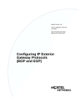
Center entity. Figure 1-1 depicts a sample internet segmented into three
autonomous systems.
308628-14.00 Rev 00
1-1
Configuring IP Exterior Gateway Protocols (BGP and EGP)
Router
2
LAN
A
LAN
B
Autonomous
system 2
Router
1
Router
4
Router
3
LAN
C
Router
5
Autonomous
system 3
Router
8
Autonomous
system 1
Router
7
LAN
G
LAN
F
Router
9
LAN
D
Router
6
LAN
E
IP0006A
Figure 1-1.
An Internet Connecting Three Autonomous Systems
The routers at the edges (or borders) of autonomous systems are called gateways.
These gateways use exterior gateway protocols to exchange reachability
information and to route packets between routing domains. This guide describes
how to configure and use the Border Gateway Protocol (BGP) and the Exterior
Gateway Protocol (EGP). You do not have to configure BGP to use EGP or EGP
to use BGP.
1-2
308628-14.00 Rev 00
Exterior Gateway Protocols (BGP/EGP)
Border Gateway Protocol (BGP)
The Border Gateway Protocol (BGP) is an exterior gateway protocol that border
routers use to exchange network reachability information with other BGP
systems. BGP routers form peer relationships with other BGP routers. Using an
entity called a BGP speaker, BGP peers transmit and receive current routing
information over a reliable transport layer connection, making periodic updates
unnecessary. BGP can be used both within and between autonomous systems.
BGP peers exchange complete routing information only when they establish the
peer connection. Thereafter, BGP peers exchange routing information in the form
of routing updates. An update includes a network number, a list of autonomous
systems that the routing information has passed through (the AS path), and other
path attributes that describe the route to a set of destination networks. When
multiple paths are available, BGP compares the path attributes to choose the
preferred path.
In addition to exchanging BGP information between autonomous systems, you
can use BGP to exchange BGP information between routers in the same AS. To
differentiate between these uses, the latter is called interior BGP (IBGP).
Exterior Gateway Protocol (EGP)
You use the Exterior Gateway Protocol to exchange network reachability
information between routers in different autonomous systems. An interior
gateway protocol (IGP), such as RIP or OSPF, is used within an AS to facilitate
the communication of routing information within an autonomous system. The
routers that serve as the end points of a connection between two autonomous
systems also run an exterior gateway protocol, such as EGP-2.
Routers establish EGP neighbor relationships to periodically exchange reliable
network reachability information. EGP neighbors exchange complete reachability
information, not just updates. The router uses this information to maintain a list of
gateways, the networks the gateways can reach, and the corresponding distances.
Chapter 10, “Customizing EGP Services,” describes the use of EGP.
308628-14.00 Rev 00
1-3
Configuring IP Exterior Gateway Protocols (BGP and EGP)
Classless Interdomain Routing
Classless interdomain routing (CIDR) is an addressing scheme that uses supernet
addresses to represent multiple IP destinations. Rather than advertise a separate
route for each destination in a supernet, a router can use a supernet address to
advertise a single route -- called an aggregate route -- that represents all of the
destinations. This reduces the size of the routing tables used to store advertised IP
routes. BGP-4 supports classless interdomain routing.
BGP Concepts and Terminology
BGP is an exterior gateway protocol designed to exchange network reachability
information with other BGP systems in other autonomous systems or within the
same autonomous system.
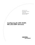
Figure 1-2 shows two autonomous systems: AS1 and AS2. Networks within AS1
and AS2 are connected by routers running an interior gateway protocol -- in this
case, OSPF. The two ASs are connected by routers that run an exterior gateway
protocol -- BGP -- in addition to OSPF.
AS1
AS2
OSPF
OSPF
OSPF
OSPF
OSPF/
BGP
BGP
connection
OSPF/
BGP
OSPF
IP00025A
Figure 1-2.
1-4
BGP Connecting Two Autonomous Systems Running OSPF
308628-14.00 Rev 00
Exterior Gateway Protocols (BGP/EGP)
Nortel Networks supports BGP-3 and BGP-4:
•
BGP-3 assumes that each advertised network is a natural class network (A, B,
or C), based on its high-order bits. BGP-3 cannot advertise subnets or
supernets.
•
BGP-4 has no concept of address classes. Each network listed in the network
layer reachability information (NLRI) portion of an update message contains
a prefix length field, which describes the length of the mask associated with
the network. This allows for both supernet and subnet advertisement. The
supernet advertisement is what makes classless interdomain routing (CIDR)
possible.
In addition, BGP-4 supports BGP confederations and TCP MD5 message
authentication.
This chapter covers the following topics:
Topic
Page
Peer-to-Peer Sessions
1-5
Stub and Multihomed Autonomous Systems
1-6
Interior BGP Routing
1-6
IBGP Route Reflector
1-7
Equal-Cost Multipath
1-8
BGP Updates
1-8
BGP/OSPF Interaction
1-10
BGP-4 Confederations
1-10
BGP-4 TCP MD5 Message Authentication
1-11
BGP Implementation Notes
1-11
Peer-to-Peer Sessions
A BGP router employs a BGP speaker, which is an entity within the router that
transmits and receives BGP messages and acts upon them. A BGP speaker forms
a neighbor relationship with another BGP speaker by establishing a peer-to-peer
session. See Chapter 6, “Establishing a Peer-to-Peer Session.”
308628-14.00 Rev 00
1-5
Configuring IP Exterior Gateway Protocols (BGP and EGP)
Stub and Multihomed Autonomous Systems
An autonomous system can include one or more BGP speakers that establish
peer-to-peer sessions with BGP speakers in other autonomous systems to provide
external route information for the networks within the AS. An AS containing
multiple BGP speakers is considered to be a multihomed AS. An AS containing a
single BGP speaker that establishes a peer-to-peer session with a single external
BGP speaker is a stub AS. The BGP speaker provides external route information
only for the networks contained within its own AS.
Interior BGP Routing
Nortel Networks implements Interior BGP (IBGP) intra-AS routing. Under IBGP,
each router in the AS runs an interior gateway protocol (IGP), such as OSPF, for
internal routing updates and also maintains an IBGP connection to each BGP
border router. The IBGP information, along with the IGP route to the originating
BGP border router, determines the next hop to use for external networks.
The IGP carries no BGP information. Each router uses IBGP exclusively to
determine reachability to external networks. When an IBGP update for a network
is received, it can be passed on to IP for inclusion in the routing table only if a
viable IGP route to the correct border gateway is available.
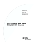
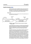
An AS with more than one BGP speaker can use IBGP to provide a transit service
for networks outside the AS. An AS that provides such a service for BGP speakers
is known as a transit AS (see Figure 1-3).
1-6
308628-14.00 Rev 00
Exterior Gateway Protocols (BGP/EGP)
AS 50
AS 10
AS 12
AS 11
BGP B
BGP A
IGP
AS 20
BGP C
AS 30
IP0021A
Figure 1-3.
Transit AS
In Figure 1-3, AS 20 is the transit AS. It provides information about its internal
networks, as well as transit networks, to the remaining ASs. The IBGP
connections between BGP routers A, B, and C are necessary to provide consistent
information to the ASs.
IBGP Route Reflector
A BGP router configured for IBGP must establish a peer-to-peer session with
every other IBGP speaker in the AS. In an AS with a large number of IBGP
speakers, this full-mesh topology can result in high bandwidth and maintenance
costs. For example, a full-mesh topology for an AS with 50 IBGP speakers
requires 1225 internal peer-to-peer connections.
308628-14.00 Rev 00
1-7
Configuring IP Exterior Gateway Protocols (BGP and EGP)
To avoid the high costs of a full-mesh topology to support IBGP speakers within a
large AS, you can configure a router to function as an IBGP route reflector (RR).
An IBGP speaker that needs to communicate with other BGP speakers in the AS
establishes a single peer-to-peer RR client session with the IBGP route reflector.
For information about the IBGP route reflector, see Chapter 8, “Configuring a
Route Reflector.”
Equal-Cost Multipath
BGP equal-cost multipath (ECMP) support allows a BGP speaker to perform
route balancing within an AS by using multiple equal-cost routes submitted to the
routing table by OSPF or RIP. For more information about BGP equal-cost
multipath, see Configuring IP Multicasting and Multimedia Services.
BGP Updates
BGP-3 and BGP-4 speakers exchange routing updates that include a network
number and a list of autonomous systems that the routing information has passed
through (the AS path).
In addition, an update includes the following:
1-8
•
List of path attributes
•
Local preference value -- BGP-4 only (described in Chapter 5, “Configuring
and Customizing BGP”)
308628-14.00 Rev 00
Exterior Gateway Protocols (BGP/EGP)
Path Attributes
A BGP-3 update message contains a variable-length sequence of path attributes,
each attribute consisting of an attribute value and an attribute description.
Table 1-1 describes the mandatory and optional BGP-3 path attributes.
Table 1-1.
BGP-3 Path Attributes
Attribute
Description
AS path
Mandatory attribute containing a list of the ASs that must be traversed
to reach the given destinations
Origin
Mandatory attribute containing one of the following values:
• IGP (the path is valid all the way to the IGP of the originating AS)
• EGP (the path was advertised using EGP by the last AS in the AS
path)
• Incomplete (the path is valid only to the last AS in the AS path)
Next hop
Mandatory attribute that defines the IP address of the router to use as a
next hop for the advertised destinations
Inter-AS
Optional attribute used to choose between paths to the destinations
listed
Unreachable
Discretionary attribute used to indicate destinations that have become
unreachable
The BGP-4 update message has the same format and mandatory attributes as the
BGP-3 update message, with the following additions:
•
In place of the unreachable attribute that BGP-3 includes as part of the path
attribute description, the BGP-4 update includes an unreachable field. This
field specifies destinations that have become unreachable.
•
In place of the BGP-3 optional attributes, a BGP-4 update message can
include the optional attributes described in Table 1-2.
Table 1-2.
BGP-4 Optional Path Attributes
Attribute
Description
Multiexit discriminator
Chooses between paths to the destinations listed
Local preference
Allows AS border routers to indicate the preference
they have assigned to a chosen route when
advertising it to IBGP peers
(continued)
308628-14.00 Rev 00
1-9
Configuring IP Exterior Gateway Protocols (BGP and EGP)
Table 1-2.
BGP-4 Optional Path Attributes (continued)
Attribute
Description
Atomic aggregate
Ensures that certain network layer reachability
information (NLRI) is not deaggregated
Aggregator
Identifies which AS performed the most recent route
aggregation. The attribute contains the last AS
number that formed the aggregate route followed by
the IP address of the BGP speaker that formed the
aggregate route.
Route clusters
Lists the route clusters that may be traversed to
reach a given destination
Advertiser
Identifies which border router injected the route
BGP community
Identifies the communities to which the route
belongs. (A community is a group of destinations that
share some common property.)
BGP/OSPF Interaction
RFC 1403 defines the interaction between BGP and OSPF when OSPF is the IGP
within an autonomous system. For routers running both protocols, the OSPF
router ID and the BGP identifier must be an IP address and must be identical. A
route policy must be configured to allow BGP advertisement of OSPF routes.
Interaction between BGP-4 and OSPF includes the ability to advertise supernets
to support classless interdomain routing (CIDR). BGP-4 allows interdomain
supernet advertisements; OSPF can carry supernet advertisements within a
routing domain.
BGP-4 Confederations
The BGP confederation feature can reduce the size and complexity of an IBGP
mesh by breaking large autonomous systems into a confederation of smaller
subautonomous systems. This division reduces the size of IBGP meshes and the
complexity of the associated configuration management. Other autonomous
systems view the confederation as a single autonomous system with the
confederation ID as its AS number. BGP confederations are available only with
BGP-4. The BGP-4 confederation feature complies with RFC 1965 and provides
the following functions:
1-10
308628-14.00 Rev 00
Exterior Gateway Protocols (BGP/EGP)
•
Lets you configure a confederation ID on the router
•
Implements new AS_PATH segment types
•
Lets you configure new AS_PATH variables, AS_CONFED_SET and
AS_CONFED_SEQUENCE, for specifying confederation parameters
•
Implements correct AS_PATH setting and manipulation to neighboring
autonomous systems that are within and outside the confederation
See “Configuring BGP-4 Confederations” on page 5-17 for a detailed description
of this feature and for configuration information.
BGP-4 TCP MD5 Message Authentication
BGP-4 lets you configure the authentication of BGP messages by TCP MD5
signatures, in compliance with RFC 2385, “Protection of BGP Sessions via the
TCP MD5 Signature Option.” When BGP authentication is enabled, a BGP
speaker can verify that the BGP messages it receives from its peers are actually
from a peer and not from a third party masquerading as a peer.
See “Configuring and Enabling MD5 Authentication” on page 5-21 for a detailed
description of this feature and for configuration information.
BGP Implementation Notes
The guidelines in the following list are crucial to successful BGP configuration.
Caution: If you do not follow these guidelines, BGP either will not work
efficiently or will become disabled on the interfaces involved.
•
BGP will not operate with an IP router in nonforwarding (host-only) mode.
Make sure that the routers you want BGP to operate with are in forwarding
mode.
•
If you are using BGP for a multihomed AS (one that contains more than one
exit point), Nortel Networks strongly encourages you to use OSPF for your
IGP and BGP for your sole exterior gateway protocol, or use intra-AS IBGP
routing.
308628-14.00 Rev 00
1-11
Configuring IP Exterior Gateway Protocols (BGP and EGP)
If OSPF is the IGP, you should also use the default OSPF tag construction.
Using EGP or modifying the OSPF tags makes network administration and
proper construction of BGP path attributes more difficult.
•
For any router supporting both BGP and OSPF, the OSPF router ID and the
BGP identifier must be the same.
For information about configuring OSPF, see Configuring IP, ARP, RARP, RIP,
and OSPF Services.
1-12
308628-14.00 Rev 00
Chapter 2
Starting BGP Services with the BCC
This chapter describes how to use the BCC to start the following services with a
basic configuration -- that is, a configuration using all available default values.
Topic
Page
Starting IP
2-1
Starting BGP
2-3
Starting IP
To start IP on the router, you must:
1. Configure a physical interface on an available slot/connector.
2. Configure an IP interface on the physical interface.
Step 1: Configuring a Physical Interface
To configure a physical interface on a slot and connector, navigate to the top-level
box prompt and enter:
<interface_type> slot <slot_number> connector <connector_number>
interface_type is the name of a link module on the router.
slot_number is the number of the slot on which the link module is located.
connector_number is the number of a connector on the link module.
308628-14.00 Rev 00
2-1
Configuring IP Exterior Gateway Protocols (BGP and EGP)
For example, the following command configures an Ethernet interface on slot 2,
connector 2:
box# ethernet slot 2 connector 2
ethernet/2/2#
Step 2: Configuring an IP Interface
To configure an IP interface on a physical interface, navigate to the prompt for the
physical interface and enter:
ip address <address> mask <mask>
address and mask are a valid IP address and its associated mask, expressed in
dotted-decimal notation.
For example, the following command configures IP interface 2.2.2.2/255.0.0.0 on
an Ethernet physical interface on slot 2, connector 2:
ethernet/2/2# ip address 2.2.2.2 mask 255.0.0.0
ip/2.2.2.2/255.0.0.0#
The IP interface is configured on the Ethernet interface with default values for all
interface parameters. When you configure an IP interface, the BCC also
configures IP globally on the router with default values for all IP global
parameters.
You customize IP by modifying IP global and interface parameters as described in
Chapter 4, “Configuring and Customizing IP for BGP.”
2-2
308628-14.00 Rev 00
Starting BGP Services with the BCC
Starting BGP
To start BGP:
1. Configure BGP on the router.
2. Define a BGP peer-to-peer connection.
Step 1: Configuring Global BGP
To configure BGP on the router, navigate to the global IP prompt and enter:
bgp
BGP is now running on the router with default values for all BGP parameters. You
customize BGP by modifying BGP parameters as described in Chapter 5,
“Configuring and Customizing BGP.”
Step 2: Defining a Peer-to-Peer Connection
BGP exchanges routing information with BGP peers located in another
autonomous system (AS) or within the same AS.
To define a peer-to-peer connection, navigate to the BGP prompt and enter:
peer local <local_ip_address> remote <remote_ip_address> as <as_number>
local_ip_address is the address, expressed in dotted-decimal format, of an IP
interface on the local router.
remote_ip_address is the address of an IP interface on the remote peer’s router.
as_number is the number of the AS in which the remote peer is located.
For example, the following command defines a peer-to-peer connection between
local IP interface 2.3.3.3 and remote interface 2.3.3.4. The remote BGP peer is
located in AS 4.
bgp# peer local 2.3.3.3 remote 2.3.3.4 as 4
peer/2.3.3.3/2.3.3.4#
The BGP peer-to-peer relationship is established with default values for all BGP
peer parameters. You customize the peer-to-peer connection by modifying BGP
peer parameters as described in Chapter 6, “Establishing a Peer-to-Peer Session.”
308628-14.00 Rev 00
2-3
Chapter 3
Starting BGP and EGP Services with Site Manager
This chapter describes how to use Site Manager to start the following IP services
using a basic configuration -- that is, a configuration using only default values.
Topic
Page
Starting IP and BGP
3-1
Starting EGP
3-4
Using the Circuitless IP Interface
3-6
Configuring an Unnumbered IP Interface
3-7
Starting IP and BGP
You must start BGP as part of starting IP. Before you can select a protocol to run
on the router, you must configure a circuit that the protocol can use as an interface
to an attached network. For information and instructions, see Configuring WAN
Line Services and Configuring Ethernet, FDDI, and Token Ring Services.
The instructions in this chapter show you how to start IP and BGP using default
values.
308628-14.00 Rev 00
3-1
Configuring IP Exterior Gateway Protocols (BGP and EGP)
When you have successfully configured the circuit, the Select Protocols window
opens. Complete the steps in the following table:
Site Manager Procedure
You do this
System responds
1. In the Select Protocols window, select the
following protocols:
• IP
• BGP
Then click on OK.
The IP Configuration window opens.
2. Set the following parameters:
• IP Address
• Subnet Mask
• Transmit Bcast Addr
• UnNumbered Assoc Address
Click on Help or see the parameter
descriptions beginning on page A-28.
3. Click on OK.
The BGP Configuration window opens.
4. Set the following parameters:
• Identifier
• Local AS
Click on Help or ee the parameter
descriptions on page A-2.
5. Click on OK.
The BGP Peer window opens.
6. Set the following parameters:
• Peer Address
• Peer AS
• Local Address
• Peer Mode
Click on Help or see the parameter
descriptions beginning on page A-10.
7. Click on OK.
Site Manager enables default BGP
service.
For information about unnumbered interfaces, see “Configuring an Unnumbered
IP Interface” on page 3-7.
You customize IP and BGP by modifying IP parameters. For information, see
Chapter 4, “Configuring and Customizing IP for BGP.”
3-2
308628-14.00 Rev 00
Starting BGP and EGP Services with Site Manager
Deleting BGP from the Router
You can delete BGP from all router circuits on which it is currently enabled.
To delete BGP, complete the following steps:
Site Manager Procedure
You do this
System responds
1. In the Configuration Manager window,
choose Protocols.
The Protocols menu opens.
2. Choose IP.
The IP menu opens.
3. Choose BGP.
The BGP menu opens.
4. Choose Delete BGP.
Site Manager opens a window prompting,
Do you really want to delete BGP?
5. Click on OK.
Site Manager removes BGP from all circuits
on the router, and returns you to the
Configuration Manager window.
Deleting BGP-3 and BGP-4 from the Router
You can delete BGP-3 and BGP-4 from all router circuits on which they are
currently enabled. To delete BGP-3, complete the following steps:
Site Manager Procedure
You do this
System responds
1. In the Configuration Manager window, The Protocols menu opens.
choose Protocols.
2. Choose IP.
The IP menu opens.
3. Choose BGP.
The BGP menu opens.
4. Choose Delete BGP-3.
Site Manager opens a window prompting, Do
you really want to delete BGP3?
5. Click on OK.
Site Manager removes BGP-3 from all
circuits on the router, and returns you to the
Configuration Manager window.
308628-14.00 Rev 00
3-3
Configuring IP Exterior Gateway Protocols (BGP and EGP)
To delete BGP-4, complete the following steps:
Site Manager Procedure
You do this
System responds
1. In the Configuration Manager window,
choose Protocols.
The Protocols menu opens.
2. Choose IP.
The IP menu opens.
3. Choose BGP.
The BGP menu opens.
4. Choose Delete BGP-4.
Site Manager opens a window prompting,
Do you really want to delete
BGP4?
5. Click on OK.
Site Manager removes BGP-4 from all
circuits on the router, and returns you to
the Configuration Manager window.
Starting EGP
Before you can select a protocol to run on the router, you must configure a circuit
that the protocol can use as an interface to an attached network. For information
and instructions, see Configuring WAN Line Services and Configuring Ethernet,
FDDI, and Token Ring Services.
3-4
308628-14.00 Rev 00
Starting BGP and EGP Services with Site Manager
When you have successfully configured the circuit, the Select Protocols window
opens. Complete the steps in the following table:
Site Manager Procedure
You do this
System responds
1. In the Select Protocols window, select the
following protocols:
• IP
• EGP
Then click on OK.
The IP Configuration window opens.
2. Set the following parameters:
• IP Address
• Subnet Mask
• Transmit Bcast Addr
• UnNumbered Assoc Address
Click on Help or see the parameter
descriptions beginning on page A-28.
3. Click on OK.
The EGP Configuration window opens.
4. Set the following parameters:
• Local Autonomous System ID
(decimal)
• Remote Peer IP Address
• Gateway Mode
Click on Help or see the parameter
descriptions beginning on page A-24.
5. Click on OK.
308628-14.00 Rev 00
Site Manager enables EGP service, and
returns you to the Configuration Manager
window.
3-5
Configuring IP Exterior Gateway Protocols (BGP and EGP)
Deleting EGP from the Router
You can delete EGP from all router circuits on which it is currently enabled. To
delete EGP, complete the following steps:
Site Manager Procedure
You do this
System responds
1. In the Configuration Manager window,
choose Protocols.
The Protocols menu opens.
2. Choose IP.
The IP menu opens.
3. Choose EGP.
The BGP menu opens.
4. Choose Delete EGP.
Site Manager opens a window prompting, Do
you really want to delete EGP?
5. Click on OK.
Site Manager removes EGP from all circuits
on the router, and returns you to the
Configuration Manager window.
Customizing EGP
The instructions in this chapter show you how to start EGP using default values.
For information about modifying EGP default values, see Chapter 10,
“Customizing EGP Services.”
Using the Circuitless IP Interface
A circuitless IP interface has an IP address that does not map to a specific circuit.
If one or more of the router’s IP interfaces becomes disabled, this circuitless
feature ensures that the router is always reachable using the circuitless IP interface
address, as long as a viable path to the router exists. The IP router can support one
circuitless IP interface.
IP traffic travels to and from the circuitless interface as it does to any other IP
interface. In addition, the circuitless IP interface can receive packets from any
application.
When you configure a circuitless IP interface, note the following:
•
3-6
You can configure one circuitless IP interface per router. Additional circuitless
IP interfaces will not initialize.
308628-14.00 Rev 00
Starting BGP and EGP Services with Site Manager
•
You can add BGP to a circuitless interface.
•
You must assign a unique IP address and subnetwork number to the circuitless
IP interface.
•
You cannot configure a circuitless IP interface in nonforwarding mode.
For information about using a circuitless interface for a BGP peer-to-peer session,
see “Defining a Peer-to-Peer Session” on page 6-2.
Configuring an Unnumbered IP Interface
IP lets you configure an interface on a point-to-point connection without using an
IP address. Such an interface is called an unnumbered interface. Point-to-point
connections using unnumbered interfaces can be configured to advertise IBGP
and static routes.
You associate each unnumbered interface with the IP address of any numbered
interface on the router, including the circuitless interface. The router can support
multiple unnumbered interfaces, and multiple unnumbered interfaces can be
associated with the same IP address.
Because all traffic over an unnumbered interface uses broadcast addressing at the
link layer, neither an adjacent host specification nor address resolution is required.
Using BGP Peers with an Unnumbered Interface
BGP peers cannot be configured directly on an unnumbered interface.
For information about using Site Manager to configure a BGP peer-to-peer
session on routers connected through unnumbered interfaces, see “Configuring
Peers over an Unnumbered Point-to-Point Link” on page 6-19.
As with routes learned over numbered interfaces, IP stores each route learned over
an unnumbered interface in the routing table.
308628-14.00 Rev 00
3-7
Configuring IP Exterior Gateway Protocols (BGP and EGP)
The routing-table entry for a route learned over an unnumbered interface contains
the following values:
Next-hop address
0
Next-hop mask
0
Next-hop interface
Circuit number of the unnumbered interface
Note: Unnumbered interfaces cannot be pinged directly. For this reason, such
interfaces can make it difficult to diagnose router problems.
3-8
308628-14.00 Rev 00
Chapter 4
Configuring and Customizing IP for BGP
You customize IP services for BGP by setting the BGP-related IP parameters.
Customizing IP Global Parameters
When you configure an IP interface on a slot, IP is automatically configured
globally on the slot with default values for all global parameters. You customize
global IP by modifying global IP parameters as described under the following
topics:
Topic
Page
Navigating the BCC to the IP Global Prompt
4-2
Opening the Site Manager Window for IP Global Parameters
4-3
Disabling and Reenabling Global IP
4-3
Configuring the Router for Forwarding Mode
4-4
Enabling Equal-Cost Multipath Support
4-5
Enabling ISP Mode on the Router
4-7
308628-14.00 Rev 00
4-1
Configuring IP Exterior Gateway Protocols (BGP and EGP)
Navigating the BCC to the IP Global Prompt
Beginning at the top-level box prompt, enter:
ip
The IP global prompt appears.
To display the current values for all IP global parameters, enter:
info
For example, the following command sequence invokes the IP global prompt and
displays current values for IP global parameters:
box# ip
ip# info
on box
state enabled
forwarding forwarding
ttl 30
cache-timeout default
mib-table route
all-subnets disabled
classless disabled
max-policies 32
route-filters enabled
rip-max-paths 1
ecmp-method disabled
isp-mode disabled
ospf-max-paths 1
icmp-error-limit 0
ip#
4-2
308628-14.00 Rev 00
Configuring and Customizing IP for BGP
Opening the Site Manager Window for IP Global Parameters
Use the following Site Manager procedure to open the IP Global Parameters
window, which displays all IP global parameters and their current values:
Site Manager Procedure
You do this
System responds
1. In the Configuration Manager window,
choose Protocols.
The Protocols menu opens.
2. Choose IP.
The IP menu opens.
3. Choose Global.
The Edit IP Global Parameters window
opens.
Disabling and Reenabling Global IP
IP is enabled on the slot by default. You can change the state of IP as required.
Using the BCC
Navigate to the IP global prompt and enter:
state <state>
state is one of the following:
enabled (default)
disabled
For example, the following command disables IP on the router:
ip# state disabled
ip#
308628-14.00 Rev 00
4-3
Configuring IP Exterior Gateway Protocols (BGP and EGP)
Using Site Manager
Site Manager Procedure
You do this
System responds
1. In the Configuration Manager window,
choose Protocols.
The Protocols menu opens.
2. Choose IP.
The IP menu opens.
3. Choose Global.
The Edit IP Global Parameters window
opens.
4. Set the Enable parameter. Click on Help
or see the parameter description on page
A-44.
5. Click on OK.
Site Manager returns you to the
Configuration Manager window.
Configuring the Router for Forwarding Mode
By default, IP forwards all packets that are not addressed to itself. Use the
forwarding mode to direct the IP router to route (forward) IP traffic. Forwarding
configures the IP router to process all broadcast packets and all IP packets
explicitly addressed to it, and to route all other IP packets.
Note: BGP will not operate with an IP router in not-forwarding (host-only)
mode. Make sure that the routers you want BGP to operate with are in
forwarding mode.
You can use the BCC or Site Manager to select the forwarding mode.
Using the BCC
Navigate to the IP global prompt and enter:
forwarding <mode>
mode is one of the following:
forwarding (default)
notforwarding
4-4
308628-14.00 Rev 00
Configuring and Customizing IP for BGP
For example, the following command puts the router in forwarding mode:
ip# forwarding forwarding
ip#
Using Site Manager
Site Manager Procedure
You do this
System responds
1. In the Configuration Manager window,
choose Protocols.
The Protocols menu opens.
2. Choose IP.
The IP menu opens.
3. Choose Global.
The Edit IP Global Parameters window
opens.
4. Set the Forwarding parameter. Click on
Help or see the parameter description on
page A-44.
5. Click on OK.
Site Manager returns you to the
Configuration Manager window.
Enabling Equal-Cost Multipath Support
By default, IP stores the best next hop to a destination in the routing table. If
traffic arrives on an interface, IP determines the best route to the destination and
forwards all packets out the next-hop interface.
IP equal-cost multipath support (ECMP) is a load-balancing feature that allows IP
to distribute traffic over multiple (up to five) equal-cost paths to the same
destination.
IP supports three methods of distribution for equal-cost routes:
•
Round-robin distribution. IP forwards each packet to a different next hop until
it reaches the end of the list of available next hops; then it repeats the list.
Round-robin distribution makes full use of available resources but may cause
packets to be delivered out of order.
•
Source-destination hash distribution based on the source and destination
address. IP forwards all packets with a given source and destination address to
the same next hop. This method increases the chances that the packets will be
delivered in order.
308628-14.00 Rev 00
4-5
Configuring IP Exterior Gateway Protocols (BGP and EGP)
•
Destination-hash distribution based on the destination address only. IP
forwards all packets with a given destination address to the same next hop.
By default, in cases where IBGP uses the IP routing table to determine the next IP
hop to an IBGP peer, IBGP does not consider equal-cost multipath routes
submitted by RIP or OSPF. For more information about using ECMP for load
balancing, see Chapter 9, “Configuring Route and Traffic-Load Balancing.”
By default, equal-cost multipath support is disabled on the router. You can use the
BCC or Site Manager to enable the feature and choose a distribution method.
Note: To configure equal-cost multipath (ECMP) for BGP, you may also have
to configure ECMP for RIP, OSPF, or static routes.
Using the BCC
Navigate to the IP global prompt and enter:
ecmp-method <method>
method is one of the following:
disabled (default)
roundRobin
srcDestHash
destinationHash
4-6
308628-14.00 Rev 00
Configuring and Customizing IP for BGP
Using Site Manager
Site Manager Procedure
You do this
System responds
1. In the Configuration Manager window,
choose Protocols.
The Protocols menu opens.
2. Choose IP.
The IP menu opens.
3. Choose Global.
The Edit IP Global Parameters window
opens.
4. Set the Multiple Nexthop Calculation
Method parameter. Click on Help or see
the parameter description on page A-49.
5. Click on OK.
Site Manager returns you to the
Configuration Manager window.
Enabling ISP Mode on the Router
IP provides an Internet service provider (ISP) mode of operation. In ISP mode, IP
does the following:
•
Enables BGP as a soloist. By default, BGP runs as a soloist on all slots
configured with IP interfaces.
•
Disables IP forwarding caches. By default, IP maintains a forwarding cache
on each IP interface. IP maintains this table as a cache for routes that are
frequently used to forward data packets that arrive on the interface. However,
if the number of frequently used routes exceeds the size of the forwarding
table, the router continually updates the forwarding cache by removing old
routes and installing new route entries. ISP mode disables all forwarding
caches on all IP interfaces and optimizes the routing table to allow direct
forwarding, avoiding the overhead of cache misses and cache updates. If you
choose ISP mode, you do not have to explicitly disable the forwarding tables
on each interface.
308628-14.00 Rev 00
4-7
Configuring IP Exterior Gateway Protocols (BGP and EGP)
The following parameter settings also help to optimize router performance and
operation:
IP Parameter
Setting
Route Filter Support
Disabled
Maximum Policy Rules Set as required
Estimated Networks
Set as required
Redirect
Disabled at router interconnection points
By default, ISP mode features are disabled on the router. You can use the BCC or
Site Manager to enable and disable ISP mode as required.
Using the BCC
Navigate to the IP global prompt and enter:
isp-mode <state>
state is one of the following:
enabled
disabled (default)
Using Site Manager
Site Manager Procedure
You do this
System responds
1. In the Configuration Manager window,
choose Protocols.
The Protocols menu opens.
2. Choose IP.
The IP menu opens.
3. Choose Global.
The Edit IP Global Parameters window
opens.
4. Set the Enable ISP Mode Support
parameter to Enable. Click on Help or see
the parameter description on page A-50.
4-8
5. Click on OK.
The Edit Soloist Slot window opens.
6. Choose a slot and click on OK.
Site Manager returns you to the
Configuration Manager window.
308628-14.00 Rev 00
Configuring and Customizing IP for BGP
Defining a Static Route
A static route is a manually configured route that specifies the transmission path a
datagram must follow, based on the datagram’s destination address. A static route
specifies a transmission path to another network. You configure a static route if
you want to restrict datagrams to paths you specifically configure.
Static routes remain in IP routing tables until you remove them. Note, however,
that if the interface that was used to reach the next hop in the static route becomes
disabled, the static route disappears from the IP routing table.
You can use the BCC or Site Manager to specify the following:
•
The state (active or inactive) of the static route record in the IP routing tables.
•
The IP address of the network to which you want to configure the static route.
•
The subnet mask of the destination network.
•
The number of router hops a datagram can traverse before reaching the
destination IP address. The IP router uses the cost value when determining the
best route for a datagram to follow.
•
The IP address of the next-hop router.
•
The subnet mask of the next-hop router.
•
A weighted value (from 1 to 16, with 16 being the most preferred) that the IP
router uses to choose a route when its routing tables contain multiple routes to
the same destination.
•
The local router circuit associated with the static route over an unnumbered
interface.
IP supports multiple static routes to the same destination. IP uses the best route to
forward packets, and treats the other routes as backup routes in case the chosen
route becomes unusable or is no longer considered the best route.
You can also configure IP to support equal-cost multipath (ECMP) routes for
traffic load balancing. If IP considers the ECMP routes to be the best routes, IP
uses them all in the way you specify -- in round-robin fashion, for example -- to
forward data. For information, see “Enabling Equal-Cost Multipath Support” on
page 4-5. With ECMP enabled globally on the router, you can configure up to 12
ECMP static routes.
308628-14.00 Rev 00
4-9
Configuring IP Exterior Gateway Protocols (BGP and EGP)
Note: When you dynamically create a new static route (for example,
128.10.8.0/255.255.255.0/1), the router can generate the following error
message in the router log file:
# 2: 04/16/98 09:44:24.096 WARNING SLOT 5 IP Code: 56
Error when configuring static route 128.10.8.0/255.255.255.0/1
This message indicates that the static route is not configured at the time stated
because all necessary MIB sets are not completed. Error checking occurs as
each attribute is set. The router code generates the error messages to prevent
misconfigured static routes. You can verify that a static route has been created
correctly by issuing a get command for the valid attribute in the
wfIpStaticRouteEntry.10.* instance.
Using the BCC
Navigate to the global IP prompt and enter:
static-route address <destination> mask <ip_mask> next-hop-address
<next_hop>
destination is the destination IP address.
ip_mask is the mask of the destination IP address.
next_hop is the next-hop IP address.
The static route prompt appears.
The BCC configures a static route with default values for all static route
parameters and displays a static-route-specific prompt. You customize a static
route by modifying static route parameters. Navigate to the static-route-specific
prompt and enter:
<parameter> <value>
parameter value is one of the parameter/value pairs described in Table 4-1.
4-10
308628-14.00 Rev 00
Configuring and Customizing IP for BGP
Table 4-1.
BCC Static Route Parameters
Parameter
Values/Defaults
Meaning/Instructions
state
enabled (default)
disabled
Specifies the state (active or inactive) of the
static route record in the IP routing tables.
Select disable to make the static route
record inactive in the IP routing table; the IP
router will not consider this static route.
Select enable to make the static route
record active again in the IP routing table.
address
The destination IP
address you supplied
when you configured
the static route. You
cannot modify this
address.
Specifies the IP address of the network to
which you want to configure the static route.
Enter the destination IP address in
dotted-decimal notation. To configure a
default route, enter 0.0.0.0. To configure a
black hole static route, enter a supernet
address. You can configure up to 12 static
routes to the same destination.
mask
The destination IP
address mask you
supplied when you
configured the static
route. You cannot
modify this address
mask.
Specifies the subnet mask of the
destination network. Enter the subnet or
supernet mask in dotted-decimal notation.
To configure a default route, enter 0.0.0.0.
To configure a black hole static route, enter
a supernet mask.
next-hop-address
The next-hop IP
address mask you
supplied when you
configured the static
route. You cannot
modify this address
mask.
Specifies the IP address of the next-hop
router. Enter the IP address in
dotted-decimal notation. To configure a
black hole static route, enter
255.255.255.255. If you are configuring a
static route to an unnumbered interface,
enter 0.0.0.0.
next-hop-mask
IP address mask
Specifies the subnet mask of the next-hop
router.
(continued)
308628-14.00 Rev 00
4-11
Configuring IP Exterior Gateway Protocols (BGP and EGP)
Table 4-1.
BCC Static Route Parameters (continued)
Parameter
Values/Defaults
Meaning/Instructions
cost
1 (default) to 12
Specifies the number of router hops a
datagram can traverse before reaching the
destination IP address. The IP router uses
the cost value when determining the best
route for a datagram to follow. If you have
enabled ECMP on the router (for
information, see “Enabling Equal-Cost
Multipath Support” on page 4-5), you can
configure up to 12 equal-cost static routes.
preference
1 (default) to 16
Specifies a weighted value (from 1 to 16,
with 16 being the most preferred) that the IP
router uses to select a route when its
routing tables contain multiple routes to the
same destination.To configure a black hole
static route, enter the maximum preference
value.
For example, the following command line configures a static route to destination
3.2.4.5/255.255.0.0 with default values for static route parameters. The next-hop
address is 2.2.2.4, and the cost is set to 4 hops.
ip# static-route address 3.2.4.5 mask 255.255.0.0 next-hop-address 2.2.2.4
static-route/3.2.4.5/255.255.0.0/2.2.2.4# cost 4
static-route/3.2.4.5/255.255.0.0/2.2.2.4#
4-12
308628-14.00 Rev 00
Configuring and Customizing IP for BGP
Using Site Manager
Site Manager Procedure
You do this
System responds
1. In the Configuration Manager window,
choose Protocols.
The Protocols menu opens.
2. Choose IP.
The IP menu opens.
3. Choose Static Routes.
The IP Static Routes window opens.
4. Click on Add.
The IP Configuration window opens.
5. Set the following parameters:
• Destination IP Address
• Address Mask
• Cost
• Next Hop Addr
• Next Hop Mask
• Preference
• Unnumbered CCT Name
Click on Help or see the parameter
descriptions beginning on page A-51.
6. Click on OK.
Site Manager returns you to the IP Static
Routes window.
Defining a Static Default Route
If IP receives a data packet with a destination address that it is unable to match in
its routing table, it looks for a default route that it can use to forward the packet.
To include a default route in the routing table, create a static route with a
destination address of 0.0.0.0. For the next-hop address, specify a router that can
forward the packet to its destination.
308628-14.00 Rev 00
4-13
Configuring IP Exterior Gateway Protocols (BGP and EGP)
Defining a Static Black Hole for a Supernet
A router that advertises an aggregate route by using a supernet address to
represent multiple explicit routes must be able to discard packets that match the
supernet address but that do not match any of the explicit routes.
For example, consider a router that advertises an aggregate route using the
supernet address 192.32.0.0/255.255.248. The supernet address represents eight
specific networks: 192.32.0.0 to 192.32.7.0. After the aggregate route has been
propagated, the router receives network traffic for each of these specific
destinations.
At some point, the router loses connectivity to network 192.32.3.0, one of the
networks in the supernet. The router continues to forward traffic that matches
destinations 0.0 to 2.0 and 4.0 to 7.0. However, the router can no longer find a
complete match in the routing table for the disconnected network, 3.0. The router
must drop all traffic destined for 192.32.3.0.
To force the router to drop the packet for an unmatched destination, you configure
a special type of static route for a supernet called a black hole. To do so:
4-14
•
Enter the supernet address/mask pair as the destination IP address and address
mask.
•
To create the black hole, enter the black hole encoding (255.255.255.255) as
the next-hop address and the next-hop mask.
308628-14.00 Rev 00
Chapter 5
Configuring and Customizing BGP
Configuring BGP Globally
You configure and customize the Border Gateway Protocol (BGP) parameters as
described under the following topics:
Topic
Page
Enabling and Disabling BGP
5-2
Supplying a BGP Identifier
5-4
Identifying the Local AS
5-5
Disabling and Reenabling IBGP Support
5-6
Specifying Route Types for IBGP Advertisements
5-7
Setting the Update Interval Timer
5-9
Allowing Redundant Connections
5-10
Enabling Multihop Connections
5-11
Disabling and Reenabling Dynamic Policy Configuration
5-13
Configuring BGP as a Soloist
5-14
Associating a Route Reflector with a Cluster ID
5-15
Disabling and Reenabling Route Aggregation
5-15
Configuring BGP-4 Confederations
5-17
Enabling and Disabling Black Hole Punching
5-18
Disabling and Reenabling the BGP-4 MED Attribute
5-20
Configuring and Enabling MD5 Authentication
5-21
Disabling BayRS Local Preference Calculation and Route Selection
5-26
(continued)
308628-14.00 Rev 00
5-1
Configuring IP Exterior Gateway Protocols (BGP and EGP)
Topic
Page
Configuring BGP Message Logging
5-30
Configuring EBGP Route Flap Dampening
5-31
Enabling and Disabling BGP
When you start BGP on the router, BGP is automatically enabled for both BGP-3
and BGP-4 peer-to-peer connections.
You can use the BCC and Site Manager to disable and reenable BGP on the router.
You can also use Site Manager to disable and reenable BGP-3 and BGP-4.
Using the BCC
Navigate to the BGP prompt and enter:
state <state>
state is one of the following:
enabled (default)
disabled
5-2
308628-14.00 Rev 00
Configuring and Customizing BGP
Using Site Manager
Site Manager Procedure
You do this
System responds
1. In the Configuration Manager window,
choose Protocols.
The Protocols menu opens.
2. Choose IP.
The IP menu opens.
3. Choose BGP.
The BGP menu opens.
4. Choose BGP Global.
The Edit BGP Global Parameters window
opens.
5. Set the BGP Enable parameter. Click on
Help or see the parameter description on
page A-2.
6. Click on OK.
Site Manager returns you to the
Configuration Manager window.
7. In the Configuration Manager window,
choose Protocols.
The Protocols menu opens.
8. Choose IP.
The IP menu opens.
9. Choose BGP.
The BGP menu opens.
10. Choose BGP-3 Global.
The Edit BGP-3 Global Parameters menu
opens.
11. Set the Enable parameter. Click on Help
or see the parameter description on page
A-10.
12. Click on OK.
Site Manager returns you to the
Configuration Manager window.
13. In the Configuration Manager window,
choose Protocols.
The Protocols menu opens.
14. Choose IP.
The IP menu opens.
15. Choose BGP.
The BGP menu opens.
16. Choose BGP-4 Global.
The Edit BGP-4 Global Parameters
window opens.
17. Set the Enable parameter. Click on Help
or see the parameter description on page
A-10.
18. Click on OK.
308628-14.00 Rev 00
Site Manager returns you to the
Configuration Manager window.
5-3
Configuring IP Exterior Gateway Protocols (BGP and EGP)
Supplying a BGP Identifier
The BGP identifier is the IP address of an interface on this router.
There is no default for this parameter. You must supply a BGP ID, using the IP
address of one of the router’s IP interfaces.
You can use the BCC or Site Manager to supply a BGP identifier for the router.
Using the BCC
Navigate to the BGP prompt and enter:
router-id <ip_address>
ip_address is the address of one of the IP interfaces on the router.
For example, the following command supplies IP address 2.2.2.2 for the BGP
identifier:
bgp# router-id 2.2.2.2
bgp#
Using Site Manager
Site Manager Procedure
You do this
System responds
1. In the Configuration Manager window,
choose Protocols.
The Protocols menu opens.
2. Choose IP.
The IP menu opens.
3. Choose BGP.
The BGP menu opens.
4. Choose BGP Global.
The Edit BGP Global Parameters window
opens.
5. Set the BGP Identifier parameter. Click
on Help or see the parameter description
on page A-3.
6. Click on OK.
5-4
Site Manager returns you to the
Configuration Manager window.
308628-14.00 Rev 00
Configuring and Customizing BGP
Identifying the Local AS
Each autonomous system in the internet has a unique AS ID.
You can use the BCC or Site Manager to supply the ID of the AS in which the
BGP router is located.
Using the BCC
Navigate to the BGP prompt and enter:
local-as <local_as>
local_as is the number of the AS in which the router is located.
For example, the following command specifies AS 5 as the local AS:
bgp# local-as 5
bgp#
Using Site Manager
Site Manager Procedure
You do this
System responds
1. In the Configuration Manager window,
choose Protocols.
The Protocols menu opens.
2. Choose IP.
The IP menu opens.
3. Choose BGP.
The BGP menu opens.
4. Choose BGP Global.
The Edit BGP Global Parameters window
opens.
5. Set the BGP Local AS parameter. Click
on Help or see the parameter description
on page A-3.
6. Click on OK.
308628-14.00 Rev 00
Site Manager returns you to the
Configuration Manager window.
5-5
Configuring IP Exterior Gateway Protocols (BGP and EGP)
Disabling and Reenabling IBGP Support
By default, BGP supports IBGP intra-AS sessions. (For information, see
Chapter 1, “Exterior Gateway Protocols (BGP/EGP).”)
A BGP transit AS should use IBGP intra-AS routing. A stub or multihomed AS
usually does not use IBGP routing.
You can use the BCC or Site Manager to disable and reenable the feature.
Using the BCC
Navigate to the BGP prompt and enter:
intra-as-routing <state>
state is one of the following:
enabled (default)
disabled
For example, the following command disables IGBP:
bgp# intra-as-routing disabled
bgp#
Using Site Manager
Site Manager Procedure
You do this
System responds
1. In the Configuration Manager window,
choose Protocols.
The Protocols menu opens.
2. Choose IP.
The IP menu opens.
3. Choose BGP.
The BGP menu opens.
4. Choose BGP Global.
The Edit BGP Global Parameters window
opens.
5. Set the BGP Intra-AS parameter. Click on
Help or see the parameter description on
page A-3.
6. Click on OK.
5-6
Site Manager returns you to the
Configuration Manager window.
308628-14.00 Rev 00
Configuring and Customizing BGP
Specifying Route Types for IBGP Advertisements
If IBGP is enabled, you can specify the types of routes that BGP advertises in
IBGP sessions. By default, IBGP propagates only routes learned from external
BGP peers. You can use Site Manager to configure IBGP to propagate routes
learned from all route sources (excluding IBGP and OSPF interarea and intra-area
routes, which IBGP never advertises).
You can use the BCC or Site Manager to specify the route type for IBGP
advertisements.
Using the BCC
Navigate to the BGP global prompt and enter:
redistribute-protocols <protocols>
protocols is one of the values listed in Table 5-1.
Table 5-1.
Route Types for BGP Advertisements
Route Type
Meaning
bgp (default)
BGP propagates routes learned from external BGP peers.
all
BGP propagates routes from all route sources.
For example, the following command configures BGP to advertise routes from all
route sources:
bgp# redistribute-protocols all
bgp#
308628-14.00 Rev 00
5-7
Configuring IP Exterior Gateway Protocols (BGP and EGP)
Using Site Manager
Site Manager Procedure
You do this
System responds
1. In the Configuration Manager window,
choose Protocols.
The Protocols menu opens.
2. Choose IP.
The IP menu opens.
3. Choose BGP.
The BGP menu opens.
4. Choose BGP Global.
The Edit BGP Global Parameters window
opens.
5. Set the BGP From Protocols parameter.
Click on Help or see the parameter
description on page A-4.
6. Click on OK.
5-8
Site Manager returns you to the
Configuration Manager window.
308628-14.00 Rev 00
Configuring and Customizing BGP
Setting the Update Interval Timer
BGP injects external BGP routes into the routing table. The default minimum
interval between route injections is 5 seconds.
You can use the BCC or Site Manager to specify the minimum number of seconds
between route injections.
Using the BCC
Navigate to the BGP prompt and enter:
inject-time <seconds>
seconds is the minimum interval between route injections.
For example, the following command causes BGP to inject external BGP routes
into the routing table with a minimum interval of 10 seconds:
bgp# inject-time 10
bgp#
Using Site Manager
Site Manager Procedure
You do this
System responds
1. In the Configuration Manager window,
choose Protocols.
The Protocols menu opens.
2. Choose IP.
The IP menu opens.
3. Choose BGP.
The BGP menu opens.
4. Choose BGP Global.
The Edit BGP Global Parameters window
opens.
5. Set the BGP Interval Timer parameter.
Click on Help or see the parameter
description on page A-4.
6. Click on OK.
308628-14.00 Rev 00
Site Manager returns you to the
Configuration Manager window.
5-9
Configuring IP Exterior Gateway Protocols (BGP and EGP)
Allowing Redundant Connections
By default, BGP performs redundancy checking on peer-to-peer TCP sessions.
BGP can maintain only one TCP session with a remote BGP peer. If the remote
peer attempts to establish another session on another physical connection, BGP
rejects the session. BGP uses a collision-detection method based on the router ID
to check for redundant sessions.
The advantage of a peer-to-peer configuration with multiple sessions on multiple
physical connections is redundancy -- if one connection fails, the peers can
communicate over another link. The disadvantage is that such a configuration
results in multiple copies of each route.
You can use the BCC or Site Manager to disable redundancy checking to allow
TCP sessions with the same remote peer on multiple physical connections.
You can also use the BCC to specify the maximum number of redundant routes
that BGP allows. By default, BGP allows up to 255 redundant routes.
Using the BCC
To disable or reenable redundancy checking, navigate to the BGP prompt and
enter:
redundant-connection <state>
state is one of the following:
enabled (default)
disabled
To specify the maximum number of redundant routes, navigate to the BGP prompt
and enter:
max-redundant-routes <max_routes>
max_routes is the maximum number of redundant routes.
For example, the following command disables BGP redundancy checking,
allowing BGP to establish multiple TCP sessions (on different physical
connections) with the same remote peer:
bgp# redundant-connection disabled
bgp#
5-10
308628-14.00 Rev 00
Configuring and Customizing BGP
The following command sequence reenables redundancy checking and configures
BGP to allow up to 50 redundant routes:
bgp# redundant connection enabled
bgp# max-redundant-routes 50
bgp#
Using Site Manager
Site Manager Procedure
You do this
System responds
1. In the Configuration Manager window,
choose Protocols.
The Protocols menu opens.
2. Choose IP.
The IP menu opens.
3. Choose BGP.
The BGP menu opens.
4. Choose BGP Global.
The Edit BGP Global Parameters window
opens.
5. Set the Detect Redundant Connections
parameter. Click on Help or see the
parameter description on page A-5.
6. Click on OK.
Site Manager returns you to the
Configuration Manager window.
Enabling Multihop Connections
By default, BGP enforces the one-hop rule for BGP peers -- the remote peer must
be located on a directly attached network.
You can use the BCC or Site Manager to override the restriction and allow
multihop connections.
Caution: Enabling multihop BGP connections is dangerous because it can
cause BGP speakers to establish a BGP connection that traverses a third-party
AS, which may violate policy considerations and may also introduce
forwarding loops.
308628-14.00 Rev 00
5-11
Configuring IP Exterior Gateway Protocols (BGP and EGP)
Using the BCC
Navigate to the BGP prompt and enter:
multi-hop <state>
state is one of the following:
enabled
disabled (default)
For example, the following command enables BGP for multihop peer-to-peer
connections:
bgp# multi-hop enabled
bgp#
Using Site Manager
Site Manager Procedure
You do this
System responds
1. In the Configuration Manager window,
choose Protocols.
The Protocols menu opens.
2. Choose IP.
The IP menu opens.
3. Choose BGP.
The BGP menu opens.
4. Choose BGP Global.
The Edit BGP Global Parameters window
opens.
5. Set the Multi-hop EBGP Connection
parameter. Click on Help or see the
parameter description on page A-5.
6. Click on OK.
5-12
Site Manager returns you to the
Configuration Manager window.
308628-14.00 Rev 00
Configuring and Customizing BGP
Disabling and Reenabling Dynamic Policy Configuration
By default, BGP reconfigures IP policies dynamically. This means that if you
modify a policy, BGP dynamically reevaluates all affected routes in the light of
the modified policy. BGP then sends the appropriate withdraw or update message
to the affected peers. BGP keeps track of the routes sent to each peer, allowing for
precise determination of which routes to send and which to withdraw.
If you modify an IP policy with this feature disabled, BGP restarts all BGP
connections. There is no advantage to disabling dynamic policy configuration.
Disabling this parameter will significantly impact BGP protocol operation
overhead and network stability.
You can use the following Site Manager procedure to disable and reenable
dynamic policy configuration:
Site Manager Procedure
You do this
System responds
1. In the Configuration Manager window,
choose Protocols.
The Protocols menu opens.
2. Choose IP.
The IP menu opens.
3. Choose BGP.
The BGP menu opens.
4. Choose BGP Global.
The Edit BGP Global Parameters window
opens.
5. Set the BGP Dynamic Policy Change
Support parameter. Click on Help or see
the parameter description on page A-6.
6. Click on OK.
308628-14.00 Rev 00
Site Manager returns you to the
Configuration Manager window.
5-13
Configuring IP Exterior Gateway Protocols (BGP and EGP)
Configuring BGP as a Soloist
By default, BGP runs as a soloist on a slot determined by the BGP soloist slot
mask. Nortel Networks recommends that the slot mask include only
nonforwarding slots, so that BGP operations (route calculation, for example)
occur on one slot while the other slots maintain maximum forwarding capability.
If the slot on which the soloist is running fails, BGP runs on an eligible slot. By
default, BGP considers all slots with IP interfaces to be eligible slots. You can use
the BCC or Site Manager to specify a slot for the BGP soloist.
Using the BCC
Navigate to the BGP prompt and enter:
slot-mask <slot>
slot is one of the values listed in Table 5-2.
Table 5-2.
Slot Mask Parameter Values
Value
Meaning
all-slots (default)
BGP runs on all slots. (BGP is not a soloist.)
1 to 14
BGP is a soloist running on the specified slot.
For example, the following command causes BGP to run as a soloist on slot 5:
bgp# slot-mask 5
bgp#
5-14
308628-14.00 Rev 00
Configuring and Customizing BGP
Using Site Manager
Site Manager Procedure
You do this
System responds
1. In the Configuration Manager window,
choose Protocols.
The Protocols menu opens.
2. Choose IP.
The IP menu opens.
3. Choose BGP.
The BGP menu opens.
4. Choose BGP Global.
The Edit BGP Global Parameters window
opens.
5. Set the BGP Soloist Slots parameter.
Click on Help or see the parameter
description on page A-6.
6. Click on OK.
Site Manager returns you to the
Configuration Manager window.
Associating a Route Reflector with a Cluster ID
In an AS with multiple clusters of route reflectors, you assign a cluster ID to each
cluster and associate each route reflector with a cluster.
For information about the IBGP route reflector, see Chapter 8, “Configuring a
Route Reflector.”
Disabling and Reenabling Route Aggregation
By default, BGP aggregates non-BGP-originated subnet routes to their
corresponding natural network routes for advertisement to BGP peers.
You can use Site Manager or the BCC to disable this feature. (This switch does
not affect the advertisement of BGP-originated routes.)
308628-14.00 Rev 00
5-15
Configuring IP Exterior Gateway Protocols (BGP and EGP)
Using the BCC
Navigate to the BGP prompt and enter:
subnet-aggregation <state>
state is one of the following:
enabled (default)
disabled
For example, the following BCC command disables subnet aggregation:
bgp# subnet-aggregation disabled
bgp#
Using Site Manager
Site Manager Procedure
You do this
System responds
1. In the Configuration Manager window,
choose Protocols.
The Protocols menu opens.
2. Choose IP.
The IP menu opens.
3. Choose BGP.
The BGP menu opens.
4. Choose BGP Global.
The Edit BGP Global Parameters window
opens.
5. Set the Aggregate Subnets parameter.
Click on Help or see the parameter
description on page A-7.
6. Click on OK.
5-16
Site Manager returns you to the
Configuration Manager window.
308628-14.00 Rev 00
Configuring and Customizing BGP
Configuring BGP-4 Confederations
If this router is a member of an autonomous system that is part of a confederation,
you can configure the confederation ID for this router. You can also specify the
list of this BGP speaker’s peers in other sub-ASs within the same confederation. If
the confederation identifier is not available (nil), this AS is not a member of any
confederation. If the list of confederation peers is empty (nil), no peers to this
speaker exist among the neighbor ASs that are members of this local
confederation. You can use Site Manager or the BCC to configure this feature.
Using the BCC
To configure the BGP confederation identifier, navigate to the BGP prompt and
enter:
confederation-id <AS_number>
AS_number is any valid autonomous system number. The default is 0.
For example, the following BCC command sets the autonomous system number
to 3:
bgp# confederation-id 3
bgp#
To configure the BGP confederation peers, navigate to the BGP prompt and enter:
confederation-peers <peer_address>
peer_address is any valid IP address for a BGP peer to the router you are
configuring.
For example, the following BCC command sets the BGP peer address to 1.1.1.1:
bgp# confederation-peers 1.1.1.1
bgp#
308628-14.00 Rev 00
5-17
Configuring IP Exterior Gateway Protocols (BGP and EGP)
Using Site Manager
Site Manager Procedure
You do this
System responds
1. In the Configuration Manager window,
choose Protocols.
The Protocols menu opens.
2. Choose IP.
The IP menu opens.
3. Choose BGP.
The BGP menu opens.
4. Choose BGP Global.
The Edit BGP Global Parameters window
opens.
5. Set the Configuration ID and the
Confederation Peer parameters. Click on
Help or see the parameter descriptions
beginning on page A-8.
6. Click on OK.
Site Manager returns you to the
Configuration Manager window.
Enabling and Disabling Black Hole Punching
If BGP advertises aggregate routes, you can configure BGP to submit each
aggregate route to the routing table as a black hole. If IP receives a packet that
does not match any of the explicit subnet routes, the black hole route causes it to
discard the packet. (For more information about black hole routes, see “Defining a
Static Black Hole for a Supernet” on page 4-14.)
By default, BGP does not submit a black hole route to the IP routing table for an
aggregate route that it advertises to a BGP peer.
You can use the BCC or Site Manager to enable this feature. You can also
configure IP to return an ICMP destination unreachable message to the sender of a
packet to an unknown destination.
5-18
308628-14.00 Rev 00
Configuring and Customizing BGP
Using the BCC
Navigate to the BGP prompt and enter:
black-hole-punching <action>
action is one of the values described in Table 5-3.
Table 5-3.
Black Hole Punching Parameter Settings
Value
Meaning
disabled (default)
Disables black hole punching
drop
Enables black hole punching. IP drops packets for an unknown
destination without returning an ICMP message to the sender.
reject
Enables black hole punching. IP drops packets for an unknown
destination and returns an ICMP destination unreachable
message to the sender.
For example, the following command line causes BGP to submit aggregate routes
to the routing table as black hole routes. IP drops packets for unknown
destinations but does not return ICMP destination unreachable messages to the
sender:
bgp# black-hole-punching drop
bgp#
308628-14.00 Rev 00
5-19
Configuring IP Exterior Gateway Protocols (BGP and EGP)
Using Site Manager
Site Manager Procedure
You do this
System responds
1. In the Configuration Manager window,
choose Protocols.
The Protocols menu opens.
2. Choose IP.
The IP menu opens.
3. Choose BGP.
The BGP menu opens.
4. Choose BGP Global.
The Edit BGP Global Parameters window
opens.
5. Set the Black Hole Routes parameter.
Click on Help or see the parameter
description on page A-7.
6. Click on OK.
Site Manager returns you to the
Configuration Manager window.
Disabling and Reenabling the BGP-4 MED Attribute
By default, BGP-4 considers the multiexit discriminator (MED) attribute in the
route selection process (see Table 1-2 on page 1-9).
You can use the BCC or Site Manager to configure BGP-4 so that it disregards the
MED attribute in the route selection process.
Using the BCC
Navigate to the BGP prompt and enter:
med-comparison <state>
state is one of the following:
enabled (default)
disabled
For example, the following command causes BGP-4 to disregard the MED
attribute in an update when selecting a route:
bgp# med-comparison disabled
bgp#
5-20
308628-14.00 Rev 00
Configuring and Customizing BGP
Using Site Manager
Site Manager Procedure
You do this
System responds
1. In the Configuration Manager window,
choose Protocols.
The Protocols menu opens.
2. Choose IP.
The IP menu opens.
3. Choose BGP.
The BGP menu opens.
4. Choose BGP Global.
The Edit BGP Global Parameters window
opens.
5. Set the Route with MED parameter. Click
on Help or see the parameter description
on page A-7.
6. Click on OK.
Site Manager returns you to the
Configuration Manager window.
Configuring and Enabling MD5 Authentication
BGP-4 TCP MD5 authentication lets you configure BGP peers to ensure secure
message interchange. BGP-4 TCP MD5 message authentication provides the
following features:
•
A TCP MD5 signature can exist for BGP peers.
•
Authentication and secret keys are configurable on a per-peer basis. Peers
configured with common secret keys can authenticate each other and
exchange routing information.
•
Configurations can concurrently have BGP peers with authentication enabled
and authentication disabled.
•
Keys can be stored as either clear text or encrypted, and this storage mode can
be set on a per-peer basis.
308628-14.00 Rev 00
5-21
Configuring IP Exterior Gateway Protocols (BGP and EGP)
When BGP-4 TCP MD5 authentication is enabled, a router computes an MD5
signature for each TCP packet, based on the TCP packet and a per-peer secret key.
The router adds this MD5 signature to the TCP packet containing a BGP message
and sends it with the packet, but it does not send the secret key. The receiver of the
TCP packet also knows the secret key and can verify the MD5 signature. A third
party trying to masquerade as the sender, however, cannot generate an authentic
signature because it does not know the secret key. Configurations can
concurrently have BGP peers with authentication enabled and authentication
disabled.
The per-peer secret keys provide the security. Peers configured with common
secret keys can authenticate each other and exchange routing information. If the
keys are compromised (for example, by transfer of the configuration file), then the
authentication itself is compromised. To prevent this, the secret keys can be stored
in encrypted form in the configuration file and MIB, using the Technician
Interface secure shell to encrypt the per-peer secret keys. The secure shell uses
DES to encrypt the secret keys, and the DES key (the NPK/MEK) is stored in the
router’s nonvolatile RAM (NVRAM). The Node Protection Key/Message
Encryption Key (NPK/MEK) is configured using the Technician Interface secure
shell or the Site Manager WEP Key Manager. The TCP MD5 secret keys can
optionally be similarly encrypted.
Entering and Storing MD5 Authentication Keys
To configure BGP TCP MD5 authentication, set the wfBgpPeerTcpAuthentication
MIB object to MD5. You can then enter an optional, variable-length ASCII
authentication key for each BGP-4 peer. This key is stored in the
wfBgpPeerTcpMd5Key MIB object. Entering the authentication key also enables
authentication for the peer connection. Both peers must be configured with the
same authentication key. When an authentication key is stored in the MIB or the
configuration file, it can optionally be encrypted using DES with the NPK/MEK
key, as selected by the wfBgpPeerTcpMd5KeyStorage MIB object.
You can enter the authentication keys through Site Manager or the BCC. Use the
Technician Interface secure shell to enter the NPK/MEK.
5-22
308628-14.00 Rev 00
Configuring and Customizing BGP
Configuring BGP Authentication
You can configure BGP MD5 authentication using the BCC or Site Manager. This
guide describes how to configure the BGP TCP MD5 authentication attributes
with the BCC and Site Manager interfaces. The BCC, Site Manager, and secure
shell interfaces accept and display the authentication keys as unencrypted
character strings, regardless of whether the underlying storage is clear or
encrypted. That is, these interfaces can encrypt a key before saving it and decrypt
it before displaying it. They also handle the necessary conversion from character
string to octet string. The Technician Interface, however, displays a key just as it is
stored in the MIB.
The attributes that you must configure within the MIB entry wfBgpPeerEntry are
wfBgpTcpAuthentication, which enables authentication, wfBgpPeerTcpMd5Key
and wfBgpPeerTcpMd5KeyStorage. TCP monitors the authentication using the
attribute wfTcpConnMd5Errors in the wfTcpConnEntry record.
Initializing TCP with the MD5 Option
If an MD5 authentication key is configured for a BGP peer that has BGP
authentication enabled, then BGP reads the authentication key from the MIB,
decrypts it if necessary, and passes the unencrypted authentication key to TCP. If
there is no NPK available to decrypt an encrypted authentication key, BGP logs an
event: “BGP TCP MD5 NPK No NPK configured.” If TCP receives an MD5
authentication key, it reduces its Maximum Segment Size (MSS) by 18 octets, the
length of the TCP MD5 option. It also adds an MD5 signature to each transmitted
packet.
Generating MD5 Signatures on Transmitted BGP TCP Packets
A BGP peer calculates the MD5 signature for a BGP message on the following
elements:
•
TCP pseudo-header
•
TCP header, excluding options
•
TCP segment data
•
TCP MD5 authentication key
The peer inserts the resulting 16-byte MD5 signature into the following TCP
options: kind=19, length=18.
308628-14.00 Rev 00
5-23
Configuring IP Exterior Gateway Protocols (BGP and EGP)
Verifying MD5 Signatures on Received BGP TCP Packets
When TCP receives a packet, it checks whether the connection has been
configured for authentication. If it has, TCP verifies that the packet contains a
kind=19 option. If the packet does not contain that option, then TCP logs a “TCP
MD5 No Signature” event and discards the packet, but does not close the TCP
connection.
When TCP receives a packet with the kind=19 option, it first verifies that an MD5
authentication key has been configured for the TCP connection.
•
If the key has not been configured, TCP logs a “TCP MD5 No Key
Configured” event and discards the packet but does not close the TCP
connection.
•
If the key has been configured, TCP computes the expected MD5 signature
and compares the computed signature with the received MD5 signature. If the
signatures match, TCP sends the packet to BGP. If the signatures do not
match, TCP logs a “TCP MD5 Invalid Signature” event and discards the
packet but does not close the TCP connection.
•
The occurrence of any of these errors increments the total count of TCP
connection MD5 errors (wfTcpConnMd5Errors).
You can enter an optional, variable-length ASCII authentication key for each BGP
peer. This key is stored in the wfBgpPeerTcpMd5Key MIB object. Entering the
authentication key also enables authentication for the peer connection. Both peers
must be configured with the same authentication key. When an authentication key
is stored in the MIB or the configuration file, it can optionally be encrypted using
DES with the NPK/MEK key, as selected by the wfBgpPeerTcpMd5KeyStorage
MIB object.
By default, BGP-4 MD5 authentication is disabled.
Use the Technician Interface secure shell or the Site Manager WEP Key Manager
to enter the message encryption key/node protection key (NPK/MEK) value
before setting the MD5 authentication parameters. For information on Technician
Interface secure shell, see Configuring IPsec Services. For information on DES,
WEP, and NPK, see Configuring Data Encryption Services.You can enter the
authentication keys through Site Manager or the BCC.
5-24
308628-14.00 Rev 00
Configuring and Customizing BGP
Using the BCC
To set the BGP-4 authentication parameters, navigate to the peer prompt and
enter:
tcp-authentication <state>
state is one of the following:
none (default)
md5
For example, the following command enables BGP-4 MD5 authentication:
bgp# tcp-authentication md5
bgp#
If TCP authentication is not enabled, the other BGP authentication parameters are
irrelevant.
If you have specified MD5 authentication, you can continue configuring the
BGP-4 authentication parameters. At the peer prompt, enter:
tcp-md5-key <key>
key is the value that you assign to the MD5 key. There is no default value.
For example, the following command sets the BGP-4 MD5 key to corpkey:
bgp# tcp-md5-key corpkey
bgp#
You can also specify whether to store the key as clear text or encrypted. At the
peer prompt, enter:
tcp-md5-key-storage <format>
format is one of the following:
clear-text (default)
encrypted
For example, the following command sets the BGP-4 MD5 key storage format to
encrypted:
bgp# tcp-md5-key encrypted
bgp#
308628-14.00 Rev 00
5-25
Configuring IP Exterior Gateway Protocols (BGP and EGP)
Using Site Manager
Site Manager Procedure
You do this
System responds
1. In the Configuration Manager window,
choose Protocols.
The Protocols menu opens.
2. Choose IP.
The IP menu opens.
3. Choose BGP.
The BGP menu opens.
4. Choose BGP Peers.
The Edit BGP Global Parameters window
opens.
5. Set the following parameters:
• Tcp Authentication
• Tcp Md5 Key Storage
• Tcp Md5 Key
Click on Help or see the parameter
descriptions beginning on page A-17.
6. Click on OK.
Site Manager returns you to the
Configuration Manager window.
Disabling BayRS Local Preference Calculation and Route Selection
A BGP speaker calculates a local preference value for each route that it receives
from an external peer and passes this value as the local_pref attribute in routing
updates that it announces to its internal BGP (IBGP) peers. A BGP speaker that
receives a routing update from an IBGP peer uses the local_pref attribute in its
best-route selection process.
By default, BGP calculates a local-preference value by using the algorithm
described in “Calculating BGP-4 Local Preference Values” on page 5-27. The
best-route selection process is described in “Best-Route Selection” on page 5-28.
Different implementations of BGP have different ways of arriving at a local
preference value. However, within an AS, all BGP speakers should use the same
method to determine local preference and to select the best routes.
Note: For a comparison of the Nortel Networks BCC and Site Manager
equivalents for Cisco router configuration commands, see Appendix C,
“Translating Cisco to Nortel Networks Equivalents.”
5-26
308628-14.00 Rev 00
Configuring and Customizing BGP
If you are configuring BGP in a network that also includes routers from vendors
other than Nortel Networks, you can use the BCC or Site Manager to disable
BayRS local-preference calculation and route selection. Instead, BGP assigns a
value of 100 to externally received routes and uses the rules listed in Table 5-4 on
page 5-28 for best-route selection.
Calculating BGP-4 Local Preference Values
BGP-4 update messages contain a local preference value that an AS border router
can assign to a route when advertising it to IBGP peers. The calculation of the
local preference attribute is specific to each implementation. A higher value
indicates that the route is more preferred.
The router uses the following equation to calculate a value for the local preference
attribute:
local preference = 8191 - origin value - AS path weight
where origin value is 0 for routes with an origin path attribute of IGP or 4096 for
other routes, and AS path weight is a sum of weight values associated with AS
numbers listed in the route’s AS Path attribute. These weight values can be
configured and default to 8.
A steep penalty is applied to routes that are advertised with an origin attribute
other than IGP -- that is, EGP or incomplete.
For an OSPF internal route or a direct route, the local preference attribute is set to:
local preference = (8191 + 256 - (metric + 255))
where metric is the OSPF metric for an OSPF route or the configured cost for a
direct route.
For a RIP route, an EGP route, an OSPF ASE route, or a static route, the local
preference attribute is set to:
local preference = (256 - metric)
where metric is the RIP metric for a RIP route, the EGP metric for an EGP route,
the OSPF metric for an OSPF ASE route, or the configured cost for a static route.
Note that local preference values for OSPF internal routes and direct routes are
higher than the local preference values calculated for BGP routes.
308628-14.00 Rev 00
5-27
Configuring IP Exterior Gateway Protocols (BGP and EGP)
Best-Route Selection
BGP uses the rules in Table 5-4 as tie breakers to select the best BGP route. This
table lists the rules in the order in which they are evaluated.
Table 5-4.
Best-Route Selection Rules
Default Preference Tie-Breaker Rules
Calculated Preference Tie-Breaker Rules
1. Choose the route with the lower route weight.
2. Choose the route with the higher local preference
attribute.
3. Choose the route with the lower multiexit
discriminator (MED) attribute (if both routes
include this optional attribute).
4. Choose the route with the lower interior cost to
the next hop.
5. Choose external BGP over IBGP.
6. Choose the route with the lower BGP identifier.
7. Choose the route with the lower BGP connection
remote address.
8. Choose the route with the lower BGP connection
local address.
1. If the next hop is inaccessible, do not consider it.
2. Consider larger BGP administrative weights first.
3. If the routers have the same weight, consider the
route with the highest local preference.
4. If the routes have the same local preference,
prefer the route that the local router originated.
5. If no route was locally originated, prefer the
shorter AS path.
6. If the routes have the same AS path length,
prefer the lowest origin code (IGP is preferred
over EGP, which is preferred over incomplete).
7. If the origin codes are the same and all paths
come from the AS, prefer the path with the lowest
multiexit discriminator (MED) metric. Treat a
missing MED metric as 0.
8. If the MED metrics are the same, prefer external
paths over internal paths.
9. If IGP synchronization is disabled and only
internal paths remain, prefer the path through the
closest neighbor.
10. Prefer the route with the lowest IP address value
for the BGP router ID.
Using the BCC
Navigate to the BGP global prompt and enter:
local-pref-calculation <state>
state is one of the values shown in Table 5-5.
5-28
308628-14.00 Rev 00
Configuring and Customizing BGP
Table 5-5.
Local Preference Calculation Method
State
Meaning
enabled (default)
BGP uses BayRS formulas for local-preference calculation and
best-route selection.
disabled
BGP does not perform local-preference calculation. Instead, it
assigns a value of 100 to the route and uses a modified formula for
best-route selection.
For example, the following command disables BayRS BGP local-preference
calculation and route selection:
bgp# local-pref-calculation disabled
bgp#
Using Site Manager
Site Manager Procedure
You do this
System responds
1. In the Configuration Manager window,
choose Protocols.
The Protocols menu opens.
2. Choose IP.
The IP menu opens.
3. Choose BGP.
The BGP menu opens.
4. Choose BGP Global.
The Edit BGP Global Parameters window
opens.
5. Set the Local Pref Calculation
parameter. Click on Help or see the
parameter description on page A-8.
6. Click on OK.
308628-14.00 Rev 00
Site Manager returns you to the
Configuration Manager window.
5-29
Configuring IP Exterior Gateway Protocols (BGP and EGP)
Configuring BGP Message Logging
Site Manager allows you to control the event messages that BGP sends to the log
file by specifying:
•
Local and remote addresses of a peer-to-peer session or sessions
•
Message severity level: fault, warning, information, trace, debug, or all levels
•
BGP message type: open, update, notification, or keepalive
Use BGP message logging parameters to limit the volume of debug-level
messages that BGP generates and logs. If you allow BGP to log all debug-level
events, the messages that BGP generates will quickly overrun and overwrite the
log file.
You can use Site Manager to control BGP event messages.
Site Manager Procedure
You do this
System responds
1. In the Configuration Manager window,
choose Protocols.
The Protocols menu opens.
2. Choose IP.
The IP menu opens.
3. Choose BGP.
The BGP menu opens.
4. Choose Debug.
The Edit BGP Debug Parameters window
opens.
5. Set the following parameters:
• Peer Local/Remote
• Message Level
• Message Trace Switch
Click on Help or see the parameter
descriptions beginning on page A-22.
6. Click on OK.
5-30
Site Manager returns you to the
Configuration Manager window.
308628-14.00 Rev 00
Configuring and Customizing BGP
Configuring EBGP Route Flap Dampening
The frequent change of network reachability information that can be caused by an
unstable route is commonly referred to as route flap. Route flap dampening is a
technique for suppressing information about unstable routes.
BayRS supports dampening of unstable EBGP routes. The route flap dampening
mechanism performs the following functions:
•
Determines the stability of an EBGP route
•
Suppresses the use and advertisement of unstable EBGP routes
•
Unsuppresses a route that has regained stability
To determine the stability of a route in the IP routing table, BGP maintains a
penalty value for the route based on its recent history. Each time the route flaps
(that is, each time it is withdrawn from the routing table), BGP increments this
penalty value. During the period of time that the route does not flap, BGP
decrements the penalty value. In this way, as the instability of the route increases,
the penalty value rises. As the route becomes more stable, the penalty value falls.
To monitor BGP for route flaps, you set the route dampening parameter on a BGP
accept policy that matches the route. BGP creates a penalty value for the route and
sets the value to 0. BGP increments the penalty each time the route flaps.
BGP provides a route flap dampening template that allows you to control the way
BGP evaluates a route’s penalty and how, based on the penalty, it decides to
suppress or unsuppress the route. The template consists of the following
parameters:
•
Cutoff threshold. If the penalty value rises above the value that you specify as
the cutoff threshold, BGP suppresses the route.
•
Reuse threshold. If the penalty value falls below the value that you specify as
the reuse threshold, BGP unsuppresses the route.
•
Reachable decay. If the route is still reachable after the period of time that you
specify, BGP reduces the penalty value by half. (BGP uses a half-life decay
algorithm to decrement the penalty value.)
•
Unreachable decay. If the route is still unreachable after the period of time
that you specify, BGP reduces the penalty value by half. (BGP uses a half-life
decay algorithm to decrement the penalty value.)
308628-14.00 Rev 00
5-31
Configuring IP Exterior Gateway Protocols (BGP and EGP)
•
Maximum holddown time. If the route remains suppressed after the number of
minutes that you specify, BGP unsuppresses it (even if the penalty value
exceeds the threshold). This action does not change the penalty value.
•
Memory limit. If the status of the route remains unchanged, either reachable
or unreachable, after the number of minutes that you specify, BGP
unsuppresses the route (if it is suppressed) and resets the penalty value and
flap count to 0.
BGP provides a default template. You can also use the BCC or Site Manager to
create a route flap dampening template and a BGP accept policy for route flap
dampening.
Using the BCC
To create a route-flap-dampening template, navigate to the global BGP prompt
and enter:
damping-template name <name>
name is a unique name identifying the template.
A template-specific prompt appears.
For example, the following command creates a route-flap-dampening template
named steady.
bgp# damping-template name steady
damping-template/steady#
To define the parameters of a template you created, navigate to the
template-specific prompt and enter:
<parameter> <value>
parameter value is one of the combinations described in Table 5-6.
5-32
308628-14.00 Rev 00
Configuring and Customizing BGP
Table 5-6.
Route-Flap-Dampening Template Parameters
Parameter
Value/Default
Meaning
cutoff-threshold
Integer/2000
Specifies a maximum threshold (1 through
20,000) for the route penalty value
reuse-threshold
Integer/750
Specifies a minimum threshold (1 through
20,000) for the route penalty value
reachable-decay
Number of minutes/5
Specifies the number of minutes (1
through 45) that the route must remain
reachable before BGP decrements the
penalty value by half
unreachable-decay
Number of minutes/15
Specifies the number of minutes (1
through 45) that the route must remain
unreachable before BGP decrements the
penalty value by half
max-hold-down
Number of minutes/45
Specifies the maximum number of minutes
(1 through 60) that a route can remain
suppressed
memory-limit
Number of minutes/45
Specifies the maximum number of minutes
(1 through 60) that the status of a route
can remain unchanged -- reachable or
unreachable -- before BGP resets the
penalty value and flap count to 0 and
unsuppresses the route
To apply the template to an inbound BGP routing update:
1.
Create and name a BGP accept policy.
For instructions on creating a BGP accept policy, see “Defining a BGP Accept
Policy” on page 7-2.
An accept policy-specific prompt appears.
2.
Modify the accept policy by entering the following commands:
action accept
route-damping enabled
route-damping-template <name>
name is the name of the template that you want to apply to the unstable route.
308628-14.00 Rev 00
5-33
Configuring IP Exterior Gateway Protocols (BGP and EGP)
3.
Match the accept policy to the unstable route.
For instructions, see “Specifying Matching Criteria for a BGP Accept Policy”
on page 7-8.
For example, the following sequence of commands creates a BGP accept policy
named fred that causes BGP to apply the route-flap-dampening template steady to
updates for network 3.4.5.6:
bgp# accept fred
accept/fred/bgp# action accept
accept/fred/bgp# route-damping enabled
accept/fred/bgp# route-damping-template steady
accept/fred/bgp# match
match/bgp/accept/fred# network 3.4.5.6/16/exact
network/3.4.5.6/255.255.0.0/exact/bgp/accept/fred#
5-34
308628-14.00 Rev 00
Configuring and Customizing BGP
Using Site Manager
To create a route-flap-dampening template, complete the following tasks:
Site Manager Procedure
You do this
System responds
1. In the Configuration Manager window,
choose Protocols.
The Protocols menu opens.
2. Choose IP.
The IP menu opens.
3. Choose Policy Filters.
The Policy Filters menu opens.
4. Choose BGP-4.
The BGP-4 menu opens.
5. Choose Accept Policies.
The BGP4 Accept Policy Filters window
opens.
6. Click on Route Flap.
The Route Flap Dampening List window
opens.
7. Click on Add.
The Route Flap Dampening
Configuration window opens.
8. Set the following parameters:
• Name
• Cutoff Threshold
• Reuse Threshold
• Reachable Decay
• Unreachable Decay
• Max HoldDown
• Memory Limit
Click on Help or see the parameter
descriptions beginning on page B-3.
9. Click on OK.
You return to the Route Flap Dampening
List window.
10. Click on Done.
You return to the BGP4 Accept Policy
Filters window.
308628-14.00 Rev 00
5-35
Configuring IP Exterior Gateway Protocols (BGP and EGP)
To apply a route-flap-dampening template to an existing BGP accept policy,
complete the following tasks:
Site Manager Procedure
You do this
System responds
1. In the Configuration Manager window,
choose Protocols.
The Protocols menu opens.
2. Choose IP.
The IP menu opens.
3. Choose Policy Filters.
The Policy Filters menu opens.
4. Choose BGP-4.
The BGP-4 menu opens.
5. Choose Accept Policies.
The BGP4 Accept Policy Filters window
opens.
6. Click on the accept policy to which you
want to apply route flap dampening.
7. Set the following parameters:
• BGP Route Flap Dampening
• BGP Route Flap Dampening
Template
Click on Help or see the parameter
descriptions beginning on page B-18.
8. Click on Done.
5-36
You return to the BGP4 Accept Policy
Filters window.
308628-14.00 Rev 00
Chapter 6
Establishing a Peer-to-Peer Session
A BGP speaker forms a neighbor relationship by establishing a TCP connection to
another BGP speaker or peer, based on local configuration information. You can
establish a BGP peer-to-peer session by setting the BGP parameters as described
under the following topics:
Topic
Page
Defining a Peer-to-Peer Session
6-2
Initiating a Peer-to-Peer Session
6-4
Negotiating the BGP Version
6-6
Keeping the Connection Alive
6-7
Setting the External Advertisement Timer
6-9
Specifying a Holddown Time
6-10
Setting a Minimum AS Origination Interval
6-12
Overriding the Local AS Number
6-14
Specifying a Maximum Update Size
6-14
Setting the Route Echo Switch
6-16
Disabling and Reenabling Loop Detection
6-17
Specifying the Route Reflector Mode of the Remote Peer
6-18
Configuring Peers over an Unnumbered Point-to-Point Link
6-19
Assigning Weight and Class Values to an AS
6-21
308628-14.00 Rev 00
6-1
Configuring IP Exterior Gateway Protocols (BGP and EGP)
Defining a Peer-to-Peer Session
To define a peer-to-peer session, you specify the following:
•
Local IP interface address
•
Remote IP interface address
•
AS number of the autonomous system in which the remote BGP peer is
located
In situations where BGP speakers reside on routers that have multiple network
connections over multiple IP interfaces (the typical case for IBGP speakers),
consider using the address of the router’s circuitless IP interface as the local peer
address. In this way, you ensure that BGP is reachable as long as there is an active
circuit on the router.
If the remote peer is located in a different AS from the local peer, the remote
address must be on the same subnet as the local address. (To override this
restriction, see “Enabling Multihop Connections” on page 5-11.)
If the local peer and the remote peer are located in the same AS, BGP assumes
that you are configuring an IBGP session and does not impose this restriction.
You can use the BCC or Site Manager to supply this information.
Using the BCC
Navigate to the BGP prompt and enter:
peer local <local_address> remote <remote_address> as <as_number>
local_address is the IP address of the local interface.
remote_address is the IP address of the remote interface.
as_number is the number of the AS in which the remote peer is located.
For example, the following command defines a session with a remote peer in
AS 5. The local IP interface is 2.2.2.2. The interface for the remote peer is 2.2.2.5.
bgp# peer local 2.2.2.2 remote 2.2.2.5 as 5
peer/2.2.2.2/2.2.2.5/5#
6-2
308628-14.00 Rev 00
Establishing a Peer-to-Peer Session
Using Site Manager
Site Manager Procedure
You do this
System responds
1. In the Configuration Manager window,
choose Protocols.
The Protocols menu opens.
2. Choose IP.
The IP menu opens.
3. Choose BGP.
The BGP menu opens.
4. Choose Peers.
The IP Interface List for BGP window
opens.
5. Click on the IP interface for which you
want to edit BGP peer parameters.
6. Click on BGP Peers.
The BGP Peer List window opens.
7. Click on Add.
The BGP Peer Parameters window
opens.
8. Set the following parameters:
• Peer Address
• Peer AS
• Local Address
• Peer Mode
Click on Help or see the parameter
descriptions beginning on page A-10.
9. Click on OK.
Site Manager returns you to the BGP
Peer List window.
10. Click on Apply, and then click on Done.
Site Manager returns you to the IP
Interface List for BGP window.
308628-14.00 Rev 00
6-3
Configuring IP Exterior Gateway Protocols (BGP and EGP)
Initiating a Peer-to-Peer Session
A BGP speaker initiates a peer-to-peer connection by periodically issuing an open
message.
BGP speakers respond to connection requests by returning open messages. In
Figure 6-1, for example, BGP speaker A sends an open message to BGP speaker
B to request a connection; BGP speaker B responds by sending an open message
to BGP speaker A.
Open message A to B
BGP
speaker AA
Speaker
BGP
speaker B
Speaker
Open message B to A
Keepalive message A to B
BGP
speaker AA
Speaker
BGP
speaker B
Speaker
Keepalive message B to A
IP0022A
Figure 6-1.
Establishing and Confirming a Connection Between BGP
Peers
All BGP speakers respond to connection requests from other speakers.
By default, BGP attempts to initiate a connection on each interface configured for
peer-to-peer communications. If the attempt is unsuccessful, BGP retries every
120 seconds.
You can use the BCC or Site Manager to specify a retry interval or disable the
initiation function by setting the retry parameter to 0.
6-4
308628-14.00 Rev 00
Establishing a Peer-to-Peer Session
Using the BCC
Navigate to a BGP peer prompt and enter:
retry <interval>
interval is the number of seconds between attempts to initiate a peer-to-peer
session.
For example, the following command causes BGP to retry every 60 seconds to
establish a peer-to-peer session between IP interfaces 2.2.2.2 and 2.2.2.3:
peer/2.2.2.2/2.2.2.3# retry 60
peer/2.2.2.2/2.2.2.3#
Using Site Manager
Site Manager Procedure
You do this
System responds
1. In the Configuration Manager window,
choose Protocols.
The Protocols menu opens.
2. Choose IP.
The IP menu opens.
3. Choose BGP.
The BGP menu opens.
4. Choose Peers.
The IP Interface List for BGP window
opens.
5. Click on the IP interface for which you
want to edit BGP peer parameters.
6. Click on BGP Peers.
The BGP Peer List window opens.
7. Click on the peer for which you want to
edit parameters.
The parameters for that peer appear in
the window.
8. Set the Connect Retry Timer parameter.
Click on Help or see the parameter
description on page A-13.
9. Click on Apply, and then click on Done.
308628-14.00 Rev 00
Site Manager returns you to the IP
Interface List for BGP window.
6-5
Configuring IP Exterior Gateway Protocols (BGP and EGP)
Negotiating the BGP Version
BGP peers negotiate the version of BGP that they will use to exchange routing
information. If you enable both BGP-3 and BGP-4, the router first attempts to use
BGP-4. If the BGP peer is not a BGP-4 speaker, the router uses BGP-3.
By default, BGP considers BGP-4 as both the minimum and maximum acceptable
version for negotiation.
You can use the BCC or Site Manager to specify BGP-3 as the minimum or
maximum acceptable version.
Using the BCC
To specify the minimum version, navigate to a BGP peer prompt and enter:
min-version <version>
version is one of the following:
bgp3
bgp4 (default)
To specify the maximum version, navigate to a BGP peer prompt and enter:
max-version <version>
version is one of the following:
bgp3
bgp4 (default)
6-6
308628-14.00 Rev 00
Establishing a Peer-to-Peer Session
Using Site Manager
Site Manager Procedure
You do this
System responds
1. In the Configuration Manager window,
choose Protocols.
The Protocols menu opens.
2. Choose IP.
The IP menu opens.
3. Choose BGP.
The BGP menu opens.
4. Choose Peers.
The IP Interface List for BGP window
opens.
5. Click on the IP interface for which you
want to edit BGP peer parameters.
6. Click on BGP Peers.
The BGP Peer List window opens.
7. Click on the peer for which you want to
edit parameters.
The parameters for that peer appear in
the window.
8. Set the following parameters:
• Min BGP Version
• Max BGP Version
Click on Help or see the parameter
descriptions starting on page A-12.
9. Click on Apply, and then click on Done.
Site Manager returns you to the IP
Interface List for BGP window.
Keeping the Connection Alive
After a session has been established, BGP peers periodically issue keepalive
messages to maintain the connection. By default, BGP issues a keepalive message
every 30 seconds.
You can use the BCC or Site Manager to specify how often BGP issues a
keepalive message on this peer-to-peer session or to disable the keepalive function
by setting the value to 0.
308628-14.00 Rev 00
6-7
Configuring IP Exterior Gateway Protocols (BGP and EGP)
Using the BCC
Navigate to a BGP peer prompt and enter:
keepalive <seconds>
seconds indicates how often BGP sends a keepalive message on this peer session.
Setting this value to 0 disables the sending of keepalive messages.
For example, the following command causes BGP to send a keepalive message
every 10 seconds on interface 2.2.2.2 to the peer at 2.2.2.5:
peer/2.2.2.2/2.2.2.5/5# keepalive 10
peer/2.2.2.2/2.2.2.5/5#
Using Site Manager
Site Manager Procedure
You do this
System responds
1. In the Configuration Manager window,
choose Protocols.
The Protocols menu opens.
2. Choose IP.
The IP menu opens.
3. Choose BGP.
The BGP menu opens.
4. Choose Peers.
The IP Interface List for BGP window
opens.
5. Click on the IP interface for which you
want to edit BGP peer parameters.
6. Click on BGP Peers.
The BGP Peer List window opens.
7. Click on the peer for which you want to
edit parameters.
The parameters for that peer appear in
the window.
8. Set the Keepalive Timer parameter. Click
on Help or see the parameter description
on page A-14.
9. Click on Apply, and then click on Done.
6-8
Site Manager returns you to the IP
Interface List for BGP window.
308628-14.00 Rev 00
Establishing a Peer-to-Peer Session
Setting the External Advertisement Timer
After a connection is established, the BGP speaker uses one or more update
messages to send the entire IP routing table (compliant with local BGP export
policies). BGP, however, does not require the entire routing table to be sent again.
Therefore, the BGP speaker must keep a current version of the routing
information received from all of its peers for as long as the connection to each
peer is valid. This information is updated via update messages whenever changes
occur.
By default, BGP examines the routing table for changes every 5 seconds. If a
change has occurred, BGP issues an update message on the connection.
You can use the BCC or Site Manager to specify a value for the external
advertisement timer.
Using the BCC
Navigate to a BGP peer-specific prompt and enter:
advertise-time <seconds>
seconds is an integer specifying how often BGP issues an update message on this
peer session.
For example, the following command sets the external advertisement timer to 20
seconds for the peer session established between interfaces 2.2.2.2 and 2.2.2.5:
peer/2.2.2.2/2.2.2.5/5# advertise-time 20
peer/2.2.2.2/2.2.2.5/5#
Using Site Manager
Site Manager Procedure
You do this
System responds
1. In the Configuration Manager window,
choose Protocols.
The Protocols menu opens.
2. Choose IP.
The IP menu opens.
3. Choose BGP.
The BGP menu opens.
(continued)
308628-14.00 Rev 00
6-9
Configuring IP Exterior Gateway Protocols (BGP and EGP)
Site Manager Procedure (continued)
You do this
System responds
4. Choose Peers.
The IP Interface List for BGP window
opens.
5. Click on the IP interface for which you
want to edit BGP peer parameters.
6. Click on BGP Peers.
The BGP Peer List window opens.
7. Click on the peer for which you want to
edit parameters.
The parameters for that peer appear in
the window.
8. Set the External Advertisement Timer
parameter. Click on Help or see the
parameter description on page A-13.
9. Click on Apply, and then click on Done.
Site Manager returns you to the IP
Interface List for BGP window.
Specifying a Holddown Time
The holddown time is the amount of time either peer will wait for a keepalive or
update message before declaring the connection down.
A BGP speaker that initiates a connection inserts a holddown time value into the
open message. The peer responds with an open message that also contains a
holddown time value. If the BGP speakers establish a session, they use the lesser
value (which must be greater than 2). There are two exceptions to this rule:
•
If one peer sends a zero holddown time, the peers use the nonzero holddown
time on the session.
•
If both peers send zero holddown times, the peers observe no holddown time
on the session.
By default, BGP inserts a value of 90 seconds into the open message.
You can use the BCC or Site Manager to specify a holddown time value or to
disable the holddown function by setting this value to 0.
6-10
308628-14.00 Rev 00
Establishing a Peer-to-Peer Session
Using the BCC
Navigate to a BGP peer-specific prompt and enter:
holddown <seconds>
seconds is an integer indicating the number of seconds that BGP waits for a
keepalive message before declaring the connection down.
For example, the following command sets the holddown timer to 60 seconds for
the peer session established between interfaces 2.2.2.2 and 2.2.2.5:
peer/2.2.2.2/2.2.2.5/5# holddown 60
peer/2.2.2.2/2.2.2.5/5#
Using Site Manager
Site Manager Procedure
You do this
System responds
1. In the Configuration Manager window,
choose Protocols.
The Protocols menu opens.
2. Choose IP.
The IP menu opens.
3. Choose BGP.
The BGP menu opens.
4. Choose Peers.
The IP Interface List for BGP window
opens.
5. Click on the IP interface for which you
want to edit BGP peer parameters.
6. Click on BGP Peers.
The BGP Peer List window opens.
7. Click on the peer for which you want to
edit parameters.
The parameters for that peer appear in
the window.
8. Set the Holdtime parameter. Click on
Help or see the parameter description on
page A-14.
9. Click on Apply, and then click on Done.
308628-14.00 Rev 00
Site Manager returns you to the IP
Interface List for BGP window.
6-11
Configuring IP Exterior Gateway Protocols (BGP and EGP)
Setting a Minimum AS Origination Interval
By default, a BGP speaker that issues an update to advertise a change in the AS
must wait at least 15 seconds before advertising a subsequent change.
You can use the BCC or Site Manager to specify a different interval.
Using the BCC
Navigate to a BGP peer-specific prompt and enter:
min-originate-time <seconds>
seconds is an integer indicating the minimum number of seconds that BGP waits
between advertisements.
For example, the following command causes BGP to wait at least 30 seconds
between updates on the peer session established between interfaces 2.2.2.2 and
2.2.2.5:
peer/2.2.2.2/2.2.2.5/5# min-originate-time 30
peer/2.2.2.2/2.2.2.5/5#
6-12
308628-14.00 Rev 00
Establishing a Peer-to-Peer Session
Using Site Manager
Site Manager Procedure
You do this
System responds
1. In the Configuration Manager window,
choose Protocols.
The Protocols menu opens.
2. Choose IP.
The IP menu opens.
3. Choose BGP.
The BGP menu opens.
4. Choose Peers.
The IP Interface List for BGP window
opens.
5. Click on the IP interface for which you
want to edit BGP peer parameters.
6. Click on BGP Peers.
The BGP Peer List window opens.
7. Click on the peer for which you want to
edit parameters.
The parameters for that peer appear in
the window.
8. Set the Min AS Origination Interval
parameter. Click on Help or see the
parameter description on page A-15.
9. Click on Apply, and then click on Done.
308628-14.00 Rev 00
Site Manager returns you to the IP
Interface List for BGP window.
6-13
Configuring IP Exterior Gateway Protocols (BGP and EGP)
Overriding the Local AS Number
By default, a BGP speaker that issues an open message to initiate a peer-to-peer
session uses the AS number that you set with the Local AS parameter.
You can use Site Manager to include a different AS number (overriding the
default) or use the AS number you specified in the Local AS parameter.
Using Site Manager
Site Manager Procedure
You do this
System responds
1. In the Configuration Manager window,
choose Protocols.
The Protocols menu opens.
2. Choose IP.
The IP menu opens.
3. Choose BGP.
The BGP menu opens.
4. Choose Peers.
The IP Interface List for BGP window
opens.
5. Click on the IP interface for which you
want to edit BGP peer parameters.
6. Click on BGP Peers.
The BGP Peer List window opens.
7. Click on the peer for which you want to
edit parameters.
The parameters for that peer appear in
the window.
8. Set the Local AS to Advertise to Peer
parameter. Click on Help or see the
parameter description on page A-15.
9. Click on Apply, and then click on Done.
Site Manager returns you to the IP
Interface List for BGP window.
Specifying a Maximum Update Size
By default, a BGP speaker sends update messages with a maximum size of 800
bytes.
You can use the BCC or Site Manager to specify a maximum update message size
(overriding the default).
6-14
308628-14.00 Rev 00
Establishing a Peer-to-Peer Session
Note that if the update message that advertises a single route is larger than the
configured message size, the actual message size can exceed the configured value.
Using the BCC
Navigate to a BGP peer-specific prompt and enter:
max-update-size <bytes>
bytes is an integer indicating the maximum size of updates that BGP sends on this
peer session.
For example, the following command specifies a maximum size of 950 bytes for
updates sent on the peer session established between interfaces 2.2.2.2 and
2.2.2.5:
peer/2.2.2.2/2.2.2.5/5# max-update-size 950
peer/2.2.2.2/2.2.2.5/5#
Using Site Manager
Site Manager Procedure
You do this
System responds
1. In the Configuration Manager window,
choose Protocols.
The Protocols menu opens.
2. Choose IP.
The IP menu opens.
3. Choose BGP.
The BGP menu opens.
4. Choose Peers.
The IP Interface List for BGP window
opens.
5. Click on the IP interface for which you
want to edit BGP peer parameters.
6. Click on BGP Peers.
The BGP Peer List window opens.
7. Click on the peer for which you want to
edit parameters.
The parameters for that peer appear in
the window.
8. Set the Peer Max Update Size parameter.
Click on Help or see the parameter
description on page A-15.
9. Click on Apply, and then click on Done.
308628-14.00 Rev 00
Site Manager returns you to the IP
Interface List for BGP window.
6-15
Configuring IP Exterior Gateway Protocols (BGP and EGP)
Setting the Route Echo Switch
The peer route echo switch controls the way the router echoes a BGP route that is
chosen for forwarding. Echoing in this case means advertising the route back to
the peer from which it was received.
By default, the router advertises the route back as reachable and includes the
local AS.
You can use the BCC or Site Manager to configure BGP to echo the route as
unreachable/withdrawn.
Using the BCC
Navigate to a BGP peer prompt and enter:
route-echo <state>
state is one of the following:
enabled
disabled (default)
For example, the following command causes BGP to echo a route as unreachable:
bgp# route-echo enabled
bgp#
6-16
308628-14.00 Rev 00
Establishing a Peer-to-Peer Session
Using Site Manager
Site Manager Procedure
You do this
System responds
1. In the Configuration Manager window,
choose Protocols.
The Protocols menu opens.
2. Choose IP.
The IP menu opens.
3. Choose BGP.
The BGP menu opens.
4. Choose Peers.
The IP Interface List for BGP window
opens.
5. Click on the IP interface for which you
want to edit BGP peer parameters.
6. Click on BGP Peers.
The BGP Peer List window opens.
7. Click on the peer for which you want to
edit parameters.
The parameters for that peer appear in
the window.
8. Set the Peer Route Echo Switch
parameter. Click on Help or see the
parameter description on page A-16.
9. Click on Apply, and then click on Done.
Site Manager returns you to the IP
Interface List for BGP window.
Disabling and Reenabling Loop Detection
By default, BGP terminates a peer-to-peer session if it discovers a loop in the AS
path.
You can use the BCC or Site Manager to disable and reenable loop detection.
Using the BCC
Navigate to a BGP peer prompt and enter:
detect-as-loop <state>
state is one of the following:
enabled (default)
disabled
308628-14.00 Rev 00
6-17
Configuring IP Exterior Gateway Protocols (BGP and EGP)
For example, the following command disables loop detection on peer-to-peer
session 2.2.2.2/2.2.2.4:
peer/2.2.2.2/2.2.2.4# detect-as-loop disabled
peer/2.2.2.2/2.2.2.4#
Using Site Manager
Site Manager Procedure
You do this
System responds
1. In the Configuration Manager window,
choose Protocols.
The Protocols menu opens.
2. Choose IP.
The IP menu opens.
3. Choose BGP.
The BGP menu opens.
4. Choose Peers.
The IP Interface List for BGP window
opens.
5. Click on the IP interface for which you
want to edit BGP peer parameters.
6. Click on BGP Peers.
The BGP Peer List window opens.
7. Click on the peer for which you want to
edit parameters.
The parameters for that peer appear in
the window.
8. Set the Loop Detection parameter. Click
on Help or see the parameter description
on page A-16.
9. Click on Apply, and then click on Done.
Site Manager returns you to the IP
Interface List for BGP window.
Specifying the Route Reflector Mode of the Remote Peer
For complete information about configuring a route reflector, see Chapter 8,
“Configuring a Route Reflector.”
6-18
308628-14.00 Rev 00
Establishing a Peer-to-Peer Session
Configuring Peers over an Unnumbered Point-to-Point Link
You cannot configure a BGP peer-to-peer session directly on an unnumbered
interface. To establish a connection, each side of the connection must be
associated with a numbered interface.
For example, consider the two routers in Figure 6-2. Routers A and B are
connected by a point-to-point network using unnumbered interfaces. Both routers
are configured with BGP.
Peer-to-Peer
connection
Network 3
Network 1
Point-to-Point
network
Router A
Router B
Key
Numbered IP interface configured for a BGP
peer-to-peer connection
Unnumbered IP interface
IP0049A
Figure 6-2.
308628-14.00 Rev 00
BGP over an Unnumbered Point-to-Point Link
6-19
Configuring IP Exterior Gateway Protocols (BGP and EGP)
To establish a peer-to-peer session between router A and router B:
1.
Choose a numbered interface on each router for the peer-to-peer session.
Note the network/subnet that each interface is on.
In Figure 6-2, router A has a numbered interface to network 1. Router B has a
numbered interface to network 3. The network administrator has chosen these
two interfaces to support the peer-to-peer session.
2.
If the two routers are in different ASs, enable multihop EBGP
connections.
(See “Enabling Multihop Connections” on page 5-11.)
3.
If no interior gateway protocol (RIP or OSPF) is running over the
unnumbered link, configure a static route on each router to the other
router’s network and subnet.
Because the routers do not share a numbered subnet, each BGP peer needs to
know a route to the network/subnet of the interface that the other BGP peer
uses. If there is an IGP protocol (RIP or OSPF) running over the unnumbered
link, RIP or OSPF will learn the route and store it in the routing table.
Otherwise, you need to configure a static route on each router to the other
BGP peer’s network/subnet. The route should point to the unnumbered link.
4.
6-20
Configure the BGP connection on each router.
308628-14.00 Rev 00
Establishing a Peer-to-Peer Session
Assigning Weight and Class Values to an AS
You can assign a weight class to any AS number and a weight value to a weight
class. Weights provide a way either to prefer or to avoid routes that pass through
certain ASs. The weights of each AS in a path are added, and the path with the
smallest total weight is the preferred path. An assigned weight can range from 1 to
15 plus an infinity value. Any path containing an AS weight of infinity is avoided.
AS weight classes allow you to assign multiple weight values to the same AS.
This feature allows you to consider an AS path differently for different networks.
For example, consider a situation in which two networks -- 192.32.1.0 and
192.32.2.0 -- are both reachable by two paths. The first path to each network
shares a common AS -- AS 5. The second path to each network also shares a
common AS -- AS 10. If you want to favor AS 5 in the path to 192.32.1.0 and AS
10 in the path to 192.32.2.0, you can assign one weight class to the AS in the path
to network 192.32.1.0 and another class to the AS in the path to 192.32.2.0.
When a BGP router receives a new route, it evaluates the route against any
existing accept policies. If after this evaluation the path still is to be used, the
router calculates the total weight of the path. Configure the same AS weights on
all BGP routers in an AS.
308628-14.00 Rev 00
6-21
Configuring IP Exterior Gateway Protocols (BGP and EGP)
You can use Site Manager to assign a weight and a weight class to an AS.
Site Manager Procedure
You do this
System responds
1. In the Configuration Manager window,
choose Protocols.
The Protocols menu opens.
2. Choose IP.
The IP menu opens.
3. Choose BGP.
The BGP menu opens.
4. Choose Weights.
The BGP AS Weight Parameters window
opens.
5. Click on Add.
The BGP AS Weights window opens.
6. Set the following parameters:
• AS
• Weight Value 1 through 8
Click on Help or see the parameter
descriptions beginning on page A-19.
7. Click on OK.
6-22
Site Manager returns you to the BGP AS
Weight Parameters window.
308628-14.00 Rev 00
Chapter 7
Configuring BGP Accept and Announce Policies
BGP accept and announce policies govern which routes a router uses and which
routes it propagates to other routers. Appendix B, “Routing Policies” describes
the BGP accept and announce policy parameters.
Note: By default, an external BGP-3 or BGP-4 speaker will neither advertise
any routes to a peer, nor inject any routes into its IGP. Route policies must be
configured to enable any route advertisement.
So that every BGP border router within an AS comes to the same decision in
constructing path attributes for an external path, routing policies must be
coordinated among all BGP speakers within an AS. Nortel Networks
recommends that the accept and announce policies on all IBGP connections
accept and propagate all routes. On external BGP connections, you must make
consistent routing policy decisions.
Note: In addition to announce and accept policies, Nortel Networks supports
import and export filters for BGP-3. Import and export filters provide a subset
of the parameters provided by the policies. For information about configuring
import and export filters, see Configuring IP, ARP, RARP, RIP, and OSPF
Services.
When a BGP speaker receives a route in an update message, it applies any local
routing policies to determine whether the router will use the route and whether it
will propagate the route to other routers. Then, if the route can be used, it is
compared against routes from other protocols and possibly included in the
forwarding table.
308628-14.00 Rev 00
7-1
Configuring IP Exterior Gateway Protocols (BGP and EGP)
This chapter covers the following topics:
Topic
Page
Defining a BGP Accept Policy
7-2
Supplying Modification Values for a BGP Accept Policy
7-6
Specifying Matching Criteria for a BGP Accept Policy
7-8
Defining a BGP Announce Policy
7-11
Supplying Modification Values for a BGP Announce Policy
7-14
Specifying Matching Criteria for a BGP Announce Policy
7-18
Configuring BGP-4 AS Pattern-Matching
7-24
Defining a BGP Accept Policy
BGP accept policies govern which routes BGP submits to the IP routing table
manager. When BGP encounters an update that matches the policy, it performs the
action you specify.
To define a new BGP accept policy, you must do the following:
•
Supply a name for the accept policy.
•
Set the state of the policy (enabled or disabled).
•
Specify whether BGP ignores or accepts an update that matches the policy.
•
Rank the policy according to preference, precedence, and BGP weight class.
You can use the BCC or Site Manager to define a BGP accept policy.
7-2
308628-14.00 Rev 00
Configuring BGP Accept and Announce Policies
Using the BCC
Navigate to the BGP global prompt and enter:
accept <policy_name>
policy_name is a unique name for the BGP accept policy.
A policy-specific prompt appears, indicating that the BCC has created the policy
using default values for all parameters.
For example, the following command creates an accept policy named
accept_pol_1:
bgp# accept accept_pol_1
accept/accept_pol_1/bgp#
In response to the prompt, enter:
<parameter> <value>
parameter value is one of the parameter/value pairs described in Table 7-1.
308628-14.00 Rev 00
7-3
Configuring IP Exterior Gateway Protocols (BGP and EGP)
Table 7-1.
7-4
BCC Definition Parameters for BGP Accept Policies
Parameter
Values
Function
state
enabled (default)
disabled
Enables and disables the policy you have
created
action
ignore (default)
accept
Specifies whether the protocol ignores a
route that matches the policy or forwards
the route to the routing table manager
preference
1 (default) to 16
Assigns a metric value (the higher the
number, the greater the preference) to a
route that the protocol forwards to the
routing table manager. If confronted with
multiple routes to the same destination,
the routing table manager may need to
use this value to decide which route to
insert. Routes for all networks (0.0.0.0/
0.0.0.0) should have the lowest
preference and routes for the most
specific networks (longest address and
mask) should have the highest
preference.
precedence
0 (default) to any
integer
Assigns a metric value to this policy (a
policy with a higher value takes
precedence over a policy with a lower
value). This value determines the order
of precedence for policies that match the
same route.
bgp4-preference
1 (default) to 16
Specifies a value that can be used to
compare a route that matches this policy
with other BGP-4 routes. The larger the
value, the greater the preference.
as-weight-class
class-1 to class-8
Indicates which weight class value
should be used when calculating the AS
path weight
route-damping
enabled
disabled (default)
Configures BGP to perform route flap
dampening on a route that matches this
policy
route-damping-template
default or a unique Configures BGP to use the default route
template name
flap dampening template or the template
you specify
308628-14.00 Rev 00
Configuring BGP Accept and Announce Policies
Using Site Manager
Site Manager Procedure
You do this
System responds
1. In the Configuration Manager window,
choose Protocols.
The Protocols menu opens.
2. Choose IP.
The IP menu opens.
3. Choose Policy Filters.
The Policy Filters menu opens.
4. Choose BGP-4.
The BGP-4 menu opens.
5. Choose Accept Policies.
The BGP4 Accept Policy Filters window
opens.
6. Click on Add.
The BGP4 Accept IP Policy Filter
Configuration window opens.
7. Set the following parameters:
• Name
• Networks
• Action
• Route Preference
• Rule Precedence
• BGP-4 Preference
• AS Weight Class
Click on Help or see the parameter
descriptions beginning on page B-3.
8. Click on OK.
308628-14.00 Rev 00
Site Manager returns you to the BGP4
Accept Policy Filters window.
7-5
Configuring IP Exterior Gateway Protocols (BGP and EGP)
Supplying Modification Values for a BGP Accept Policy
You can use the BCC or Site Manager to supply values that BGP can use to
modify an attribute in a BGP update that matches the policy.
Using the BCC
Navigate to the policy-specific prompt and enter:
modify
A modification prompt appears for the policy. For example:
accept/pol_1/bgp# modify
modify/bgp/accept/pol_1#
To modify a parameter, enter:
<parameter> <value>
parameter value is one of the parameter/value pairs described in Table 7-2.
Table 7-2.
BCC Modification Parameters for BGP Accept Policies
Parameter
Values
Function
local-preference
0 (default) to
4,294,967,295
Specifies an override value for the local
preference attribute
med-method
Passthru (default)
Override
Generate
Delete
Indicates whether or not a multiexit
discriminator metric is to be used for a
network matching this policy and what value
to use
med
-1 or an integer
Specifies a metric for the multiexit
discriminator attribute
as-path-prepend
List of AS numbers
Specifies AS numbers that BGP adds to an
AS path before it adds the current
AS to the path
inject*
List of IP addresses
Specifies a list of networks that BGP
advertises instead of the networks in the
routing table
* The BCC treats this parameter as an object. When you press Enter, the BCC creates the object
and displays an object-specific prompt. To specify multiple parameters, create multiple objects.
7-6
308628-14.00 Rev 00
Configuring BGP Accept and Announce Policies
For example, the following command specifies override as the method for accept
policy pol_1:
set/bgp/accept/pol_1# med-method override
set/bgp/accept/pol_1#
Using Site Manager
Site Manager Procedure
You do this
System responds
1. In the Configuration Manager window,
choose Protocols.
The Protocols menu opens.
2. Choose IP.
The IP menu opens.
3. Choose Policy Filters.
The Policy Filters menu opens.
4. Choose BGP-4.
The BGP-4 menu opens.
5. Choose Accept Policies.
The BGP4 Accept Policy Filters window
opens.
6. Click on the policy that you want to modify.
7. Edit one or more of the parameters for that
policy. Click on Help or see the parameter
descriptions beginning on page B-13.
8. Click on Done.
308628-14.00 Rev 00
You return to the Configuration Manager
window.
7-7
Configuring IP Exterior Gateway Protocols (BGP and EGP)
Specifying Matching Criteria for a BGP Accept Policy
You can use the BCC or Site Manager to specify a match for a policy.
Using the BCC
Navigate to the policy-specific prompt and enter:
match
A match prompt appears for the policy.
For example:
accept/pol_1/bgp# match
match/bgp/accept/pol_1#
To supply matching criteria for an accept policy, enter:
<match_parameter> <value>
match_parameter value is one of the parameter/value pairs described in Table 7-3.
7-8
308628-14.00 Rev 00
Configuring BGP Accept and Announce Policies
Table 7-3.
BCC Matching Parameters for BGP Accept Policies
Parameter
Values
Function
as-path-pattern
null or an AS path
Specifies an AS path that overrides the
AS-path attribute of a route matching this
policy
origin
any (default)
igp
egp
igp or egp
incomplete
incomplete or igp
incomplete or egp
Specifies the values of the BGP origin path
attribute that apply to this policy
aggregator-as*
AS number
Specifies an autonomous system. This policy
applies to BGP advertisements that contain in
their aggregator path attribute this AS
number.
aggregator-router*
IP address
Specifies a BGP router. This policy applies to
BGP advertisements that contain in their
Aggregator path attribute this IP address.
as*
AS number
Specifies an AS. This policy applies to BGP
advertisements from the peer in this AS.
community*
BGP community
Specifies a BGP community. This policy
applies to all BGP advertisements that match
the community.
network*
IP address
Specifies a network ID to be included in the
routing table in place of the network ID in the
received advertisement.
originating-as*
AS number
Specifies an autonomous system. This policy
applies to BGP advertisements that originate
from this AS.
peer*
IP address
Specifies a BGP peer. This policy applies to
BGP advertisements from this peer.
* The BCC treats this matching criterion as an object. When you press Enter, the BCC creates an
object and displays an object-specific prompt. To specify multiple criteria, create multiple objects.
308628-14.00 Rev 00
7-9
Configuring IP Exterior Gateway Protocols (BGP and EGP)
Using Site Manager
Site Manager Procedure
You do this
System responds
1. In the Configuration Manager window,
choose Protocols.
The Protocols menu opens.
2. Choose IP.
The IP menu opens.
3. Choose Policy Filters.
The Policy Filters menu opens.
4. Choose BGP-4.
The BGP-4 menu opens.
5. Choose Accept Policies.
The BGP4 Accept Policy Filters window
opens.
6. Set the following parameters:
• Enable
• Name
• Networks
• Action
• Route Preference
• Rule Precedence
• Injection List
• Peer As
• Originating As
• Route Origin
• Aggregator As List
• Aggregator Router List
• Local Preference
• Bgp4 Preference
• As Weight Class
• As Pattern
• BGP Communities to match
• As Prepend
• BGP Community to accept
• BGP Community attribute action
• Route Flap Dampening
• Route Flap Dampening Template
Click on Help or see the parameter
descriptions beginning on page B-2.
7. Click on OK.
7-10
Site Manager returns you to the BGP4
Accept Policy Filters window.
308628-14.00 Rev 00
Configuring BGP Accept and Announce Policies
Defining a BGP Announce Policy
BGP announce policies govern which routes BGP propagates to other routers.
When BGP encounters an update that matches the policy, it performs the action
you specify.
To define a BGP announce policy, you must do the following:
•
Supply a name for the new announce policy.
•
Specify whether BGP ignores or advertises an update that matches the policy.
•
Rank policies according to precedence.
You can use the BCC or Site Manager to configure a BGP announce policy.
Using the BCC
Navigate to the BGP global prompt and enter:
announce <policy_name>
policy_name is a unique name for the BGP announce policy.
A policy-specific prompt appears, indicating that the BCC has created the policy
using default values for all parameters.
For example, the following command creates an announce policy named pol_1:
bgp# announce pol_1
announce/pol_1/bgp#
In response to the prompt, enter:
<parameter> <value>
parameter value is one of the parameter/value pairs shown in Table 7-4.
308628-14.00 Rev 00
7-11
Configuring IP Exterior Gateway Protocols (BGP and EGP)
Table 7-4.
BCC Definition Parameters for BGP Announce Policies
Parameter
Values
Function
state
enabled (default)
disabled
Enables or disables this policy
action
ignore (default)
propagate
Specifies whether or not to advertise a route that
matches this policy
precedence
0 (default) to any
metric value
Specifies a metric value to be used to compare
this policy with other policies that a route may
match. A policy with a higher metric takes
precedence over a policy with a lower metric. In
case of a tie, the protocol uses an internal index
value assigned to the policy by IP software. (In
general, the index value is indicated by the
position of the policy in the Site Manager display
-- the last policy in the display has the highest
index value.)
Using Site Manager
Site Manager Procedure
You do this
System responds
1. In the Configuration Manager window,
choose Protocols.
The Protocols menu opens.
2. Choose IP.
The IP menu opens.
3. Choose Policy Filters.
The Policy Filters menu opens.
4. Choose BGP-4.
The BGP-4 menu opens.
5. Choose Announce Policies.
The BGP4 Announce Policy Filters
window opens.
6. Click on Add.
The BGP4 Announce IP Policy Filter
Configuration window opens.
(continued)
7-12
308628-14.00 Rev 00
Configuring BGP Accept and Announce Policies
Site Manager Procedure (continued)
You do this
System responds
7. Set the following parameters:
• Name
• Networks
• Action
• Rule Precedence
• Route Source
• Advertise
• From RIP Gateway
• Received on RIP Interface
• From OSPF Router ID
• Received OSPF Type
• Received OSPF Tag
• From EGP Peer
• From EGP AS
• From EGP Gateway
• From BGP Peer
• From BGP AS
• Received BGP Next Hop
• External Route Source
• Outbound Peer AS
• Outbound Peers
• Multi-Exit Discriminator
• Multi-Exit Discriminator Value
• Origin
• Replace As Path
• Local Preference Override
• Local Preference Value
• Next Hop
• Atomic
• As Pattern
• BGP Community to announce
• BGP Community attribute action
• BGP Community to match
• As Prepend
Click on Help or see the parameter
descriptions beginning on page B-3.
8. Click on OK.
308628-14.00 Rev 00
Site Manager returns you to the BGP4
Announce Policy Filters window.
7-13
Configuring IP Exterior Gateway Protocols (BGP and EGP)
Supplying Modification Values for a BGP Announce Policy
You can use the BCC or Site Manager to supply values that BGP uses to modify
fields in a BGP update that matches the policy.
Using the BCC
Navigate to the policy-specific prompt and enter:
modify
For example, the following command invokes a modification prompt for BGP
announce policy pol_1:
announce/pol_1/bgp# modify
modify/bgp/announce/pol_1#
To supply a value, enter:
<parameter> <value>
parameter value is one of the combinations shown in Table 7-5.
Table 7-5.
BCC BGP Announce Policy Parameter Overrides
Parameter
Values
Function
as-path
null (default) or an
AS path
Specifies an AS path that overrides the
AS-path attribute of a route matching this
policy. An AS path is composed of AS path
segments. Each path segment includes a path
segment type, a path segment length
specifying the number of ASs in the segment,
and a path segment value containing one or
more AS numbers. There are two AS path
segment types: type 1, an unordered set of
ASs that a route in the update message has
traversed; and type 2, an ordered set of ASs
that a route in the update message has
traversed.
as-prepend
List of AS numbers Specifies AS numbers that BGP adds to an AS
path before it adds the current AS to the path.
(continued)
7-14
308628-14.00 Rev 00
Configuring BGP Accept and Announce Policies
Table 7-5.
BCC BGP Announce Policy Parameter Overrides (continued)
Parameter
Values
Function
atomic aggregate
automatic (default) Allows control over the atomic path attribute.
force
By default, the router automatically sets this
ignore
attribute if it knows that certain networks in
aggregate range have not been included in an
aggregate advertisement.
local-preference
false (default)
true
Indicates whether or not you are supplying an
override value for the Local Preference path
attribute in the routing update message. (The
local pref attribute is valid only in an update
advertised to an IBGP peer.) If you select
False, the router uses the IP route weight value
to calculate the local_pref path attribute.
local-pref-override
null (default) or a
route weight value
Specifies an override value for the local
preference attribute
med-method
none (default)
specified
originating
Indicates whether or not a multiexit
discriminator metric is to be advertised for a
network matching this policy and, if advertised,
what value to use. Select None to indicate that
no value is to be advertised. Select Specified
to indicate that the value you specify for the
Multi-Exit Discriminator Value parameter is to
be used. Select Originating to indicate that the
metric from the originating protocol is to be
used. This parameter is valid only if the Action
parameter is set to Propagate.
med
null (default) or a
metric value
Specifies a metric for the multiexit discriminator
attribute
next-hop
null (default) or an
ip address
Overrides the next-hop path attribute with the
IP address you specify
origin
as-is (default)
igp
egp
incomplete
Specifies an origin attribute override. The
Origin attribute of a route matching this policy
will be replaced with the indicated value.
community-method
as-is (default),
remove, append,
replace
Specifies the action to take on the BGP
communities attribute in updates matching this
policy
(continued)
308628-14.00 Rev 00
7-15
Configuring IP Exterior Gateway Protocols (BGP and EGP)
Table 7-5.
BCC BGP Announce Policy Parameter Overrides (continued)
Parameter
Values
Function
advertise*
List of IP
addresses
Specifies a list of networks that BGP advertises
instead of the networks in the routing table
community*
List of
communities
Specifies a list of communities that BGP
advertises
* The BCC treats this parameter as a BCC object. When you press Enter, the BCC creates the object
and displays an object-specific prompt. To specify multiple parameter, create multiple objects.
Using Site Manager
Site Manager Procedure
You do this
System responds
1. In the Configuration Manager window,
choose Protocols.
The Protocols menu opens.
2. Choose IP.
The IP menu opens.
3. Choose Policy Filters.
The Policy Filters menu opens.
4. Choose BGP-4.
The BGP-4 menu opens.
5. Choose Announce Policies.
The BGP4 Announce Policy Filters
window opens.
(continued)
7-16
308628-14.00 Rev 00
Configuring BGP Accept and Announce Policies
Site Manager Procedure (continued)
You do this
System responds
6. Set the following parameters:
• Enable
• Name
• Networks
• Action
• Rule Precedence
• Route Source
• Advertise
• From RIP Gateway
• Received on RIP Interface
• From OSPF Router ID
• Received OSPF Type
• Received OSPF Tag
• From EGP Peer
• From EGP AS
• From EGP Gateway
• From BGP Peer
• From BGP AS
• Received BGP Next Hop
• External Route Source
• Outbound Peer AS
• Outbound Peers
• Multi-Exit Discriminator
• Multi-Exit Discriminator Value
• Origin
• Replace As Path
• Local Preference Override
• Local Preference Value
• Next Hop
• Atomic
• AS Pattern
• BGP Community to announce
• BGP Community attribute action
• BGP Community to match
• AS Prepend
Click on Help or see the parameter
descriptions beginning on pages B-2.
7. Click on OK.
308628-14.00 Rev 00
Site Manager returns you to the BGP4
Announce Policy Filters window.
7-17
Configuring IP Exterior Gateway Protocols (BGP and EGP)
Specifying Matching Criteria for a BGP Announce Policy
You can use the BCC or Site Manager to specify matching criteria for a BGP
announce policy.
Using the BCC
Navigate to the policy-specific prompt and enter:
match
For example, the following command invokes a match prompt for BGP announce
policy pol_1:
announce/pol_1/bgp# match
match/bgp/announce/pol_1#
To specify a match, enter:
<match_criterion> <value>
match_criterion value is one of the criterion/value pairs shown in Table 7-6.
7-18
308628-14.00 Rev 00
Configuring BGP Accept and Announce Policies
Table 7-6.
BCC Match Criteria for BGP Announce Policies
Criterion
Values
Function
as-pattern
Empty string or
any regular
expression
Allows as_path pattern matching. Enter a valid
regular expression to indicate an AS and its
position in a path. The policy applies to all
routes whose AS path includes the AS in that
position. For example, the expression * 200 $
means that the policy applies to all routes
whose as_path attribute contains AS 200 as
the last AS in the path.
external-source
any (default)
direct
static
rip
ospf
egp
bgp
Specifies one or more external route source
identifiers. If you specify an external route
source, a route from that source that meets the
other criteria of this policy matches the policy.
This parameter applies only to OSPF routes
that use the ASE type 2 metric. The protocol
from which OSPF received the route is
encoded in the ASE metric, along with the
route’s metric. To specify any external route
source, use the default.
ospf-type
any (default)
type-1
type-2
external
internal
Specifies which types of OSPF routes match
this policy, and applies only to OSPF-sourced
routes and if OSPF is included as a route
source
protocol-source
any (default)
direct
static
rip
ospf
egp
bgp
Specifies one or more route source identifiers.
If you select a route source ID, a route from
that source that meets the other criteria of this
policy matches the policy.
bgp-as*
List of AS numbers Specifies a list of autonomous system
numbers. This policy applies to BGP
advertisements received from BGP peers in
this AS, and applies only to BGP-sourced
routes and if BGP is included as a route
source.
(continued)
308628-14.00 Rev 00
7-19
Configuring IP Exterior Gateway Protocols (BGP and EGP)
Table 7-6.
BCC Match Criteria for BGP Announce Policies (continued)
Criterion
Values
Function
bgp-next-hop*
List of IP
addresses
Specifies one or more IP addresses. This
policy applies to BGP advertisements whose
Next Hop attribute matches an IP address on
this list, and applies only to BGP-sourced
routes and if BGP is included as a route
source.
bgp-peer*
List of IP
addresses
Specifies the IP address of one or more BGP
peers. This policy applies to BGP
advertisements authored by a router on this
list, and applies only to BGP-sourced routes
and if BGP is included as a route source.
egp-as*
List of AS numbers Specifies one or more autonomous system
numbers. This policy applies to EGP
advertisements received from EGP peers in an
AS on this list and applies only to EGP-sourced
routes and if EGP is included as a route
source.
egp-gateway*
List of IP
addresses
Specifies the IP address of one or more EGP
gateways. This policy applies to EGP
advertisements that use a gateway on this list
as the next hop, and applies only to
EGP-sourced routes and if EGP is included as
a route source.
egp-peer*
List of IP
addresses
Specifies the IP address of one or more EGP
peers. This policy applies to EGP
advertisements authored by a router on this
list, and applies only to EGP source routes and
if EGP is included as a route source.
inbound-interface*
List of IP
addresses
Specifies the address of one or more
interfaces on this router. This policy applies to
RIP advertisements received on the interfaces
in this list, and applies only to RIP-sourced
routes and if RIP is included as a route source.
(continued)
7-20
308628-14.00 Rev 00
Configuring BGP Accept and Announce Policies
Table 7-6.
BCC Match Criteria for BGP Announce Policies (continued)
Criterion
Values
Function
network*
List of IP
addresses
Specifies which networks will match this policy.
Each identifier consists of a network number, a
mask, and a flag to indicate whether the ID
refers to a specific network or a range of
networks. Enter a specific encoding of 0.0.0.0/
0.0.0.0 to match the default route. Enter a
range encoding of 0.0.0.0/0.0.0.0 to match any
route. Enter an empty list to match any route.
ospf-router-id*
List of IP
addresses
Specifies the IDs of one or more OSPF routers.
This policy applies to OSPF advertisements
authored by a router on this list, and applies
only to OSPF-sourced routes and if OSPF is
included as a route source.
ospf-tag*
List of OSPF ASE
tag values
Specifies tag values that could be present in an
OSPF ASE advertisement. This policy applies
to OSPF ASE advertisements that contain tag
values in this list, and applies only to
OSPF-sourced ASE routes and if OSPF is
included as a route source.
outbound-interface* List of IP
addresses
Specifies a list of outbound RIP interfaces. If
an interface appears in this list, the policy
applies to RIP advertisements sent via that
interface.
rip-gateway*
Specifies the addresses of one or more routers
that could send RIP updates to this router. This
policy applies to RIP advertisements from
routers on this list, and applies only to
RIP-sourced routes and if RIP is included as a
route source.
List of IP
addresses
* The BCC implements this matching criterion as an object. To specify multiple items, create multiple
objects.
308628-14.00 Rev 00
7-21
Configuring IP Exterior Gateway Protocols (BGP and EGP)
Using Site Manager
You can use Site Manager to configure a BGP-4 announce policy.
Site Manager Procedure
You do this
System responds
1. In the Configuration Manager window,
choose Protocols.
The Protocols menu opens.
2. Choose IP.
The IP menu opens.
3. Choose Policy Filters.
The Policy Filters menu opens.
4. Choose BGP-4.
The BGP-4 menu opens.
5. Choose Announce Policies.
The BGP4 Announce Policy Filters
window opens.
6. Click on the policy that you want to edit.
(continued)
7-22
308628-14.00 Rev 00
Configuring BGP Accept and Announce Policies
Site Manager Procedure (continued)
You do this
System responds
7. Set the following parameters:
• Enable
• Name
• Networks
• Action
• Rule Precedence
• Route Source
• Advertise
• From RIP Gateway
• Received on RIP Interface
• From OSPF Router ID
• Received OSPF Type
• Received OSPF Tag
• From EGP Peer
• From EGP AS
• From EGP Gateway
• From BGP Peer
• From BGP AS
• Received BGP Next Hop
• External Route Source
• Outbound Peer AS
• Outbound Peers
• Multi-Exit Discriminator
• Multi-Exit Discriminator Value
• Origin
• Replace As Path
• Local Preference Override
• Local Preference Value
• Next Hop
• Atomic
• AS Pattern
• BGP Community to announce
• BGP Community attribute action
• BGP Community to match
• AS Prepend
Click on Help or see the parameter
descriptions beginning on page B-2.
8. Click on Done.
308628-14.00 Rev 00
You return to the Configuration Manager
window.
7-23
Configuring IP Exterior Gateway Protocols (BGP and EGP)
Configuring BGP-4 AS Pattern-Matching
Table 7-7 describes the special characters used in the Nortel Networks
implementation of AS pattern-matching.
Table 7-7.
7-24
Characters in AS Path Pattern-Matching
Symbol or
Operator
Meaning
<
Denotes the beginning of an AS SEQUENCE segment
>
Denotes the end of an AS SEQUENCE segment
{
Denotes the beginning of an AS SET segment
}
Denotes the end of an AS SET segment
<seq>{set}
Denotes an AS path containing a sequence in the first segment and
a set in the second segment
^
Denotes the following pattern occurs at the beginning of the AS path
$
Denotes the preceding pattern occurs at the end of the AS path
|
Denotes logical OR - match this or that
_X_
Matches exactly the AS specified by X
_X
Matches the AS pattern beginning with X (for example, “_99”
matches 99, 991, 9934)
X_
Matches the AS pattern ending with X (for example, “99_” matches
99,199, 23299)
308628-14.00 Rev 00
Chapter 8
Configuring a Route Reflector
To avoid the high cost of a full-mesh topology to support IBGP speakers within a
large AS, you can configure a router to function as an IBGP route reflector. An
IBGP speaker that needs to communicate with other BGP speakers in the AS
establishes a peer-to-peer RR client session with the IBGP route reflector.
You configure an IBGP speaker to be a route reflector or RR client and establish
peer-to-peer connections between reflectors and clients as described under the
following topics:
Topic
Page
Configuring a Single Route Reflector in an AS
8-1
Configuring a Route Reflector Cluster
8-4
Configuring Multiple RR Clusters in an AS
8-6
Configuring an RR Client
8-9
Note: When you configure a session between two IBGP route reflectors or an
RR and an RR client, you must configure both ends of the session. Otherwise,
events may occur that cause BGP to shut down the session.
Configuring a Single Route Reflector in an AS
An IBGP route reflector (RR) is an IBGP speaker that has established a
peer-to-peer session with an IBGP speaker defined as an RR client.
308628-14.00 Rev 00
8-1
Configuring IP Exterior Gateway Protocols (BGP and EGP)
A route reflector:
•
Receives route advertisements from RR clients (and other reflectors)
•
Forwards best-route advertisements to RR clients (and other reflectors)
Figure 8-1, for example, shows an AS with a single route reflector connected to
five IBGP speakers configured as RR clients. The RR receives a route
advertisement from RR client 1, determines that the route is the best route to the
external destination, and forwards the route to RR clients 2, 3, 4, and 5.
RR client 2
RR client 1
Route
reflector
RR client 3
RR client 5
RR client 4
Autonomous system
Key
Peer-to-peer session
BGP route advertisement
IP0065A
Figure 8-1.
8-2
IBGP Single Route Reflector Topology
308628-14.00 Rev 00
Configuring a Route Reflector
You configure an IBGP speaker as a route reflector by establishing a peer-to-peer
session with an RR client. You can do this with the BCC or Site Manager.
Using the BCC
Navigate to the global BGP prompt and enter:
peer local <reflector_address> remote <client_address> as <as_number>
reflector_address is the IP address of the local route reflector.
client_address is the IP address of the remote RR client.
as_number is an integer identifying the AS in which the remote client is located.
(Because the reflector and the client are located in the same AS, BGP recognizes
that this is an IBGP session.)
For complete information, see Chapter 6, “Establishing a Peer-to-Peer Session.”
When the session-specific prompt appears, enter the following command to
specify that the remote client is an internal peer (that is, located in the same
cluster):
peer-mode reflector-internal
For example, the following command sequence defines a peer-to-peer session
between the route reflector (represented by IP address 2.2.2.2) and an RR client
(represented by IP address 2.2.2.3):
ip# bgp
bgp# peer local 2.2.2.2 remote 2.2.2.3 as 2
peer/2.2.2.2/2.2.2.3# peer-mode reflector-internal
peer/2.2.2.2/2.2.2.3#
308628-14.00 Rev 00
8-3
Configuring IP Exterior Gateway Protocols (BGP and EGP)
Using Site Manager
Site Manager Procedure
You do this
System responds
1. In the Configuration Manager window,
choose Protocols.
The Protocols menu opens.
2. Choose IP.
The IP menu opens.
3. Choose BGP.
The BGP menu opens.
4. Choose Peers.
The IP Interface List for BGP window
opens.
5. Click on the IP interface for which you
want to edit BGP peer parameters.
6. Click on BGP Peers.
The BGP Peer List window opens.
7. Click on Add.
The BGP Peer Parameters window
opens.
8. Set the following parameters:
• Peer Address
• Peer AS
• Local Address
• Peer Mode
Click on Help or see the parameter
descriptions beginning on page A-10.
9. Click on OK.
Site Manager returns you to the BGP
Peer List window.
10. Click on Apply, and then click on Done.
Site Manager returns you to the IP
Interface List for BGP window.
Configuring a Route Reflector Cluster
You can connect multiple route reflectors in a route reflector cluster. Within a
cluster, IBGP route reflectors must be connected in a full-mesh topology.
To configure a route reflector in a cluster, you establish a peer-to-peer session
with one or more reflectors in the same cluster. You can do this with the BCC or
Site Manager.
8-4
308628-14.00 Rev 00
Configuring a Route Reflector
Using the BCC
To establish a peer-to-peer session with another route reflector in the same cluster,
navigate to the global BGP prompt and enter:
peer local <local_reflector_address> remote <remote_reflector_address> as
<as_number>
local_reflector_address is the IP address of an interface on the local route
reflector.
remote_reflector_address is the IP address of an interface on the remote route
reflector.
as_number is an integer identifying the AS in which remote reflector is located.
(Because the reflector and the client are located in the same AS, BGP recognizes
that this is an IBGP session.)
When the session-specific prompt appears, enter the following command to
specify that the remote route reflector is an internal peer (that is, located in the
same cluster):
peer-mode reflector-internal
For example, the following command sequence defines a peer-to-peer session
between two route reflectors (represented by addresses 2.2.2.2 and 2.2.2.3)
located in the same cluster in AS 2:
bgp# peer local 2.2.2.2 remote 2.2.2.3 as 2
peer/2.2.2.2/2.2.2.3# peer-mode reflector-internal
peer/2.2.2.2/2.2.2.3#
308628-14.00 Rev 00
8-5
Configuring IP Exterior Gateway Protocols (BGP and EGP)
Using Site Manager
Site Manager Procedure
You do this
System responds
1. In the Configuration Manager window,
choose Protocols.
The Protocols menu opens.
2. Choose IP.
The IP menu opens.
3. Choose BGP.
The BGP menu opens.
4. Choose Peers.
The IP Interface List for BGP window
opens.
5. Click on the IP interface for which you
want to edit BGP peer parameters.
6. Click on BGP Peers.
The BGP Peer List window opens.
7. Click on Add.
The BGP Peer Parameters window
opens.
8. Set the following parameters:
• Peer Address
• Peer AS
• Local Address
• Peer Mode
Click on Help or see the parameter
descriptions beginning on page A-10.
9. Click on OK.
Site Manager returns you to the BGP
Peer List window.
10. Click on Apply, and then click on Done.
Site Manager returns you to the IP
Interface List for BGP window.
Configuring Multiple RR Clusters in an AS
An AS can contain multiple IBGP route reflector clusters. In an AS with multiple
clusters:
8-6
•
Each cluster has a unique ID.
•
Within each cluster, RR clients are connected to RRs in a tree topology.
•
Within the AS, clusters are connected in arbitrary topologies. (From the point
of view of the topology, a cluster is a mini-AS. Like an AS, a cluster can be
configured in an arbitrary way.)
308628-14.00 Rev 00
Configuring a Route Reflector
You can use the BCC or Site Manager to perform the following operations:
•
Associate a route reflector with a cluster.
•
Establish a peer-to-peer session with a server in another cluster.
Using the BCC
To associate a route reflector with a cluster, navigate to the BGP global prompt
and enter:
cluster-id <cluster_id>
cluster_id is the ID number of the cluster in which the route reflector is located.
For example, the following command associates the route reflector with cluster 5:
bgp# cluster-id 5
bgp#
To establish a peer-to-peer session with a route reflector in another cluster,
navigate to the BGP global prompt and enter:
peer local <local_reflector_address> remote <remote_reflector_address> as
<as_number>
local_reflector_address is the IP address of an interface on the local route
reflector.
remote_reflector_address is the IP address of an interface on the remote reflector
in another cluster.
as_number is an integer identifying the AS in which the remote server is located.
When the session-specific prompt appears, enter the following command to
specify that the remote peer is a route reflector in another cluster:
peer-mode reflector-external
For example, the following command sequence defines a peer-to-peer session
between two route reflectors (represented by addresses 2.2.2.2 and 2.2.2.3)
located in different clusters in AS 2:
ip# bgp
bgp# peer local 2.2.2.2 remote 2.2.2.3 as 2
peer/2.2.2.2/2.2.2.3# peer-mode reflector-external
peer/2.2.2.2/2.2.2.3#
308628-14.00 Rev 00
8-7
Configuring IP Exterior Gateway Protocols (BGP and EGP)
Using Site Manager
To establish a peer-to-peer session with a route reflector in another cluster,
complete the following tasks:
Site Manager Procedure
You do this
System responds
1. In the Configuration Manager window,
choose Protocols.
The Protocols menu opens.
2. Choose IP.
The IP menu opens.
3. Choose BGP.
The BGP menu opens.
4. Choose Peers.
The IP Interface List for BGP window
opens.
5. Click on the IP interface for which you
want to edit BGP peer parameters.
6. Click on BGP Peers.
The BGP Peer List window opens.
7. Click on Add.
The BGP Peer Parameters window
opens.
8. Set the following parameters:
• Peer Address
• Peer AS
• Local Address
• Peer Mode
Click on Help or see the parameter
descriptions beginning on page A-10.
8-8
9. Click on OK.
Site Manager returns you to the BGP
Peer List window.
10. Click on Apply, and then click on Done.
Site Manager returns you to the IP
Interface List for BGP window.
308628-14.00 Rev 00
Configuring a Route Reflector
To associate a route reflector with a cluster, complete the following tasks:
Site Manager Procedure
You do this
System responds
1. In the Configuration Manager window,
choose Protocols.
The Protocols menu opens.
2. Choose IP.
The IP menu opens.
3. Choose BGP.
The BGP menu opens.
4. Choose BGP Global.
The Edit BGP Global Parameters window
opens.
5. Set the Cluster Identifier parameter. Click
on Help or see the parameter description
on page A-6.
6. Click on OK.
Site Manager returns you to the
Configuration Manager window.
Configuring an RR Client
An RR client is a BGP/IBGP speaker with a peer-to-peer session with a route
reflector and one or more peer-to-peer sessions with external BGP speakers.
You can use the BCC or Site Manager to establish a peer-to-peer session with one
or more route reflectors in the same cluster.
Using the BCC
Navigate to the global BGP prompt and enter:
peer local <client_address> remote <reflector_address> as <as_number>
client_address is the IP address of an interface on the local client.
reflector_address is the IP address of an interface on the remote reflector.
as_number is an integer identifying the AS in which the client and the server are
located.
308628-14.00 Rev 00
8-9
Configuring IP Exterior Gateway Protocols (BGP and EGP)
When the session-specific prompt appears, enter the following command:
peer-mode none
For example, the following command sequence defines a peer-to-peer session
between an RR client and a route reflector (represented by addresses 2.2.2.2 and
2.2.2.3):
ip# bgp
bgp# peer local 2.2.2.2 remote 2.2.2.3 as 2
peer/2.2.2.2/2.2.2.3# peer-mode none
peer/2.2.2.2/2.2.2.3#
8-10
308628-14.00 Rev 00
Configuring a Route Reflector
Using Site Manager
Site Manager Procedure
You do this
System responds
1. In the Configuration Manager window,
choose Protocols.
The Protocols menu opens.
2. Choose IP.
The IP menu opens.
3. Choose BGP.
The BGP menu opens.
4. Choose Peers.
The IP Interface List for BGP window
opens.
5. Click on the IP interface for which you
want to edit BGP peer parameters.
6. Click on BGP Peers.
The BGP Peer List window opens.
7. Click on Add.
The BGP Peer Parameters window
opens.
8. Set the following parameters:
• Peer Address
• Peer AS
• Local Address
• Peer Mode
Click on Help or see the parameter
descriptions beginning on page A-10.
9. Click on OK.
Site Manager returns you to the BGP
Peer List window.
10. Click on Apply, and then click on Done.
Site Manager returns you to the IP
Interface List for BGP window.
308628-14.00 Rev 00
8-11
Chapter 9
Configuring Route and Traffic-Load Balancing
IBGP route balancing and traffic-load balancing are two techniques that allow an
IBGP speaker to distribute routes to the same destination among multiple
equal-cost paths. This chapter describes how to configure route and traffic-load
balancing.
In both techniques, IBGP uses equal-cost multipath (ECMP) routes submitted to
the IP routing table by the IGP (OSPF or RIP) in the AS. The ECMP routes could
also be static routes. For information about ECMP routing, see Chapter 4,
“Configuring and Customizing IP for BGP.”
Configuring IBGP for Route and Traffic-Load Balancing
To configure an IBGP speaker for route balancing and traffic-load balancing, the
IGP used in the AS (OSPF, for example) must be configured for ECMP on all
routers.
Figure 9-1, for example, shows an AS containing six IP routers. The routers with
interfaces to internal links are running OSPF. The routers with interfaces to both
internal and external links are running OSPF and BGP.
308628-14.00 Rev 00
9-1
Configuring IP Exterior Gateway Protocols (BGP and EGP)
AS
1
A
1
OSPF
BGP
B
OSPF
BGP
3
2
2
3
1
1
D
C
E
OSPF
2
3
OSPF
3
OSPF
2
4
1
2
F
OSPF
BGP
3
Key
ECMP OSPF routes from
router F to router A
IP0089A
Figure 9-1.
BGP/OSPF Autonomous System
Assume for this example that OSPF is configured throughout the AS to support
ECMP routes and that all links in the AS have the same cost. This means that the
IP routing table in router F includes two ECMP routes to router A. One route uses
interface 1; the other route uses interface 4.
Assume as well that the BGP speakers on routers A, B, and F have established a
full mesh of IBGP peer-to-peer sessions with each other, using routers C,
D, and E.
9-2
308628-14.00 Rev 00
Configuring Route and Traffic-Load Balancing
Now consider that BGP on router F receives advertisements to three destinations
(destination_1, destination_2, and destination_3) from its peer on router A. For
each of these destinations, BGP must consult the IP routing table to determine the
next OSPF hop.
If you configure BGP on router F for IBGP ECMP route balancing, BGP submits
one BGP route to the routing table for each BGP destination, using in round-robin
fashion the available OSPF ECMP routes, as follows:
1.
BGP submits a route to destination_1 and specifies interface 1 (the interface
to router D) as the next hop.
2.
BGP submits a route to destination_2 and specifies interface 4 (the interface
to router C) as the next hop.
3.
BGP submits a BGP route to destination_3 and specifies interface 1 as the
next hop.
Figure 9-2 shows the three route-balancing BGP ECMP entries to the routing
table on router 4.
Destination/Mask
Proto
Age
Cost
Next Hop
AS
..................................................................
destination_1
destination_2
destination_3
Figure 9-2.
BGP-4
BGP-4
BGP-4
577438
577438
577438
126992
126992
126992
F-1
F-4
F-1
764
764
764
IBGP ECMP Route Balancing
If you configure BGP for traffic balancing, BGP submits multiple BGP routes,
one for each OSPF ECMP route, in the following manner:
1.
BGP submits two IP routes to destination_1. One route specifies
interface 1; the second route specifies interface 4.
2.
BGP submits two IP routes to destination_2. One route specifies
interface 1; the second route specifies interface 4.
3.
BGP submits two IP routes to destination_3. One route specifies
interface 1; the second route specifies interface 4.
308628-14.00 Rev 00
9-3
Configuring IP Exterior Gateway Protocols (BGP and EGP)
Figure 9-3 shows the six traffic-balancing BGP ECMP entries to the routing table
on router 4.
Destination/Mask
Proto
Age
Cost
Next Hop
AS
..................................................................
destination_1
destination_1
destination_2
destination_2
destination_3
destination_3
Figure 9-3.
BGP-4
BGP-4
BGP-4
BGP-4
BGP-4
BGP-4
577438
577438
577438
577438
577438
577438
126992
126992
126992
126992
126992
126992
F-1
F-4
F-1
F-4
F-1
F-4
764
764
764
764
764
764
IBGP ECMP Traffic-Load Balancing
You can use the BCC or Site Manager to configure IBGP for ECMP route
balancing and traffic-load balancing.
Using the BCC
Navigate to the BGP global prompt and enter:
ibgp-ecmp-method <method>
method is one of the values described in Table 9-1.
Table 9-1.
IBGP ECMP Methods
Method
Meaning
route-balance
BGP submits one BGP route to the IP routing table for each BGP
destination, using in turn (round-robin) the available IGP ECMP
routes to the next hop.
traffic-balance
BGP submits multiple routes to IP, using all known IGP ECMP IP
next hops.
For example, the following command configures BGP for IBGP ECMP
traffic-load balancing:
bgp# ibgp-ecmp-method traffic-balance
bgp#
9-4
308628-14.00 Rev 00
Configuring Route and Traffic-Load Balancing
Using Site Manager
Site Manager Procedure
You do this
System responds
1. In the Configuration Manager window,
choose Protocols.
The Protocols menu opens.
2. Choose IP.
The IP menu opens.
3. Choose BGP.
The BGP menu opens.
4. Choose BGP Global.
The Edit BGP Global Parameters window
opens.
5. Set the IBGP ECMP Method
parameter.Click on Help or see the
parameter descriptions beginning on page
A-8.
6. Click on OK.
Site Manager returns you to the
Configuration Manager window.
Configuring EBGP for Route and Traffic-Load Balancing
EBGP route balancing and traffic-load balancing are two techniques that allow an
EBGP speaker to distribute routes to the same destination among multiple
equal-cost paths.
In both techniques, EBGP uses equal cost multipath (ECMP) routes submitted
statically to the IP routing table. (Although unusual for EBGP connections, the
ECMP routes could also be submitted by OSPF or RIP.) For information about
ECMP routing, see Chapter 4, “Configuring and Customizing IP for BGP.”
You can configure an EBGP speaker to use ECMP static routes in the IP routing
table for route balancing and traffic-load balancing.
The following conditions must apply:
•
The local BGP router and the remote BGP router must be connected by
multiple links.
•
IP must be configured on a circuitless interface on both the local and remote
routers.
308628-14.00 Rev 00
9-5
Configuring IP Exterior Gateway Protocols (BGP and EGP)
•
The EBGP speaker on the local router and the EBGP speaker on the remote
router must establish a peer-to-peer session using their circuitless IP
interfaces. For information, see Chapter 6, “Establishing a Peer-to-Peer
Session.”
•
The local IP routing table must contain multiple equal-cost routes to the
circuitless interface of the router in the remote AS. These ECMP routes are
typically submitted statically, but they could also be submitted by OSPF or
RIP.
In Figure 9-4, for example, two BGP routers located in different ASs are
connected by two physical links.
Peer-to-Peer Session
IP circuitless interface
Local AS
Remote AS
1
1
2
2
EBGP
EBGP
Key
ECMP static routes
IP0090A
Figure 9-4.
ECMP Static Routes
Assume that the IP routing table in the BGP router in AS 1 contains two ECMP
static routes to the circuitless interface of the BGP router in AS 2. One ECMP
route uses interface 1; the other route uses interface 2.
Assume also that the two EBGP speakers have established a peer-to-peer session,
using their circuitless IP interfaces.
9-6
308628-14.00 Rev 00
Configuring Route and Traffic-Load Balancing
Now assume that the local EBGP speaker has received from its remote peer
advertisements for routes to three destinations: destination_1, destination_2, and
destination_3.
If you configure the local EBGP speaker for ECMP route balancing, BGP submits
one BGP route to the routing table for each BGP destination, using in turn
(round-robin) the available ECMP routes, as follows:
1.
BGP submits a BGP route to destination_1 and specifies interface 1 as the
next hop.
2.
BGP submits a BGP route to destination_2 and specifies interface 2 as the
next hop.
3.
BGP submits a BGP route to destination_3 and specifies interface 1 as the
next hop.
If you configure EBGP for traffic balancing, BGP submits multiple BGP routes,
one for each static ECMP route, in the following manner:
1.
BGP submits two routes to destination_1. One route specifies interface 1; the
second route specifies interface 2.
2.
BGP submits two IP routes to destination_2. One route specifies interface 1;
the second route specifies interface 2.
3.
BGP submits two IP routes to destination_3. One route specifies interface 1;
the second route specifies interface 2.
You can use the BCC or Site Manager to configure EBGP ECMP for route
balance and traffic load balance.
Using the BCC
Navigate to the BGP prompt and choose a peer to modify. Enter:
ebgp-ecmp-method <method>
method is one of the values shown in Table 9-2.
308628-14.00 Rev 00
9-7
Configuring IP Exterior Gateway Protocols (BGP and EGP)
Table 9-2.
EBGP ECMP Methods
Method
Meaning
route-balance
BGP submits one BGP route to the IP routing table for each BGP
destination, using in turn (round-robin) the available ECMP routes
to the next hop.
traffic-balance
BGP submits multiple routes to IP, using all known IGP ECMP IP
next hops.
For example, the following sequence of BCC commands:
1.
Configures an IP circuitless interface (201.1.1.1) on the local router’s virtual
circuit.
2.
Configures two static routes to destination 201.1.1.4, the IP circuitless
interface on the remote router.
3.
Assigns router ID 201.1.1.1 to BGP on the local router.
4.
Associates local BGP with AS 11.
5.
Configures local BGP for multihop peer-to-peer sessions.
6.
Establishes a BGP peer-to-peer session between virtual interface 201.1.1.1 on
the local router and virtual interface 201.1.1.4 on the remote router.
7.
Configures the peer-to-peer session for route balancing.
box# virtual
virtual# ip 201.1.1.1/30
ip/201.1.1.1/255.255.0.252# box
box# ip
ip# static-route 201.1.1.4/30/198.2.1.1
static-route/201.1.1.4/255.255.0.0/198.2.1.1# back
ip# static-route 201.1.1.4/30/192.32.28.51
static-route/201.1.1.4/255.255.0.0/192.32.28.51# back
ip# bgp
bgp# router-id 201.1.1.1
bgp# local-as 11
bgp# multi-hop enabled
bgp# peer 201.1.1.1/201.1.1.4 as 12
peer/201.1.1.1/201.1.1.4# ebgp-ecmp-method route-balance
peer/201.1.1.1/201.1.1.4# back
bgp#
9-8
308628-14.00 Rev 00
Configuring Route and Traffic-Load Balancing
Using Site Manager
Site Manager Procedure
You do this
System responds
1. In the Configuration Manager window,
choose Protocols.
The Protocols menu opens.
2. Choose IP.
The IP menu opens.
3. Choose BGP.
The BGP menu opens.
4. Choose Peers.
The IP Interface List for BGP window
opens.
5. Click on the IP interface for which you
want to edit BGP peer parameters.
6. Click on BGP Peers.
The BGP Peer List window opens.
7. Click on the peer for which you want to
edit parameters.
The parameters for that peer appear in
the window.
8. Set the Peer EBGP ECMP parameter.
Click on Help or see the parameter
descriptions beginning on page A-17.
9. Click on Apply, and then click on Done.
308628-14.00 Rev 00
Site Manager returns you to the IP
Interface List for BGP window.
9-9
Chapter 10
Customizing EGP Services
This chapter explains how to configure the Exterior Gateway Protocol (EGP).
Topic
Page
EGP Concepts and Terminology
10-2
EGP Implementation Notes
10-5
Customizing EGP on the Router
10-6
Configuring a Neighbor
10-8
308628-14.00 Rev 00
10-1
Configuring IP Exterior Gateway Protocols (BGP and EGP)
EGP Concepts and Terminology
EGP-2 is an exterior gateway protocol used to exchange network reachability
information between routers in different autonomous systems. In each, AS routers
share routing information using one or more interior gateway protocols -- for
example, RIP or OSPF. The routers that serve as end points of a connection
between two ASs run an exterior gateway protocol, such as EGP-2 (Figure 10-1).
AS1
AS2
RIP
RIP
RIP
RIP
RIP/
EGP
BGP
connection
RIP/
EGP
RIP
IP00026A
Figure 10-1.
EGP Connection Between Two Autonomous Systems Running RIP
The Nortel Networks implementation of EGP complies with RFCs 827 and 904. It
runs over the same LAN and WAN media/protocols that IP runs over, including
Ethernet, token ring, synchronous, Wellfleet Proprietary Synchronous, frame
relay, SMDS, X.25 (DDN, PDN, Pt-to-Pt), ATM PVC, FDDI, T1, E1, HSSI, and
PPP.
Note: EGP assumes that each advertised network is a natural class network
(A, B, or C) based on its high-order bits. EGP cannot advertise or interpret
subnets or supernets.
10-2
308628-14.00 Rev 00
Customizing EGP Services
An EGP router does the following:
•
Acquires EGP neighbors
•
Determines neighbor reachability
•
Exchanges network reachability information with its neighbors
Each of these capabilities has an associated phase in EGP: the neighbor
acquisition phase, the neighbor reachability phase, and the network reachability
phase, respectively.
In the acquisition phase, EGP is responsible for forming neighbor relationships
between routers that are peers. Routers that are peers each have an interface to a
common network. One router attempts to acquire a peer router. If the peer agrees
to be acquired, the two routers form a neighbor relationship. They then negotiate
the mode of operation and the polling modes.
After two routers agree to form a neighbor relationship, they must then negotiate
modes. According to EGP, the routers’ modes are determined as shown in
Table 10-1.
Table 10-1.
Router Mode Determinator
Router A
Router B
Resulting Modes
Active
Passive
Router A is active; Router B is passive.
Passive
Passive
Not allowed; at least one router must be active.
Active
Active
The router with the lower autonomous system
number becomes active; the other becomes the
passive router.
Both
Active
Router A is passive; Router B is active.
Both
Passive
Router A is active; Router B is passive.
Both
Both
The router with the lower autonomous system
number becomes active; the other becomes the
passive router.
Table 10-1 shows all possible acquisition mode combinations that are available
when you configure the EGP neighbors at each end of a connection. However,
Nortel Networks recommends that one router be configured in the active
acquisition mode and the other in the passive acquisition mode.
308628-14.00 Rev 00
10-3
Configuring IP Exterior Gateway Protocols (BGP and EGP)
In the neighbor reachability phase, EGP is responsible for monitoring and
maintaining an established EGP neighbor relationship between two routers. Its
purpose is to ensure that the neighbors are operational and can provide reliable
network reachability information. Two neighbors will be able to exchange
network reachability information only if they are both in the up state and know
that they are both in the up state. This is the point at which neighbor reachability is
positively determined.
In the network reachability phase, EGP is responsible for determining which
networks are reachable through two EGP neighbors; that is, it provides the
network reachability information. This information provides a list of gateways,
the networks those gateways can reach, and their associated distances.
Two neighbors determine network reachability by exchanging poll messages and
routing update responses as follows:
10-4
•
The active neighbor sends a poll message to a passive neighbor that it already
knows to be reachable. The poll message requests routing information from
the passive neighbor.
•
The routing update response contains the routing information (the list of
gateways on the common network, the networks they can reach, and
associated distances). Both active and passive neighbors can send routing
update messages. The active neighbor usually sends a routing update response
after it sends a poll message. The passive neighbor usually sends a routing
update response in response to a poll message.
308628-14.00 Rev 00
Customizing EGP Services
EGP Implementation Notes
This section provides you with some important guidelines to follow when you
configure EGP. If you do not follow these guidelines, EGP will become disabled
on the interfaces involved.
•
Autonomous system numbers must be from 1 to 65,535.
•
Two autonomous systems connected by an EGP link must have different
autonomous system numbers.
•
The remote IP address cannot be the same as any of the local IP interface
addresses.
•
The remote IP address must be on the same subnet as one of the local IP
interfaces.
•
EGP does not have any loop avoidance techniques -- avoid loop topologies;
otherwise, you will have to configure EGP route filters to counter the
redundancies.
•
An EGP configuration between two ASs, each using a subnetted interface to a
class A network, results in a routing black hole. RIP Version 1 aggregates the
single subnet into the natural network, but the gateway router does not have
complete subnet information or a natural network route to match the one
being advertised by RIP Version 1. This black hole is not an EGP or RIP
defect: rather, it is caused by the way RIP aggregates subnets into natural
networks.
EGP will operate over a subnetted interface between two Nortel Networks
routers if a static route is implemented. The router accepting the subnet from
the remote network must augment the single subnet information with a static
route for the entire remote network.
308628-14.00 Rev 00
10-5
Configuring IP Exterior Gateway Protocols (BGP and EGP)
Customizing EGP on the Router
You customize EGP on the router by setting EGP global parameters as described
under the following topics:
Topic
Page
Enabling and Disabling EGP
10-6
Supplying a Local AS Number
10-7
Enabling and Disabling EGP
When you start EGP on the router, EGP is automatically enabled for operation.
You can use Site Manager to disable and reenable EGP.
Site Manager Procedure
10-6
You do this
System responds
1. In the Configuration Manager window,
choose Protocols.
The Protocols menu opens.
2. Choose IP.
The IP menu opens.
3. Choose EGP.
The EGP menu opens.
4. Choose Global.
The Edit EGP Global Parameters window
opens.
5. Set the Enable parameter. Click on Help
or see the parameter description on page
A-24.
The Values Selection window opens.
6. Click on OK.
Site Manager returns you to the
Configuration Manager window.
308628-14.00 Rev 00
Customizing EGP Services
Supplying a Local AS Number
Each autonomous system has a NIC-assigned decimal number ID.
You must supply the AS ID for the local autonomous system (the AS to which this
router belongs). There is no default for this parameter.
You can use Site Manager to supply the local AS number.
Site Manager Procedure
You do this
System responds
1. In the Configuration Manager window,
choose Protocols.
The Protocols menu opens.
2. Choose IP.
The IP menu opens.
3. Choose EGP.
The EGP menu opens.
4. Choose Global.
The Edit EGP Global Parameters window
opens.
5. Set the Local Autonomous System ID
parameter. Click on Help or see the
parameter description on page A-24.
6. Click on OK.
308628-14.00 Rev 00
Site Manager returns you to the
Configuration Manager window.
10-7
Configuring IP Exterior Gateway Protocols (BGP and EGP)
Configuring a Neighbor
You define a neighbor-to-neighbor relationship by setting EGP neighbor
parameters as described under the following topics:
10-8
Topic
Page
Specifying the Neighbor’s Address
10-9
Specifying the Gateway Mode
10-10
Enabling and Disabling the Neighbor Relationship
10-11
Choosing the Acquisition Mode
10-12
Choosing the Poll Mode
10-13
Setting Neighbor Timers
10-14
308628-14.00 Rev 00
Customizing EGP Services
Specifying the Neighbor’s Address
You define the neighbor-to-neighbor relationship by specifying the IP address of
the router that is to be the remote neighbor.
You can use Site Manager to supply the address of the remote neighbor.
Site Manager Procedure
You do this
System responds
1. In the Configuration Manager window,
choose Protocols.
The Protocols menu opens.
2. Choose IP.
The IP menu opens.
3. Choose EGP.
The EGP menu opens.
4. Choose Neighbors.
The IP Interface List for EGP window
opens.
5. Click on the IP interface for which you
want to specify the neighbor’s address.
The parameter values for that interface
appear in the window.
6. Set the Remote Autonomous System IP
Address parameter. Click on Help or see
the parameter description on page A-25.
7. Click on Apply, and then click on Done.
308628-14.00 Rev 00
Site Manager returns you to the
Configuration Manager window.
10-9
Configuring IP Exterior Gateway Protocols (BGP and EGP)
Specifying the Gateway Mode
You can configure the EGP router to operate in one of two gateway modes for any
given IP interface:
•
Noncore. When the router is configured as a noncore gateway, the AS to
which it belongs acts as a stub AS. It advertises and forwards only traffic that
originated or is destined for a network within its AS.
•
Core. When the router is configured as a core gateway, the AS to which it
belongs acts as a transit AS. In the core mode, it can advertise and forward
traffic to networks that are reachable inside or outside of its local AS.
If you choose noncore mode, the AS to which this EGP neighbor belongs will act
as a stub AS. That is, it will advertise only networks that reside within the AS.
The default gateway mode is core mode. If the EGP router is reconfigured to run
in noncore mode, the Site Manager automatically configures EGP export route
filters on that IP interface. This action suppresses OSPF external routes to EGP
and the advertisement of any networks learned by EGP.
You can use Site Manager to specify the gateway mode of this EGP neighbor.
Site Manager Procedure
You do this
System responds
1. In the Configuration Manager window,
choose Protocols.
The Protocols menu opens.
2. Choose IP.
The IP menu opens.
3. Choose EGP.
The EGP menu opens.
4. Choose Neighbors.
The IP Interface List for EGP window
opens.
5. Click on the IP interface you want.
The parameter values for that interface
appear in the window.
6. Set the Gateway Mode parameter. Click
on Help or see the parameter description
on page A-25.
7. Click on Apply, and then click on Done.
10-10
Site Manager returns you to the
Configuration Manager window.
308628-14.00 Rev 00
Customizing EGP Services
Enabling and Disabling the Neighbor Relationship
When you establish a neighbor-to-neighbor relationship on an interface, the
relationship is automatically enabled.
You can use Site Manager to temporarily disable this neighbor relationship rather
than delete it.
Site Manager Procedure
You do this
System responds
1. In the Configuration Manager window,
choose Protocols.
The Protocols menu opens.
2. Choose IP.
The IP menu opens.
3. Choose EGP.
The EGP menu opens.
4. Choose Neighbors.
The IP Interface List for EGP window
opens.
5. Click on the IP interface you want.
The parameter values for that interface
appear in the window.
6. Set the Enable parameter. Click on Help
or see the parameter description on page
A-26.
7. Click on Apply, and then click on Done.
308628-14.00 Rev 00
Site Manager returns you to the
Configuration Manager window.
10-11
Configuring IP Exterior Gateway Protocols (BGP and EGP)
Choosing the Acquisition Mode
In an EGP neighbor relationship, one router is the active neighbor and the other
router is the passive neighbor. The router in the active mode is the initiator.
By default, EGP assumes that the remote router is the passive neighbor.
You can use Site Manager to identify the remote router as the active neighbor.
Site Manager Procedure
You do this
System responds
1. In the Configuration Manager window,
choose Protocols.
The Protocols menu opens.
2. Choose IP.
The IP menu opens.
3. Choose EGP.
The EGP menu opens.
4. Choose Neighbors.
The IP Interface List for EGP window
opens.
5. Click on the IP interface you want.
The parameter values for that interface
appear in the window.
6. Set the Acquisition Mode parameter.
Click on Help or see the parameter
description on page A-26.
7. Click on Apply, and then click on Done.
10-12
Site Manager returns you to the
Configuration Manager window.
308628-14.00 Rev 00
Customizing EGP Services
Choosing the Poll Mode
The type of neighbor reachability algorithm executed by the local EGP neighbor is
called the poll mode. There are two poll modes: active and passive. In the active
mode, a router sends hello and poll messages to request reachability status from
its neighbor. In the passive mode, a router responds to hello and poll messages
with I-H-U and update messages.
By default, EGP is configured to execute both the active and passive poll mode.
You can use Site Manager to execute the active or passive mode only.
Site Manager Procedure
You do this
System responds
1. In the Configuration Manager window,
choose Protocols.
The Protocols menu opens.
2. Choose IP.
The IP menu opens.
3. Choose EGP.
The EGP menu opens.
4. Choose Neighbors.
The IP Interface List for EGP window
opens.
5. Click on the IP interface you want.
The parameter values for that interface
appear in the window.
6. Set the Poll Mode parameter. Click on
Help or see the parameter description on
page A-26.
7. Click on Apply, and then click on Done.
308628-14.00 Rev 00
Site Manager returns you to the
Configuration Manager window.
10-13
Configuring IP Exterior Gateway Protocols (BGP and EGP)
Setting Neighbor Timers
EGP uses two configurable timers: the hello timer and the poll timer.
The hello timer determines the number of seconds between the local EGP
neighbor’s EGP hello message retransmissions. This variable represents the RFC
904 T1 timer. By default, EGP sends a hello message every 60 seconds.
You can use Site Manger to supply a value between 30 and 120 seconds.
The poll timer determines the interval between the local EGP neighbor’s EGP poll
message retransmissions. This variable represents the RFC 904 T2 timer. By
default, EGP retransmits a poll message every 180 seconds. You can use Site
Manager to specify a value between 120 and 480 seconds.
Site Manager Procedure
You do this
System responds
1. In the Configuration Manager window,
choose Protocols.
The Protocols menu opens.
2. Choose IP.
The IP menu opens.
3. Choose EGP.
The EGP menu opens.
4. Choose Neighbors.
The IP Interface List for EGP window
opens.
5. Click on the IP interface for which you
want to specify the neighbor’s address.
The parameter values for that interface
appear in the window.
6. Set the following parameters:
• Hello Timer
• Poll Timer
Click on Help or see the parameter
descriptions beginning on page A-27.
7. Click on Apply, and then click on Done.
10-14
Site Manager returns you to the
Configuration Manager window.
308628-14.00 Rev 00
Appendix A
Site Manager Parameters
This appendix describes the Site Manager parameters relevant to BGP and EGP.
Topic
Page
BGP Parameters
A-1
EGP Parameters
A-24
IP Parameters
A-28
BGP Parameters
Topic
Page
BGP Configuration Parameters
A-2
BGP Global Parameters
A-2
BGP-3 Global Parameter
A-10
BGP-4 Global Parameter
A-10
BGP Peer Parameters
A-10
BGP AS Weight and Weight Class Parameters
A-19
BGP Event Message Parameters
A-22
308628-14.00 Rev 00
A-1
Configuring IP Exterior Gateway Protocols (BGP and EGP)
BGP Configuration Parameters
Parameter: Identifier
Path:
Default:
Options:
Function:
Choose BGP in the Select protocols window.
None
An IP address of an IP interface on this router
Identifies the BGP router. There is no default for this parameter. You must use
an IP address of one of the router’s IP interfaces.
Instructions: Either accept the current BGP identifier or enter a new IP address. The BGP
identifier must be one of the router’s IP interfaces. If both BGP and OSPF are
running on the router, then the OSPF router ID must be equivalent to one of the
configured IP interfaces.
MIB Object ID: 1.3.6.1.4.1.18.3.5.3.2.5.1.1.4
Parameter: Local AS
Path:
Default:
Options:
Function:
Instructions:
MIB Object ID:
Select BGP in the Select protocols window.
None
1 to 65,535
Identifies the autonomous system to which this BGP router belongs.
Enter a value from 1 to 65,535.
1.3.6.1.4.1.18.3.5.3.2.5.1.1.5
BGP Global Parameters
Parameter: BGP Enable
Path:
Default:
Options:
Function:
Instructions:
Configuration Manager > Protocols > IP > BGP > BGP Global
Enable
Enable | Disable
Globally enables or disables BGP on all router interfaces.
Set to Disable if you want to disable BGP for the entire router. Set to Enable if
you previously disabled BGP and now want to reenable it.
MIB Object ID: 1.3.6.1.4.1.18.3.5.3.2.5.1.1.2
A-2
308628-14.00 Rev 00
Site Manager Parameters
Parameter: BGP Identifier
Path:
Default:
Options:
Function:
Configuration Manager > Protocols > IP > BGP > BGP Global
None
An IP address of an IP interface on this router
Identifies the BGP router. There is no default for this parameter. You must use
an IP address of one of the router’s IP interfaces.
Instructions: Either accept the current BGP identifier or enter a new IP address. The BGP
identifier must be one of the router’s IP interfaces. If both BGP and OSPF are
running on the router, then the OSPF router ID must be equivalent to one of the
configured IP interfaces.
MIB Object ID: 1.3.6.1.4.1.18.3.5.3.2.5.1.1.4
Parameter: BGP Local AS
Path:
Default:
Options:
Function:
Instructions:
Configuration Manager > Protocols > IP > BGP > BGP Global
The current BGP Local AS value
1 to 65,535
Identifies the autonomous system to which this BGP router belongs.
Either accept the current BGP Local AS value or enter a new value for this
parameter.
MIB Object ID: 1.3.6.1.4.1.18.3.5.3.2.5.1.1.5
Parameter: BGP Intra-AS
Path:
Default:
Options:
Function:
Instructions:
Configuration Manager > Protocols > IP > BGP > BGP Global
Enable
Enable | Disable
Specifies whether BGP will perform intra-AS IBGP routing.
Transit ASs should use intra-AS routing. Stub or multihomed ASs usually do
not use IBGP intra-AS routing.
MIB Object ID: 1.3.6.1.4.1.18.3.5.3.2.5.1.1.8
308628-14.00 Rev 00
A-3
Configuring IP Exterior Gateway Protocols (BGP and EGP)
Parameter: BGP From Protocols
Path:
Default:
Options:
Function:
Configuration Manager > Protocols > IP > BGP > BGP Global
BGP
BGP | All
Controls (if intra-AS routing is enabled) the types of routes that BGP advertises
in any IBGP sessions.
Instructions: Select BGP to propagate only advertised routes learned from external BGP
peers. Select All to propagate routes learned from all route sources (excluding
IBGP and OSPF interarea and intra-area routes, which are never advertised with
IBGP).
MIB Object ID: 1.3.6.1.4.1.18.3.5.3.2.5.1.1.9
Parameter: BGP Interval Timer
Path:
Default:
Options:
Function:
Configuration Manager > Protocols > IP > BGP > BGP Global
5 seconds
1 to 2,147,483,647
Specifies the minimum time interval, in seconds, between injections of external
BGP routes into the IP routing table.
Instructions: Accept the default or enter a nonzero value.
MIB Object ID: 1.3.6.1.4.1.18.3.5.3.2.5.1.1.10
A-4
308628-14.00 Rev 00
Site Manager Parameters
Parameter: Detect Redundant Connections
Path:
Default:
Options:
Function:
Configuration Manager > Protocols > IP > BGP > BGP Global
Enable
Enable | Disable
Specifies whether redundant BGP connections to the same router will be
detected and disallowed. If you want only one BGP connection to the same
router to be maintained, use the default. If you want to allow redundant
connections, enter Disable.
Instructions: Collision detection is based on router ID. If two BGP peers have multiple
physical connections and want to establish a BGP session across each physical
connection, you must disable this parameter. The advantage of a configuration
with multiple physical connections is redundancy. The disadvantage is that such
a configuration results in multiple copies of each route.
MIB Object ID: 1.3.6.1.4.1.18.3.5.3.2.5.1.1.16
Parameter: Multi-hop EBGP Connection
Path:
Default:
Options:
Function:
Instructions:
Configuration Manager > Protocols > IP > BGP > BGP Global
Disable
Enable | Disable
Specifies whether BGP allows multihop connections to an external BGP peer.
By default, BGP enforces the rule that requires an external BGP peer to be
located on a directly attached network. Use this parameter to override the
restriction. Enabling multihop BGP connections is dangerous because it can
cause BGP speakers to establish BGP connections that traverse a third-party AS,
possibly violating policy considerations and introducing forwarding loops.
MIB Object ID: 1.3.6.1.4.1.18.3.5.3.2.5.1.1.6
308628-14.00 Rev 00
A-5
Configuring IP Exterior Gateway Protocols (BGP and EGP)
Parameter: BGP Dynamic Policy Change Support
Path:
Default:
Options:
Function:
Configuration Manager > Protocols > IP > BGP > BGP Global
Enable
Enable | Disable
Specifies whether BGP dynamically reevaluates all routes affected by a policy
when you modify the policy.
Instructions: Select disable if you want BGP to restart all connections when you modify a
policy.
MIB Object ID: 1.3.6.1.4.1.18.3.5.3.2.5.1.1.19
Parameter: BGP Soloist Slots
Path:
Default:
Options:
Function:
Instructions:
Configuration Manager > Protocols > IP > BGP > BGP Global
All slots
Slots 1 to 14
Specifies slots on which the BGP soloist is eligible to run.
Accept the default, all slots to enable BGP to run on all slots. To configure BGP
to run as a soloist on a particular slot, specify the slot number.
MIB Object ID: 1.3.6.1.4.1.18.3.5.3.2.5.1.1.20
Parameter: Cluster Identifier
Path:
Default:
Options:
Function:
Instructions:
Configuration Manager > Protocols > IP > BGP > BGP Global
Null
1 to 4294967295
Associates the IBGP route reflector with a cluster.
If this BGP router is configured as an IBGP route reflector in a cluster, you must
specify a cluster ID. All IBGP route reflectors in the same cluster must have the
same cluster ID.
MIB Object ID: 1.3.6.1.4.1.18.3.5.3.2.5.1.1.18
A-6
308628-14.00 Rev 00
Site Manager Parameters
Parameter: Aggregate Subnets
Path:
Default:
Options:
Function:
Configuration Manager > Protocols > IP > BGP > BGP Global
Enable
Enable | Disable
Specifies whether subnet routes from non-BGP sources are aggregated to their
corresponding natural network routes for advertisement to BGP peers.
Advertisement of BGP-originated routes is not affected by this switch.
Instructions: Set this parameter as required.
MIB Object ID: 1.3.6.1.4.1.18.3.5.3.2.5.1.1.22
Parameter: Black Hole Routes
Path:
Default:
Options:
Function:
Configuration Manager > Protocols > IP > BGP > BGP Global
Disabled
Disabled | Drop | Reject
Specifies whether BGP submits a black-hole route into the routing table for an
aggregate route advertised to a BGP peer.
Instructions: To prevent BGP from submitting a black-hole route into the IP routing table for
a route advertised to a BGP peer, set this parameter to Disabled. To drop a
packet for an unknown destination, set this parameter to Drop. To configure
BGP to return an ICMP destination unreachable message to the sender, set this
parameter to Reject.
MIB Object ID: 1.3.6.1.4.1.18.3.5.3.2.5.1.1.23
Parameter: Route with MED
Path:
Default:
Options:
Function:
Configuration Manager > Protocols > IP > BGP > BGP Global
Enable
Enable | Disable
Specifies whether BGP considers the Multi-Exit Discriminator attribute in the
route selection process.
Instructions: Set this parameter as required.
MIB Object ID: 1.3.6.1.4.1.18.3.5.3.2.5.1.1.24
308628-14.00 Rev 00
A-7
Configuring IP Exterior Gateway Protocols (BGP and EGP)
Parameter: IBGP ECMP Method
Path:
Default:
Options:
Function:
Configuration Manager > Protocols > IP > BGP > BGP Global
Disabled
Disabled | Route Balance | Traffic Balance
Specifies whether IBGP uses ECMP paths provided by the IGP for route
balancing or traffic-load balancing.
Instructions: To configure IBGP to use IGP ECMP routes for route balancing, set this
parameter to Route Balance. To configure IBGP to use IGP ECMP routes for
traffic-load balancing, set this parameter to Traffic Balance.
MIB Object ID: 1.3.6.1.4.1.18.3.5.3.2.5.1.1.26
Parameter: Local Pref Calculation
Path:
Default:
Options:
Function:
Instructions:
MIB Object ID:
Configuration Manager > Protocols > IP > BGP > BGP Global
Enabled
Enabled | Disabled
Disables BayRS local preference calculation of received EBGP routes.
Set this parameter as required.
1.3.6.1.4.1.18.3.5.3.2.5.1.1.27
Parameter: Confederation ID
Path:
Default:
Options:
Function:
Instructions:
Configuration Manager > Protocols > IP > BGP > BGP Global
0
Any valid confederation identifier
Specifies the BGP confederation identifier for this router.
Set this parameter to the confederation identifier of this router. If this
autonomous system is not a member of any confederation, this parameter is not
available (nil).
MIB Object ID: 1.3.6.1.4.1.18.3.5.3.2.5.1.1.28
A-8
308628-14.00 Rev 00
Site Manager Parameters
Parameter: Confederation Peer
Path: Configuration Manager > Protocols > IP > BGP > BGP Global
Default: List
Options: The peer list of this BGP speaker to other member sub-ASs within the same
confederation. If this value is unavailable (nil), no peer exists from this speaker
to neighbor ASs that are members of this local confederation.
Function: Specifies the peer lists of this BGP speaker; that is, its peers in other member
sub-ASs within the same confederation.
Instructions: Set this parameter as required.
MIB Object ID: 1.3.6.1.4.1.18.3.5.3.2.5.1.1.29
Parameter: BGP/IGP Interaction Control
Path:
Default:
Options:
Function:
Configuration Manager > Protocols > IP > BGP > BGP Global
0 (no interaction)
No interaction | IGBP to RIP | IGBP to OSPF
Specifies whether you want to import IBGP routes into an OSPF domain or into
a RIP domain. BGP/IGP interaction control is a bit map configuration.
Instructions: Select the appropriate option. If you specify a value of zero, there is no BGP/
IGP interaction
MIB Object ID: 1.3.6.1.4.1.18.3.5.3.2.5.1.1.30
308628-14.00 Rev 00
A-9
Configuring IP Exterior Gateway Protocols (BGP and EGP)
BGP-3 Global Parameter
Parameter: Enable
Path:
Default:
Options:
Function:
Instructions:
MIB Object ID:
Configuration Manager > Protocols > IP > BGP > BGP-3 Global
Enable
Enable | Disable
Globally enables or disables BGP-3 on all router interfaces.
Set to Disable if you want to disable BGP-3 for the entire router.
1.3.6.1.4.1.18.3.5.3.2.5.2.1.2
BGP-4 Global Parameter
Parameter: Enable
Path:
Default:
Options:
Function:
Instructions:
MIB Object ID:
Configuration Manager > Protocols > IP > BGP > BGP-4 Global
Enable
Enable | Disable
Globally enables or disables BGP-4 on all router interfaces.
Set to Disable if you want to disable BGP-4 for the entire router.
1.3.6.1.4.1.18.3.5.3.2.5.3.1.2
BGP Peer Parameters
Parameter: Peer Address
Path:
Default:
Options:
Function:
Configuration Manager > Protocols > IP > BGP > Peers
None
Any IP address
Specifies the IP address of the interface on the remote side of this BGP peer
connection.
Instructions: Enter the IP address in dotted-decimal notation. If the peer is in a remote AS,
the address must be on the same subnet as the local interface.
MIB Object ID: 1.3.6.1.4.1.18.3.5.3.2.5.1.2.1.6
A-10
308628-14.00 Rev 00
Site Manager Parameters
Parameter: Peer AS
Path:
Default:
Options:
Function:
Configuration Manager > Protocols > IP > BGP > Peers
None
1 to 65535
Identifies the autonomous system to which the BGP router at the remote end of
this BGP peer connection belongs.
Instructions: Enter the appropriate AS number.
MIB Object ID: 1.3.6.1.4.1.18.3.5.3.2.5.1.2.1.10
Parameter: Local Address
Path:
Default:
Options:
Function:
Configuration Manager > Protocols > IP > BGP > Peers
None
Any IP address
Specifies the IP address of the interface on the local side of this BGP peer
connection.
Instructions: Enter the appropriate address.
MIB Object ID: 1.3.6.1.4.1.18.3.5.3.2.5.1.2.1.4
Parameter: Peer Mode
Path:
Default:
Options:
Function:
Instructions:
Configuration Manager > Protocols > IP > BGP > Peers
None
None | Internal | External
Indicates the route reflector mode of the remote BGP peer.
If the peer is a node, use the default, None.
If the peer is a route reflector in the same cluster, specify Internal.
If the peer is a route reflector in a different cluster, specify External.
MIB Object ID: 1.3.6.1.4.1.18.3.5.3.2.5.1.2.1.35
308628-14.00 Rev 00
A-11
Configuring IP Exterior Gateway Protocols (BGP and EGP)
Parameter: Enable
Path:
Default:
Options:
Function:
Instructions:
Configuration Manager > Protocols > IP > BGP > Peers
Enable
Enable | Disable
Enables or disables a BGP peer relationship with the specified IP address.
Set this parameter to Disable if you want to temporarily disable this peer
relationship rather than delete it. Or set it to Enable if you previously disabled
this peer relationship and now want to reenable it.
MIB Object ID: 1.3.6.1.4.1.18.3.5.3.2.5.1.2.1.2
Parameter: Min BGP Version
Path:
Default:
Options:
Function:
Instructions:
MIB Object ID:
Configuration Manager > Protocols > IP > BGP > Peers
4
3 or 4
Specifies the minimum acceptable BGP version to run on this peer connection.
Specify BGP-3 or BGP-4.
1.3.6.1.4.1.18.3.5.3.2.5.1.2.1.8
Parameter: Max BGP Version
Path:
Default:
Options:
Function:
Instructions:
MIB Object ID:
A-12
Configuration Manager > Protocols > IP > BGP > Peers
4
3 or 4
Specifies the maximum acceptable BGP version to run on this peer connection.
Specify BGP-3 or BGP-4.
1.3.6.1.4.1.18.3.5.3.2.5.1.2.1.9
308628-14.00 Rev 00
Site Manager Parameters
Parameter: External Advertisement Timer
Path:
Default:
Options:
Function:
Configuration Manager > Protocols > IP > BGP > Peers
5 seconds
1 to 2,147,483,647
Specifies the minimum number of seconds allowed between BGP updates for
this peer connection. The external advertisement interval controls how often the
IP routing table is examined for changes. BGP update messages for routes that
originate outside this AS will be issued no faster than the number of seconds
you specify with this parameter.
Instructions: Either accept the current value or enter a value greater than 0 seconds.
MIB Object ID: 1.3.6.1.4.1.18.3.5.3.2.5.1.2.1.11
Parameter: Connect Retry Timer
Path:
Default:
Options:
Function:
Configuration Manager > Protocols > IP > BGP > Peers
120 seconds
0 to 2,147,483,647
Specifies the maximum number of seconds allowed between TCP connection
attempts for this peer connection.
Instructions: Either accept the current value or set this parameter to some other value. A value
of 0 indicates that no active attempt to establish a BGP connection to the peer is
to be done. Incoming calls from the peers will be accepted.
MIB Object ID: 1.3.6.1.4.1.18.3.5.3.2.5.1.2.1.12
308628-14.00 Rev 00
A-13
Configuring IP Exterior Gateway Protocols (BGP and EGP)
Parameter: Holdtime
Path:
Default:
Options:
Function:
Configuration Manager > Protocols > IP > BGP > Peers
90 seconds
0 or any decimal number greater than 2
Specifies the holdtime that will be inserted into an open message. Upon receipt
of the peer’s open message, the lesser of the two holdtimes will be used (this
must be at least 3 seconds). There are two exceptions. If one peer sends a zero
holdtime, then the nonzero holdtime is used. If both peers send zero holdtimes,
then no holdtime is used and no periodic keepalive message is sent. The
calculated holdtime is the amount of time either peer will wait for a keepalive or
update message before declaring the connection down.
Instructions: Either accept the current Holdtime Timer value or set the parameter to 0 or some
value greater than 2 seconds.
MIB Object ID: 1.3.6.1.4.1.18.3.5.3.2.5.1.2.1.13
Parameter: KeepAlive Timer
Path:
Default:
Options:
Function:
Instructions:
Configuration Manager > Protocols > IP > BGP > Peers
30 seconds
Any decimal number in the range 1 to 2147483647
Specifies how often keepalive messages will be sent across this peer connection.
If a holdtime of 0 is negotiated, no periodic keepalive messages are sent.
Otherwise, the Keepalive timer is set to the smaller of this configured value and
one-third of the holdtime. Either accept the current keepalive value or set this
parameter to some value greater than 0.
MIB Object ID: 1.3.6.1.4.1.18.3.5.3.2.5.1.2.1.15
A-14
308628-14.00 Rev 00
Site Manager Parameters
Parameter: Min AS Origination Interval
Path:
Default:
Options:
Function:
Configuration Manager > Protocols > IP > BGP > Peers
15 seconds
A value greater than 0
Determines the minimum amount of time that must elapse between successive
advertisements of update messages that report changes within the advertising
BGP speaker’s own autonomous system.
Instructions: Enter a value greater than 0 seconds.
MIB Object ID: 1.3.6.1.4.1.18.3.5.3.2.5.1.2.1.30
Parameter: Local AS to Advertise to Peer
Path:
Default:
Options:
Function:
Instructions:
Configuration Manager > Protocols > IP > BGP > Peers
Null
1 to 65535
Specifies the AS number that is sent in an open message to this peer.
Enter an AS number. To specify the AS number you set with the BGP Local AS
parameter, use the default, null.
MIB Object ID: 1.3.6.1.4.1.18.3.5.3.2.5.1.2.1.31
Parameter: Peer Max Update Size
Path:
Default:
Options:
Function:
Configuration Manager > Protocols > IP > BGP > Peers
800 bytes
64 to 4096
Specifies the maximum size (in bytes) of update messages that are sent to this
peer.
Instructions: Use the default or specify a size. Note that, if the size of the update message that
advertises a single route is greater than the configured message size, the actual
message size can exceed the configured value.
MIB Object ID: 1.3.6.1.4.1.18.3.5.3.2.5.1.2.1.32
308628-14.00 Rev 00
A-15
Configuring IP Exterior Gateway Protocols (BGP and EGP)
Parameter: Peer Route Echo Switch
Path:
Default:
Options:
Function:
Configuration Manager > Protocols > IP > BGP > Peers
Enable
Enable | Disable
Controls the way the router echoes a BGP route that is selected for forwarding.
(Echoing in this case means advertising the route back to the peer from which it
was received.) If this parameter is enabled, the router advertises the route back
as reachable and includes the local AS. If this parameter is disabled, the router
echoes the route as unreachable/withdrawn.
A BGP speaker that participates in inter-AS multicast routing must advertise a
route it receives from one of its external peers. If the router stores the route in its
routing table, it must also advertise it back to the peer from which the route was
received. For a BGP speaker that does participate in inter-AS multicast routing,
such echoing is optional.
Instructions: If the peer router saves routes that contain its own AS number and is running
short of memory, send an unreachable echo.
MIB Object ID: 1.3.6.1.4.1.18.3.5.3.2.5.1.2.1.33
Parameter: Loop Detection
Path:
Default:
Options:
Function:
Configuration Manager > Protocols > IP > BGP > Peers
Enabled
Enabled | Disabled
Specifies whether BGP terminates a peer-to-peer session if it discovers a loop in
the AS path.
Instructions: Set this parameter as required.
MIB Object ID: 1.3.6.1.4.1.18.3.5.3.2.5.1.2.1.41
A-16
308628-14.00 Rev 00
Site Manager Parameters
Parameter: Next Hop Self
Path:
Default:
Options:
Function:
Instructions:
Configuration Manager > Protocols > IP > BGP > Peers
Disable
Enable | Disable
Enables or disables the use of third-party advertisements.
Specify Enable to send the local peer’s address as the next hop in all
advertisements. Accept the default, Disable, to allow third-party advertisements.
MIB Object ID: 1.3.6.1.4.1.18.3.5.3.2.5.1.2.1.40
Parameter: Peer EBGP ECMP Method
Path:
Default:
Options:
Function:
Configuration Manager > Protocols > IP > BGP > Peers
Disabled
Disabled | Route Balance | Traffic Balance
Configures BGP to use ECMP routes in the routing table for route balancing or
traffic-load balancing.
Instructions: To configure BGP to use ECMP routes for route balancing, set this parameter to
Route Balance. To configure BGP to use ECMP routes for traffic-load
balancing, set this parameter to Traffic Balance.
MIB Object ID: 1.3.6.1.4.1.18.3.5.3.2.5.1.2.1.42
Parameter: Tcp Authentication
Path:
Default:
Options:
Function:
Instructions:
Configuration Manager > Protocols > IP > BGP > Peers
None
None | MD5
Specifies whether to use MD5 authentication for this connection.
Specify MD5 to enable BGP TCP MD5 authentication for this connection. This
also makes Tcp Md5 Key Storage and Tcp Md5 Key parameters accessible.
Accept the default, None, to disable BGP TCP MD5 authentication for this
connection.
MIB Object ID: 1.3.6.1.4.1.18.3.5.3.2.5.1.2.1.45
308628-14.00 Rev 00
A-17
Configuring IP Exterior Gateway Protocols (BGP and EGP)
Parameter: Tcp Md5 Key Storage
Path: Configuration Manager > Protocols > IP > BGP > Peers
Default: None if TCP Authentication is None.
Clear Text if TCP Authentication is MD5.
Options: Clear Text | Encrypted
Function: Specifies whether the MD5 authentication key is stored as clear text or
encrypted.
Instructions: Accept the default value, Clear Text to specify no encryption for the stored key.
Set this parameter to Encrypted to store the MD5 key in encrypted form. Setting
this parameter to Encrypted also makes the NPK parameter visible.
MIB Object ID: 1.3.6.1.4.1.18.3.5.3.2.5.1.2.1.46
Parameter: Node Protection Key
Path: Configuration Manager > Protocols > IP > BGP > Peers
Default: An 8-byte value. If TCP Authentication is MD5 and Tcp Md5 Key Storage is
Encrypted, this value is the one configured as the node protection key in the
wf_key_file_path environment variable.
Not used if TCP Authentication is None.
Options: ASCII character string
Function: Used as a cryptographic key for protecting sensitive MIB objects. The NPK
value is stored in nonvolatile memory (NVRAM). The IP security software
performs a hash of the NPK value, which it places in a special MIB attribute.
The NPK value stored in NVRAM is unique to the router. It is used to encrypt
the cipher and integrity keys before they are stored in the router MIB. In the
context of Border Gateway Protocols (BGP-4), if the Tcp Authentication
parameter is MD5 and the Tcp Md5 Key Storage parameter is Encrypted, the
value of the NPK is used to encrypt the Tcp Md5 Key value.
Instructions: Enter a 16-digit hexadecimal value. (Enter the prefix 0x before the 16 digits.)
This value is configurable with the WEP Key Manager > NPK Manager or with
the secure shell of the Technician Interface, as described in Configuring IPsec
Services.
MIB Object ID: None Available
A-18
308628-14.00 Rev 00
Site Manager Parameters
Parameter: Tcp Md5 Key
Path: Configuration Manager > Protocols > IP > BGP > Peers
Default: Not used if Tcp Authentication is None or if Tcp Md5 Key Storage is Clear
Text. No default if Tcp Md5 Key Storage is Encrypted.
Options: ASCII character string
Function: Specifies the key to use for MD5 authentication. The parameter value you
specify is stored in the format specified in the Tcp Md5 Key Storage parameter.
Instructions: Specify the value you want to use for the MD5 authentication key.
MIB Object ID: 1.3.6.1.4.1.18.3.5.3.2.5.1.2.1.47
BGP AS Weight and Weight Class Parameters
Parameter: AS
Path:
Default:
Options:
Function:
Instructions:
MIB Object ID:
Configuration Manager > Protocols > IP > BGP > Weights
Null
1 to 65,535
Identifies the autonomous system to which you want to assign a weight.
Enter the appropriate AS number.
1.3.6.1.4.1.18.3.5.3.2.5.1.3.1.4
Parameter: Weight Value 1
Path:
Default:
Options:
Function:
Configuration Manager > Protocols > IP > BGP > Weights
8
1 to 15, plus the infinity value of 16
Specifies the class 1 weight value to add to this AS. This weight value is added
to the other AS weight values in a route to determine the preference of the route
and aid in route selection.
Instructions: Either accept the current AS weight value or enter a new value. Any route that
traverses an AS with an AS weight of 16 (infinity) will not be used.
MIB Object ID: 1.3.6.1.4.1.18.3.5.3.2.5.1.3.1.5
308628-14.00 Rev 00
A-19
Configuring IP Exterior Gateway Protocols (BGP and EGP)
Parameter: Weight Value 2
Path:
Default:
Options:
Function:
Configuration Manager > Protocols > IP > BGP > Weights
8
1 to 15, plus the infinity value of 16
Specifies the class 2 weight value to add to this AS. This weight value is added
to the other AS weight values in a route to determine the preference of the route
and aid in route selection.
Instructions: Either accept the current AS weight value or enter a new value. Any route that
traverses an AS with an AS weight of 16 (infinity) will not be used.
MIB Object ID: 1.3.6.1.4.1.18.3.5.3.2.5.1.3.1.5
Parameter: Weight Value 3
Path:
Default:
Options:
Function:
Configuration Manager > Protocols > IP > BGP > Weights
8
1 to 15, plus the infinity value of 16
Specifies the class 3 weight value to add to this AS. This weight value is added
to the other AS weight values in a route to determine the preference of the route
and aid in route selection.
Instructions: Either accept the current AS weight value or enter a new value. Any route that
traverses an AS with an AS weight of 16 (infinity) will not be used.
MIB Object ID: 1.3.6.1.4.1.18.3.5.3.2.5.1.3.1.5
Parameter: Weight Value 4
Path:
Default:
Options:
Function:
Configuration Manager > Protocols > IP > BGP > Weights
8
1 to 15, plus the infinity value of 16
Specifies the class 4 weight value to add to this AS. This weight value is added
to the other AS weight values in a route to determine the preference of the route
and aid in route selection.
Instructions: Either accept the current AS weight value or enter a new value. Any route that
traverses an AS with an AS weight of 16 (infinity) will not be used.
MIB Object ID: 1.3.6.1.4.1.18.3.5.3.2.5.1.3.1.5
A-20
308628-14.00 Rev 00
Site Manager Parameters
Parameter: Weight Value 5
Path:
Default:
Options:
Function:
Configuration Manager > Protocols > IP > BGP > Weights
8
1 to 15, plus the infinity value of 16
Specifies the class 5 weight value to add to this AS. This weight value is added
to the other AS weight values in a route to determine the preference of the route
and aid in route selection.
Instructions: Either accept the current AS weight value or enter a new value. Any route that
traverses an AS with an AS weight of 16 (infinity) will not be used.
MIB Object ID: 1.3.6.1.4.1.18.3.5.3.2.5.1.3.1.5
Parameter: Weight Value 6
Path:
Default:
Options:
Function:
Configuration Manager > Protocols > IP > BGP > Weights
8
1 to 15, plus the infinity value of 16
Specifies the class 6 weight value to add to this AS. This weight value is added
to the other AS weight values in a route to determine the preference of the route
and aid in route selection.
Instructions: Either accept the current AS weight value or enter a new value. Any route that
traverses an AS with an AS weight of 16 (infinity) will not be used.
MIB Object ID: 1.3.6.1.4.1.18.3.5.3.2.5.1.3.1.5
Parameter: Weight Value 7
Path:
Default:
Options:
Function:
Configuration Manager > Protocols > IP > BGP > Weights
8
1 to 15, plus the infinity value of 16
Specifies the class 7 weight value to add to this AS. This weight value is added
to the other AS weight values in a route to determine the preference of the route
and aid in route selection.
Instructions: Either accept the current AS weight value or enter a new value. Any route that
traverses an AS with an AS weight of 16 (infinity) will not be used.
MIB Object ID: 1.3.6.1.4.1.18.3.5.3.2.5.1.3.1.5
308628-14.00 Rev 00
A-21
Configuring IP Exterior Gateway Protocols (BGP and EGP)
Parameter: Weight Value 8
Path:
Default:
Options:
Function:
Configuration Manager > Protocols > IP > BGP > Weights
8
1 to 15, plus the infinity value of 16
Specifies the class 8 weight value to add to this AS. This weight value is added
to the other AS weight values in a route to determine the preference of the route
and aid in route selection.
Instructions: Either accept the current AS weight value or enter a new value. Any route that
traverses an AS with an AS weight of 16 (infinity) will not be used.
MIB Object ID: 1.3.6.1.4.1.18.3.5.3.2.5.1.3.1.5
Parameter: Enable
Path:
Default:
Options:
Function:
Instructions:
Configuration Manager > Protocols > IP > BGP > Weights
Enable
Enable | Disable
Enables or disables a weight assignment for a particular AS.
Set to Disable to disable the weight assignment for this AS; set to Enable if you
previously disabled this weight assignment and now want to reenable it.
MIB Object ID: 1.3.6.1.4.1.18.3.5.3.2.5.1.3.1.2
BGP Event Message Parameters
Parameter: Peer Local/Remote
Path:
Default:
Options:
Function:
Instructions:
Configuration Manager > Protocols > IP > BGP > BGP Debug
0.0.0.0/0.0.0.0
The IP addresses for the BGP local peer and remote peer
Specifies the IP address of the BGP local peer and the remote peer.
To obtain event messages about all connections between all BGP peers, accept
the default value, 0.0.0.0/0.0.0.0. Enter a specific pair of IP addresses to obtain
event messages about connections between the peers with that IP address
combination. To limit the application of the debug attributes to the BGP-4
gateway connections, enter 255.255.255.255 for the remote IP address.
MIB Object ID: 1.3.6.1.4.1.18.3.5.3.2.5.1.5.1.2
A-22
308628-14.00 Rev 00
Site Manager Parameters
Parameter: Message Level
Path:
Default:
Options:
Function:
Instructions:
MIB Object ID:
Configuration Manager > Protocols > IP > BGP > BGP Debug
All
All | Debug | Info | Warning | Fault | Trace
Specifies the severity level of event messages received.
Select the default to obtain event messages of all levels.
1.3.6.1.4.1.18.3.5.3.2.5.1.5.1.4
Parameter: Message Trace Switch
Path:
Default:
Options:
Function:
Configuration Manager > Protocols > IP > BGP > BGP Debug
Disable
Disable | Open | Update | Notification | Keepalive
Specifies whether or not BGP messages on the specified connection are logged
and, if so, which messages are logged.
Instructions: Use the default or select a BGP message type.
MIB Object ID: 1.3.6.1.4.1.18.3.5.3.2.5.1.5.1.5
308628-14.00 Rev 00
A-23
Configuring IP Exterior Gateway Protocols (BGP and EGP)
EGP Parameters
Topic
Page
EGP Global Parameters
A-24
EGP Neighbor Parameters
A-25
EGP Global Parameters
Parameter: Enable
Path:
Default:
Options:
Function:
Configuration Manager > Protocols > IP > EGP
Enable
Enable | Disable
This parameter allows you to globally enable or disable EGP on all router
interfaces.
Instructions: Set to Disable if you want to disable EGP for the entire router. Set to Enable if
you previously disabled EGP and now want to reenable it.
MIB Object ID: 1.3.6.1.4.1.18.3.5.3.2.4.1.2
Parameter: Local Autonomous System ID
Path:
Default:
Options:
Function:
Configuration Manager > Protocols > IP > EGP
None
1 to 65,535
Identifies the local autonomous system (the AS to which this router belongs) by
the NIC-assigned decimal number. There is no default for this parameter.
Instructions: Either accept the current value for this parameter or enter a new value.
MIB Object ID: 1.3.6.1.4.1.18.3.5.3.2.4.1.7
A-24
308628-14.00 Rev 00
Site Manager Parameters
EGP Neighbor Parameters
Parameter: Remote Peer IP Address
Path:
Default:
Options:
Function:
Configuration Manager > Protocols > IP > EGP > Neighbors
Null
Any IP address
Specifies the IP address of the remote router that will form an EGP neighbor
relationship with this router.
Instructions: Enter the IP address in dotted-decimal notation.
MIB Object ID: 1.3.6.1.4.1.18.3.5.3.2.4.3.1.4
Parameter: Gateway Mode
Path:
Default:
Options:
Function:
Configuration Manager > Protocols > IP > EGP > Neighbors
Core
Core | Non Core
Specifies the gateway mode for this EGP neighbor. If you choose Core, the
default, the local AS to which this EGP neighbor belongs will act as a transit
AS. That is, it will advertise networks that reside within the AS as well as within
external networks.
Instructions: If you choose Non Core, the AS to which this EGP neighbor belongs will act as
a stub AS. That is, it will advertise only networks that reside within the AS. Set
this parameter to either Core or Non Core, depending on how you want this
EGP neighbor to function.
MIB Object ID: 1.3.6.1.4.1.18.3.5.3.2.4.3.1.5
308628-14.00 Rev 00
A-25
Configuring IP Exterior Gateway Protocols (BGP and EGP)
Parameter: Enable
Path:
Default:
Options:
Function:
Instructions:
Configuration Manager > Protocols > IP > EGP > Neighbors
Enable
Enable | Disable
Enables or disables an EGP neighbor relationship with the specified IP address.
Set this parameter to Disable if you want to temporarily disable this neighbor
relationship rather than delete it. Or set it to Enable if you previously disabled
this neighbor relationship, and now want to reenable it.
MIB Object ID: 1.3.6.1.4.1.18.3.5.3.2.4.3.1.2
Parameter: Acquisition Mode
Path:
Default:
Options:
Function:
Configuration Manager > Protocols > IP > EGP > Neighbors
Passive
Passive | Active
Specifies which of the two neighbors initiates EGP connections. The router in
the active mode is the initiator.
Instructions: Set this parameter to Active if you want the local EGP neighbor to be the
initiator of EGP connections. Otherwise, accept the default value, Passive.
MIB Object ID: 1.3.6.1.4.1.18.3.5.3.2.4.3.1.7
Parameter: Poll Mode
Path:
Default:
Options:
Function:
Configuration Manager > Protocols > IP > EGP > Neighbors
Both
Active | Passive | Both
Specifies the type of neighbor reachability algorithm this local EGP neighbor
executes. In the active mode, a router sends hello and poll messages to request
reachability status from its neighbor. In the passive mode, a router responds to
hello and poll messages with I-H-U and update messages.
Instructions: Accept the default value, Both, or set to either Active or Passive (depending on
the neighbor reachability algorithm you want this router to execute).
MIB Object ID: 1.3.6.1.4.1.18.3.5.3.2.4.3.1.8
A-26
308628-14.00 Rev 00
Site Manager Parameters
Parameter: Hello Timer
Path:
Default:
Options:
Function:
Configuration Manager > Protocols > IP > EGP > Neighbors
60 seconds
30 to 120 seconds
Specifies the number of seconds between the local EGP neighbor’s EGP Hello
message retransmissions. This variable represents the RFC 904 T1 timer.
Instructions: Accept the default value of 60 seconds for this parameter or set it to some value
from 30 to 120 seconds.
MIB Object ID: 1.3.6.1.4.1.18.3.5.3.2.4.3.1.9
Parameter: Poll Timer
Path:
Default:
Options:
Function:
Configuration Manager > Protocols > IP > EGP > Neighbors
180 seconds
120 to 480 seconds
Specifies the time period, in seconds, between the local EGP neighbor’s EGP
Poll message retransmissions. This variable represents the RFC 904 T2 timer.
Instructions: Either accept the default value of 180 seconds for this parameter or set it to
some value from 120 to 480 seconds.
MIB Object ID: 1.3.6.1.4.1.18.3.5.3.2.4.3.1.10
308628-14.00 Rev 00
A-27
Configuring IP Exterior Gateway Protocols (BGP and EGP)
IP Parameters
Topic
Page
IP Configuration Parameters
A-28
IP Interface Parameters
A-30
IP Global Parameters
A-44
Static Route Parameters
A-51
Adjacent Host Parameters
A-54
IP Configuration Parameters
Parameter: IP Address
Path:
Default:
Options:
Function:
Instructions:
Select IP from the Select Protocols window and click on OK.
None
0.0.0.0 or any valid IP address
Assigns a 32-bit IP address to the interface.
Enter the IP address of the interface in dotted-decimal notation. Enter 0.0.0.0 to
configure an unnumbered interface on the circuit.
MIB Object ID: 1.3.6.1.4.1.18.3.5.3.2.1.24.1.4
A-28
308628-14.00 Rev 00
Site Manager Parameters
Parameter: Subnet Mask
Path: Select IP from the Select Protocols window and click on OK.
Default: None
Options: The Configuration Manager automatically calculates an appropriate subnet
mask, depending on the class of the network to which the interface connects.
However, you can change the subnet mask with this parameter.
Function: Specifies the network and subnetwork portion of the 32-bit IP address.
Instructions: Either accept the assigned subnet mask or enter another subnet mask in
dotted-decimal notation. Enter 0.0.0.0 if you are configuring an unnumbered
interface on the circuit.
MIB Object ID: 1.3.6.1.4.1.18.3.5.3.2.1.24.1.6
Parameter: Transmit Bcast Addr
Path:
Default:
Options:
Function:
Select IP from the Select Protocols window and click on OK.
0.0.0.0
0.0.0.0 or any valid IP broadcast address
Specifies the broadcast address that this IP subnet uses to broadcast
packets.Accepting 0.0.0.0 for this parameter specifies that the IP router will use
a broadcast address with a host portion of all 1s. Accepting 0.0.0.0 does not
configure the router to use the address 0.0.0.0 to broadcast packets. For
example, if you have IP address 123.1.1.1 and a subnet mask of 255.255.255.0,
accepting the default value 0.0.0.0 configures the IP router to use the address
123.1.1.255 to broadcast packets. To set the explicit broadcast address of all 1s,
enter 255.255.255.255 for this parameter.
Instructions: Accept the default, 0.0.0.0, unless the calculated broadcast address (host
portion) of all 1s is not adequate. If this is the case, then enter the appropriate IP
broadcast address in dotted-decimal notation. If you set the IP Address
parameter to 0.0.0.0 (to configure an unnumbered interface), Site Manager
automatically sets this parameter to 255.255.255.255.
MIB Object ID: 1.3.6.1.4.1.18.3.5.3.2.1.24.1.8
308628-14.00 Rev 00
A-29
Configuring IP Exterior Gateway Protocols (BGP and EGP)
Parameter: Unnumbered Associated Address
Path:
Default:
Options:
Function:
Select IP from the Select Protocols window and click on OK.
None
Any valid IP address
Specifies an address that IP uses when sourcing a packet. RIP uses this address
to make decisions about advertising subnets over the unnumbered interface. RIP
advertises subnets over the unnumbered interface if the subnets have the same
mask as the associated address.
Instructions: Specify the address of any numbered interface on the router. If you are running
RIP over the unnumbered interface and if you are using a subnet address as the
associated address, the local and remote associated addresses should have the
same network number. If you configure local and remote associated addresses
using different network numbers, you must use RIP2 mode.
MIB Object ID: 1.3.6.1.4.1.18.3.5.3.2.1.24.1.110
IP Interface Parameters
Parameter: Enable
Path:
Default:
Options:
Function:
Instructions:
MIB Object ID:
Configuration Manager > Protocols > IP > Interfaces
Enable
Enable | Disable
Enables or disables IP routing on this interface.
Set to Disable to disable IP routing over this circuit.
1.3.6.1.4.1.18.3.5.3.2.1.24.1.2
Parameter: Mask
Path:
Default:
Options:
Function:
Instructions:
MIB Object ID:
A-30
Configuration Manager > Protocols > IP > Interfaces
You specified the subnet mask when you added IP to the circuit.
Depend on the class of the network to which the interface connects
Specifies the network and subnetwork portion of the 32-bit IP address.
Enter the subnet mask in dotted-decimal notation.
1.3.6.1.4.1.18.3.5.3.2.1.24.1.6
308628-14.00 Rev 00
Site Manager Parameters
Parameter: Broadcast Address
Path:
Default:
Options:
Function:
Configuration Manager > Protocols > IP > Interfaces
You specified the broadcast address when you added IP to the circuit.
0.0.0.0 or any IP address
Specifies the broadcast address that the IP router uses to broadcast packets.
Accepting 0.0.0.0 for the broadcast address specifies that the IP router will use a
broadcast address with a host portion of all 1s. Accepting 0.0.0.0 does not
configure the router to use the address 0.0.0.0 to broadcast packets. For
example, if you have set the IP address to 123.1.1.1 and the subnet mask to
255.255.255.0, accepting the default value 0.0.0.0 configures the IP router to use
the address 123.1.1.255 to broadcast packets. For the explicit broadcast address
of all 1s, enter 255.255.255.255 for this parameter.
Instructions: Accept the default, 0.0.0.0, unless the calculated broadcast address (host
portion) of all 1s is not adequate. If this is the case, then enter the appropriate IP
broadcast address in dotted-decimal notation.
MIB Object ID: 1.3.6.1.4.1.18.3.5.3.2.1.24.1.9
Parameter: Cost
Path:
Default:
Options:
Function:
Configuration Manager > Protocols > IP > Interfaces
1
1 to the value of the RIP diameter (maximum 127)
Sets the cost of this interface. The interface cost is added to routes learned on
this interface through RIP and is specified in subsequent RIP packets
transmitted out other interfaces.
Instructions: Enter the interface cost value (standard RIP implementation assigns a cost of 1);
however, keep in mind that increasing this value causes the upper bound set by
the RIP Network Diameter parameter to be attained more rapidly.
MIB Object ID: 1.3.6.1.4.1.18.3.5.3.2.1.24.1.8
308628-14.00 Rev 00
A-31
Configuring IP Exterior Gateway Protocols (BGP and EGP)
Parameter: MTU Discovery
Path:
Default:
Options:
Function:
Configuration Manager > Protocols > IP > Interfaces
Disabled
Enabled | Disabled
Specifies whether the Reply MTU option (option 11 in RFC 1063) is enabled on
this interface. When the option is enabled, this interface responds to Probe
MTUs (option 12 in RFC 1063). A probe MTU requests the minimum MTU
(maximum transmission unit) of all networks an IP datagram must traverse from
source to destination. By enabling this interface to respond to probe MTUs, you
eliminate transit fragmentation and destination reassembly for datagrams
destined for this interface and, therefore, decrease network load.
Instructions: Select Enabled to enable the Reply MTU option on this interface; select
Disabled to disable the option on this interface.
MIB Object ID: 1.3.6.1.4.1.18.3.5.3.2.1.24.1.12
Parameter: AMR
Path:
Default:
Options:
Function:
Configuration Manager > Protocols > IP > Interfaces
Disabled
Enabled | Disabled
Specifies whether this interface generates ICMP (Internet Control Message
Protocol) address-mask reply (AMR) messages in response to valid
address-mask request messages. The interface generates ICMP address-mask
reply messages in compliance with the relevant sections of RFCs 950 and 1009.
Instructions: Select Enabled to enable ICMP address-mask reply message generation on this
interface. Select Disabled to disable ICMP address-mask reply message
generation on this interface.
MIB Object ID: 1.3.6.1.4.1.18.3.5.3.2.1.24.1.13
A-32
308628-14.00 Rev 00
Site Manager Parameters
Parameter: ASB
Path:
Default:
Options:
Function:
Configuration Manager > Protocols > IP > Interfaces
Disabled
Enabled | Disabled
Specifies whether the IP router floods All Subnet Broadcast (ASB) datagrams it
receives out this interface. An ASB datagram has a destination address equal to
the broadcast address for an entire network (all subnets). For example, if a
network interface serves the subnet 128.10.2.1 with a subnet mask of
255.255.255.0, the IP router considers any datagram with a destination address
of 128.10.255.255 or 128.10.0.0 to be an ASB datagram.
Instructions: Specify Enabled if you want the IP router to flood ASBs out this interface;
specify Disabled to restrict the router from flooding ASBs out this interface.
MIB Object ID: 1.3.6.1.4.1.18.3.5.3.2.1.24.1.14
Parameter: Address Resolution Type
Path: Configuration Manager > Protocols > IP > Interfaces
Default: ARP
Options: ARP | X.25_DDN | X.25_PDN | INARP | ARPINARP | NONE | X.25 |
BFEDDN | PROBE | ARPPROBE
Function: Indicates the address resolution scheme for this interface. The default option,
ARP, enables ARP on this interface. The option INARP (Inverse ARP) enables
the address resolution for frame relay interfaces. It is used to discover the IP
address of the station at the remote end of the virtual circuit. The PROBE option
enables HP Probe for Ethernet interfaces.
Instructions: Depending on your network requirements, select INARP only when all frame
relay stations support Inverse ARP. Select ARPINARP for your frame relay
interfaces. ARPINARP enables both ARP and Inverse ARP. Select X.25_DDN
for your X.25 DDN interfaces. Select X.25_PDN for your X.25 PDN interfaces.
Select PROBE to enable HP Probe on the interface. Select ARPPROBE to
enable both ARP and HP Probe.
MIB Object ID: 1.3.6.1.4.1.18.3.5.3.2.1.24.1.15
308628-14.00 Rev 00
A-33
Configuring IP Exterior Gateway Protocols (BGP and EGP)
Parameter: Proxy
Path:
Default:
Options:
Function:
Configuration Manager > Protocols > IP > Interfaces
Disabled
Enabled | Disabled
Specifies whether this interface uses Proxy ARP to respond to ARPs for a
remote network.
Instructions: Select Enabled to enable Proxy ARP on this interface. In order to enable Proxy
ARP, you must have set the ARP parameter to Enable for this interface. When
you enable Proxy ARP, the IP router assumes responsibility for IP datagrams
destined for the remote network. To enable Proxy ARP for subnets reachable via
a default route, also set the Enable Default Route for Subnets parameter to
Enable. To enable Proxy ARP for remote destinations on other networks, set the
Nonlocal ARP Destination parameter to Accept. Select Disabled to disable
Proxy ARP on this interface.
MIB Object ID: 1.3.6.1.4.1.18.3.5.3.2.1.24.1.16
Parameter: Host Cache
Path:
Default:
Options:
Function:
Configuration Manager > Protocols > IP > Interfaces
Off
Off | 120 | 180 | 240 | 300 | 600 | 900 | 1200 (seconds)
Specifies whether the IP router times out entries in the address-resolution cache
for this interface, and specifies the timeout interval in seconds if the interface
does time out entries. The address-resolution cache contains host physical
addresses learned by means of ARP or Proxy ARP. A host entry is timed out
(deleted) if the IP router sends no traffic destined for that host within the
specified timeout period.
Instructions: Select Off to disable timeout on this interface; the IP router does not time out
address-resolution cache entries. Select one of the other options to enable
timeout with a timeout interval equal to the value you select (for example, 120
seconds); the IP router removes address-resolution cache entries that have not
been accessed within the specified number of seconds. Once an entry is
removed, the IP router must use ARP to reacquire the physical-level address.
MIB Object ID: 1.3.6.1.4.1.18.3.5.3.2.1.24.1.17
A-34
308628-14.00 Rev 00
Site Manager Parameters
Parameter: Upd Xsum On
Path:
Default:
Options:
Function:
Instructions:
Configuration Manager > Protocols > IP > Interfaces
Enabled
Enabled | Disabled
Specifies whether UDP checksum processing is enabled on this interface.
Select Enabled to enable UDP checksum processing for the interface; all
outgoing and incoming UDP datagrams are subject to checksumming. You
should select Enabled in virtually all instances. Select Disabled to disable UDP
checksum processing and provide backward compatibility with UNIX BSD 4.1.
MIB Object ID: 1.3.6.1.4.1.18.3.5.3.2.1.24.1.18
Parameter: MAC Address
Path: Configuration Manager > Protocols > IP > Interfaces
Default: None
Options: 0 | a user-specified MAC address | if the interface is on an SMDS circuit, the
entire E.164 address -- for example, C1 617 555 5000 FFFF
Function: Specifies a MAC (media access control) address for this IP interface. The IP
router will use its IP address and this MAC address when transmitting and
receiving packets on this interface.
Instructions: Enter 0 to configure the IP router to use its IP address and the circuit’s MAC
address when transmitting packets on this interface. Enter your own MAC
address to configure the IP router to use its IP address and the specified MAC
address when transmitting packets on this interface. If the interface is on an
SMDS circuit, by default, IP uses the SMDS-configured address. To configure
this parameter for a multinet or multigroup configuration, see Configuring
SMDS.
MIB Object ID: 1.3.6.1.4.1.18.3.5.3.2.1.24.1.10
308628-14.00 Rev 00
A-35
Configuring IP Exterior Gateway Protocols (BGP and EGP)
Parameter: TR Endstation
Path:
Default:
Options:
Function:
Instructions:
MIB Object ID:
Configuration Manager > Protocols > IP > Interfaces
Off
On | Off
Specifies source routing over token ring selection.
Use the On option to enable the parameter.
1.3.6.1.4.1.18.3.5.3.2.1.24.1.19
Parameter: Redirect
Path:
Default:
Options:
Function:
Configuration Manager > Protocols > IP > Interfaces
Enable
Enable | Disable
Indicates whether this interface sends out ICMP redirects. ICMP redirects are
messages sent by the router to alert a host that it should be using a different path
to route data.
Instructions: Reset to Disable if you do not want this interface to send out redirects. For
example, in a frame relay network, two stations on the same network may not be
directly connected if the network is not fully meshed. Thus, in this case, you
would set the Redirect parameter to Disable.
MIB Object ID: 1.3.6.1.4.1.18.3.5.3.2.1.24.1.25
A-36
308628-14.00 Rev 00
Site Manager Parameters
Parameter: Ethernet Arp Encaps
Path: Configuration Manager > Protocols > IP > Interfaces
Default: ARP Ethernet
Options: ARP Ethernet | ARP SNAP | ARP Both | Probe LSAP | ARP Ethernet/Probe
LSAP | ARP SNAP/Probe LSAP | ARP Both/Probe LSAP
Function: Defines the data link encapsulation to use for ARP and HP Probe packets
generated at this interface if the underlying medium is Ethernet. This parameter
is ignored if the underlying medium is anything other than Ethernet.
Instructions: Depending on the selection you have made for the ARP Resolution parameter
(ARP, Probe, or ARP/Probe), select the appropriate encapsulation option. If
your address-resolution scheme is ARP only, select Ethernet encapsulation,
SNAP encapsulation, or Ethernet/SNAP encapsulation. If your resolution
scheme is HP Probe only, select LSAP encapsulation. If your resolution scheme
is ARP/Probe, select Ethernet/LSAP encapsulation, SNAP/LSAP encapsulation,
or Ethernet/SNAP/LSAP encapsulation.
MIB Object ID: 1.3.6.1.4.1.18.3.5.3.2.1.24.1.26
Parameter: SMDS Group Address
Path: Configuration Manager > Protocols > IP > Interfaces
Default: The SDMS-configured address
Options: A complete SMDS E.164 address specified by the SMDS subscription agreement
that you have with your SMDS provider
Function: Provides a MAC-layer multicast address for this IP interface in an SMDS
network. This parameter is displayed only if this is an SMDS circuit.
Instructions: Enter an entire E.164 address -- for example, E1 617 555 1212 FFFF. If you do
not supply an address, IP uses the SDMS-configured address. To configure this
parameter for a multinet or multigroup configuration, see Configuring SMDS.
MIB Object ID: 1.3.6.1.4.1.18.3.5.3.2.1.24.1.20
308628-14.00 Rev 00
A-37
Configuring IP Exterior Gateway Protocols (BGP and EGP)
Parameter: SMDS Arp Request Address
Path: Configuration Manager > Protocols > IP > Interfaces
Default: The SDMS-configured address
Options: A complete SMDS E.164 address specified by the SMDS subscription
agreement that you have with your SMDS provider
Function: Provides an address-resolution multicast address for this IP interface in an
SMDS network. This parameter is displayed only if this is an SMDS circuit.
Instructions: Enter an entire E.164 address -- for example, E1 617 555 1212 FFFF. If you do
not supply an address, IP uses the SDMS-configured address. To configure this
parameter for a multinet or multigroup configuration, see Configuring SMDS.
MIB Object ID: 1.3.6.1.4.1.18.3.5.3.2.1.24.1.21
Parameter: FRB Broadcast
Path:
Default:
Options:
Function:
Configuration Manager > Protocols > IP > Interfaces
0
Any decimal number
Provides a broadcast address for this IP interface in a frame relay network. If
you enter a value for this parameter, the frame relay switch, rather than the
router, will broadcast the message. This parameter is displayed only if this is
a frame relay circuit.
Instructions: Enter the broadcast address provided by the frame relay subscription
agreement.
MIB Object ID: 1.3.6.1.4.1.18.3.5.3.2.1.24.1.22
A-38
308628-14.00 Rev 00
Site Manager Parameters
Parameter: FRM Cast 1 DLCI
Path:
Default:
Options:
Function:
Configuration Manager > Protocols > IP > Interfaces
0
Any decimal number
Provides a multicast address for this IP interface that will send messages to all
OSPF routers in a frame relay network. If you enter a value for this parameter,
the frame relay switch, rather than the router, will send the message to all OSPF
routers. This parameter has meaning only if OSPF has been added to this
interface.
Instructions: Enter the multicast address for all OSPF routers as provided by the frame relay
subscription agreement.
MIB Object ID: 1.3.6.1.4.1.18.3.5.3.2.1.24.1.23
Parameter: FRM Cast 2 DLCI
Path:
Default:
Options:
Function:
Configuration Manager > Protocols > IP > Interfaces
0
Any decimal number
Provides a multicast address for this IP interface that will send messages to all
OSPF designated routers in a frame relay network. If you enter a value for this
parameter, the frame relay switch, rather than the router, will send the message
to all OSPF designated routers. This parameter has meaning only if OSPF has
been added to this interface.
Instructions: Enter the multicast address for all OSPF designated routers as provided by the
frame relay subscription agreement.
MIB Object ID: 1.3.6.1.4.1.18.3.5.3.2.1.24.1.24
308628-14.00 Rev 00
A-39
Configuring IP Exterior Gateway Protocols (BGP and EGP)
Parameter: Slot Mask
Path: Configuration Manager > Protocols > IP > Interfaces
Default: Slot-mask bit set to 1 (enabling circuitless IP interface support) for every router
slot running IP
Options: For each slot in the router, Site Manager allows you to set the slot-mask bit to 1
(circuitless IP interface support enabled) or 0 (circuitless IP interface support
disabled).
Function: Specifies whether circuitless IP interface support is enabled or disabled on each
slot in the router.
Instructions: If you configured a circuitless IP interface and do not want it to run on certain
slots, set the slot-mask bit to 0 on those slots. Be certain to keep the slot-mask bit
set to 1 on at least one slot running IP; otherwise, the circuitless IP interface will
not initialize. Setting the slot-mask bit parameter to 1 on an empty slot, a slot
containing a system resource module, or a slot with no IP support does not affect
the circuitless IP interface.
MIB Object ID: 1.3.6.1.4.1.18.3.5.3.2.1.24.1.27
A-40
308628-14.00 Rev 00
Site Manager Parameters
Parameter: Forward Cache Size
Path:
Default:
Options:
Function:
Configuration Manager > Protocols > IP > Interfaces
128 entries
64-entry minimum; no maximum
Specifies the maximum number of entries allowed in the forwarding table at
one time.
Instructions: Specify a forwarding table size for each interface. This parameter controls the
number of destinations that are cached in the forwarding table on this receiving
interface. When this interface receives an IP packet, the router looks up the
destination in the forwarding table. Therefore, an interface that receives
packets for a large number of destinations may benefit from a larger
forwarding table. The larger the number of entries, the more likely it is that the
destination will already be in the forwarding table and the faster the route
lookups will be for those destinations. Configuring a forwarding table size that
is larger than necessary reduces the total amount of memory usable by other
applications. Configuring a routing table too small can affect overall router
performance. A check of the number of cache hits and misses will help
determine the optimal size of the forwarding table. For debugging purposes, if
you see the wfIpInterfaceCacheMisses statistic going up at an alarming rate,
you should consider increasing the table size. However, an occasional cache
miss does not warrant an increase in table size.
MIB Object ID: 1.3.6.1.4.1.18.3.5.3.2.1.24.1.104
Parameter: Enable Security
Path:
Default:
Options:
Function:
Configuration Manager > Protocols > IP > Interfaces
Disable
Enable | Disable
Specifies whether Revised IP Security Option (RIPSO) is enabled for the
interface.
Instructions: If you do not support RIPSO on your network, simply accept the default
setting, Disable. If you are configuring RISPO support, set this parameter to
Enable. Once you set this parameter to Enable, you can access the rest of the
RIPSO parameters. If you do not enable this parameter, Site Manager does not
activate the RIPSO parameters.
MIB Object ID: 1.3.6.1.4.1.18.3.5.3.2.1.24.1.28
308628-14.00 Rev 00
A-41
Configuring IP Exterior Gateway Protocols (BGP and EGP)
Parameter: Unnumbered Associated Alternate
Path:
Default:
Options:
Function:
Configuration Manager > Protocols > IP > Interfaces
Disable
Enable | Disable
Automatically assigns an alternate associated address to an unnumbered
interface in the event that the primary associated address has gone down. IP
uses the first available interface.
Instructions: Use the alternate unnumbered address option to ensure that the unnumbered
interface has a usable associated address on the router.
MIB Object ID: 1.3.6.1.4.1.18.3.5.3.2.1.24.1.111
Parameter: ATM ARP Mode
Path:
Default:
Options:
Function:
Configuration Manager > Protocols > IP > Interfaces
Client
Client | Server
Specifies whether the router is running as an ATM client or server on this
interface.
Instructions: You must configure one ATMARP server for each logical IP subnet you
define.
MIB Object ID: 1.3.6.1.4.1.18.3.5.3.2.1.24.1.112
Parameter: ARP Server ATM Address Network Prefix
Path: Configuration Manager > Protocols > IP > Interfaces
Default: None
Options: XX000000000000000000000000 to XXFFFFFFFFFFFFFFFFFFFFFFF
where XX = 39, 45, or 47
Function: Defines the ATM address network prefix of the ATMARP server on your
network.
Instructions: Enter the ATM address network prefix of the ATMARP server on your
network. A complete ATM address consists of a network prefix and a user
part. Use the ARP Server ATM Address User Part parameter to supply the
user part of the ATM address.
MIB Object ID: 1.3.6.1.4.1.18.3.5.3.2.1.24.1.113
A-42
308628-14.00 Rev 00
Site Manager Parameters
Parameter: ARP Server ATM Address User Part
Path:
Default:
Options:
Function:
Configuration Manager > Protocols > IP > Interfaces
None
XX00000000000000 to FEFFFFFFFFFFFF
Defines the user part (suffix) of the ATM address for the ATM ARP server on
your network. The user part consists of a 6-byte end station identifier and a
1-byte selector field.
Instructions: Enter the user part suffix of the ATM ARP server on your network. A complete
ATM address consists of a network prefix and a user part. Use the ARP Server
ATM Address Network Prefix parameter to supply the network part of the
ATM address.
MIB Object ID: 1.3.6.1.4.1.18.3.5.3.2.1.24.1.113
Parameter: Registration Refresh Interval
Path:
Default:
Options:
Function:
Configuration Manager > Protocols > IP > Interfaces
900 seconds for a client, 1,200 seconds for a server
Any interval (in seconds)
For a client, this parameter specifies the interval between registration refreshes.
For a server, this parameter specifies the duration for which the registration is
valid.
Instructions: Determine whether ATMARP is running as a client or as a server on this
interface and enter an appropriate value.
MIB Object ID: 1.3.6.1.4.1.18.3.5.3.2.1.24.1.115
Parameter: TR Endstation Arp Type
Path:
Default:
Options:
Function:
Instructions:
Configuration Manager > Protocols > IP > Interfaces
STE
STE | ARE
Specifies the ARP type for an interface configured for token ring support.
For spanning tree explorer (STE) ARP packets, use the default. For all route
explorer (ARE) packets, select ARE. Set the TR Endstation parameter to on.
MIB Object ID: 1.3.6.1.4.1.18.3.5.3.2.1.24.1.127
308628-14.00 Rev 00
A-43
Configuring IP Exterior Gateway Protocols (BGP and EGP)
IP Global Parameters
Parameter: Enable
Path:
Default:
Options:
Function:
Instructions:
Configuration Manager > Protocols > IP > Global
This parameter defaults to Enable when you add IP support to a circuit.
Enable | Disable
Specifies the state of the IP router software.
Select Enable if you have previously disabled the IP router software and now
wish to reenable it. Select Disable to disable the IP router software. In dynamic
mode, when you set this parameter to Disable, you immediately prohibit all Site
Manager communication with the router.
MIB Object ID: 1.3.6.1.4.1.18.3.5.3.2.1.1.2
Parameter: Forwarding
Path:
Default:
Options:
Function:
Configuration Manager > Protocols > IP > Global
Forwarding
Forwarding | Not Forwarding
Specifies whether the IP router forwards IP traffic that is not explicitly
addressed to it.
Instructions: Select Forwarding if you want the IP router to route (forward) IP traffic.
Forwarding configures the IP router to process all broadcast packets and all IP
packets explicitly addressed to it, and to route all other IP packets. Select Not
Forwarding if you want to provide IP management access (by means of TFTP
and SNMP) to all active IP interfaces but also want to prohibit the IP router
from forwarding IP traffic. You must specify an identical IP address and mask
combination for each active IP interface that will provide management access.
Not Forwarding configures the IP router to act as an IP host; it does not
forward IP traffic, but it still processes packets explicitly addressed to it. In
Not Forwarding mode, only static routes and adjacent-host routes are allowed.
No routing protocols are initiated. Because the IP router does not forward IP
traffic in Not Forwarding mode, you must configure the router to bridge IP
traffic not explicitly addressed to it. You must configure the bridge for each
circuit that conveys IP datagrams. The bridge then forwards all IP datagrams
that are not explicitly addressed to the router.
MIB Object ID: 1.3.6.1.4.1.18.3.5.3.2.1.1.4
A-44
308628-14.00 Rev 00
Site Manager Parameters
Parameter: ARP Forwarding
Path:
Default:
Options:
Function:
Configuration Manager > Protocols > IP > Global
Forwarding
Forwarding | Not Forwarding
Specifies how ARP should act in relation to IP’s forwarding state. Note that
Forwarding means IP is in forwarding mode. If this parameter is set to
Forwarding, then ARP packets are either consumed (if destined for the router)
or dropped. If this parameter is set to Not Forwarding, ARP packets are
consumed, if destined for the router, or bridged onto remaining ARP interfaces.
Instructions: Always set this parameter the way you set the Forwarding parameter.
MIB Object ID: 1.3.6.1.4.1.18.3.5.3.1.1.3
Parameter: Nonlocal ARP Source
Path:
Default:
Options:
Function:
Configuration Manager > Protocols > IP > Global
Drop
Drop | Drop and Log
Determines what happens when IP encounters an invalid ARP source
address. If this parameter is set to Drop and Log, IP logs an invalid ARP
source address when processing an ARP request. If this parameter is set to
Drop, IP does not log the invalid ARP source address. In either case, IP
drops the invalid ARP request.
Instructions: If you want to log the invalid ARP source address, set the parameter to
Drop and Log. Otherwise, set the parameter to Drop.
MIB Object ID: 1.3.6.1.4.1.18.3.5.3.1.1.4
308628-14.00 Rev 00
A-45
Configuring IP Exterior Gateway Protocols (BGP and EGP)
Parameter: Nonlocal ARP Destination
Path:
Default:
Options:
Function:
Configuration Manager > Protocols > IP > Global
Drop
Drop | Accept
Determines whether IP drops ARP requests in which the source and destination
addresses are located in different networks or subnetworks. This parameter
allows Proxy ARP to generate replies when the source and destination
networks in the ARP request are different.
Instructions: To process ARP requests with source and destination addresses from different
networks, set the parameter to Accept. The Proxy parameter must be set to
Enable for the router to generate ARP replies.
MIB Object ID: 1.3.6.1.4.1.18.3.5.3.1.1.5
Parameter: Default TTL
Path:
Default:
Options:
Function:
Configuration Manager > Protocols > IP > Global
30
1 to 255 hops
Specifies the starting value of the time to live (TTL) counter for each packet the
router originates and transmits (called a source packet). When the router
transmits a source packet, the TTL counter starts to decrement. Each router, or
hop, that the packet traverses decrements the TTL counter by one. When the
counter reaches zero, the router discards the packet unless it is destined for a
locally attached network. The TTL counter prevents packets from looping
endlessly through the network.
Instructions: Enter the maximum number of hops a source packet can traverse.
MIB Object ID: 1.3.6.1.4.1.18.3.5.3.2.1.1.5
A-46
308628-14.00 Rev 00
Site Manager Parameters
Parameter: Zero Subnet Enable
Path:
Default:
Options:
Function:
Configuration Manager > Protocols > IP > Global
Disable
Enable | Disable
Specifies whether an interface address whose subnet portion is all zeros or all
ones should be declared legal or not. If you set this parameter to Enable, then
you can configure IP interfaces with a subnet ID of zero. Setting this parameter
to Disable prevents you from doing so.
Instructions: Accept the default, Disable, if you do not have any interfaces that have a zero
subnet ID. Otherwise, reset this parameter to Enable. The use of all-zero subnet
addresses is discouraged for the following reason: if an all-zero subnet address
and an all-zero broadcast address are both valid, the router cannot distinguish
an all-subnets broadcast from a directed broadcast for the zero subnet.
MIB Object ID: 1.3.6.1.4.1.18.3.5.3.2.1.1.10
Parameter: Estimated Networks
Path:
Default:
Options:
Function:
Configuration Manager > Protocols > IP > Global
0
0 to 2,147,483,647
Allows the IP software to preallocate system resources based on the anticipated
size of the routing table. Preallocation of memory increases the speed with
which IP software can learn routes because it removes the overhead caused by
dynamic memory allocation. Preallocation also makes better use of memory
and reduces the amount of memory required.
Instructions: Set to the number of networks (including unique subnets) that you expect.
Avoid using a number that is excessively large. This will cause a wasteful
overallocation of memory. If you use the default value, 0, IP software
preallocates memory for 500 routing table entries.
MIB Object ID: 1.3.6.1.4.1.18.3.5.3.2.1.1.11
308628-14.00 Rev 00
A-47
Configuring IP Exterior Gateway Protocols (BGP and EGP)
Parameter: Estimated Hosts
Path:
Default:
Options:
Function:
Configuration Manager > Protocols > IP > Global
0
0 to 2,147,483,647
Allows the IP software to preallocate system resources based on the anticipated
size of the routing table. Preallocation of memory increases the speed with which
IP software can learn routes because it removes the overhead caused by dynamic
memory allocation.
Instructions: Set to the number of hosts that you expect. Avoid using a number that is
excessively large. This will cause a wasteful overallocation of memory. If you
use the default value, 0, IP software preallocates memory for 500 routing table
entries.
MIB Object ID: 1.3.6.1.4.1.18.3.5.3.2.1.1.13
Parameter: Enable Default Route for Subnets
Path:
Default:
Options:
Function:
Configuration Manager > Protocols > IP > Global
Disable
Enable | Disable
Specifies whether the IP router uses a default route for unknown subnets. The
default route must be present in the routing table. When you set this parameter
to Enable, the IP router uses a default route. When you set this parameter to
Disable, the IP router does not use a default route.
Instructions: Accept the default, Disable, if you do not want the IP router to use a default
route for unknown subnets. Otherwise, reset this parameter to Enable.
MIB Object ID: 1.3.6.1.4.1.18.3.5.3.2.1.1.14
A-48
308628-14.00 Rev 00
Site Manager Parameters
Parameter: Maximum Policy Rules
Path:
Default:
Options:
Function:
Configuration Manager > Protocols > IP > Global
32
Any integer
Specifies the maximum number of policy rules that can be configured per
policy type (accept or announce) per protocol.
Instructions: To configure more than 32 accept or announce policy rules for a protocol, you
must set this parameter to a larger value. IP will round the value up to the next
multiple of 32.
MIB Object ID: 1.3.6.1.4.1.18.3.5.3.2.1.1.15
Parameter: Route Filter Support
Path:
Default:
Options:
Function:
Instructions:
Configuration Manager > Protocols > IP > Global
Enable
Enable | Disable
Specifies whether or not IP supports route filters.
If you do not require support for route filters, select Disable. Otherwise, use the
default.
MIB Object ID: 1.3.6.1.4.1.18.3.5.3.2.1.1.16
Parameter: Multiple Nexthop Calculation Method
Path:
Default:
Options:
Function:
Configuration Manager > Protocols > IP > Global
Disable
Enable | Disable
Enables and disables equal-cost multipath support for RIP and OSPF and
specifies the method that IP uses to choose the next hop when more than one is
available. Three methods are available: round-robin selection, selection based
on the source addresses (IP forwards all packets with the same source address to
the same next hop), and selection based on the source and destination address
(IP forwards all packets with the same source and destination address to the
same next hop).
Instructions: Configure RIP and OSPF to support equal-cost routes to the same destination.
MIB Object ID: 1.3.6.1.4.1.18.3.5.3.2.1.1.18
308628-14.00 Rev 00
A-49
Configuring IP Exterior Gateway Protocols (BGP and EGP)
Parameter: Enable ISP Mode Support
Path:
Default:
Options:
Function:
Instructions:
Configuration Manager > Protocols > IP > Global
Disable
Enable | Disable
Enables and disables internet service provider (ISP) features.
Use this parameter to configure BGP as a soloist and to disable the use of
forwarding tables on IP interfaces.
MIB Object ID: 1.3.6.1.4.1.18.3.5.3.2.1.1.19
Parameter: IBGP ECMP Enable
Path:
Default:
Options:
Function:
Configuration Manager > Protocols > IP > Global
Disable
Enable | Disable
Allows BGP to select an IP route to the IBGP next hop using available ECMP
routing information supplied by the IGP (RIP or OSPF) used in the AS.
Instructions: Make sure that ECMP is enabled for the IGP used in the AS.
MIB Object ID: 1.3.6.1.4.1.18.3.5.3.2.1.1.23
Parameter: Percentage of ARP Buffers
Path:
Default:
Options:
Function:
Configuration Manager > Protocols > IP > Global
100
An integer indicating the percentage of buffers
Defines the upper limit (as a percentage) of buffers that ARP can use for saving
buffers when resolving ARP requests.
Instructions: Specify the percentage as an integer.
MIB Object ID: 1.3.6.1.4.1.18.3.5.3.2.1.1.27
A-50
308628-14.00 Rev 00
Site Manager Parameters
Static Route Parameters
Parameter: Enable
Path:
Default:
Options:
Function:
Configuration Manager > Protocols > IP > Static Routes
This parameter defaults to Enable when you configure the static route.
Enable | Disable
Specifies the state (active or inactive) of the static route record in the IP
routing tables.
Instructions: Select Disable to make the static route record inactive in the IP routing table;
the IP router will not consider this static route. Select Enable to make the
static route record active again in the IP routing table.
MIB Object ID: 1.3.6.1.4.1.18.3.5.3.2.1.5.1.2
Parameter: Destination IP Address
Path:
Default:
Options:
Function:
Configuration Manager > Protocols > IP > Static Routes
None
Any valid IP network address
Specifies the IP address of the network to which you want to configure the
static route. Specifies a supernet for which you want to configure a black hole
static route.
Instructions: Enter the destination IP address in dotted-decimal notation. To configure a
default route, enter 0.0.0.0. To configure a black hole static route, enter a
supernet address. You can configure up to 12 static routes to the same
destination.
MIB Object ID: 1.3.6.1.4.1.18.3.5.3.2.1.5.1.3
308628-14.00 Rev 00
A-51
Configuring IP Exterior Gateway Protocols (BGP and EGP)
Parameter: Address Mask
Path: Configuration Manager > Protocols > IP > Static Routes
Default: None
Options: Based on the network class of the IP address you specified at the Destination IP
Address parameter
Function: Specifies the subnet mask of the destination network. Specifies the supernet
mask of the supernet for which you want to configure a black hole static route.
Instructions: Enter the subnet or supernet mask in dotted-decimal notation. To configure a
default route, enter 0.0.0.0. To configure a black hole static route, enter a
supernet mask.
MIB Object ID: 1.3.6.1.4.1.18.3.5.3.2.1.5.1.4
Parameter: Cost
Path:
Default:
Options:
Function:
Configuration Manager > Protocols > IP > Static Routes
1
1 to the value of the RIP Diameter parameter (maximum 126)
Specifies the number of router hops a datagram can traverse before reaching
the destination IP address. The IP router uses the cost value when determining
the best route for a datagram to follow.
Instructions: Enter the number of router hops.
MIB Object ID: 1.3.6.1.4.1.18.3.5.3.2.1.5.1.5
Parameter: Next Hop Addr
Path:
Default:
Options:
Function:
Configuration Manager > Protocols > IP > Static Routes
0.0.0.0
Any valid IP address
Specifies the IP address of the next-hop router. Defines a black hole route for a
supernet.
Instructions: Enter the IP address in dotted-decimal notation. To configure a black hole
static route, enter 255.255.255.255. If you are configuring a static route to an
unnumbered interface, enter 0.0.0.0.
MIB Object ID: 1.3.6.1.4.1.18.3.5.3.2.1.5.1.6
A-52
308628-14.00 Rev 00
Site Manager Parameters
Parameter: Next Hop Mask
Path:
Default:
Options:
Function:
Configuration Manager > Protocols > IP > Static Routes
0.0.0.0
Any valid subnet mask address
Specifies the subnet mask of the next-hop router. The parameter also defines a
black hole route for a supernet.
Instructions: Enter the subnet mask in dotted-decimal notation. To configure a black hole
static route, enter 255.255.255.255. If you are configuring a static route to an
unnumbered interface, enter 0.0.0.0.
MIB Object ID: 1.3.6.1.4.1.18.3.5.3.2.1.5.1.7
Parameter: Preference
Path:
Default:
Options:
Function:
Configuration Manager > Protocols > IP > Static Routes
16
1 to 16
Specifies a weighted value (from 1 to 16, with 16 being the most preferred) that
the IP router uses to select a route when its routing tables contain multiple routes
to the same destination.
Instructions: Enter a value from 1 to 16 for this static route. To configure a black hole static
route, enter the maximum preference value.
MIB Object ID: 1.3.6.1.4.1.18.3.5.3.2.1.5.1.8
Parameter: Unnumbered CCT Name
Path:
Default:
Options:
Function:
Configuration Manager > Protocols > IP > Static Routes
None
A valid circuit name
Specifies the local router circuit associated with the static route over an
unnumbered interface.
Instructions: An entry for a route using an unnumbered interface must include the circuit
associated with the interface. Use this parameter to specify that circuit name.
MIB Object ID: 1.3.6.1.4.1.18.3.5.3.2.1.5.1.11
308628-14.00 Rev 00
A-53
Configuring IP Exterior Gateway Protocols (BGP and EGP)
Adjacent Host Parameters
Parameter: Enable
Path:
Default:
Options:
Function:
Configuration Manager > Protocols > IP > Adjacent Hosts
Enable
Enable | Disable
Specifies the state (active or inactive) of the adjacent host in the IP routing
tables.
Instructions: Select Disable to make the adjacent host record inactive in the IP routing table;
the IP router will not consider this adjacent host. Select Enable to make the
adjacent host record active again in the IP routing table.
MIB Object ID: 1.3.6.1.4.1.18.3.5.3.2.1.6.1.2
Parameter: Adjacent Host Address
Path:
Default:
Options:
Function:
Configuration Manager > Protocols > IP > Adjacent Hosts
None
Any valid IP address
Specifies the IP address of the device for which you want to configure an
adjacent host.
Instructions: Enter the IP address.
MIB Object ID: 1.3.6.1.4.1.18.3.5.3.2.1.6.1.3
Parameter: Next Hop Interface Addr
Path:
Default:
Options:
Function:
Instructions:
MIB Object ID:
A-54
Configuration Manager > Protocols > IP > Adjacent Hosts
0.0.0.0
A valid IP address
Specifies the IP address of the router’s network interface to the adjacent host.
Enter the IP address in dotted-decimal notation.
1.3.6.1.4.1.18.3.5.3.2.1.6.1.4
308628-14.00 Rev 00
Site Manager Parameters
Parameter: MAC Address
Path:
Default:
Options:
Function:
Configuration Manager > Protocols > IP > Adjacent Hosts
None
Depend on the data link you have selected
Specifies the physical address of the adjacent host. This value can be a 48-bit
Ethernet address, a 64-bit SMDS address, an ATM PVC VPI/VCI address, or,
for an ATM SVC, the address of the ATM interface.
Instructions: Enter the MAC address as a 12-digit hexadecimal number. Enter an ATM/
PVC address in the form virtual path identifier/virtual channel identifier -- for
example, 0/32.
MIB Object ID: 1.3.6.1.4.1.18.3.5.3.2.1.6.1.6
Parameter: Host Encapsulation
Path:
Default:
Options:
Function:
Instructions:
Configuration Manager > Protocols > IP > Adjacent Hosts
Ethernet
Ethernet | SNAP | PDN | DDN | SNAPIP | NULL
Specifies the adjacent host’s encapsulation method.
Select Ethernet or SNAP (Service Network Access Point) if you are defining a
point-to-point network interface or if the adjacent host resides on an Ethernet.
For an X.25 interface, select PDN or DDN. For an adjacent host on an ATM
logical IP subnet, select SNAP. (SNAPIP and NULL also specify host
encapsulation methods for ATM networks.)
MIB Object ID: 1.3.6.1.4.1.18.3.5.3.2.1.6.1.7
308628-14.00 Rev 00
A-55
Configuring IP Exterior Gateway Protocols (BGP and EGP)
Parameter: Adjacent Host X.121 Address
Path:
Default:
Options:
Function:
Configuration Manager > Protocols > IP > Adjacent Hosts
None
Any valid IP address or X.121 address (X.25 only)
Specifies the X.121 address of the adjacent host. Set this parameter only if you
configured X.25 as the data-link protocol and if this is a PDN/X.25, DDN/X.25,
or BFE/X.25 connection. This address is needed for those protocols that cannot
perform address resolution.
Instructions: Enter the appropriate X.121 address.
MIB Object ID: 1.3.6.1.4.1.18.3.5.3.2.1.6.1.9
Parameter: Remote Party Sub-Address
Path:
Default:
Options:
Function:
Instructions:
MIB Object ID:
Configuration Manager > Protocols > IP > Adjacent Hosts
None
An SVC subaddress
Specifies the subaddress used to establish an SVC to the adjacent host.
Supply a valid SVC subaddress.
1.3.6.1.4.1.18.3.5.3.2.1.6.1.10
Parameter: Remote Party Type of Number
Path:
Default:
Options:
Function:
Instructions:
MIB Object ID:
A-56
Configuration Manager > Protocols > IP > Adjacent Hosts
International
International | Unknown
Specifies the type of number used to establish an SVC to the adjacent host.
Supply the required value.
1.3.6.1.4.1.18.3.5.3.2.1.6.1.11
308628-14.00 Rev 00
Site Manager Parameters
Parameter: Adjacent Host Type
Path:
Default:
Options:
Function:
Instructions:
MIB Object ID:
Configuration Manager > Protocols > IP > Adjacent Hosts
Default
FRE 164 | Default | FRX 121 | FRDLCI
Specifies the type of adjacent host.
Supply a value.
1.3.6.1.4.1.18.3.5.3.2.1.6.1.12
Parameter: GRE Connection Name
Path:
Default:
Options:
Function:
Configuration Manager > Protocols > IP > Adjacent Hosts
None
A GRE connection name
Specifies the name of the remote GRE connection to which an adjacent host is
configured.
Instructions: Supply an ASCII string.
MIB Object ID: 1.3.6.1.4.1.18.3.5.3.2.1.6.1.13
308628-14.00 Rev 00
A-57
Appendix B
Routing Policies
Topic
Page
Accept Policies
Common Accept Policy Parameters
B-2
EGP-Specific Accept Policy Parameters
B-7
BGP-3-Specific Accept Policy Parameters
B-9
BGP-4-Specific Accept Policy Parameters
B-13
Announce Policies
Common Announce Policy Parameters
B-24
EGP-Specific Announce Policy Parameters
B-41
BGP-3-Specific Announce Policy Parameters
B-43
BGP-4-Specific Announce Policy Parameters
B-47
308628-14.00 Rev 00
B-1
Configuring IP Exterior Gateway Protocols (BGP and EGP)
Common Accept Policy Parameters
Parameter: Enable
Path: Configuration Manager > Protocols > IP > Policy Filters > EGP > Accept
Policies
Path: Configuration Manager > Protocols > IP > Policy Filters > BGP-3 > Accept
Policies
Path: Configuration Manager > Protocols > IP > Policy Filters > BGP-4 > Accept
Policies
Default: Enable
Options: Enable | Disable
Function: Enables or disables this policy.
Instructions: Set to Disable to disable the policy.
MIB Object ID: EGP: 1.3.6.1.4.1.18.3.5.3.2.6.5.1.2
BGP-3: 1.3.6.1.4.1.18.3.5.3.2.6.7.1.2
BGP-4: 1.3.6.1.4.1.18.3.5.3.2.6.9.1.2
B-2
308628-14.00 Rev 00
Routing Policies
Parameter: Name
Path: Configuration Manager > Protocols > IP > Policy Filters > EGP > Accept
Policies
Path: Configuration Manager > Protocols > IP > Policy Filters > BGP-3 > Accept
Policies
Path: Configuration Manager > Protocols > IP > Policy Filters > BGP-4 > BGP-4 >
Accept Policies
Default: None
Options: Any alphanumeric character string
Function: Identifies this accept policy.
Instructions: Specify a user name for the policy.
MIB Object ID: EGP: 1.3.6.1.4.1.18.3.5.3.2.6.5.1.4
BGP-3: 1.3.6.1.4.1.18.3.5.3.2.6.7.1.4
BGP-4: 1.3.6.1.4.1.18.3.5.3.2.6.9.1.4
308628-14.00 Rev 00
B-3
Configuring IP Exterior Gateway Protocols (BGP and EGP)
Parameter: Networks
Path: Configuration Manager > Protocols > IP > Policy Filters > EGP > Accept
Policies
Path: Configuration Manager > Protocols > IP > Policy Filters > BGP-3 > Accept
Policies
Path: Configuration Manager > Protocols > IP > Policy Filters > BGP-4 > Accept
Policies
Default: An empty list
Options: A list of network identifiers. Each entry consists of a network number, a mask,
and a flag to indicate whether the ID refers to a specific network or a range of
networks.
Function: Specifies the networks to which this policy applies.
Instructions: Enter a specific encoding of 0.0.0.0/0.0.0.0 to match the default route. Enter a
range encoding of 0.0.0.0/0.0.0.0 to match any route. Use the default empty
list to match any route.
MIB Object ID: EGP: 1.3.6.1.4.1.18.3.5.3.2.6.5.1.5
BGP-3: 1.3.6.1.4.1.18.3.5.3.2.6.7.1.5
BGP-4: 1.3.6.1.4.1.18.3.5.3.2.6.9.1.5
B-4
308628-14.00 Rev 00
Routing Policies
Parameter: Action
Path: Configuration Manager > Protocols > IP > Policy Filters > EGP > Accept
Policies
Path: Configuration Manager > Protocols > IP > Policy Filters > BGP-3 > Accept
Policies
Path: Configuration Manager > Protocols > IP > Policy Filters > BGP-4 > Accept
Policies
Default: EGP: Accept; BGP-3, BGP-4: Ignore
Options: Accept | Ignore
Function: Specifies whether the protocol ignores a route that matches the policy or
forwards the route to the routing table manager.
Instructions: Specify Accept to consider the route for insertion in the routing table. To drop the
route, specify Ignore.
MIB Object ID: EGP: 1.3.6.1.4.1.18.3.5.3.2.6.5.1.6
BGP-3: 1.3.6.1.4.1.18.3.5.3.2.6.7.1.6
BGP-4: 1.3.6.1.4.1.18.3.5.3.2.6.9.1.6
308628-14.00 Rev 00
B-5
Configuring IP Exterior Gateway Protocols (BGP and EGP)
Parameter: Route Preference
Path: Configuration Manager > Protocols > IP > Policy Filters > EGP > Accept
Policies
Path: Configuration Manager > Protocols > IP > Policy Filters > BGP-3 > Accept
Policies
Path: Configuration Manager > Protocols > IP > Policy Filters > BGP-4 > Accept
Policies
Default: 1
Options: 1 to 16
Function: Assigns a metric value (the higher the number, the greater the preference) to a
route that the protocol forwards to the routing table manager. If confronted with
multiple routes to the same destination, the routing table manager may need to
use this value to decide which route to insert.
Instructions: Either accept the default value, 1, or enter a new value. Routes for all networks
(0.0.0.0/0.0.0.0) should have the lowest preference and routes for the most
specific networks (longest address and mask) should have the highest
preference.
MIB Object ID: EGP: 1.3.6.1.4.1.18.3.5.3.2.6.5.1.7
BGP-3: 1.3.6.1.4.1.18.3.5.3.2.6.7.1.7
BGP-4: 1.3.6.1.4.1.18.3.5.3.2.6.9.1.7
B-6
308628-14.00 Rev 00
Routing Policies
Parameter: Rule Precedence
Path: Configuration Manager > Protocols > IP > Policy Filters > EGP > Accept
Policies
Path: Configuration Manager > Protocols > IP > Policy Filters > BGP-3 > Accept
Policies
Path: Configuration Manager > Protocols > IP > Policy Filters > BGP-4 > Accept
Policies
Default: 0
Options: A metric value
Function: Assigns a metric value to this policy (a policy with a higher value takes
precedence over a policy with a lower value).
Instructions: Use this value to specify the order of precedence for policies that match the
same route.
MIB Object ID: EGP: 1.3.6.1.4.1.18.3.5.3.2.6.5.1.8
BGP-3: 1.3.6.1.4.1.18.3.5.3.2.6.7.1.8
BGP-4: 1.3.6.1.4.1.18.3.5.3.2.6.9.1.8
EGP-Specific Accept Policy Parameters
Parameter: Peer List
Path: Configuration Manager > Protocols > IP > Policy Filters > EGP > Accept
Policies
Default: An empty list
Options: A list of IP addresses
Function: Specifies the IP addresses of one or more EGP peers. This policy applies to
EGP advertisements from the peers on this list.
Instructions: Use the default empty list to indicate that this policy applies to EGP
advertisements from any EGP peer.
MIB Object ID: 1.3.6.1.4.1.18.3.5.3.2.6.5.1.10
308628-14.00 Rev 00
B-7
Configuring IP Exterior Gateway Protocols (BGP and EGP)
Parameter: AS List
Path: Configuration Manager > Protocols > IP > Policy Filters > EGP > Accept
Policies
Default: An empty list
Options: A list of autonomous system numbers
Function: Specifies one or more autonomous system numbers. This policy applies to
EGP advertisements from peers located in the autonomous systems on this list.
Instructions: Use the default empty list to indicate that this policy applies to EGP
advertisements from peers in any AS.
MIB Object ID: 1.3.6.1.4.1.18.3.5.3.2.6.5.1.11
Parameter: Gateway List
Path: Configuration Manager > Protocols > IP > Policy Filters > EGP > Accept
Policies
Default: An empty list
Options: A list of IP addresses
Function: Specifies the IP address of one or more EGP gateways. This policy applies to
EGP advertisements that use these gateways as the next hop.
Instructions: Use the default empty list to indicate that this policy applies to EGP
advertisements with any gateway address.
MIB Object ID: EGP: 1.3.6.1.4.1.18.3.5.3.2.6.5.1.12
B-8
308628-14.00 Rev 00
Routing Policies
BGP-3-Specific Accept Policy Parameters
Parameter: Injection List
Path: Configuration Manager > Protocols > IP > Policy Filters > BGP-3 > Accept
Policies
Default: An empty list
Options: A list of network identifiers
Function: Specifies network IDs to be included in the routing table in place of the network
IDs listed in the received advertisement.
Instructions: Specify a non-null value only if the Action parameter is set to Accept. The
values you enter in the injection list determine the action taken. If you supply a
list of network IDs, these IDs are injected into the routing table instead of the
actual received IDs.
If you use the default (an empty list), the actual received network IDs are
injected into the routing table.
If you supply a list that includes the encoding 255.255.255.255/
255.255.255.255, the actual received network IDs are injected into the routing
table along with the other IDs in the injection list. This allows insertion of an
aggregate or default along with the actual networks.
The only valid network ID that you can include in an injection list is the default
ID, 0.0.0.0/0.0.0.0. This parameter replaces the received routes with the default
route and places the default route in the routing table. This parameter associates
the default route with the attributes of the best route that matches the policy.
If you are constructing a BGP-3 or BGP-4 accept policy, keep in mind that this
parameter does not perform route aggregation as defined in RFC 1654. To
aggregate routes in a transit AS, you must construct an announce policy and use
the announce Advertise parameter.
MIB Object ID: 1.3.6.1.4.1.18.3.5.3.2.6.7.1.9
308628-14.00 Rev 00
B-9
Configuring IP Exterior Gateway Protocols (BGP and EGP)
Parameter: Peer AS
Path: Configuration Manager > Protocols > IP > Policy Filters > BGP-3 > Accept
Policies
Default: An empty list
Options: A list of autonomous system numbers, each ranging from 1 to 65,536
Function: Specifies one or more autonomous systems. This policy applies to BGP
advertisements from peers in those ASs.
Instructions: Use the default empty list to indicate that this policy applies to BGP
advertisements from peers in any AS.
MIB Object ID: 1.3.6.1.4.1.18.3.5.3.2.6.7.1.10
Parameter: Peer Address
Path: Configuration Manager > Protocols > IP > Policy Filters > BGP-3 > Accept
Policies
Default: An empty list
Options: A list of IP addresses
Function: Specifies one or more BGP peers. This policy applies to BGP advertisements
from the peers on this list.
Instructions: To indicate that this policy applies to BGP advertisements from any BGP peer,
use the default empty list.
MIB Object ID: 1.3.6.1.4.1.18.3.5.3.2.6.7.1.11
Parameter: Originating AS
Path: Configuration Manager > Protocols > IP > Policy Filters > BGP-3 > Accept
Policies
Default: An empty list
Options: A list of autonomous system numbers
Function: Specifies one or more autonomous systems. This policy applies to BGP
advertisements that originate from the ASs on this list.
Instructions: To indicate that the policy applies to BGP advertisements originating from any
AS, use the default empty list.
MIB Object ID: 1.3.6.1.4.1.18.3.5.3.2.6.7.1.12
B-10
308628-14.00 Rev 00
Routing Policies
Parameter: Route Origin
Path: Configuration Manager > Protocols > IP > Policy Filters > BGP-3 > Accept
Policies
Default: Any
Options: Any | IGP | EGP | IGP or EGP | Incomplete | Incomplete or IGP | Incomplete
or EGP
Function: Specifies the values of the BGP origin path attribute that apply to this policy.
Instructions: Select the origin values you want to accept for this policy.
MIB Object ID: 1.3.6.1.4.1.18.3.5.3.2.6.7.1.13
Parameter: BGP-3 Route Preference
Path: Configuration Manager > Protocols > IP > Policy Filters > BGP-3 > Accept
Policies
Default: 1
Options: 1 to 16
Function: Specifies a value that is used to compare a route that matches this policy with
other BGP-3 routes that match the policy. The larger the value, the greater the
preference.
Instructions: To specify maximum preference, enter 16. This parameter is valid only if the
Action parameter is set to Accept.
MIB Object ID: 1.3.6.1.4.1.18.3.5.3.2.6.7.1.14
Parameter: Weight Class
Path: Configuration Manager > Protocols > IP > Policy Filters > BGP-3 > Accept
Policies
Default: Weight class 1
Options: Weight class 1 to weight class 8
Function: Indicates which weight class should be used when calculating the AS path
weight.
Instructions: Set the Action parameter to Accept and supply a valid BGP-3 weight class.
MIB Object ID: BGP-3: 1.3.6.1.4.1.18.3.5.3.2.6.7.1.15
308628-14.00 Rev 00
B-11
Configuring IP Exterior Gateway Protocols (BGP and EGP)
Parameter: BGP Communities to match
Path: Configuration Manager > Protocols > IP > Policy Filters > BGP-3 > Accept
Policies
Default: An empty list
Options: A list of BGP communities
Function: Specifies one or more BGP communities. This policy applies to all BGP
advertisements that match the list.
Instructions: Supply an octet string using the following format: each community ID is 4 bytes
long; 0 in the two most significant bits causes the router to perform the match on
the lower 16 bits; the default empty list means match any list.
MIB Object ID: BGP-3: 1.3.6.1.4.1.18.3.5.3.2.6.7.1.16
B-12
308628-14.00 Rev 00
Routing Policies
BGP-4-Specific Accept Policy Parameters
Parameter: Injection List
Path: Configuration Manager > Protocols > IP > Policy Filters > BGP-4 > Accept
Policies
Default: An empty list
Options: A list of network identifiers
Function: Specifies network IDs to be included in the routing table in place of the
network IDs listed in the received advertisement.
Instructions: Specify a non-null value only if the Action parameter is set to Accept. The
values you enter in the injection list determine the action taken.
If you supply a list of network IDs, these IDs are injected into the routing
table instead of the actual received IDs.
If you use the default (an empty list), the actual received network IDs are
injected into the routing table. If you supply a list that includes the encoding
255.255.255.255/255.255.255.255, the actual received network IDs are
injected into the routing table along with the other IDs in the injection list.
This allows insertion of an aggregate or default along with the actual network.
The only valid network ID that you can include in an injection list is the
default ID, 0.0.0.0/0.0.0.0. This parameter replaces the received routes with
the default route and places the default route in the routing table. This
parameter associates the default route with the attributes of the best route that
matches the policy.
If you are constructing a BGP-3 or BGP-4 accept policy, keep in mind that the
Injection List parameter does not perform route aggregation as defined in
RFC 1654. To aggregate routes in a transit AS, you must construct an
announce policy and use the announce Advertise parameter.
MIB Object ID: 1.3.6.1.4.1.18.3.5.3.2.6.9.1.9
308628-14.00 Rev 00
B-13
Configuring IP Exterior Gateway Protocols (BGP and EGP)
Parameter: Peer AS
Path: Configuration Manager > Protocols > IP > Policy Filters > BGP-4 > Accept
Policies
Default: An empty list
Options: A list of autonomous system numbers, each ranging from 1 to 65,535
Function: Specifies one or more ASs. This policy applies to BGP advertisements from
peers in the autonomous systems on this list.
Instructions: Use the default empty list to indicate that this policy applies to BGP
advertisements from peers in any AS.
MIB Object ID: 1.3.6.1.4.1.18.3.5.3.2.6.9.1.10
Parameter: Peer Address
Path: Configuration Manager > Protocols > IP > Policy Filters > BGP-4 > Accept
Policies
Default: An empty list
Options: A list of IP addresses
Function: Specifies one or more BGP peers. This policy applies to BGP advertisements
from the peers on this list.
Instructions: To indicate that this policy applies to BGP advertisements from any BGP peer,
use the default empty list.
MIB Object ID: 1.3.6.1.4.1.18.3.5.3.2.6.9.1.11
Parameter: Originating AS
Path: Configuration Manager > Protocols > IP > Policy Filters > BGP-4 > Accept
Policies
Default: An empty list
Options: A list of autonomous system numbers
Function: Specifies one or more autonomous systems. This policy applies to BGP
advertisements that originate from the ASs on this list.
Instructions: To indicate that the policy applies to BGP advertisements originating from any
AS, use the default empty list.
MIB Object ID: 1.3.6.1.4.1.18.3.5.3.2.6.9.1.12
B-14
308628-14.00 Rev 00
Routing Policies
Parameter: Route Origin
Path: Configuration Manager > Protocols > IP > Policy Filters > BGP-4 > Accept
Policies
Default: Any
Options: Any | IGP | EGP | IGP or EGP | Incomplete | Incomplete or IGP | Incomplete
or EGP
Function: Specifies which values of the BGP origin attribute apply to this policy.
Instructions: Select the origin values you wish to accept for this policy.
MIB Object ID: 1.3.6.1.4.1.18.3.5.3.2.6.9.1.13
Parameter: Aggregator AS List
Path: Configuration Manager > Protocols > IP > Policy Filters > BGP-4 >BGP-4 >
Accept Policies
Default: An empty list
Options: A list of AS numbers
Function: Specifies one or more autonomous systems. This policy applies to BGP
advertisements that contain in their Aggregator path attribute an AS number on
this list.
Instructions: To specify that the policy applies to BGP advertisements with any AS number
in the Aggregator path attribute, use the default empty list.
MIB Object ID: 1.3.6.1.4.1.18.3.5.3.2.6.9.1.14
Parameter: Aggregator Router List
Path: Configuration Manager > Protocols > IP > Policy Filters > BGP-4 > Accept
Policies
Default: An empty list
Options: A list of IP addresses
Function: Specifies one or more BGP routers. This policy applies to BGP advertisements
that contain in their Aggregator path attribute an IP address on this list.
Instructions: To specify that this policy applies to BGP advertisements with any router
address in the Aggregator path attribute, use the default empty list.
MIB Object ID: 1.3.6.1.4.1.18.3.5.3.2.6.9.1.15
308628-14.00 Rev 00
B-15
Configuring IP Exterior Gateway Protocols (BGP and EGP)
Parameter: Local Preference
Path: Configuration Manager > Protocols > IP > Policy Filters > BGP-4 > Accept
Policies
Default: 0
Options: 0 to 4,294,967,295
Function: Assigns a local preference value to a route matching this policy. This value
overrides the calculated value for EBGP routes or the Local Preference path
attribute for IBGP routes.
Instructions: To indicate a preference, enter a value from 1 to 4,294,967,295.
MIB Object ID: 1.3.6.1.4.1.18.3.5.3.2.6.9.1.16
Parameter: BGP-4 Preference
Path: Configuration Manager > Protocols > IP > Policy Filters > BGP-4 > Accept
Policies
Default: 1
Options: 1 to 16
Function: Specifies a value that can be used to compare a route that matches this policy
with other BGP-4 routes. The larger the value, the greater the preference.
Instructions: To indicate maximum preference, enter 16. This parameter is valid only if the
Action parameter is set to Accept.
MIB Object ID: 1.3.6.1.4.1.18.3.5.3.2.6.9.1.17
Parameter: AS Weight Class
Path: Configuration Manager > Protocols > IP > Policy Filters > BGP-4 > Accept
Policies
Default: Weight class 1
Options: Weight class 1 to weight class 8
Function: Indicates which weight class value should be used when calculating the AS
path weight.
Instructions: Enter a valid BGP-4 weight class. This parameter is valid only if the Action
parameter is set to Accept.
MIB Object ID: 1.3.6.1.4.1.18.3.5.3.2.6.9.1.18
B-16
308628-14.00 Rev 00
Routing Policies
Parameter: AS Pattern
Path: Configuration Manager > Protocols > IP > Policy Filters > BGP-4 > Accept
Policies
Default: Empty string
Options: Any regular expression or empty string
Function: Allows AS_PATH pattern matching
Instructions: Enter a valid regular expression to indicate an AS and its position in a path.
The policy applies to all routes whose AS path includes the AS in that position.
For example, the expression * 200 $ means that the policy applies to all routes
whose AS_PATH attribute contains AS 200 as the last AS in the path.
MIB Object ID: 1.3.6.1.4.1.18.3.5.3.2.6.9.1.19
Parameter: BGP Communities to Match
Path: Configuration Manager > Protocols > IP > Policy Filters > BGP-4 > Accept
Policies
Default: An empty list
Options: A list of BGP communities
Function: Specifies one or more BGP communities. This policy applies to all BGP
advertisements that match the list.
Instructions: Supply an octet string using the following format: each community ID is 4 bytes
long; 0 in the two most significant bits causes the router to perform the match on
the lower 16 bits; the default empty list means “match any list.”
MIB Object ID: 1.3.6.1.4.1.18.3.5.3.2.6.9.1.20
Parameter: AS Prepend
Path: Configuration Manager > Protocols > IP > Policy Filters > BGP-4 > Accept
Policies
Default: An empty list
Options: A list of autonomous systems
Function: Specifies one or more AS numbers to be added as a SEQUENCE to AS Path.
Instructions: Supply an octet string containing AS numbers to be added as a SEQUENCE to
AS Path.
MIB Object ID: 1.3.6.1.4.1.18.3.5.3.2.6.9.1.23
308628-14.00 Rev 00
B-17
Configuring IP Exterior Gateway Protocols (BGP and EGP)
Parameter: BGP Community to accept
Path: Configuration Manager > Protocols > IP > Policy Filters > BGP-4 > Accept
Policies
Default: An empty list
Options: A list of BGP communities
Function: Specifies one or more BGP communities. This list identifies which communities
are associated with this rule.
Instructions: Supply an octet string using the following format: each community ID is 4 bytes
long; 0 in the two most significant bits causes the router to perform the match on
the lower 16 bits; the default empty list means “accept any list.”
MIB Object ID: 1.3.6.1.4.1.18.3.5.3.2.6.9.1.24
Parameter: BGP Community attribute action
Path: Configuration Manager > Protocols > IP > Policy Filters > BGP-4 > Accept
Policies
Default: As Is | Remove | Append | Replace
Options: A list of BGP communities
Function: Specifies one or more BGP communities. This policy applies to all BGP
advertisements that match the list.
Instructions: Supply an octet string using the following format: each community ID is 4 bytes
long; 0 in the two most significant bits causes the router to perform the match on
the lower 16 bits; the default empty list means “match any list.”
MIB Object ID: 1.3.6.1.4.1.18.3.5.3.2.6.9.1.25
Parameter: Route Flap Dampening
Path: Configuration Manager > Protocols > IP > Policy Filters > BGP-4 > Accept
Policies
Default: Enable
Options: Enable | Disable
Function: Enables or disables route flap dampening on this accept policy.
Instructions: To enforce route flap dampening on the routes specified by this accept policy,
set this parameter to Enable; otherwise, accept the default, Disable.
MIB Object ID: 1.3.6.1.4.1.18.3.5.3.2.6.9.1.26
B-18
308628-14.00 Rev 00
Routing Policies
Parameter: Route Flap Dampening Template
Path: Configuration Manager > Protocols > IP > Policy Filters > BGP-4 > Accept
Policies
Default: default (when the Route Flap Dampening parameter is set to Enable)
Options: Name of a configured route-flap-dampening template
Function: Specifies the name of the configured route-flap-dampening template to apply to
the routes specified by this accept policy.
Instructions: Enter the name of a configured route flap dampening template, or accept the
default template.
MIB Object ID: 1.3.6.1.4.1.18.3.5.3.2.6.9.1.27
Parameter: Multi-Exit Discriminator
Path: Configuration Manager > Protocols > IP > Policy Filters > BGP-4 > Accept
Policies
Default: Passthru | Override | Generate | Delete
Options: Name of a configured route-flap-dampening template
Function: Indicates whether to accept a Multi-Exit Discriminator value for a network
matching this filter, and, if accepted, what value to use. This parameter is valid
only if the value of the Action parameter is accept.
Instructions: Enter the name of a configured route flap dampening template, or accept the
default template.
MIB Object ID: 1.3.6.1.4.1.18.3.5.3.2.6.9.1.27
308628-14.00 Rev 00
B-19
Configuring IP Exterior Gateway Protocols (BGP and EGP)
Parameter: Multi-Exit Discriminator Value
Path: Configuration Manager > Protocols > IP > Policy Filters > BGP-4 > Accept
Policies
Default: -1
Options: A value to use as the multi-exit discriminator
Function: Specifies the value to use as the multi-exit discriminator. This is valid only if the
Action parameter value is accept and if the Multi-Exit Discriminator parameter
is set to override or generate and there is MED present.
Instructions: Enter the name of a configured route flap dampening template, or accept the
default template.
MIB Object ID: 1.3.6.1.4.1.18.3.5.3.2.6.9.1.22
Parameter: Name
Path: Configuration Manager > Protocols > IP > Policy Filters > BGP-4 > Accept
Policies > Route Flap
Default: None
Options: An alphanumeric string up to 20 characters
Function: Identifies the name of the route flap dampening template.
Instructions: Enter a string that uniquely identifies the route flap dampening template.
MIB Object ID: 1.3.6.1.4.1.18.3.5.3.2.5.1.8.1.3
Parameter: Cutoff Threshold
Path: Configuration Manager > Protocols > IP > Policy Filters > BGP-4 > Accept
Policies > Route Flap
Default: 2000
Options: 1 to 20000
Function: Specifies the maximum threshold for the route penalty value. If the penalty
value rises above the value for this parameter, BGP suppresses the route. The
router increments the penalty value by 1000 for each withdrawal and increments
it by 500 for each reachable announcement.
Instructions: Enter a number for the cutoff penalty value.
MIB Object ID: 1.3.6.1.4.1.18.3.5.3.2.5.1.8.1.4
B-20
308628-14.00 Rev 00
Routing Policies
Parameter: Reuse Threshold
Path: Configuration Manager > Protocols > IP > Policy Filters > BGP-4 > Accept
Policies > Route Flap
Default: 750
Options: 1 to 20000
Function: Specifies the minimum threshold for the route penalty value. If the penalty value
falls below the value you enter for this parameter, BGP no longer suppresses the
route. The penalty value decreases over time based on the values you set for the
Reachable Decay and Unreachable Decay parameters.
Instructions: Enter a number for the reuse penalty value.
MIB Object ID: 1.3.6.1.4.1.18.3.5.3.2.5.1.8.1.5
Parameter: Reachable Decay
Path: Configuration Manager > Protocols > IP > Policy Filters > BGP-4 > Accept
Policies > Route Flap
Default: 5
Options: 1 to 45 minutes
Function: Specifies the amount of time, in minutes, before BGP decrements the penalty
value of a reachable route by half. BGP uses a half-life decay algorithm to
decrement the penalty value.
Instructions: Enter a value for the half-life decay for reachable routes.
MIB Object ID: 1.3.6.1.4.1.18.3.5.3.2.5.1.8.1.6
308628-14.00 Rev 00
B-21
Configuring IP Exterior Gateway Protocols (BGP and EGP)
Parameter: Unreachable Decay
Path: Configuration Manager > Protocols > IP > Policy Filters > BGP-4 > Accept
Policies > Route Flap
Default: 15
Options: 1 to 45 minutes
Function: Specifies the amount of time, in minutes, before BGP decrements the penalty
value of an unreachable route by half. BGP uses a half-life decay algorithm to
decrement the penalty value.
Instructions: Enter a value for the half-life decay for an unreachable route.
MIB Object ID: 1.3.6.1.4.1.18.3.5.3.2.5.1.8.1.7
Parameter: Max HoldDown
Path: Configuration Manager > Protocols > IP > Policy Filters > BGP-4 > Accept
Policies > Route Flap
Default: 45
Options: 1 to 60 minutes
Function: Specifies the maximum amount of time that a route can remain suppressed. If
the route remains suppressed after the number of minutes you specify, BGP
unsuppresses it, even if the penalty value exceeds the threshold.
Instructions: Enter the maximum amount of time, in minutes, that the route should be
suppressed.
MIB Object ID: 1.3.6.1.4.1.18.3.5.3.2.5.1.8.1.8
B-22
308628-14.00 Rev 00
Routing Policies
Parameter: Memory Limit
Path: Configuration Manager > Protocols > IP > Policy Filters > BGP-4 > Accept
Policies > Route Flap
Default: 45
Options: 1 to 60 minutes
Function: Specifies the maximum amount of time that the status of a route can remain
unchanged, reachable or unreachable, before BGP unsuppresses the route. If the
status of the route remains unchanged, after the number of minutes you specify,
BGP unsuppresses the route and sets the penalty value to 0.
Instructions: Enter the maximum amount of time, in minutes, that the status of a route can
remain unchanged, reachable or unreachable.
If the status of the route remains unchanged for the specified number of
minutes, BGP resets the penalty value and flap count to 0. If the route is
currently suppressed, BGP unsuppresses it.
MIB Object ID: 1.3.6.1.4.1.18.3.5.3.2.5.1.8.1.9
308628-14.00 Rev 00
B-23
Configuring IP Exterior Gateway Protocols (BGP and EGP)
Common Announce Policy Parameters
Parameter: Enable
Path: Configuration Manager > Protocols > IP > Policy Filters > EGP > Announce
Policies
Path: Configuration Manager > Protocols > IP > Policy Filters > BGP-3 >
Announce Policies
Path: Configuration Manager > Protocols > IP > Policy Filters > BGP-4 >
Announce Policies
Default: Enable
Options: Enable | Disable
Function: Enables or disables this policy.
Instructions: Set to Disable to disable the policy.
MIB Object ID: EGP: 1.3.6.1.4.1.18.3.5.3.2.6.6.1.2
MIB Object ID: BGP-3: 1.3.6.1.4.1.18.3.5.3.2.6.8.1.2
MIB Object ID: BGP-4: 1.3.6.1.4.1.18.3.5.3.2.6.10.1.2
B-24
308628-14.00 Rev 00
Routing Policies
Parameter: Name
Path: Configuration Manager > Protocols > IP > Policy Filters > EGP > Announce
Policies
Path: Configuration Manager > Protocols > IP > Policy Filters > BGP-3 > Announce
Policies
Path: Configuration Manager > Protocols > IP > Policy Filters > BGP-4 > Announce
Policies
Default: None
Options: Any alphanumeric character string
Function: Identifies this policy.
Instructions: Enter a unique name for the policy.
MIB Object ID: EGP: 1.3.6.1.4.1.18.3.5.3.2.6.6.1.4
MIB Object ID: BGP-3: 1.3.6.1.4.1.18.3.5.3.2.6.8.1.4
MIB Object ID: BGP-4: 1.3.6.1.4.1.18.3.5.3.2.6.10.1.4
308628-14.00 Rev 00
B-25
Configuring IP Exterior Gateway Protocols (BGP and EGP)
Parameter: Networks
Path: Configuration Manager > Protocols > IP > Policy Filters > EGP > Announce
Policies
Path: Configuration Manager > Protocols > IP > Policy Filters > BGP-3 > Announce
Policies
Path: Configuration Manager > Protocols > IP > Policy Filters > BGP-4 > Announce
Policies
Default: An empty list
Options: A list of network identifiers. Each identifier consists of a network number, a
mask, and a flag to indicate whether the ID refers to a specific network or a
range of networks
Function: Specifies which networks will match this policy.
Instructions: Enter a specific encoding of 0.0.0.0/0.0.0.0 to match the default route. Enter a
range encoding of 0.0.0.0/0.0.0.0 to match any route. Enter an empty list to
match any route.
MIB Object ID: EGP: 1.3.6.1.4.1.18.3.5.3.2.6.6.1.5
MIB Object ID: BGP-3: 1.3.6.1.4.1.18.3.5.3.2.6.8.1.5
MIB Object ID: BGP-4: 1.3.6.1.4.1.18.3.5.3.2.6.10.1.5
B-26
308628-14.00 Rev 00
Routing Policies
Parameter: Action
Path: Configuration Manager > Protocols > IP > Policy Filters > EGP > Announce
Policies
Path: Configuration Manager > Protocols > IP > Policy Filters > BGP-3 >
Announce Policies
Path: Configuration Manager > Protocols > IP > Policy Filters > BGP-4 >
Announce Policies
Default: EGP: Propagate; BGP-3, BGP-4: Ignore
Options: Propagate | Ignore
Function: Specifies whether or not to advertise a route that matches this policy.
Instructions: To advertise the route, specify Propagate. To drop the route, specify Ignore.
MIB Object ID: EGP: 1.3.6.1.4.1.18.3.5.3.2.6.6.1.6
MIB Object ID: BGP-3: 1.3.6.1.4.1.18.3.5.3.2.6.8.1.6
MIB Object ID: BGP-4: 1.3.6.1.4.1.18.3.5.3.2.6.10.1.6
308628-14.00 Rev 00
B-27
Configuring IP Exterior Gateway Protocols (BGP and EGP)
Parameter: Rule Precedence
Path: Configuration Manager > Protocols > IP > Policy Filters > EGP > Announce
Policies
Path: Configuration Manager > Protocols > IP > Policy Filters > BGP-3 >
Announce Policies
Path: Configuration Manager > Protocols > IP > Policy Filters > BGP-4 >
Announce Policies
Default: 0
Options: A metric value
Function: Specifies a metric value to be used to compare this policy with other policies
that a route may match. A policy with a higher metric takes precedence over a
policy with a lower metric. In case of a tie, the protocol uses an internal index
value assigned to the policy by IP software. (In general, the index value is
indicated by the position of the policy in the Site Manager display -- the last
policy in the display has the highest index value.)
Instructions: Use this parameter to assign precedence to policies that match the same route.
MIB Object ID: EGP: 1.3.6.1.4.1.18.3.5.3.2.6.6.1.7
MIB Object ID: BGP-3: 1.3.6.1.4.1.18.3.5.3.2.6.8.1.7
MIB Object ID: BGP-4: 1.3.6.1.4.1.18.3.5.3.2.6.10.1.7
B-28
308628-14.00 Rev 00
Routing Policies
Parameter: Route Source
Path: Configuration Manager > Protocols > IP > Policy Filters > EGP > Announce
Policies
Path: Configuration Manager > Protocols > IP > Policy Filters > BGP-3 > Announce
Policies
Path: Configuration Manager > Protocols > IP > Policy Filters > BGP-4 > Announce
Policies
Default: Any
Options: Any | Direct | Static | RIP | OSPF | EGP | BGP
Function: Specifies one or more route source identifiers. If you select a route source ID, a
route from that source that meets the other criteria of this policy matches the
policy.
Instructions: To specify any source, use the default.
MIB Object ID: EGP: 1.3.6.1.4.1.18.3.5.3.2.6.6.1.8
MIB Object ID: BGP-3: 1.3.6.1.4.1.18.3.5.3.2.6.8.1.8
MIB Object ID: BGP-4: 1.3.6.1.4.1.18.3.5.3.2.6.10.1.8
308628-14.00 Rev 00
B-29
Configuring IP Exterior Gateway Protocols (BGP and EGP)
Parameter: Advertise
Path: Configuration Manager > Protocols > IP > Policy Filters > EGP > Announce
Policies
Path: Configuration Manager > Protocols > IP > Policy Filters > BGP-3 > Announce
Policies
Path: Configuration Manager > Protocols > IP > Policy Filters > BGP-4 > Announce
Policies
Default: An empty list
Options: A list of network identifiers
Function: Specifies network IDs to include in place of the network IDs listed in the route
to be advertised.
Instructions: Specify a non-null value only if the announce Action parameter is Propagate.
The values you enter in the advertise list determine the action taken.
If you supply a list of network IDs, these IDs are advertised instead of the
actual IDs in the route.
If you use the default (an empty list), the actual IDs are advertised. By default,
BGP-4 aggregates subnets into their natural network IDs.
If you supply a list that includes the encoding 255.255.255.255/
255.255.255.255, the actual network IDs are advertised along with the other
IDs in the advertise list. This allows advertisement of an aggregate or default
along with the actual network. If the actual network is a subnet (and the
advertising protocol supports subnet advertisements), the subnet is advertised.
MIB Object ID: EGP: 1.3.6.1.4.1.18.3.5.3.2.6.6.1.10
MIB Object ID: BGP-3: 1.3.6.1.4.1.18.3.5.3.2.6.8.1.10
MIB Object ID: BGP-4: 1.3.6.1.4.1.18.3.5.3.2.6.10.1.10
B-30
308628-14.00 Rev 00
Routing Policies
Parameter: From RIP Gateway
Path: Configuration Manager > Protocols > IP > Policy Filters > EGP > Announce
Policies
Path: Configuration Manager > Protocols > IP > Policy Filters > BGP-3 > Announce
Policies
Path: Configuration Manager > Protocols > IP > Policy Filters > BGP-4 > Announce
Policies
Default: An empty list
Options: A list of IP addresses
Function: Specifies the addresses of one or more routers that could send RIP updates to
this router. This policy applies to RIP advertisements from routers on this list,
and applies only to RIP-sourced routes and if RIP is included as a route source.
Instructions: Specify one or more IP addresses. Use the default empty list to indicate that
this policy applies to RIP updates from any router.
MIB Object ID: EGP: 1.3.6.1.4.1.18.3.5.3.2.6.6.1.11
MIB Object ID: BGP-3: 1.3.6.1.4.1.18.3.5.3.2.6.8.1.11
MIB Object ID: BGP-4: 1.3.6.1.4.1.18.3.5.3.2.6.10.1.11
308628-14.00 Rev 00
B-31
Configuring IP Exterior Gateway Protocols (BGP and EGP)
Parameter: Received on RIP Interface
Path: Configuration Manager > Protocols > IP > Policy Filters > EGP > Announce
Policies
Path: Configuration Manager > Protocols > IP > Policy Filters > BGP-3 > Announce
Policies
Path: Configuration Manager > Protocols > IP > Policy Filters > BGP-4 > Announce
Policies
Default: An empty list
Options: A list of IP addresses
Function: Specifies the addresses of one or more interfaces on this router. This policy
applies to RIP advertisements received on the interfaces in this list, and applies
only to RIP-sourced routes and if RIP is included as a route source.
Instructions: Specify one or more IP addresses. Use the default empty list to indicate that this
policy applies to RIP updates received on any interface.
MIB Object ID: EGP: 1.3.6.1.4.1.18.3.5.3.2.6.6.1.12
MIB Object ID: BGP-3: 1.3.6.1.4.1.18.3.5.3.2.6.8.1.12
MIB Object ID: BGP-4: 1.3.6.1.4.1.18.3.5.3.2.6.10.1.12
B-32
308628-14.00 Rev 00
Routing Policies
Parameter: From OSPF Router ID
Path: Configuration Manager > Protocols > IP > Policy Filters > EGP > Announce
Policies
Path: Configuration Manager > Protocols > IP > Policy Filters > BGP-3 > Announce
Policies
Path: Configuration Manager > Protocols > IP > Policy Filters > BGP-4 > Announce
Policies
Default: An empty list
Options: A list of IP addresses
Function: Specifies the IDs of one or more OSPF routers. This policy applies to OSPF
advertisements authored by a router on this list, and applies only to
OSPF-sourced routes and if OSPF is included as a route source.
Instructions: Specify one or more IP addresses. Use the default empty list to indicate that
this policy applies to OSPF updates from any router.
MIB Object ID: EGP: 1.3.6.1.4.1.18.3.5.3.2.6.6.1.13
MIB Object ID: BGP-3: 1.3.6.1.4.1.18.3.5.3.2.6.8.1.13
MIB Object ID: BGP-4: 1.3.6.1.4.1.18.3.5.3.2.6.10.1.13
308628-14.00 Rev 00
B-33
Configuring IP Exterior Gateway Protocols (BGP and EGP)
Parameter: Received OSPF Type
Path: Configuration Manager > Protocols > IP > Policy Filters > EGP > Announce
Policies
Path: Configuration Manager > Protocols > IP > Policy Filters > BGP-3 > Announce
Policies
Path: Configuration Manager > Protocols > IP > Policy Filters > BGP-4 > Announce
Policies
Default: Any
Options: Type 1 | Type 2 | External | Internal | Any
Function: Specifies which types of OSPF routes match this policy, and applies only to
OSPF-sourced routes and if OSPF is included as a route source.
Instructions: To match any route type, enter Any. To match any non-ASE route, enter Internal.
To match any ASE route, enter External. To match any external type 1 route,
enter Type 1. To match any external type 2 route, enter Type 2.
MIB Object ID: EGP: 1.3.6.1.4.1.18.3.5.3.2.6.6.1.14
MIB Object ID: BGP-3: 1.3.6.1.4.1.18.3.5.3.2.6.8.1.14
MIB Object ID: BGP-4: 1.3.6.1.4.1.18.3.5.3.2.6.10.1.14
B-34
308628-14.00 Rev 00
Routing Policies
Parameter: Received OSPF Tag
Path: Configuration Manager > Protocols > IP > Policy Filters > EGP > Announce
Policies
Path: Configuration Manager > Protocols > IP > Policy Filters > BGP-3 > Announce
Policies
Path: Configuration Manager > Protocols > IP > Policy Filters > BGP-4 > Announce
Policies
Default: An empty list
Options: A list of tag values
Function: Specifies tag values that could be present in an OSPF ASE advertisement. This
policy applies to OSPF ASE advertisements that contain tag values in this list,
and applies only to OSPF-sourced ASE routes and if OSPF is included as a
route source.
Instructions: Specify one or more tag values. Use the default empty list to indicate that this
policy applies to OSPF ASEs with any tag value.
MIB Object ID: EGP: 1.3.6.1.4.1.18.3.5.3.2.6.6.1.15
MIB Object ID: BGP-3: 1.3.6.1.4.1.18.3.5.3.2.6.8.1.15
MIB Object ID: BGP-4: 1.3.6.1.4.1.18.3.5.3.2.6.10.1.15
308628-14.00 Rev 00
B-35
Configuring IP Exterior Gateway Protocols (BGP and EGP)
Parameter: From EGP Peer
Path: Configuration Manager > Protocols > IP > Policy Filters > EGP > Announce
Policies
Path: Configuration Manager > Protocols > IP > Policy Filters > BGP-3 >
Announce Policies
Path: Configuration Manager > Protocols > IP > Policy Filters > BGP-4 >
Announce Policies
Default: An empty list
Options: A list of IP addresses
Function: Specifies the IP address of one or more EGP peers. This policy applies to EGP
advertisements authored by a router on this list, and applies only to EGP
source routes and if EGP is included as a route source.
Instructions: Specify one or more IP addresses. Use the default empty list to indicate that
this policy applies to EGP advertisements from any router.
MIB Object ID: EGP: 1.3.6.1.4.1.18.3.5.3.2.6.6.1.16
MIB Object ID: BGP-3: 1.3.6.1.4.1.18.3.5.3.2.6.8.1.16
MIB Object ID: BGP-4: 1.3.6.1.4.1.18.3.5.3.2.6.10.1.16
B-36
308628-14.00 Rev 00
Routing Policies
Parameter: From EGP AS
Path: Configuration Manager > Protocols > IP > Policy Filters > EGP > Announce
Policies
Path: Configuration Manager > Protocols > IP > Policy Filters > BGP-3 > Announce
Policies
Path: Configuration Manager > Protocols > IP > Policy Filters > BGP-4 > Announce
Policies
Default: An empty list
Options: A list of autonomous system numbers
Function: Specifies one or more autonomous system numbers. This policy applies to EGP
advertisements received from EGP peers in an AS on this list and applies only to
EGP-sourced routes and if EGP is included as a route source.
Instructions: Specify one or more AS numbers. Use the default empty list to indicate that this
policy applies to EGP advertisements from peers in any AS.
MIB Object ID: EGP: 1.3.6.1.4.1.18.3.5.3.2.6.6.1.17
MIB Object ID: BGP-3: 1.3.6.1.4.1.18.3.5.3.2.6.8.1.17
MIB Object ID: BGP-4: 1.3.6.1.4.1.18.3.5.3.2.6.10.1.17
308628-14.00 Rev 00
B-37
Configuring IP Exterior Gateway Protocols (BGP and EGP)
Parameter: Received EGP Gateway
Path: Configuration Manager > Protocols > IP > Policy Filters > EGP > Announce
Policies
Path: Configuration Manager > Protocols > IP > Policy Filters > BGP-3 >
Announce Policies
Path: Configuration Manager > Protocols > IP > Policy Filters > BGP-4 >
Announce Policies
Default: An empty list
Options: A list of IP addresses
Function: Specifies the IP address of one or more EGP gateways. This policy applies to
EGP advertisements that use a gateway on this list as the next hop, and applies
only to EGP-sourced routes and if EGP is included as a route source.
Instructions: Specify one or more IP addresses. Use the default empty list to indicate that
this policy applies to EGP advertisements with any gateway address.
MIB Object ID: EGP: 1.3.6.1.4.1.18.3.5.3.2.6.6.1.18
MIB Object ID: BGP-3: 1.3.6.1.4.1.18.3.5.3.2.6.8.1.18
MIB Object ID: BGP-4: 1.3.6.1.4.1.18.3.5.3.2.6.10.1.18
B-38
308628-14.00 Rev 00
Routing Policies
Parameter: From BGP Peer
Path: Configuration Manager > Protocols > IP > Policy Filters > EGP > Announce
Policies
Path: Configuration Manager > Protocols > IP > Policy Filters > BGP-3 > Announce
Policies
Path: Configuration Manager > Protocols > IP > Policy Filters > BGP-4 > Announce
Policies
Default: An empty list
Options: A list of IP addresses
Function: Specifies the IP address of one or more BGP peers. This policy applies to BGP
advertisements authored by a router on this list, and applies only to
BGP-sourced routes and if BGP is included as a route source.
Instructions: Specify one or more IP addresses. Use the default empty list to indicate that
this policy applies to BGP advertisements from any router.
MIB Object ID: EGP: 1.3.6.1.4.1.18.3.5.3.2.6.6.1.19
MIB Object ID: BGP-3: 1.3.6.1.4.1.18.3.5.3.2.6.8.1.19
MIB Object ID: BGP-4: 1.3.6.1.4.1.18.3.5.3.2.6.10.1.19
308628-14.00 Rev 00
B-39
Configuring IP Exterior Gateway Protocols (BGP and EGP)
Parameter: From BGP AS
Path: Configuration Manager > Protocols > IP > Policy Filters > EGP > Announce
Policies
Path: Configuration Manager > Protocols > IP > Policy Filters > BGP-3 >
Announce Policies
Path: Configuration Manager > Protocols > IP > Policy Filters > BGP-4 >
Announce Policies
Default: An empty list
Options: A list of autonomous system numbers
Function: Specifies one or more autonomous system numbers. This policy applies to
BGP advertisements received from BGP peers in an AS on this list, and
applies only to BGP-sourced routes and if BGP is included as a route source.
Instructions: Specify one or more AS numbers. Use the default empty list to indicate that
this policy applies to BGP advertisements from peers in any AS.
MIB Object ID: EGP: 1.3.6.1.4.1.18.3.5.3.2.6.6.1.20
MIB Object ID: BGP-3: 1.3.6.1.4.1.18.3.5.3.2.6.8.1.20
MIB Object ID: BGP-4: 1.3.6.1.4.1.18.3.5.3.2.6.10.1.20
B-40
308628-14.00 Rev 00
Routing Policies
Parameter: Received BGP Next Hop
Path: Configuration Manager > Protocols > IP > Policy Filters > EGP > Announce
Policies
Path: Configuration Manager > Protocols > IP > Policy Filters > BGP-3 > Announce
Policies
Path: Configuration Manager > Protocols > IP > Policy Filters > BGP-4 > Announce
Policies
Default: An empty list
Options: A list of IP addresses
Function: Specifies one or more IP addresses. This policy applies to BGP advertisements
whose Next Hop attribute matches an IP address on this list and applies only to
BGP-sourced routes and if BGP is included as a route source.
Instructions: Specify one or more IP addresses. Use the default empty list to indicate that
this policy applies to BGP advertisements with any Next Hop attribute.
MIB Object ID: EGP: 1.3.6.1.4.1.18.3.5.3.2.6.6.1.21
MIB Object ID: BGP-3: 1.3.6.1.4.1.18.3.5.3.2.6.8.1.21
MIB Object ID: BGP-4: 1.3.6.1.4.1.18.3.5.3.2.6.10.1.21
EGP-Specific Announce Policy Parameters
Parameter: External Route Source
Path: Configuration Manager > Protocols > IP > Policy Filters > EGP > Announce
Policies
Default: Any
Options: Direct | Static | RIP | OSPF (with Type 2 metric) | EGP | BGP | Any
Function: Specifies one or more external route source identifiers. If you specify an
external route source, a route from that source that meets the other criteria of
this policy matches the policy.
Instructions: This parameter applies only to OSPF routes that use the new ASE Type 2
metric. The protocol from which OSPF received the route is encoded in the
ASE metric, along with the route’s metric. To specify any external route
source, use the default.
MIB Object ID: EGP: 1.3.6.1.4.1.18.3.5.3.2.6.6.1.9
308628-14.00 Rev 00
B-41
Configuring IP Exterior Gateway Protocols (BGP and EGP)
Parameter: EGP Peer List
Path: Configuration Manager > Protocols > IP > Policy Filters > EGP > Announce
Policies
Default: An empty list
Options: A list of IP addresses
Function: Specifies a list of IP addresses of EGP peers. If a peer appears in this list, the
policy applies to EGP advertisements sent to that peer.
Instructions: Specify one or more IP addresses. Use the default empty list to indicate that
the policy applies to any BGP peer.
MIB Object ID: EGP: 1.3.6.1.4.1.18.3.5.3.2.6.6.1.22
Parameter: EGP Interface List
Path: Configuration Manager > Protocols > IP > Policy Filters > EGP > Announce
Policies
Default: An empty list
Options: A list of IP addresses
Function: Specifies a list of outgoing interfaces. If an interface appears on this list, the
policy applies to EGP advertisements sent via that interface.
Instructions: Specify one or more IP addresses. Use the default empty list to indicate that
this policy applies to any outbound interface.
MIB Object ID: EGP: 1.3.6.1.4.1.18.3.5.3.2.6.6.1.23
Parameter: EGP Metric
Path: Configuration Manager > Protocols > IP > Policy Filters > EGP > Announce
Policies
Default: 0
Options: 0 or an export metric value
Function: Specifies an optional export metric to use when advertising a route that
matches this policy.
Instructions: Select the default to indicate that the routing table metric calculated for EGP
is to be used. This parameter is valid only if the Action parameter is set to
Propagate.
MIB Object ID: EGP: 1.3.6.1.4.1.18.3.5.3.2.6.6.1.24
B-42
308628-14.00 Rev 00
Routing Policies
BGP-3-Specific Announce Policy Parameters
Parameter: External Route Source
Path: Configuration Manager > Protocols > IP > Policy Filters > BGP-3 > Announce
Policies
Default: Any
Options: Direct | Static | RIP | OSPF (with Type 2 metric) | EGP | BGP | Any
Function: Specifies one or more external route source identifiers. If you specify an
external route source, a route from that source that meets the other criteria of
this policy matches the policy.
Instructions: This parameter applies only to OSPF external routes that use the new ASE
Type 2 metric. The protocol from which OSPF received the route is encoded in
the ASE metric, along with the route’s metric. To specify any external route
source, use the default.
MIB Object ID: BGP-3: 1.3.6.1.4.1.18.3.5.3.2.6.8.1.9
Parameter: Outbound Peer AS List
Path: Configuration Manager > Protocols > IP > Policy Filters > BGP-3 >
Announce Policies
Default: An empty list
Options: A list of AS numbers
Function: Specifies a list of autonomous system numbers. If an AS number is
included in this list, this policy applies to BGP advertisements being sent
to BGP peers in that AS.
Instructions: Specify one or more AS numbers. Use the default empty list to indicate
that this policy applies to BGP advertisements going to peers in any AS.
MIB Object ID: 1.3.6.1.4.1.18.3.5.3.2.6.8.1.22
308628-14.00 Rev 00
B-43
Configuring IP Exterior Gateway Protocols (BGP and EGP)
Parameter: Outbound Peers
Path: Configuration Manager > Protocols > IP > Policy Filters > BGP-3 >
Announce Policies
Default: An empty list
Options: A list of IP numbers
Function: Specifies the IP address of one or more BGP peers. If a BGP peer is
included in this list, this policy applies to BGP advertisements being sent
to that peer.
Instructions: Specify one or more IP addresses. Configure an empty list to indicate that
this policy applies to BGP advertisements being sent to any peer.
MIB Object ID: 1.3.6.1.4.1.18.3.5.3.2.6.8.1.23
Parameter: Inter-AS Metric Selector
Path: Configuration Manager > Protocols > IP > Policy Filters > BGP-3 > Announce
Policies
Default: None
Options: None | Specified | Originating
Function: Indicates whether or not an inter-AS metric is to be advertised for a network
matching this policy and, if advertised, what value to use.
Instructions: Select None to indicate that no metric is to be advertised. Select Specified to
indicate that the value you specify in the Specific Inter-AS Metric parameter is to
be used. Select Originating to indicate that the metric from the originating
protocol will be used. This parameter is valid only if the Action parameter is set
to Propagate.
MIB Object ID: 1.3.6.1.4.1.18.3.5.3.2.6.8.1.24
B-44
308628-14.00 Rev 00
Routing Policies
Parameter: Specific Inter-AS Metric
Path: Configuration Manager > Protocols > IP > Policy Filters > BGP-3 > Announce
Policies
Default: Null
Options: Null or an AS metric
Function: Specifies a value for the inter-AS metric.
Instructions: Supply a value and set the inter-AS Metric Selector parameter to Specified.
MIB Object ID: BGP-3: 1.3.6.1.4.1.18.3.5.3.2.6.8.1.25
Parameter: Origin
Path: Configuration Manager > Protocols > IP > Policy Filters > BGP-3 > Announce
Policies
Default: As Is
Options: As Is | IGP | EGP | Incomplete
Function: Specifies an Origin attribute override. The Origin attribute of a route matching
this policy will be replaced with the indicated value.
Instructions: To allow the existing Origin attribute, use the default.
MIB Object ID: 1.3.6.1.4.1.18.3.5.3.2.6.8.1.26
Parameter: AS Path Override
Path: Configuration Manager > Protocols > IP > Policy Filters > BGP-3 > Announce
Policies
Default: An empty list
Options: A list of AS numbers
Function: Specifies an AS path override.
Instructions: Enter a non-null value to override the AS path attribute of a route matching this
policy. Each element of the AS path is an AS number. Valid only if the Action
parameter is set to Propagate. Use the default empty list to allow the existing AS
path attribute to remain in the route.
MIB Object ID: 1.3.6.1.4.1.18.3.5.3.2.6.8.1.27
308628-14.00 Rev 00
B-45
Configuring IP Exterior Gateway Protocols (BGP and EGP)
Parameter: Next Hop
Path: Configuration Manager > Protocols > IP > Policy Filters > BGP-3 >
Announce Policies
Default: Null
Options: An IP address
Function: Overrides the Next Hop path attribute with the IP address you specify.
Instructions: To allow the existing Next Hop attribute, use the default null value.
MIB Object ID: 1.3.6.1.4.1.18.3.5.3.2.6.8.1.28
Parameter: BGP Communities to Match
Path: Configuration Manager > Protocols > IP > Policy Filters > BGP-3 > Announce
Policies
Default: An empty list
Options: A list of BGP communities
Function: Specifies one or more BGP communities. This policy applies to all BGP
advertisements that match the list.
Instructions: Supply an octet string using the following format: each community ID is 4 bytes
long; 0 in the two most significant bits causes the router to perform the match on
the lower 16 bits; the default empty list means “match any list.”
MIB Object ID: 1.3.6.1.4.1.18.3.5.3.2.6.8.1.31
B-46
308628-14.00 Rev 00
Routing Policies
BGP-4-Specific Announce Policy Parameters
Parameter: External Route Source
Path: Configuration Manager > Protocols > IP > Policy Filters > BGP-4 >
Announce Policies
Default: Any
Options: Direct | Static | RIP | OSPF (with Type 2 metric) | EGP | BGP | Any
Function: Specifies one or more external route source identifiers. If you specify an
external route source, a route from that source that meets the other criteria of
this policy matches the policy.
Instructions: This parameter applies only to OSPF routes that use the new ASE type 2
metric. The protocol from which OSPF received the route is encoded in the
ASE metric, along with the route’s metric. To specify any external route
source, use the default.
MIB Object ID: BGP-4: 1.3.6.1.4.1.18.3.5.3.2.6.10.1.9
Parameter: Outbound Peer AS
Path: Configuration Manager > Protocols > IP > Policy Filters > BGP-4 >
Announce Policies
Default: An empty list
Options: A list of AS numbers
Function: Specifies a list of autonomous system numbers. If an AS number is included
in this list, this policy applies to BGP advertisements being sent to BGP
peers in that AS.
Instructions: Specify one or more AS numbers. Configure an empty list to indicate that
this policy applies to BGP advertisements going to peers in any AS.
MIB Object ID: 1.3.6.1.4.1.18.3.5.3.2.6.10.1.22
308628-14.00 Rev 00
B-47
Configuring IP Exterior Gateway Protocols (BGP and EGP)
Parameter: Outbound Peers
Path: Configuration Manager > Protocols > IP > Policy Filters > BGP-4 >
Announce Policies
Default: An empty list
Options: A list of IP addresses
Function: Specifies the IP address of one or more BGP peers. If a BGP peer is
included in this list, this policy applies to BGP advertisements being sent
to that peer.
Instructions: Specify one or more IP addresses. Configure an empty list to indicate that
this policy applies to BGP advertisements being sent to any peer.
MIB Object ID: 1.3.6.1.4.1.18.3.5.3.2.6.10.1.23
Parameter: Multi-Exit Discriminator
Path: Configuration Manager > Protocols > IP > Policy Filters > BGP-4 >
Announce Policies
Default: None
Options: None | Specified | Originating
Function: Indicates whether or not a Multi-Exit Discriminator metric is to be advertised
for a network matching this policy and, if advertised, what value to use.
Instructions: Select None to indicate that no value is to be advertised. Select Specified to
indicate that the value you specify for the Multi-Exit Discriminator Value
parameter is to be used. Select Originating to indicate that the metric from the
originating protocol is to be used. This parameter is valid only if the Action
parameter is set to Propagate.
MIB Object ID: 1.3.6.1.4.1.18.3.5.3.2.6.10.1.24
B-48
308628-14.00 Rev 00
Routing Policies
Parameter: Multi-Exit Discriminator Value
Path: Configuration Manager > Protocols > IP > Policy Filters > BGP-4 > Announce
Policies
Default: Null
Options: Null or a metric value
Function: Specifies a metric for the Multi-Exit Discriminator attribute.
Instructions: To advertise a multi-exit discriminator value, set the Action parameter to
Propagate and set the Multi-Exit Discriminator parameter to Specified.
MIB Object ID: 1.3.6.1.4.1.18.3.5.3.2.6.10.1.25
Parameter: Origin
Path: Configuration Manager > Protocols > IP > Policy Filters > BGP-4 > Announce
Policies
Default: As Is
Options: As Is | IGP | EGP | Incomplete
Function: Specifies an Origin attribute override. The Origin attribute of a route matching
this policy will be replaced with the indicated value.
Instructions: To allow the existing Origin attribute, use the default.
MIB Object ID: 1.3.6.1.4.1.18.3.5.3.2.6.10.1.26
308628-14.00 Rev 00
B-49
Configuring IP Exterior Gateway Protocols (BGP and EGP)
Parameter: Replace As Path
Path: Configuration Manager > Protocols > IP > Policy Filters > BGP-4 > Announce
Policies
Default: Null
Options: An AS path
Function: Specifies an AS path that overrides the AS-path attribute of a route matching
this policy.
Instructions: Constructs a BGP-4 AS path composed of AS path segments. Each AS path
segment includes a path segment type, a path segment length specifying the
number of ASs in the segment, and a path segment value containing one or more
AS numbers. There are two AS path segment types: type 1, an unordered set of
ASs that a route in the UPDATE message has traversed, and type 2, an ordered
set of ASs that a route in the UPDATE message has traversed.
MIB Object ID: 1.3.6.1.4.1.18.3.5.3.2.6.10.1.27
Parameter: Local Preference Override
Path: Configuration Manager > Protocols > IP > Policy Filters > BGP-4 > Announce
Policies
Default: False
Options: False | True
Function: Indicates whether or not you are supplying an override value for the Local
Preference path attribute in the routing Update message. (The Local Pref
attribute is valid only in an Update advertised to an IBGP peer.) If you select
False, the router uses the IP route weight value to calculate the LOCAL_PREF
path attribute.
Instructions: To override the Local Preference attribute, select True and supply a value for
the Local Preference Value parameter.
MIB Object ID: 1.3.6.1.4.1.18.3.5.3.2.6.10.1.28
B-50
308628-14.00 Rev 00
Routing Policies
Parameter: Local Preference Value
Path: Configuration Manager > Protocols > IP > Policy Filters > BGP-4 > Announce
Policies
Default: Null
Options: Null or a route weight value
Function: Specifies an override value for the Local Preference attribute.
Instructions: Enter a value and set the Local Preference Override parameter to True.
MIB Object ID: 1.3.6.1.4.1.18.3.5.3.2.6.10.1.29
Parameter: Next Hop
Path: Configuration Manager > Protocols > IP > Policy Filters > BGP-4 >
Announce Policies
Default: Null
Options: An IP address
Function: Overrides the Next Hop path attribute with the IP address you specify.
Instructions: To allow the existing Next Hop attribute, use the default null value.
MIB Object ID: 1.3.6.1.4.1.18.3.5.3.2.6.10.1.30
Parameter: Atomic
Path: Configuration Manager > Protocols > IP > Policy Filters > BGP-4 >
Announce Policies
Default: Automatic
Options: Automatic | Force | Ignore
Function: Allows control over the atomic path attribute.
Instructions: By default, the router automatically sets this parameter if it knows that
certain networks in aggregate range have not been included in an aggregate
advertisement.
MIB Object ID: To include the atomic attribute even if the router does not assume one is
required, set the parameter to Force.
308628-14.00 Rev 00
B-51
Configuring IP Exterior Gateway Protocols (BGP and EGP)
Parameter: As Pattern
Path: Configuration Manager > Protocols > IP > Policy Filters > BGP-4 > Announce
Policies
Default: Empty string
Options: Any regular expression or empty string
Function: Allows AS_PATH pattern matching.
Instructions: Enter a valid regular expression to indicate an AS and its position in a path.
The policy applies to all routes whose AS path includes the AS in that position.
For example, the expression * 200 $ means that the policy applies to all routes
whose AS_PATH attribute contains AS 200 as the last AS in the path.
MIB Object ID: 1.3.6.1.4.1.18.3.5.3.2.6.10.1.32
Parameter: BGP Community to announce
Path: Configuration Manager > Protocols > IP > Policy Filters > BGP-4 > Announce
Policies
Default: An empty list
Options: A list of BGP communities
Function: Specifies a list of one or more BGP communitiesto associate with this policy.
Instructions: Set the BGP Community attribute action parameter to Append or Replace and
supply a list of communities as an octet string using the following format: each
community ID is 4 bytes long; 0 in the two most significant bits causes the
router to perform the match on the lower 16 bits; the default empty list means
“announce any list.”
MIB Object ID: 1.3.6.1.4.1.18.3.5.3.2.6.10.1.33
B-52
308628-14.00 Rev 00
Routing Policies
Parameter: BGP Community attribute action
Path: Configuration Manager > Protocols > IP > Policy Filters > BGP-4 > Announce
Policies
Default: As Is | Remove | Append | Replace
Options: A list of BGP communities
Function: Specifies the action to be taken on the BGP communities attribute in updates
matching this policy.
Instructions: Use the default, As Is, if you want the BGP Communities attribute to remain
unchanged. Select Remove to remove all BGP Communities from an update.
Select Append to add to the update the communities that you have specified
with the BGP Community to announce parameter. Select Replace to replace the
existing communities with the communities you have specified.
MIB Object ID: 1.3.6.1.4.1.18.3.5.3.2.6.10.1.34
Parameter: BGP Communities to match
Path: Configuration Manager > Protocols > IP > Policy Filters > BGP-4 > Announce
Policies
Default: An empty list
Options: A list of BGP communities
Function: Specifies one or more BGP communities. This policy applies to all BGP
advertisements that match the list.
Instructions: Supply an octet string using the following format: each community ID is 4 bytes
long; 0 in the two most significant bits causes the router to perform the match on
the lower 16 bits; the default empty list means “match any list.”
MIB Object ID: 1.3.6.1.4.1.18.3.5.3.2.6.10.1.35
308628-14.00 Rev 00
B-53
Configuring IP Exterior Gateway Protocols (BGP and EGP)
Parameter: As Prepend
Path: Configuration Manager > Protocols > IP > Policy Filters > BGP-4 > Announce
Policies
Default: An empty list
Options: A list of autonomous systems
Function: Specifies one or more AS numbers to be added as a SEQUENCE to AS Path.
Instructions: Supply an octet string containing AS numbers to be added as a SEQUENCE to
AS Path.
MIB Object ID: 1.3.6.1.4.1.18.3.5.3.2.6.9.1.36
B-54
308628-14.00 Rev 00
Appendix C
Translating Cisco to Nortel Networks Equivalents
This appendix shows you how to translate Cisco commands and functions into
their Nortel Networks equivalents.
Topic
Page
Configuration Command Equivalents
C-1
Comparing Cisco and Nortel Networks BGP Operational Commands
C-8
Comparing BGP Route Selection Processes
C-11
Regular Expression Symbols
C-12
Nortel Networks AS_Path Pattern Matching Symbols
C-13
Configuration Command Equivalents
Table C-1 lists the Nortel Networks BCC and Site Manager equivalents for Cisco
router configuration commands. In this table, Bold text indicates variables that the
user supplies. The items in the list following the table describe the functions that
the correspondingly numbered row configures.
308628-14.00 Rev 00
C-1
Configuring IP Exterior Gateway Protocols (BGP and EGP)
Table C-1.
Cisco to Nortel Networks BGP Translation
Item Cisco Configuration Text BCC Command
Site Manager Logical Steps
1
router bgp 333
ip; bgp router-id 1.1.1.1
neighbor 1.1.1.2 remote-as
local-as 333
peer 1.1.1.1/1.1.1.2
444
as 444
2
network 1.1.1.0
mask 255.255.255.0
ip; bgp
announce OutgoingRoutes
action announce
modify; advertise 1.1.1.0/24
3
neighbor 1.1.1.1
distribute-list 5 in
…access list 5 permit
128.1.0.0 0.0.255.255
ip; bgp
accept IncomingRoutes
action accept; match
network 128.1.0.0/
255.255.0.0/range; back
peer 1.1.1.1
4
neighbor 1.1.1.1
distribute-list 10 out
…access list 10 permit
195.89.32.0 0.0.31.255
Protocols>IP>BGP
IP Address 1.1.1.1
Subnet Mask 255.0.0.0
Identifier 1.1.1.1
Local AS 333
Peer Address 1.1.1.2
Peer AS 444
Local Address 1.1.1.1
Protocols>IP>Policy Filters>
BGP-4>Announce Policies>Add
Name OutgoingRoutes
Action ANNOUNCE
Advertise> List
Network Number 1.1.1.0
Network Mask 255.255.255.0
Protocols>IP>Policy Filters>
BGP-4>Accept Policies>Add
Name IncomingRoutes
Action ACCEPT
Network List>List
Network Number 128.1.0.0
Network Mask 255.255.0.0
Match Criteria range
Peer Address 1.1.1.1
Protocols>IP>Policy Filters>
BGP-4>Announce Policies>Add
Name OutgoingRoutes
Action ANNOUNCE
Advertise List >List
Network Number 195.89.32.0
Network Mask 255.255.224.0 Match
Criteria range
Outbound Peers 1.1.1.1
Protocols>IP>Policy Filters>
BGP-4>Accept Policies>Add
Name IncomingMap
Action ACCEPT
AS Pattern 333 444|345
Local Preference 125
Peer Address 1.1.1.1
5
ip; bgp
announce OutgoingRoutes
action announce
modify
advertise 195.89.32.0/
255.255.224.0
back; back
match
outbound-peer 1.1.1.1
neighbor 1.1.1.1 route-map ip; bgp
accept IncomingMap
IncomingMap in
…route-map
action accept; match
as-path-pattern
IncomingMap permit 10
match as-path 5
"333 444|345";back;
set local-preference 125
peer 1.1.1.1; back; back
…ip as-path access-list 5
modify; local-preference 125
permit 333_444|345
(continued)
C-2
308628-14.00 Rev 00
Translating Cisco to Nortel Networks Equivalents
Table C-1.
Cisco to Nortel Networks BGP Translation (continued)
Item Cisco Configuration Text BCC Command
6
7
neighbor 1.1.1.1 route-map ip; bgp
announce setASPath
setASPath out
…route-map setASPath
action announce; modify
permit 10
as-path-prepend "123 123"
set as-path prepend 123
back
match outbound-peer 1.1.1.1
123
neighbor 1.1.1.1 route-map ip; bgp
announce AdvertiseMap
AdvertiseMap out
action announce;
…route-map
precedence 2; match
AdvertiseMap permit 10
network 192.10.20.0/
match ip address 1
set metric 100
255.255.255.0/range; back;
outbound-peer 1.1.1.1
route-map
back; back
AdvertiseMap permit 20
modify
set metric 50
…access-list 1 permit
med-method specified
med 100
192.10.20.0 0.0.0.255
ip; bgp
announce AdvertiseMapOther
action announce
precedence 1; modify
med-method specified
med 50
match; outbound-peer 1.1.1.1
8
neighbor 1.1.1.1 filter-list 5 ip; bgp
accept IncomingRoutes
in
action accept; match
…ip as-path access-list 5
as-path-pattern
permit ^1000$|^5000$
^1000$|^5000$
peer 1.1.1.1
308628-14.00 Rev 00
Site Manager Logical Steps
Protocols>IP>Policy Filters>BGP-4>
Announce Policies>Add
Name setASPath
Action ANNOUNCE,
Replace As Path 123 123
Peer Address 1.1.1.1
Protocols>IP>Policy Filters>BGP-4>
Announce Policies>Add
Name AdvertiseMap
Action ANNOUNCE
Network List>List
Network Number 192.10.20.0
Network Mask 255.255.255.0
Match Criteria range
Multi-Exit Discriminator Specified
Multi-Exit Discriminator Value 100
Rule Precedence 2
Outbound Peers 1.1.1.1
Protocols>IP>Policy Filters>BGP-4>
Announce Policies>Add
Name AdvertiseMapOther
Action ANNOUNCE
Multi-Exit Discriminator Specified
Multi-Exit Discriminator Value 50
Rule Precedence 1
Outbound Peers 1.1.1.1
Protocols>IP>Policy Filters>BGP-4>
Accept Policies>Add
Name IncomingRoutes
Action ACCEPT
AS Pattern ^1000$|^5000$
Peer Address 1.1.1.1
(continued)
C-3
Configuring IP Exterior Gateway Protocols (BGP and EGP)
Table C-1.
Cisco to Nortel Networks BGP Translation (continued)
Item Cisco Configuration Text BCC Command
9
ip; bgp
neighbor 1.1.1.1 filter-list
announce DenyAS
10 out
action ignore
…ip as-path access-list 10
precedence 2;match
deny 350_400_500
as-path-pattern
ip as-path access-list 10
permit 350_40
"350 400 500"
outbound-peer 1.1.1.1
ip; bgp
announce AllowAS
action announce
…..precedence 1; match
as-path-pattern "350 400"
outbound-peer 1.1.1.1
10
11
neighbor MyPeers
peer-group
neighbor MyPeers
remote-as 333
neighbor MyPeers
route-map AdvertiseMap
out
neighbor MyPeers
route-map FilterMap in
neighbor 1.1.1.1
peer-group MyPeers
neighbor 2.2.2.2
peer-group MyPeers
aggregate-address
195.89.8.0 255.255.248.0
ip; bgp
announce AdvertiseMap
action announce
match
outbound-peer 1.1.1.1; back
…….outbound-peer 2.2.2.2; back
outbound-as 333
ip; bgp
accept FilterMap
action accept; match
peer 1.1.1.1;back
peer 2.2.2.2; back; as 333
ip; bgp
announce AggregateNets
action announce; match
network 195.89.8.0/
255.255.248.0/range
back; back
modify; advertise 195.89.8.0/
255.255.248.0; back
advertise
255.255.255.255/
255.255.255.255
Site Manager Logical Steps
Protocols>IP>Policy Filters>BGP-4>
Announce Policies>Add
Name DenyAS
Action IGNORE
AS Pattern 350 400 500
Rule Precedence 2
Peer Address 1.1.1.1
Protocols>IP>Policy Filters>BGP-4>
Announce Policies>Add
Name AllowAS
Action ANNOUNCE
AS Pattern 350 400
Rule Precedence 1
Peer Address 1.1.1.1
Protocols>IP>Policy Filters>BGP-4>
Announce Policies>Add
Name AdvertiseMap
Action ANNOUNCE
Outbound Peers 1.1.1.1, 2.2.2.2
Outbound AS 333
Protocols>IP>Policy Filters>BGP-4>
Accept Policies>Add
Name FilterMap
Action ACCEPT
Peer Address 1.1.1.1 2.2.2.2
Peer AS 333
Protocols>IP>Policy Filters>BGP-4>
Announce Policies>Add
Name AggregateNets
Action ANNOUNCE
Network List 195.89.8.0
255.255.248.0 range
Advertise List 195. 89.8.0
255.255.248.0
255.255.255.255 255.255.255.255
(continued)
C-4
308628-14.00 Rev 00
Translating Cisco to Nortel Networks Equivalents
Table C-1.
Cisco to Nortel Networks BGP Translation (continued)
Item Cisco Configuration Text BCC Command
Site Manager Logical Steps
12
aggregate-address
ip; bgp<cr>
announce AggregateNets
195.89.8.0 255.255.248.0
action announce; match
summary-only
network 195.89.8.0/
255.255.248.0/range; back; back
modify; advertise 195.89.8.0/
255.255.248.0
13
14
router ospf 101
redistribute bgp 2000
router bgp 2000
redistribute ospf 101
redistribute static
Protocols>IP>Policy Filters>BGP-4>
Announce Policies>Add
Name AggregateNets
Action ANNOUNCE
Network List 195.89.8.0
255.255.248.0 range
Advertise List 195.89.8.0
255.255.248.0
OSPF AS Boundary Router = YES
Intra-AS Disabled
Announce Policy Name
RedistributeOSPFtoBGP
Action ANNOUNCE
Route Source OSPF STATIC
15
timers bgp 60 180
16
interface loopback0
ip address 1.1.1.1
255.255.255.255
ip subnet zero
17
18
19
router bgp 4001
Bgp confederation
identifier 5
bgp confederation peers
4002 4003 4004
neighbor 1.2.3.4
remote-as 4002
neighbor 3.4.5.6
remote-as 510
router bgp 1000
neighbor 132.245.10.2
password bla4u00=2nkq
308628-14.00 Rev 00
ip; ospf; as-boundary-router true
ip; bgp; intra-as-routing disabled
ip; bgp
announce
RedistributeOSPFtoBGP
action announce; match;
protocol-source {ospf static}
ip; bgp
peer 1.1.1.1/1.1.1.2
as 333
keepalive 60
holddown 180
virtual; ip 1.1.1.1/ 255.255.255.255
Protocols>IP>BGP>Peers
BGP Peers
Keepalive Timer 60
Holdtime 180
Protocols>IP>Circuitless IP>Create
IP Address 1.1.1.1
Subnet Mask 255.255.255.255
ip; all-subnets enabled
Protocols>IP>Global…
Zero Subnet Enable
Protocols>IP>BGP>BGP Global
ip; bgp
BGP Local AS 5
local-as 5
Confederation ID 4001
confederation-id 4001
confederation-peers {4002 4003 Confederation Peer>List
Autonomous System 4002 4003
4004}
peer 1.2.3.1/1.2.3.4 as 4002
4004
peer 3.4.5.1/3.4.5.6 as 510
ip; bgp
local-as 1000
peer 132.245.10.1/
132.245.10.2 as 1000
tcp-authentication md5
tcp-md5-key bla4u00=2nkq
Protocols>IP>BGP>Peers
Local AS 1000
Peer Address 132.245.10.2
Peer AS 1000
Local Address 132.245.10.1
Tcp Authentication MD5
TcpMd5Key bla4u00=2nkq
C-5
Configuring IP Exterior Gateway Protocols (BGP and EGP)
Interpreting the Cisco to Nortel Networks BGP Translation
Table
The numbers in the following list correspond to the item numbers in Table C-1.
Each numbered item in this list describes the function of the commands in the
corresponding row of that table.
C-6
1.
Enable the Border Gateway Protocol (BGP) routing process and identify the
local router autonomous system (AS), 333. Activate a BGP session with peer
router, IP address, 1.1.1.2 which belongs to AS 444. If the local and remote
AS numbers are the same, the BGP session is internal, otherwise it is an
external BGP session. Note that Nortel Networks also requires definition of
the local router IP address, 1.1.1.1, and “Local Address”, which are the same.
2.
Advertise network 1.1.1.0 mask 255.255.255.0 and originate it from my AS.
Note that network 1.1.1.0 must be present in the IP routing table for Cisco’s
BGP network command to advertise the route.
3.
Accept incoming advertisement of network 128.1.0.0, mask 255.255.0.0 from
peer IP address, 1.1.1.1, as specified by Cisco access list 5 or Nortel Networks
policy name IncomingRoutes.
4.
Announce advertisement of network 195.89.32.0 mask 255.255.224.0 to peer
IP address, 1.1.1.1, as specified by Cisco access list 10 or Nortel Networks
policy name OutgoingRoutes.
5.
Accept incoming advertisements, from peer 1.1.1.1, match on AS-Path that
contain either AS “333 444” or 345 and set Local Preference to 125, as
specified by Cisco route-map and Nortel Networks policy name
IncomingMap.
6.
Announce advertisements to peer 1.1.1.1 and append AS-Path <123 123> to
all outgoing updates, as specified by Cisco route-map and Nortel Networks
policy name setASPath. Note: If on Nortel Networks one uses “as-path”
instead of "as-path-prepend", the AS-Path is replaced instead of appended to.
7.
Announce advertisement of network 192.10.20.0 mask 255.255.255.0 to peer
IP address 1.1.1.1, setting multi-exit discriminator (MED) to 100 as specified
by Cisco route-map and Nortel Networks policy name AdvertiseMap. In
addition, advertise any other networks with MED set to 50. Nortel Networks
definition requires 2 separate announce policies with the more specific
network advertised given the higher rule precedence.
308628-14.00 Rev 00
Translating Cisco to Nortel Networks Equivalents
8.
Accept incoming advertisements from peer 1.1.1.1, of AS-Path that contain
either exactly AS 1000 or 5000 as specified by Cisco as-path access-list 5 and
Nortel Networks policy name IncomingRoutes.
9.
Announce advertisements to peer 1.1.1.1 if the update includes an AS-Path
that matches <350 400> and deny updates of AS-Path that contain <350 400
500> as specified by Cisco as-path access-list 5 and Nortel Networks policy
names DenyAS and AllowAS.
10. Create a peer group named MyPeers with the following elements: peer router
AS is 333, advertise networks as specified by route-map AdvertiseMap and
accept incoming networks as specified by FilterMap. Assign peer routers
1.1.1.1 and 2.2.2.2 to peer group MyPeers. Nortel Networks handles the peer
group concept by specifying the peer routers and AS in the similar
AdvertiseMap announce policy and FilterMap accept policy.
11. Advertise the aggregate address 195.89.8.0 mask 255.255.248.0 (195.89.8.0/
21) as well as the more specific addresses i.e. 195.89.8.0 - 195.89.15.0.
12. Advertise the aggregate address 195.89.8.0 mask 255.255.248.0 (195.89.8.0/
21) only.
13. To redistribute BGP routes of AS 2000 into OSPF AS 101, set Nortel
Networks global OSPF parameter, AS boundary Router, to YES and disable
BGP’s Intra-AS parameter.
14. To redistribute OSPF and routes of AS 101 into BGP AS 2000, set the Route
Source parameter to OSPF in the router announce policy.
15. Keepalive timer is used between BGP peers as a periodic check of the TCP
connection between them. Holddown timer is the amount of elapsed time
before the BGP peering session is declared dead. RFC 1771 suggests values
of 30 and 90 seconds respectively. Holddown timer is suggested to be three
times the amount of the keepalive timer.
16. Cisco’s loopback interface and Nortel Networks circuitless IP interface is
useful in BGP environments to use as peer interfaces.
17. Enable the use of subnet zero for interface addresses and routing updates.
18. Enable Confederations for IBGP full mesh reduction. In this example, the
outside world sees this as a single AS, number 5, but within the AS it is
divided into autonomous systems 4001, 4002, 4003 and 4004. This router's
confederation ID is 4001. It has a peer 1.2.3.4 within its routing
confederation domain and another peer 3.4.5.6 outside.
308628-14.00 Rev 00
C-7
Configuring IP Exterior Gateway Protocols (BGP and EGP)
19. Enables MD5 authentication on the TCP connection between the two BGP
peers (132.245.10.1 and 132.245.10.2). In this example, the MD5 key is
bla4u00=2nkq.
Comparing Cisco and Nortel Networks BGP Operational
Commands
Table C-2 compares the corresponding Cisco and Nortel Networks BCC
operational commands. The itemized list following this table describes the
function of the commands in the corresponding row of this table.
Table C-2.
Cisco and Nortel Networks BGP Operational Commands
Item
Cisco
Nortel Networks BCC
1
2
3
4
5
no synchronization
route reflector
bgp dampening
confederation
not supported
default behavior
route reflector
Bgp dampening
confederation
collision detection
BGP Monitoring Commands
C-8
Item
Cisco
Nortel Networks BCC
6
7
8
9
10
11
13
show ip bgp
show ip bgp neighbors
show ip bgp neighbors
show ip bgp neighbors
show ip bgp neighbors 1.1.1.2
show ip bgp regexp 123|456
clear ip bgp neighbor-ip-address
14
15
16
17
debug ip bgp updates
debug ip bgp events
show ip route
trace 1.1.1.1
show bgp routes
show bgp peers
show bgp timers
show bgp routes -N
show bgp routes -p1.1.1.2
show bgp routes -R 123|456
ip; bgp; peer/local-ip/neighbor-ip
state disabled
state enabled
log -eBGP -p
show bgp errors
show ip routes
ping -p 1.1.1.1
308628-14.00 Rev 00
Translating Cisco to Nortel Networks Equivalents
Interpreting the Cisco and Nortel Networks BGP Operational
Table
The following list describes the function of the Cisco and Nortel Networks BCC
operational commands in the corresponding row of Table C-2.
1.
Do not synchronize between BGP and IGP; this enables a router to advertise a
BGP network to an external peer without having that network exist in the IP
routing table.
2.
Route reflection is a method to alleviate the need for “full mesh” IBGP by
allowing an internal BGP speaker to reflect (or re-advertise) routes learned
through an IBGP connection to another IBGP peer.
3.
Minimize the instability caused by route flapping.
4.
Confederations are used to reduce the number of peers in an AS by breaking
the network into multiple (smaller) ASs.
5.
The Collision Detection feature (if disabled) allows redundant BGP
connections to the same router.
6.
Show BGP routing table.
7.
Show status of BGP peers.
8.
Show the router’s BGP timers. Within Cisco’s show ip bgp neighbor
command the keepalive, holddown and external advertisement timers are
displayed.
9.
Display the router’s announce policies. Cisco’s show ip bgp neighbor
command displays the router’s incoming and outgoing route filters.
10. Show BGP routes between peers 1.1.1.1 and 1.1.1.2.
11. Display the BGP routes for either AS 123 or 456. Refer to the Cisco and
Nortel Networks regular expression tables at the end of this appendix for
information about the arguments that are available for these commands.
12. Show a summary of BGP global parameters.
13. Reset a neighbor’s BGP connection.
14. Display BGP updates/changes as they occur.
15. Show any BGP errors.
16. Display the IP routing table.
308628-14.00 Rev 00
C-9
Configuring IP Exterior Gateway Protocols (BGP and EGP)
17. Discover the routes the router’s packets take when traveling to destination
1.1.1.1.
Other operational differences include the following:
C-10
•
Cisco - once peering to a neighbor is established: All incoming BGP routes
are accepted by default (and announced too) and put into IP routing table.
•
Nortel Networks - once peering to a neighbor is established: All incoming
BGP routes are ignored by default and not put into IP routing table.
•
No BGP routes are advertised by default -- Direct connect interfaces and static
routes are advertised in the BGP context when BGP Announce Policy Action
parameter is set to “announce” and all other parameters are set to default
values
308628-14.00 Rev 00
Translating Cisco to Nortel Networks Equivalents
Comparing BGP Route Selection Processes
Table C-3 compares the Cisco and Nortel Networks path or "best route" selection
processes. In this table, the most preferable criteria are higher in the table.
Table C-3.
Route Selection Process Comparison
Cisco BGP Path Selection
1. If the path specifies a next hop that is
inaccessible, drop the update.
2. Prefer the path with the largest weight
3. If the weights are the same, prefer the
path with the largest local preference.
4. If the local preferences are the same,
prefer the path that was originated by
BGP running on this router.
5. If no route was originated, prefer the
route that has the shortest AS_path.
6. If all paths have the same AS_path
length, prefer the path with the lowest
origin type (where IGP is lower than
EGP, and EGP is lower than
Incomplete).
7. If the origin codes are the same, prefer
the path with the lowest MED attribute.
8. If the paths have the same MED, prefer
the external path over the internal path.
9. If the paths are still the same, prefer the
path through the closest IGP neighbor.
10. Prefer the path with the lowest IP
address, as specified by the BGP router
ID.
308628-14.00 Rev 00
Nortel Networks BGP Best Route
Calculation for Equal Routes
1. Choose the route with the higher BGP-4
route preference.
2. Choose the route with the higher Local
Preference attribute (if the BGP Global
parameter "local-pref-calculation" is
DISABLED (non-default), the LP of
routes will be set to 100 unless a policy
overrides this).
3. Choose the route with the shortest AS
path.
4. Choose the route with the smallest
ORIGIN (IGP < EGP < INCOMPLETE)
5. Choose the route with the lower
Multi-Exit-Discriminator attribute (routes
without a MED are assumed to have a
max MED).
6. Choose the route with the lower interior
cost to the Next Hop.
7. Choose external BGP over IBGP.
8. Choose the route with the lower BGP
identifier.
9. Choose the route with the lower BGP
connection remote address.
10. Choose the route with the lower BGP
connection local address.
C-11
Configuring IP Exterior Gateway Protocols (BGP and EGP)
Regular Expression Symbols
Table C-4 lists the characters used in Cisco and Nortel Networks regular
expressions.
Table C-4.
C-12
Regular Expression Symbols
Name
Symbol
Meaning
period
.
Matches any single character, including white space.
asterisk
*
Matches 0 or more sequences of the pattern.
Plus sign
+
Matches 1 or more sequences of the pattern.
Question mark
?
Matches 0 or 1 occurrences of the pattern.
caret
^
Matches the beginning of the input string.
Dollar sign
$
Matches the end of the input string.
underscore
_
Matches a comma (,), left brace ({), right brace (}), left
parenthesis, right parenthesis, the beginning of the input
string, the end of the input string, or a space.
brackets
[]
Designates a range of single-character patterns.
Hyphen
-
Separates the end points of a range.
308628-14.00 Rev 00
Translating Cisco to Nortel Networks Equivalents
Nortel Networks AS_Path Pattern Matching Symbols
Table C-5 summarizes the symbols used in Nortel Networks AS_Path pattern
matching.
Table C-5.
Nortel Networks AS_Path Pattern Matching Symbols
Symbol or
Operator
Meaning
<
Denotes beginning of an AS SEQUENCE segment.
>
Denotes end of an AS SEQUENCE segment.
{
Denotes beginning of an AS SET segment.
}
Denotes end of an AS SET segment.
. (period)
Matches any single character, including white space.
<seq>{set}
Denotes an AS path containing a sequence in the first segment and a
set in the second segment.
$
Denotes the preceding pattern occurs at the end of the AS path.
|
Logical OR - match this of that.
_X_
Match exactly AS = “X”.
_X
Match AS pattern beginning with X
(for example, “_99” matches 99 991 9934).
X_
Match AS pattern ending with X
(for example, “99_” matches 99 199 23299).
308628-14.00 Rev 00
C-13
Index
A
acquisition mode for EGP neighbors, 10-12
Acquisition Mode parameter, 10-12, A-26
acronyms, xviii
Addr Mask Reply parameter, A-32
Address Mask parameter, 4-13, A-52
Address Resolution Type parameter, A-33
address-mask reply (AMR) IP configuration parameter,
A-32
Adjacent Host Address parameter, A-54
Adjacent Host X.121 Address parameter, A-56, A-57
advertise-time command, 6-9
aggregate route, definition, 1-4
AMR IP configuration parameter, A-32
ARP Forwarding parameter, A-45
ARP Server ATM Address Network Prefix parameter,
A-42
ARP Server ATM Address User Part parameter, A-43
AS parameter, 6-22, A-19
AS weights for BGP, 6-21
ASB parameter, A-33
ATM ARP Mode parameter, A-42
authentication, 1-11
configuring, 5-23
autonomous system (AS), definition, 1-1
B
best route selection, Cisco and Nortel methods, C-11
BGP, 6-9
AS weight classes, 6-21
AS weights, 6-21
best route calculation, 5-27, 5-28
308628-14.00 Rev 00
configuring and customizing, 5-1
configuring as a soloist, 5-14
configuring for intra-AS routing, 5-6
deleting from the router, 3-3
EBGP route and traffic-load balancing, 9-5
enabling and disabling, 5-2
dynamic policy configuration, 5-13
intra-AS routing, 5-6
multihop connections, 5-12
redundant connections, 5-10
route echo switch, 6-16, 6-17
frequency of Keepalive messages for, 6-8
holddown time for, 6-11
IBGP route and traffic-load balancing, 9-1
identifying the local autonomous system (AS), 5-5
interior BGP (IBGP), 1-6
interval for initiating a peer-to-peer connection, 6-4
Local Preference Attribute, 5-27
maximum update size for, 6-15
message logging, 5-30
minimum AS origination interval for, 6-12
multihop connections, 5-12
negotiating the version, 6-6
overriding the local AS number, 6-14
path attributes, 1-9
peers, configuring over unnumbered point-to-point
link, 6-19
peer-to-peer communication, 6-1
redundant connections, 5-10
route reflector, 8-1
route server, 1-7
setting timer for injecting external BGP routes into
routing table, 5-9
supplying identifier for, 5-4
BGP authentication, configuring, 5-23
BGP Detect Redundant Connections parameter, A-5
Index-1
BGP Dynamic Policy Change Support parameter, 5-13,
A-6
D
BGP Enable parameter, 5-3, A-2
Default TTL parameter, A-46
BGP From Protocols parameter, 5-8, A-4
BGP Interval Timer parameter, 5-9, A-4
deleting
BGP, 3-3
BGP-3, 3-3
EGP, 3-6
BGP Intra-AS parameter, 5-6, A-3
Destination IP Address parameter, 4-13, A-51
BGP Local AS parameter, 5-5, A-3
Detect Redundant Connections BGP parameter, 5-11
BGP path selection, Cisco and Nortel methods, C-11
C
disabling
BGP, 5-2
dynamic policy configuration for BGP, 5-13
EGP, 10-6
equal-cost multipath support, 4-5
global IP, 4-3
ISP mode, 4-8
multihop connections for BGP, 5-12
redundant connections for BGP, 5-10
circuitless IP interfaces, 3-6
dynamic policy configuration for BGP, enabling and
disabling, 5-13
BGP Identifier parameter, 5-4, A-3
BGP Soloist Slots parameter, 5-15, A-6
BGP/IGP Interaction Control BGP parameter, A-9
BGP/OSPF interaction, 1-10
Border Gateway Protocol (BGP), 1-3
Broadcast Address parameter, A-31
Cisco BGP path selection, Nortel equivalent, C-11
Cisco commands, Nortel equivalents, 5-26, C-1
E
Cisco regular expressions, C-12
EBGP ECMP parameter, 9-9
Classless Inter-Domain Routing (CIDR), 1-4
ebgp-ecmp-method command, 9-7
command equivalents, Nortel and Cisco, C-1
ecmp-method command, 4-6
command equivalents,Nortel and Cisco, 5-26
EGP
deleting from the router, 3-6
enabling and disabling, 10-6
implementation notes, 10-5
local AS number for, 10-7
neighbor
acquisition mode for, 10-12
enabling and disabling, 10-11
gateway mode for, 10-10
poll mode for, 10-13
specifying address of, 10-9
timers for, 10-14
neighbor reachability phase, 10-4
network reachability phase, 10-4
overview of, 10-2
starting, 3-4
Confederation ID BGP parameter, A-8
Confederation Peer BGP parameter, A-9
confederations, 1-10
configuring BGP, 5-1
configuring BGP MD5 authentication, 5-23
Connect Retry Timer parameter, 6-5, A-13
conventions, text, xvi
Cost parameter
IP interface, A-31
IP static route, 4-13, A-52
customer support, xx
customizing BGP, 5-1
EGP parameters
Hello Timer, 10-14
EGP parameters, Hello Timer, A-27
Index-2
308628-14.00 Rev 00
Enable (weights) parameter, A-22
G
Enable Default Route for Subnets parameter, A-48
Enable ISP Mode Support parameter, 4-8, A-50
Enable parameter
adjacent host, A-54
BGP peer, A-12
BGP-3, 5-3, A-10
BGP-4, 5-3, A-10
EGP, 10-6, A-24
EGP neighbor, 10-11, A-26
global IP, 4-4, A-44
IP static route, A-51
Gateway Mode parameter, EGP neighbor, 3-5, 10-10,
A-25
gateway protocols, 1-1
H
Hello Timer parameter, 10-14
holddown command
BGP peers, 6-11
Holdtime parameter, 6-11, A-14
Enable Security parameter, A-41
Host Cache parameter, A-34
enabling
BGP, 5-2
dynamic policy configuration for BGP, 5-13
EGP, 10-6
equal-cost multipath support, 4-5
global IP, 4-3
ISP mode, 4-8
multihop connections for BGP, 5-12
redundant connections for BGP, 5-10
Host Encapsulation parameter, A-55
equal-cost multipath (ECMP), 1-8
IP, 4-5
IBGP ECMP Method parameter, 9-5
Estimated Hosts parameter, A-48
Identifier parameter, BGP, 3-2, A-2
Estimated Networks parameter, A-47
Ethernet Arp Encaps parameter, A-37
implementation notes
EGP, 10-5
Exterior Gateway Protocol (EGP-2), 1-3
inject-time command, 5-9
External Advertisement Timer parameter, 6-10, A-13
interior gateway protocol (IGP), 1-3
external advertisement timer, setting for BGP peers,
6-9
Internet service provider (ISP) mode, 4-7
F
Forward Cache Size parameter, A-41
forwarding command, 4-4
forwarding mode, configuring, 4-4
host-only functions, configuring, 4-4
host-only mode
configuring global IP for, 4-4
I
IBGP (interior BGP), 1-6
ibgp-ecmp-method command, 9-4
intra-as-routing command, 5-6
IP
equal-cost multipath, 4-5
global
enabling and disabling, 4-3
forwarding mode, 4-4
starting, 3-1
FRM Cast 1 DLCI parameter, A-39
IP Address parameter
BGP, 3-2
EGP, 3-5
IP configuration, A-28
FRM Cast 2 DLCI parameter, A-39
isp-mode command, 4-8
Forwarding parameter, global IP, 4-5, A-44
FRM Broadcast parameter, A-38
308628-14.00 Rev 00
Index-3
K
Min BGP Version parameter, 6-7, A-12
min-originate-time command, 6-12
keepalive command, BGP peer, 6-8
Keepalive Timer parameter, 6-8, A-14
L
min-version command, 6-6
MTU Discovery parameter, A-32
multi-hop command, 5-12
Multi-hop EBGP Connection parameter, 5-12, A-5
Local Address parameter
BGP peer, 3-2, A-11
in multiple RR cluster configuration, 8-8
in peer-to-peer session definition, 6-3
in route-reflector cluster configuration, 8-6
in RR client configuration, 8-11
in single route-reflector configuration, 8-4
Local AS parameter, BGP, 3-2, A-2
Local AS to Advertise to Peer parameter, 6-14, A-15
Local Autonomous System ID parameter, 3-5, 10-7,
A-24
Local Pref Calculation parameter, 5-29
Local Preference attribute, calculating, 5-27
local-as command, 5-5
local-pref-calculation command, 5-29
Multiple Nexthop Calculation Method parameter, 4-7,
A-49
N
negotiating the BGP version, 6-6
Next Hop Addr parameter, 4-13, A-52
Next Hop Interface Addr parameter, A-54
Next Hop Mask parameter, 4-13, A-53
Node Protection Key BGP parameter, A-18
Nonlocal ARP Destination parameter, A-46
Nonlocal ARP Source parameter, A-45
Nortel BGP Best Route Calculation, Cisco equivalent,
C-11
Nortel Networks AS_Path pattern matching, C-13
M
Nortel Networks AS_Path pattern matching symbols,
C-13
MAC Address parameter
adjacent host, A-55
IP interface, A-35
O
Mask parameter
IP interface, A-30
Max BGP Version parameter, 6-7, A-12
Maximum Policy Rules parameter, A-49
max-update-size command, 6-15
max-version command, 6-6
Md5
Tcp Authentication BGP parameter, A-17
Tcp Md5 Key BGP parameter, A-19
Tcp Md5 Key Storage BGP parameter, A-18
MD5 authentication, configuring, 5-23
Message Level parameter, 5-30, A-23
Message Trace Switch parameter, 5-30, A-23
OSPF/BGP interaction, 1-10
P
Peer Address parameter
BGP peer, 3-2, A-10
in multiple RR cluster configuration, 8-8
in peer-to-peer session definition, 6-3
in route-reflector cluster configuration, 8-6
in RR client configuration, 8-11
in single route-reflector configuration, 8-4
Peer AS parameter
BGP peer, 3-2, A-11
in multiple RR cluster configuration, 8-8
in peer-to-peer session definition, 6-3
Min AS Origination Interval parameter, 6-13, A-15
Index-4
308628-14.00 Rev 00
in route-reflector cluster configuration, 8-6
in RR client configuration, 8-11
in single route-reflector configuration, 8-4
peer local command, 6-2
Peer Local/Remote parameter, 5-30, A-22
Peer Max Update Size parameter, 6-15, A-15
Peer Route Echo Switch parameter, 6-17, A-16
peer-to-peer communications, interval for establishing,
6-4
policy parameters
Action (accept), B-5
Action (announce), B-27
Advertise (announce), B-30
Aggregator AS List (accept), B-15
Aggregator Router List (accept), B-15
AS List (Accept), B-8
AS Path Override (announce), B-45
AS Pattern (announce), B-52
AS Prepend (accept), B-17
As Prepend (announce), B-54
AS Weight Class (accept), B-16
Atomic (announce), B-51
BGP Communities to Match (accept), B-12, B-17
BGP Communities to Match (announce), B-46
BGP Communities to match (announce), B-53
BGP Community attribute action (accept), B-18
BGP Community attribute action (announce), B-53
BGP Community to accept (accept), B-18
BGP Community to announce (announce), B-52
BGP-3 Route Preference (accept), B-11
BGP-4 Preference (accept), B-16
EGP Interface List (announce), B-42
EGP Metric (announce), B-42
EGP Peer List (announce), B-42
Enable (accept), B-2
Enable (announce), B-24
External Route Source (announce), B-41, B-43,
B-47
From BGP Peer (announce), B-39
From BGP Peer AS (announce), B-40
From EGP Peer (announce), B-36
From OSPF Router ID (announce), B-33
From RIP Gateway (announce), B-31
Gateway List (accept), B-8
Injection List (accept), B-9, B-13
Inter-AS Metric Selector (announce), B-44
308628-14.00 Rev 00
Local Preference (accept), B-16
Local Preference Override (announce), B-50
Local Preference Value (announce), B-51
Multi Exit Discriminator (announce), B-48
Multi Exit Discriminator Value (announce), B-49
Multi-Exit Discriminator (accept), B-19
Multi-Exit Discriminator Value (accept), B-20
Name (accept), B-3
Name (announce), B-25
Networks (accept), B-4
Networks (announce), B-26
Next Hop (announce), B-51
Origin (announce), B-45, B-49
Originating AS (accept), B-10, B-14
Outbound Peer AS (announce), B-47
Outbound Peer AS List (announce), B-43
Outbound Peers (announce), B-44, B-48
Peer Address (accept), B-10, B-14
Peer AS (accept), B-10, B-14
Peer List (accept), B-7
Precedence (announce), B-28
Received BGP Next Hop (announce), B-41
Received EGP Gateway (announce), B-38
Received on RIP Interface (announce), B-32
Received OSPF Tag (announce), B-35
Received OSPF Type (announce), B-34
Replace As Path (announce), B-50
Route Flap Dampening (accept), B-18
Route Flap Dampening Template (accept), B-19
Route Origin (accept), B-11, B-15
Route Preference (accept), B-6
Rule Precedence (accept), B-7
Specific Inter-AS Metric (announce), B-45
Weight Class (accept), B-11
poll mode for EGP neighbors, 10-13
Poll Mode parameter, 10-13, A-26
Poll Timer parameter, 10-14, A-27
Preference parameter, 4-13, A-53
product support, xx
Proxy parameter, A-34
publications
hard copy, xix
Index-5
R
T
Redirect parameter, A-36
Tcp Authentication BGP parameter, A-17
redundant-connection command, 5-10
Tcp Md5 Key BGP parameter, A-19
Registration Refresh Interval parameter, A-43
Tcp Md5 Key Storage BGP parameter, A-18
Remote Autonomous System IP Address parameter
EGP, 10-9
EGP neighbor, 3-5, A-24
technical publications, xix
Remote Peer IP Address, EGP neighbor, 3-5, A-25
route echo, enabling and disabling for BGP, 6-16, 6-17
Route Filter Support parameter, A-49
technical support, xx
text conventions, xvi
TR Endstation ARP Type parameter, A-43
TR Endstation parameter, A-36
router-id command, 5-4
Transmit Bcast Addr parameter
BGP, 3-2
EGP, 3-5
IP configuration, A-29
S
U
Slot Mask parameter
IP interface, A-40
Udp Xsum On parameter, A-35
route flap dampening, 5-31
route-echo command, 6-16, 6-17
SMDS Arp Request Address parameter, A-38
SMDS Group Address parameter, IP interface, A-37
UnNumbered Assoc Address parameter
BGP, 3-2
EGP, 3-5
IP configuration, A-30
soloist
configuring BGP as, 5-14
Unnumbered Associated Alternate parameter, A-42
starting
EGP, 3-4
IP, 3-1
unnumbered interface, definition, 3-7
state command
BGP, 5-2
global IP, 4-3
static black hole routes
configuring, A-51, A-52
definition, 4-14, 5-18
static routes, definition, 4-9
Subnet Mask parameter
BGP, 3-2
EGP, 3-5
IP configuration, A-29
Unnumbered CCT Name parameter, 4-13, A-53
update size, maximum for BGP, 6-15
W
Weight Value parameter, 6-22, A-19
Z
Zero Subnet Enable parameter, A-47
supernet
defining black hole for, 4-14, 5-18
support, Nortel Networks, xx
Index-6
308628-14.00 Rev 00