1
Configuring Ethernet,
FDDI, and Token Ring
Services
BayRS Version 13.10
Site Manager Software Version 7.10
BCC Version 4.10
Part No. 305259-A Rev 00
November 1998
4401 Great America Parkway
Santa Clara, CA 95054
8 Federal Street
Billerica, MA 01821
Copyright © 1998 Bay Networks, Inc.
All rights reserved. Printed in the USA. November 1998.
The information in this document is subject to change without notice. The statements, configurations, technical data,
and recommendations in this document are believed to be accurate and reliable, but are presented without express or
implied warranty. Users must take full responsibility for their applications of any products specified in this document.
The information in this document is proprietary to Bay Networks, Inc.
The software described in this document is furnished under a license agreement and may only be used in accordance
with the terms of that license. A summary of the Software License is included in this document.
Trademarks
AN, BN, FRE, and Bay Networks are registered trademarks and Accelar, Advanced Remote Node, ARN, ASN,
BayRS, BayStack, BCC, System 5000, and the Bay Networks logo are trademarks of Bay Networks, Inc.
All other trademarks and registered trademarks are the property of their respective owners.
Restricted Rights Legend
Use, duplication, or disclosure by the United States Government is subject to restrictions as set forth in subparagraph
(c)(1)(ii) of the Rights in Technical Data and Computer Software clause at DFARS 252.227-7013.
Notwithstanding any other license agreement that may pertain to, or accompany the delivery of, this computer
software, the rights of the United States Government regarding its use, reproduction, and disclosure are as set forth in
the Commercial Computer Software-Restricted Rights clause at FAR 52.227-19.
Statement of Conditions
In the interest of improving internal design, operational function, and/or reliability, Bay Networks, Inc. reserves the
right to make changes to the products described in this document without notice.
Bay Networks, Inc. does not assume any liability that may occur due to the use or application of the product(s) or
circuit layout(s) described herein.
Portions of the code in this software product may be Copyright © 1988, Regents of the University of California. All
rights reserved. Redistribution and use in source and binary forms of such portions are permitted, provided that the
above copyright notice and this paragraph are duplicated in all such forms and that any documentation, advertising
materials, and other materials related to such distribution and use acknowledge that such portions of the software were
developed by the University of California, Berkeley. The name of the University may not be used to endorse or
promote products derived from such portions of the software without specific prior written permission.
SUCH PORTIONS OF THE SOFTWARE ARE PROVIDED “AS IS” AND WITHOUT ANY EXPRESS OR
IMPLIED WARRANTIES, INCLUDING, WITHOUT LIMITATION, THE IMPLIED WARRANTIES OF
MERCHANTABILITY AND FITNESS FOR A PARTICULAR PURPOSE.
In addition, the program and information contained herein are licensed only pursuant to a license agreement that
contains restrictions on use and disclosure (that may incorporate by reference certain limitations and notices imposed
by third parties).
ii
305259-A Rev 00
Bay Networks, Inc. Software License Agreement
NOTICE: Please carefully read this license agreement before copying or using the accompanying software or
installing the hardware unit with pre-enabled software (each of which is referred to as “Software” in this Agreement).
BY COPYING OR USING THE SOFTWARE, YOU ACCEPT ALL OF THE TERMS AND CONDITIONS OF
THIS LICENSE AGREEMENT. THE TERMS EXPRESSED IN THIS AGREEMENT ARE THE ONLY TERMS
UNDER WHICH BAY NETWORKS WILL PERMIT YOU TO USE THE SOFTWARE. If you do not accept these
terms and conditions, return the product, unused and in the original shipping container, within 30 days of purchase to
obtain a credit for the full purchase price.
1. License Grant. Bay Networks, Inc. (“Bay Networks”) grants the end user of the Software (“Licensee”) a personal,
nonexclusive, nontransferable license: a) to use the Software either on a single computer or, if applicable, on a single
authorized device identified by host ID, for which it was originally acquired; b) to copy the Software solely for backup
purposes in support of authorized use of the Software; and c) to use and copy the associated user manual solely in
support of authorized use of the Software by Licensee. This license applies to the Software only and does not extend
to Bay Networks Agent software or other Bay Networks software products. Bay Networks Agent software or other
Bay Networks software products are licensed for use under the terms of the applicable Bay Networks, Inc. Software
License Agreement that accompanies such software and upon payment by the end user of the applicable license fees
for such software.
2. Restrictions on use; reservation of rights. The Software and user manuals are protected under copyright laws.
Bay Networks and/or its licensors retain all title and ownership in both the Software and user manuals, including any
revisions made by Bay Networks or its licensors. The copyright notice must be reproduced and included with any
copy of any portion of the Software or user manuals. Licensee may not modify, translate, decompile, disassemble, use
for any competitive analysis, reverse engineer, distribute, or create derivative works from the Software or user manuals
or any copy, in whole or in part. Except as expressly provided in this Agreement, Licensee may not copy or transfer
the Software or user manuals, in whole or in part. The Software and user manuals embody Bay Networks’ and its
licensors’ confidential and proprietary intellectual property. Licensee shall not sublicense, assign, or otherwise
disclose to any third party the Software, or any information about the operation, design, performance, or
implementation of the Software and user manuals that is confidential to Bay Networks and its licensors; however,
Licensee may grant permission to its consultants, subcontractors, and agents to use the Software at Licensee’s facility,
provided they have agreed to use the Software only in accordance with the terms of this license.
3. Limited warranty. Bay Networks warrants each item of Software, as delivered by Bay Networks and properly
installed and operated on Bay Networks hardware or other equipment it is originally licensed for, to function
substantially as described in its accompanying user manual during its warranty period, which begins on the date
Software is first shipped to Licensee. If any item of Software fails to so function during its warranty period, as the sole
remedy Bay Networks will at its discretion provide a suitable fix, patch, or workaround for the problem that may be
included in a future Software release. Bay Networks further warrants to Licensee that the media on which the
Software is provided will be free from defects in materials and workmanship under normal use for a period of 90 days
from the date Software is first shipped to Licensee. Bay Networks will replace defective media at no charge if it is
returned to Bay Networks during the warranty period along with proof of the date of shipment. This warranty does not
apply if the media has been damaged as a result of accident, misuse, or abuse. The Licensee assumes all responsibility
for selection of the Software to achieve Licensee’s intended results and for the installation, use, and results obtained
from the Software. Bay Networks does not warrant a) that the functions contained in the software will meet the
Licensee’s requirements, b) that the Software will operate in the hardware or software combinations that the Licensee
may select, c) that the operation of the Software will be uninterrupted or error free, or d) that all defects in the
operation of the Software will be corrected. Bay Networks is not obligated to remedy any Software defect that cannot
be reproduced with the latest Software release. These warranties do not apply to the Software if it has been (i) altered,
except by Bay Networks or in accordance with its instructions; (ii) used in conjunction with another vendor’s product,
resulting in the defect; or (iii) damaged by improper environment, abuse, misuse, accident, or negligence. THE
FOREGOING WARRANTIES AND LIMITATIONS ARE EXCLUSIVE REMEDIES AND ARE IN LIEU OF ALL
OTHER WARRANTIES EXPRESS OR IMPLIED, INCLUDING WITHOUT LIMITATION ANY WARRANTY OF
MERCHANTABILITY OR FITNESS FOR A PARTICULAR PURPOSE. Licensee is responsible for the security of
305259-A Rev 00
iii
its own data and information and for maintaining adequate procedures apart from the Software to reconstruct lost or
altered files, data, or programs.
4. Limitation of liability. IN NO EVENT WILL BAY NETWORKS OR ITS LICENSORS BE LIABLE FOR ANY
COST OF SUBSTITUTE PROCUREMENT; SPECIAL, INDIRECT, INCIDENTAL, OR CONSEQUENTIAL
DAMAGES; OR ANY DAMAGES RESULTING FROM INACCURATE OR LOST DATA OR LOSS OF USE OR
PROFITS ARISING OUT OF OR IN CONNECTION WITH THE PERFORMANCE OF THE SOFTWARE, EVEN
IF BAY NETWORKS HAS BEEN ADVISED OF THE POSSIBILITY OF SUCH DAMAGES. IN NO EVENT
SHALL THE LIABILITY OF BAY NETWORKS RELATING TO THE SOFTWARE OR THIS AGREEMENT
EXCEED THE PRICE PAID TO BAY NETWORKS FOR THE SOFTWARE LICENSE.
5. Government Licensees. This provision applies to all Software and documentation acquired directly or indirectly
by or on behalf of the United States Government. The Software and documentation are commercial products, licensed
on the open market at market prices, and were developed entirely at private expense and without the use of any U.S.
Government funds. The license to the U.S. Government is granted only with restricted rights, and use, duplication, or
disclosure by the U.S. Government is subject to the restrictions set forth in subparagraph (c)(1) of the Commercial
Computer Software––Restricted Rights clause of FAR 52.227-19 and the limitations set out in this license for civilian
agencies, and subparagraph (c)(1)(ii) of the Rights in Technical Data and Computer Software clause of DFARS
252.227-7013, for agencies of the Department of Defense or their successors, whichever is applicable.
6. Use of Software in the European Community. This provision applies to all Software acquired for use within the
European Community. If Licensee uses the Software within a country in the European Community, the Software
Directive enacted by the Council of European Communities Directive dated 14 May, 1991, will apply to the
examination of the Software to facilitate interoperability. Licensee agrees to notify Bay Networks of any such
intended examination of the Software and may procure support and assistance from Bay Networks.
7. Term and termination. This license is effective until terminated; however, all of the restrictions with respect to
Bay Networks’ copyright in the Software and user manuals will cease being effective at the date of expiration of the
Bay Networks copyright; those restrictions relating to use and disclosure of Bay Networks’ confidential information
shall continue in effect. Licensee may terminate this license at any time. The license will automatically terminate if
Licensee fails to comply with any of the terms and conditions of the license. Upon termination for any reason,
Licensee will immediately destroy or return to Bay Networks the Software, user manuals, and all copies. Bay
Networks is not liable to Licensee for damages in any form solely by reason of the termination of this license.
8. Export and Re-export. Licensee agrees not to export, directly or indirectly, the Software or related technical data
or information without first obtaining any required export licenses or other governmental approvals. Without limiting
the foregoing, Licensee, on behalf of itself and its subsidiaries and affiliates, agrees that it will not, without first
obtaining all export licenses and approvals required by the U.S. Government: (i) export, re-export, transfer, or divert
any such Software or technical data, or any direct product thereof, to any country to which such exports or re-exports
are restricted or embargoed under United States export control laws and regulations, or to any national or resident of
such restricted or embargoed countries; or (ii) provide the Software or related technical data or information to any
military end user or for any military end use, including the design, development, or production of any chemical,
nuclear, or biological weapons.
9. General. If any provision of this Agreement is held to be invalid or unenforceable by a court of competent
jurisdiction, the remainder of the provisions of this Agreement shall remain in full force and effect. This Agreement
will be governed by the laws of the state of California.
Should you have any questions concerning this Agreement, contact Bay Networks, Inc., 4401 Great America
Parkway, P.O. Box 58185, Santa Clara, California 95054-8185.
LICENSEE ACKNOWLEDGES THAT LICENSEE HAS READ THIS AGREEMENT, UNDERSTANDS IT, AND
AGREES TO BE BOUND BY ITS TERMS AND CONDITIONS. LICENSEE FURTHER AGREES THAT THIS
AGREEMENT IS THE ENTIRE AND EXCLUSIVE AGREEMENT BETWEEN BAY NETWORKS AND
LICENSEE, WHICH SUPERSEDES ALL PRIOR ORAL AND WRITTEN AGREEMENTS AND
COMMUNICATIONS BETWEEN THE PARTIES PERTAINING TO THE SUBJECT MATTER OF THIS
AGREEMENT. NO DIFFERENT OR ADDITIONAL TERMS WILL BE ENFORCEABLE AGAINST BAY
NETWORKS UNLESS BAY NETWORKS GIVES ITS EXPRESS WRITTEN CONSENT, INCLUDING AN
EXPRESS WAIVER OF THE TERMS OF THIS AGREEMENT.
iv
305259-A Rev 00
Contents
Preface
Before You Begin .............................................................................................................xiii
Text Conventions .............................................................................................................xiv
Acronyms ......................................................................................................................... xv
Bay Networks Technical Publications .............................................................................xvii
How to Get Help .............................................................................................................xvii
Chapter 1
Getting Started
Accessing Line Services ................................................................................................1-2
Customizing Line Services .............................................................................................1-5
Chapter 2
Configuring Ethernet Services
Configuring Ethernet Services Using the BCC or Site Manager ....................................2-2
About Bay Networks Ethernet Media ..............................................................................2-2
100BASE-T Media ...................................................................................................2-3
100BASE-T Packet Size ..........................................................................................2-3
Enabling or Disabling an Ethernet Interface ...................................................................2-4
Configuring BofL Messages ...........................................................................................2-5
Enabling or Disabling BofL Messages .....................................................................2-5
Setting the BofL Timeout ..........................................................................................2-6
Setting BofL Retries .................................................................................................2-8
Setting the BofL Timeout Divisor ..............................................................................2-8
Enabling or Disabling Hardware Filtering .......................................................................2-9
Setting the Transmit Queue Length ..............................................................................2-11
Setting the Receive Queue Length ...............................................................................2-11
Setting the Interface Line Speed for 100BASE-T Modules ...........................................2-12
Setting Line Advertising Capabilities for 100BASE-T Modules ....................................2-13
305259-A Rev 00
v
Chapter 3
Configuring FDDI Services
Configuring FDDI Services Using the BCC or Site Manager .........................................3-2
About Bay Networks FDDI Media ...................................................................................3-3
Enabling or Disabling a FDDI Interface ..........................................................................3-3
Enabling or Disabling BofL Messages ............................................................................3-4
Setting the BofL Interval .................................................................................................3-6
Enabling or Disabling Hardware Filtering .......................................................................3-7
Editing FDDI SMT Attributes ..........................................................................................3-8
Specifying the SMT Connection Policy ....................................................................3-9
Specifying the Neighbor Notification Interval .........................................................3-11
Specifying the Propagation Expiration Time ..........................................................3-13
Enabling or Disabling Status Report Frames .........................................................3-14
Enabling or Disabling Duplicate Addressing ..........................................................3-15
Entering User Data ................................................................................................3-17
Editing the MAC LLC Attributes ....................................................................................3-18
Enabling or Disabling MAC LLC .............................................................................3-18
Editing FDDI Path Attributes .........................................................................................3-19
Specifying the Minimum TVX .................................................................................3-20
Specifying the Maximum TTRT ..............................................................................3-21
Specifying the Requested TTRT ............................................................................3-22
Editing FDDI Port Attributes .........................................................................................3-23
Specifying the LER Cutoff ......................................................................................3-23
Specifying the LER Alarm Rate .............................................................................3-24
Setting the Transmit Queue Length ..............................................................................3-25
Setting the Receive Queue Length ...............................................................................3-25
Chapter 4
Configuring Token Ring Services
Configuring Token Ring Services Using the BCC or Site Manager ................................4-2
About Bay Networks Token Ring Media .........................................................................4-2
Enabling or Disabling a Token Ring Interface .................................................................4-3
Specifying a MAC Address Override ..............................................................................4-4
Specifying a MAC Address Source .................................................................................4-5
Specifying the Ring Speed .............................................................................................4-6
Enabling or Disabling Early Token Release ....................................................................4-7
vi
305259-A Rev 00
Chapter 5
Configuring 802.1Q Tagging
Virtual LAN Overview .....................................................................................................5-1
Intra-VLAN Traffic Flow ............................................................................................5-3
Inter-VLAN Traffic Flow ............................................................................................5-3
802.1Q Tagging ..............................................................................................................5-6
Router Processing of Tagged Frames ............................................................................5-7
Implementation Considerations ......................................................................................5-8
Adding a Tagged Circuit to an Unconfigured 100BASE-T Interface ...............................5-8
Adding a Tagged Circuit to an Existing 100BASE-T Interface ......................................5-10
Editing a Tagged Circuit ................................................................................................5-11
Disabling a Tagged Circuit ............................................................................................5-12
Deleting a Tagged Circuit .............................................................................................5-12
Appendix A
Site Manager Parameters
CSMA/CD Line Parameters ........................................................................................... A-2
FDDI Line Parameters ................................................................................................... A-5
Token Ring Line Parameters ....................................................................................... A-13
802.1Q Parameters ..................................................................................................... A-15
Appendix B
BCC show Commands
show ethernet alerts ...................................................................................................... B-3
show ethernet auto-neg ................................................................................................. B-4
show ethernet detail ...................................................................................................... B-5
show ethernet errors ...................................................................................................... B-6
show ethernet sample ................................................................................................... B-8
show ethernet stats ....................................................................................................... B-9
show ethernet summary .............................................................................................. B-10
show fddi alerts ............................................................................................................ B-12
show fddi detail ............................................................................................................ B-13
show fddi errors ........................................................................................................... B-14
show fddi mac .............................................................................................................. B-15
show fddi port .............................................................................................................. B-17
show fddi sample ......................................................................................................... B-19
show fddi stats ............................................................................................................. B-20
305259-A Rev 00
vii
show fddi summary ...................................................................................................... B-22
show token-ring alerts ................................................................................................. B-23
show token-ring detail .................................................................................................. B-24
show token-ring errors ................................................................................................. B-25
show token-ring sample ............................................................................................... B-27
show token-ring stats ................................................................................................... B-28
show token-ring summary ........................................................................................... B-29
Glossary
Index
viii
305259-A Rev 00
Figures
Figure 3-1.
Default Connection Policy Status Word .................................................3-10
Figure 3-2.
Range of Values for FDDI Path Attributes ..............................................3-19
Figure 5-1.
VLAN Topology ........................................................................................5-2
Figure 5-2.
Connecting VLANs Using a Router ..........................................................5-4
Figure 5-3.
Connecting VLANs Using 802.1Q Tagging ..............................................5-5
Figure 5-4.
IEEE 802.1Q Tagging ..............................................................................5-6
305259-A Rev 00
ix
Tables
Table 2-1.
Ethernet Configuration Tasks ...................................................................2-2
Table 2-2.
100BASE-T Features ...............................................................................2-3
Table 3-1.
FDDI Configuration Tasks ........................................................................3-2
Table 3-2.
SMT Connection Policy Values ..............................................................3-10
Table 4-1.
Token Ring Configuration Tasks ...............................................................4-2
305259-A Rev 00
xi
Preface
This guide describes Ethernet, FDDI, and token ring services and what you do to
start and customize these services on a Bay Networks® router.
You can use the Bay Command Console (BCC™) or Site Manager to configure
Ethernet, FDDI, and token ring services on a router. In this guide, you will find
instructions for using both the BCC and Site Manager.
Before You Begin
Before using this guide, you must complete the following procedures. For a new
router:
•
Install the router (see the installation guide that came with your router).
•
Connect the router to the network and create a pilot configuration file (see
Quick-Starting Routers, Configuring BayStack Remote Access, or Connecting
ASN Routers to a Network).
Make sure that you are running the latest version of Bay Networks BayRS™ and
Site Manager software. For information about upgrading BayRS and Site
Manager, see the upgrading guide for your version of BayRS.
305259-A Rev 00
xiii
Configuring Ethernet, FDDI, and Token Ring Services
Text Conventions
This guide uses the following text conventions:
angle brackets (< >)
Indicate that you choose the text to enter based on the
description inside the brackets. Do not type the
brackets when entering the command.
Example: If the command syntax is:
ping <ip_address>, you enter:
ping 192.32.10.12
bold text
Indicates command names and options and text that
you need to enter.
Example: Enter show ip {alerts | routes}.
Example: Use the dinfo command.
italic text
Indicates file and directory names, new terms, book
titles, and variables in command syntax descriptions.
Where a variable is two or more words, the words are
connected by an underscore.
Example: If the command syntax is:
show at <valid_route>
valid_route is one variable and you substitute one value
for it.
screen text
Indicates system output, for example, prompts and
system messages.
Example: Set Bay Networks Trap Monitor Filters
xiv
305259-A Rev 00
Preface
separator ( > )
Shows menu paths.
Example: Protocols > IP identifies the IP option on the
Protocols menu.
vertical line ( | )
Separates choices for command keywords and
arguments. Enter only one of the choices. Do not type
the vertical line when entering the command.
Example: If the command syntax is:
show ip {alerts | routes}, you enter either:
show ip alerts or show ip routes, but not both.
Acronyms
305259-A Rev 00
BofL
Breath of Life (message or packet)
CMT
connection management
CSMA/CD
carrier sense multiple access with collision detection
FDDI
Fiber Distributed Data Interface
IP
Internet Protocol
IPX
Internetwork Packet Exchange
ISDN
Integrated Services Digital Network
ISO
International Organization for Standardization
ITU-T
International Telecommunication
Union-Telecommunication Standardization Sector
(formerly CCITT)
LAN
local area network
LEM
link error monitoring
LER
link error rate
LLC
logical link control
MAC
media access control
MAU
media access unit or multistation access unit
MDI
media dependent interface
MIB
management information base
xv
Configuring Ethernet, FDDI, and Token Ring Services
xvi
MIC
media interface connector
MII
media independent interface
NIF
neighbor information frame
NSA
network service address
OSI
Open Systems Interconnection
PC
physical connection
PDU
protocol data unit
PHY
physical layer
PMD
physical layer media dependent
PROM
programmable read-only memory
RMT
ring management
SMT
station management
SRF
status report frame
STP
shielded twisted pair
TCI
tag control information
TPE
twisted pair Ethernet
TPID
tag protocol identifier
TTP
Timed-Token Protocol
TTRT
token target rotation time
TVX
valid transmission timer
UTP
unshielded twisted pair
VLAN
virtual LAN
WAN
wide area network
XNS
Xerox Network System
305259-A Rev 00
Preface
Bay Networks Technical Publications
You can now print Bay Networks technical manuals and release notes free,
directly from the Internet. Go to support.baynetworks.com/library/tpubs/. Find the
Bay Networks product for which you need documentation. Then locate the
specific category and model or version for your hardware or software product.
Using Adobe Acrobat Reader, you can open the manuals and release notes, search
for the sections you need, and print them on most standard printers. You can
download Acrobat Reader free from the Adobe Systems Web site,
www.adobe.com.
You can purchase Bay Networks documentation sets, CDs, and selected technical
publications through the Bay Networks Collateral Catalog. The catalog is located
on the World Wide Web at support.baynetworks.com/catalog.html and is divided
into sections arranged alphabetically:
•
The “CD ROMs” section lists available CDs.
•
The “Guides/Books” section lists books on technical topics.
•
The “Technical Manuals” section lists available printed documentation sets.
Make a note of the part numbers and prices of the items that you want to order.
Use the “Marketing Collateral Catalog description” link to place an order and to
print the order form.
How to Get Help
For product assistance, support contracts, information about educational services,
and the telephone numbers of our global support offices, go to the following URL:
http://www.baynetworks.com/corporate/contacts/
In the United States and Canada, you can dial 800-2LANWAN for assistance.
305259-A Rev 00
xvii
Chapter 1
Getting Started
Ethernet, FDDI, and token ring services comprise the physical and data link layer
(line) services for configured LAN circuits on a Bay Networks router. This
chapter shows you how to access those services on a Bay Networks router.
Note: In the OSI internetworking model, the physical layer manages the
transmission of bits across the physical media (for example, cable or modem
interface); the physical layer protocol defines the electrical and mechanical
interface. The data link layer defines the procedures for transferring data
accurately and reliably across the physical layer.
This guide assumes that the router’s configuration file includes Ethernet, FDDI, or
token ring network circuits. See Configuring and Managing Routers with Site
Manager for information about adding circuits.
305259-A Rev 00
1-1
Configuring Ethernet, FDDI, and Token Ring Services
Accessing Line Services
When you add an Ethernet, FDDI, or token ring circuit, the router software
automatically sets default values for line services.
Using the BCC
Using the show config -all command, you can view the current configuration of a
Bay Networks router, including the location of configured line services.
Note: This guide assumes that you are working with a router configuration file
that already contains the appropriate WAN circuits for the hardware
configuration. See Configuring and Managing Routers with Site Manager for
information about adding circuits to a configuration file.
To locate configured line services, execute the show config -all command as
follows:
box# show config -all
box type frecn
board slot 13
type qenf
back
console portnum 1
prompt {"%slot%:"}
auto-manager-script automgr.bat
auto-user-script autouser.bat
back
ethernet slot 13 connector 1
circuit-name E131
auto-neg
back
ip address 192.168.133.114 mask 255.255.255.224
arp
back
rip
back
back
back
fddi slot 11 connector 1
circuit-name F111
ip address 192.168.5.2 mask 255.255.255.0
arp
back
1-2
305259-A Rev 00
Getting Started
back
back
tokenring slot 9 connector 1
circuit-name O91
speed 4Meg
ip address 192.168.2.1 mask 255.255.255.0
arp
back
rip
back
back
back
To access line services, at the top-level box prompt use the output from the show
config -all command and enter:
<interface_type> slot <slot_number> connector <connector_number>
interface_type
Name of a physical interface on the router
slot_number
Number of the slot on which the link module is located
connector_number
Number of a connector on the link module
For example, to access the Ethernet line services on slot 13, connector 1, navigate
to the top-level box prompt and enter the following command:
box# ethernet slot 13 connector 1
To display the current values for the Ethernet line services, enter the following
command:
ethernet/13/1# info
on box
state enabled
circuit-name E131
slot 13
connector 1
bofl enable
bofl-timeout 5
hardware-filter disable
transmit-queue-length 0
receive-queue-length 0
bofl-retries 5
bofl-tmo-divisor 1
bofl-number 0
305259-A Rev 00
1-3
Configuring Ethernet, FDDI, and Token Ring Services
Using Site Manager
To view line services using Site Manager, complete the following tasks:
Site Manager Procedure
You do this
System responds
1. In the Configuration Manager window,
choose Circuits.
2. Choose Edit Circuits.
The Circuit List window opens, listing all
available circuit types.
3. Choose the circuit for which you want to
edit line service parameters, using these
Site Manager abbreviations to guide you:
E - Ethernet circuit type
F - FDDI circuit type
O - token ring circuit type
4. Choose Edit.
The Circuit Definition window opens.
5. Choose Lines.
6. Choose Edit Lines.
The Edit Lines window opens and lists
the existing lines by slot number and
connector name.
7. Choose the type of line that you want to
edit.
8. Choose Edit.
Depending on the type of circuit you
selected in step 7, Site Manager displays
the window showing the circuit’s line
details.
Note: For many circuit types, you can bypass steps 2 through 6 by clicking on
the configured connector in the Configuration Manager window, and then
clicking on Edit Line in the resulting window.
1-4
305259-A Rev 00
Getting Started
Customizing Line Services
When you add an Ethernet, FDDI, or token ring circuit, the line service
parameters take default values that suit many networks. You can, however, modify
those values to suit your network composition and requirements.
The circuit type determines how you customize line services. To learn how to
customize line parameters for specific circuit types, go to the sources indicated in
the following table.
Line Type
Go To
Ethernet
Chapter 2
FDDI
Chapter 3
Token ring
Chapter 4
802.1Q tagged port
Chapter 5
ATM FRE®-2, ATM ARE
Configuring ATM Services
Configuring WAN Line Services
ATM DXI, E1, T1, HSSI, synchronous
(serial), asynchronous, LAPB, MCE1, MCT1,
FE1, and FT1
305259-A Rev 00
1-5
Chapter 2
Configuring Ethernet Services
This chapter describes how to customize the physical layer for Ethernet router
interfaces. It includes the following information:
305259-A Rev 00
Topic
Page
Configuring Ethernet Services Using the BCC or Site Manager
2-2
About Bay Networks Ethernet Media
2-2
Enabling or Disabling an Ethernet Interface
2-4
Configuring BofL Messages
2-5
Enabling or Disabling Hardware Filtering
2-9
Setting the Transmit Queue Length
2-11
Setting the Receive Queue Length
2-11
Setting the Interface Line Speed for 100BASE-T Modules
2-12
Setting Line Advertising Capabilities for 100BASE-T Modules
2-13
2-1
Configuring Ethernet, FDDI, and Token Ring Services
Configuring Ethernet Services Using the BCC
or Site Manager
Table 2-1 lists the Ethernet configuration tasks described in this chapter and
indicates whether you can use the BCC or Site Manager to perform each task.
Table 2-1.
Ethernet Configuration Tasks
Task
BCC
Site Manager
Enabling or Disabling an Ethernet Interface
✓
✓
Enabling or Disabling BofL Messages
✓
✓
Setting the BofL Timeout
✓
✓
Setting BofL Retries
✓
Setting the BofL Timeout Divisor
✓
Enabling or Disabling Hardware Filtering
✓
✓
Enabling or Disabling Hardware Filtering
✓
✓
Setting the Transmit Queue Length
✓
Setting the Receive Queue Length
✓
Setting the Interface Line Speed for 100BASE-T
Modules
✓
Setting Line Advertising Capabilities for
100BASE-T Modules
✓
About Bay Networks Ethernet Media
The Bay Networks Ethernet/802.3 interface supports IEEE 802.3 and Version
1.0/2.0 Ethernet frame formats. Ethernet circuits use carrier sense multiple access
with collision detection (CSMA/CD) to manage access to the physical media in a
baseband LAN.
10BASE-T interfaces operate at 10 megabits/second (Mb/s) over twisted wire or
coaxial cable. 100BASE-T interfaces (sometimes called Fast Ethernet) operate at
100 Mb/s. Refer to the Bay Networks Guide to Understanding 100BASE-T for
detailed information.
2-2
305259-A Rev 00
Configuring Ethernet Services
The following sections describe proprietary features of Bay Networks Fast
Ethernet router services, and provide hints and notes for operation.
100BASE-T Media
Each Bay Networks 100BASE-T router port provides two physical connectors for
LAN media:
•
Media dependent interface (MDI): RJ-45 connector to integral transceiver
•
Media independent interface (MII): DB-40 connector to an external
transceiver
The connector you use determines the supported features of 100BASE-TX and
100BASE-FX operation (Table 2-2).
Table 2-2.
100BASE-T Features
Automatic Line
Negotiation
Congestion
Full Duplex * Control *
Supported
Supported
Supported
DB-40 connector to Not supported
external transceiver
Supported
Not supported
DB-40 connector to Supported
external transceiver
Not supported Not supported
Operation
Cabling
Physical Interface
100BASE-TX
(MDI)
RJ-45 connector
Category 5
unshielded twisted
pair (UTP) copper
100BASE-FX
(MII)
Multimode
fiber optic
100BASE-TX
(MII)
UTP
* The current implementation of the Ethernet standard does not address full-duplex operation or congestion control; these
are proprietary features.
100BASE-T Packet Size
When using the 100BASE-T link module, larger packet sizes yield better
performance than smaller packet sizes. In general, you should configure your
application to use the largest packet size possible.
Note: To obtain the highest aggregate throughput, use only one port on a
100BASE-T link module. Demanding high throughput from both ports
simultaneously will result in some packet loss, which may decrease the
performance of sensitive applications.
305259-A Rev 00
2-3
Configuring Ethernet, FDDI, and Token Ring Services
Enabling or Disabling an Ethernet Interface
The router enables CSMA/CD services when you add a 10 Mb/s or 100 Mb/s
Ethernet circuit to the router configuration file.
You can disable and enable the Ethernet interface without moving physical
cabling.
Using the BCC
To enable the Ethernet interface, access an existing Ethernet line service and
enter:
enable
To disable the Ethernet interface, access an existing Ethernet line service and
enter:
disable
For example, to enable an Ethernet interface, enter the following command
sequence:
box# ethernet slot 13 connector 1
ethernet/13/1# enable
Using Site Manager
To enable or disable an Ethernet interface, complete the following tasks:
Site Manager Procedure
You do this
System responds
1. In the Configuration Manager window,
choose an XCVR Connector.
The Edit Connector window opens.
2. Choose Edit Line.
The Edit CSMA/CD Parameters window
opens.
3. Set the Enable parameter. Click on Help
or see the parameter description on
page A-2.
2-4
4. Click on OK.
You return to the Edit Connector window.
5. Click on Done.
You return to the Configuration Manager
window.
305259-A Rev 00
Configuring Ethernet Services
Configuring BofL Messages
For carrier detection on Ethernet circuits, the router sends breath of life (BofL)
messages whenever the interface transmitter is idle. When there is no data traffic,
BofL messages signify that the Ethernet LAN is up and functioning normally.
These sections describe how to configure BofL transmissions:
•
Enabling or Disabling BofL Messages
•
Setting the BofL Timeout
•
Setting BofL Retries
•
Setting the BofL Timeout Divisor
With default values configured, the router declares an Ethernet interface down
after 25 seconds (five retries of 5 seconds each) without a successful frame
transmission.
Note: When you configure router redundancy on an Ethernet interface, Site
Manager automatically adjusts BofL parameters to reduce the time it takes the
router to declare an interface down when there is a loss of service. With default
router redundancy values configured, the router declares the interface down
after 2 seconds (four retries of .05 seconds each).
Enabling or Disabling BofL Messages
With BofL enabled, the router sends polling messages from this Ethernet interface
to all systems on the local network.
Note: The router does not send BofL messages if it is already transmitting
regular data traffic.
BofL messages are enabled by default on every Ethernet interface. You can
disable and enable BofL messages on an interface.
305259-A Rev 00
2-5
Configuring Ethernet, FDDI, and Token Ring Services
Using the BCC
To enable BofL messages on an Ethernet interface, access an existing Ethernet
line service and enter:
bofl enable
To disable BofL messages on an Ethernet interface, access an existing Ethernet
line service and enter:
bofl disable
For example, to enable BofL messages, enter the following command sequence:
box# ethernet slot 13 connector 1
ethernet/13/1# bofl enable
Using Site Manager
To enable or disable BofL messages, complete the following tasks:
Site Manager Procedure
You do this
System responds
1. In the Configuration Manager window,
choose an XCVR Connector.
The Edit Connector window opens.
2. Choose Edit Line.
The Edit CSMA/CD Parameters window
opens.
3. Set the BofL Enable parameter. Click on
Help or see the parameter description on
page A-2.
4. Click on OK.
You return to the Edit Connector window.
5. Click on Done.
You return to the Configuration Manager
window.
Setting the BofL Timeout
With BofL enabled, a network timeout will occur if five periods elapse without a
successful BofL message transmission. When timeout occurs, the router
automatically disables and reenables the Ethernet interface. For example, if you
set the BofL timeout interval to 10 seconds, the interface must successfully
transmit a BofL message within 50 seconds.
2-6
305259-A Rev 00
Configuring Ethernet Services
The BofL timeout interval is 5 seconds by default. You can change the interval of
BofL messages to a value from 1 to 60 seconds.
Using the BCC
To change the interval of BofL messages on an Ethernet interface, access an
existing Ethernet line service and enter:
bofl-timeout <integer>
integer is the timeout value expressed in seconds. You can enter any integer value
from 1 to 60.
For example, to set the timeout value to 10 seconds, enter the following command
sequence:
box# ethernet slot 13 connector 1
ethernet/13/1# bofl-timeout 10
Using Site Manager
To change the interval of BofL messages, complete the following tasks:
Site Manager Procedure
You do this
System responds
1. In the Configuration Manager window,
choose an XCVR Connector.
The Edit Connector window opens.
2. Choose Edit Line.
The Edit CSMA/CD Parameters window
opens.
3. Set the BofL Timeout parameter. Click on
Help or see the parameter description on
page A-3.
4. Click on OK.
You return to the Edit Connector window.
5. Click on Done.
You return to the Configuration Manager
window.
Note: In Site Manager, the BofL Timeout parameter is valid only if you set the
BofL Enable parameter to Enable.
305259-A Rev 00
2-7
Configuring Ethernet, FDDI, and Token Ring Services
Setting BofL Retries
By default, the router makes five attempts to transmit a BofL message before
declaring the Ethernet interface down. With router redundancy enabled, the
default is four attempts.
You can specify the number of transmission attempts, from 1 to 60 retries, before
the router declares the circuit down. You can only do this by using the BCC.
To specify the number of retransmission attempts, access an existing Ethernet line
service and enter:
bofl-retries <integer>
integer is the number of BofL retries. You can enter any integer value from 1 to
60.
Either accept the default of 5 BofL retries, or specify a value from 1 to 60. Set the
number of retransmission attempts in conjunction with the time period between
transmission of BofL attempts and the BofL timeout period to decrease or
increase the time it takes the router to declare an interface down.
For example, to set the number of BofL retries to 10, enter the following
command sequence:
box# ethernet slot 13 connector 1
ethernet/13/1# bofl-retries 10
Setting the BofL Timeout Divisor
By default, the router uses the value you specify for the BofL timeout period to
determine the time period between transmissions of BofL messages from an
Ethernet interface. The actual interval between BofL transmissions is the value of
the BofL timeout divided by the value of the BofL timeout divisor. When set to the
default value of 1, the BofL timeout divisor has no effect on the BofL timeout
value. When set to a value greater than 1, the BofL timeout divisor reduces the
value of BofL timeout.
When you configure router redundancy on an interface, Bay Networks
recommends that you set the value of the BofL timeout divisor to 10 to reduce the
time between BofL transmissions, which reduces the time it takes the router to
declare a circuit down.
2-8
305259-A Rev 00
Configuring Ethernet Services
Set the value of this parameter to an integer from 2 to 100 if you want a BofL
timeout to be detected in less than 1 second. Leave this parameter set to 1 and use
the BofL Timeout parameter for 1- to 5-second timeout values.
For example, with the BofL timeout value set to 5 seconds and the BofL timeout
divisor set to 10, the router sends a BofL message every 0.5 seconds (5 divided by
10). With BofL timeout set to 5 seconds and the BofL timeout divisor set to 1,
transmissions are every 5 seconds.
To set the BofL timeout divisor, access an existing Ethernet line service and enter:
bofl-tmo-divisor <integer>
integer is a value from 2 to 100.
For example, to set the BofL timeout divisor to 15, enter the following command
sequence:
box# ethernet slot 13 connector 1
ethernet/13/1# bofl-tmo-divisor 15
Enabling or Disabling Hardware Filtering
When you add an Ethernet circuit for a link module with hardware filter
capability, hardware filtering is disabled by default.
With hardware filtering enabled, the Ethernet interface drops local frames instead
of copying them into system memory to be processed by the bridge software.
Local frames are frames that contain both destination and source MAC addresses
that the router has learned on the interface. Bridge software teaches the hardware
filter which MAC addresses are local to an interface.
Enabling hardware filtering improves bridging software performance, since the
router software does not need to determine whether to receive and reject local
frames.
You can enable or disable hardware filtering on an interface. Enable hardware
filtering only if the Ethernet link module has hardware filters and you enabled
bridge software.
305259-A Rev 00
2-9
Configuring Ethernet, FDDI, and Token Ring Services
Using the BCC
To enable hardware filtering, access an existing Ethernet line service and enter:
hardware-filter enable
To disable hardware filtering, access an existing Ethernet line service and enter:
hardware-filter disable
For example, to enable hardware filtering, enter the following command
sequence:
box# ethernet slot 13 connector 1
ethernet/13/1# hardware-filter enable
Using Site Manager
To enable or disable hardware filtering, complete the following tasks:
Site Manager Procedure
You do this
System responds
1. In the Configuration Manager window,
choose an XCVR Connector.
The Edit Connector window opens.
2. Choose Edit Line.
The Edit CSMA/CD Parameters window
opens.
3. Set the Hardware Filter parameter. Click
on Help or see the parameter description
on page A-3.
2-10
4. Click on OK.
You return to the Edit Connector window.
5. Click on Done.
You return to the Configuration Manager
window.
305259-A Rev 00
Configuring Ethernet Services
Setting the Transmit Queue Length
The transmit queue length determines the number of buffers that can be used to
transmit data. Set the value from 0 to 255 to determine the transmit queue length.
If you set the value larger than the compiled ring size, the router will truncate the
value at that size.
To set the transmit queue length, access an existing Ethernet line service and
enter:
transmit-queue-length <integer>
integer is a value from 0 to 255.
For example, to set the transmit queue length to 100, enter the following command
sequence:
box# ethernet slot 13 connector 1
ethernet/13/1# transmit-queue-length 100
Setting the Receive Queue Length
The receive queue length determines the number of buffers that can be used to
receive data. Set the value from 0 to 255 to determine the receive queue length. If
you set the value larger than the compiled ring size, the router will truncate the
value at that size.
To set the receive queue length, access an existing Ethernet line service and enter:
receive-queue-length <integer>
integer is a value from 0 to 255.
For example, to set the receive queue length to 100, enter the following command
sequence:
box# ethernet slot 13 connector 1
ethernet/13/1# receive-queue-length 100
305259-A Rev 00
2-11
Configuring Ethernet, FDDI, and Token Ring Services
Setting the Interface Line Speed for 100BASE-T Modules
When you enable Ethernet line services on a 100BASE-T module, you can set the
line speed and duplex setting or enable automatic line negotiation.
To set the interface line speed and duplex setting or to enable automatic line
negotiation, complete the following tasks:
Site Manager Procedure
You do this
System responds
1. In the Configuration Manager window,
choose an XCVR Connector (100BASE-T
only).
The Edit Connector window opens.
2. Choose Edit Line.
The Edit CSMA/CD Parameters window
opens.
3. Set the Interface Line Speed parameter.
Click on Help or see the parameter
description on page A-3.
2-12
4. Click on OK.
You return to the Edit Connector window.
5. Click on Done.
You return to the Configuration Manager
window.
305259-A Rev 00
Configuring Ethernet Services
Setting Line Advertising Capabilities for 100BASE-T Modules
When you enable Ethernet line services on a 100BASE-T module, you can specify
the line configurations available to remote nodes that have automatic line
negotiation capability.
To set the line advertising capabilities, complete the following tasks:
Site Manager Procedure
You do this
System responds
1. In the Configuration Manager window,
choose an XCVR Connector (100BASE-T
only).
The Edit Connector window opens.
2. Choose Edit Line.
The Edit CSMA/CD Parameters window
opens.
3. Set the Interface Line Speed parameter
to Auto Negotiation. Click on Help or see
the parameter description on page A-3.
4. Click on OK.
The Auto Negotiation Configuration
window opens.
5. Click on Configure Line Capabilities.
The Auto Neg Advertising Capabilities
window opens.
6. Set the Line Advertising Capabilities
parameter. Click on Help or see the
parameter description on page A-5.
305259-A Rev 00
7. Click on OK.
You return to the Auto Negotiation
Configuration window.
8. Click on Done.
You return to the Edit Connector window.
9. Click on Done.
You return to the Configuration Manager
window.
2-13
Chapter 3
Configuring FDDI Services
This chapter describes how to customize the physical and link layers for FDDI
interfaces. It includes the following information:
305259-A Rev 00
Topic
Page
Configuring FDDI Services Using the BCC or Site Manager
3-2
About Bay Networks FDDI Media
3-3
Enabling or Disabling a FDDI Interface
3-3
Enabling or Disabling BofL Messages
3-4
Setting the BofL Interval
3-6
Enabling or Disabling Hardware Filtering
3-7
Editing FDDI SMT Attributes
3-8
Editing the MAC LLC Attributes
3-18
Editing FDDI Path Attributes
3-19
Editing FDDI Port Attributes
3-23
Setting the Transmit Queue Length
3-25
Setting the Receive Queue Length
3-25
3-1
Configuring Ethernet, FDDI, and Token Ring Services
Configuring FDDI Services Using the BCC or Site Manager
Table 3-1 shows the FDDI configuration tasks described in this chapter and
indicates whether you can use the BCC or Site Manager to perform each task.
Table 3-1.
FDDI Configuration Tasks
Task
BCC
Site Manager
Enabling or Disabling a FDDI Interface
✓
✓
Enabling or Disabling BofL Messages
✓
✓
Setting the BofL Interval
✓
✓
Enabling or Disabling Hardware Filtering
✓
✓
Specifying the SMT Connection Policy
✓
✓
Specifying the Neighbor Notification Interval
✓
✓
Specifying the Propagation Expiration Time
✓
✓
✓
Enabling or Disabling Status Report Frames
Enabling or Disabling Duplicate Addressing
3-2
✓
✓
Entering User Data
✓
Enabling or Disabling MAC LLC
✓
Specifying the Minimum TVX
✓
Specifying the Maximum TTRT
✓
Specifying the Requested TTRT
✓
Specifying the LER Cutoff
✓
Specifying the LER Alarm Rate
✓
Setting the Transmit Queue Length
✓
Setting the Receive Queue Length
✓
305259-A Rev 00
Configuring FDDI Services
About Bay Networks FDDI Media
Fiber Distributed Data Interface (FDDI) comprises a set of ANSI/ISO standards
that define a 100 Mb/s, timed token-passing LAN of up to 500 nodes. FDDI is
used most often for workgroup, backbone, and backend network configurations
that require high bandwidth and performance.
Bay Networks provides FDDI interfaces for multimode or single-mode 100 Mb/s
FDDI LANs, including hybrid FDDI link modules for both single-mode and
multimode fiber interfaces.
All FDDI interfaces support a Class A dual attachment or a dual-homing Class B
single attachment. The FDDI link and net modules include two Media Interface
Connector (MIC) plugs as well as one RJ-11 connector for attachment to an
optional external optical bypass unit.
Enabling or Disabling a FDDI Interface
The router enables FDDI line services when you add the interface. You can
disable and enable the interface without moving physical cables.
Using the BCC
To enable a FDDI interface, start by accessing an existing FDDI line service and
enter:
enable
To disable a FDDI interface, access an existing FDDI line service and enter:
disable
For example, to enable a FDDI interface, enter the following command sequence:
box# fddi slot 11 connector 1
fddi/11/1# enable
305259-A Rev 00
3-3
Configuring Ethernet, FDDI, and Token Ring Services
Using Site Manager
To disable or reenable a FDDI interface, complete the following tasks:
Site Manager Procedure
You do this
System responds
1. In the Configuration Manager window,
choose a FDDI Connector.
The Edit Connector window opens.
2. Choose Edit Line.
The Edit FDDI Parameters window
opens.
3. Set the Enable parameter. Click on Help
or see the parameter description on page
page A-5.
4. Click on OK.
You return to the Edit Connector window.
5. Click on Done.
You return to the Configuration Manager
window.
Enabling or Disabling BofL Messages
With BofL enabled, the router sends polling messages from this interface to all
systems on the local network. BofL messages signify that the FDDI interface is up
and functioning normally when there is no data traffic.
If the link becomes unavailable and both this parameter and the LLC Data Enable
parameter are enabled, the router disables the LLC interface after the time you
specify using the BofL Timeout parameter. When you set this parameter to
Disable, the router disables the Logical Link Control (LLC) interface immediately
after the link becomes unavailable.
By default, BofL messages are enabled when you add the circuit. You can disable
and reenable BofL messages on a FDDI interface.
3-4
305259-A Rev 00
Configuring FDDI Services
Using the BCC
To enable BofL on a FDDI interface, access an existing FDDI line service and
enter:
bofl enable
To disable BofL on a FDDI interface, access an existing FDDI line service and
enter:
bofl disable
For example, to enable BofL on a FDDI interface, enter the following command
sequence:
box# fddi slot 11 connector 1
fddi/11/1# bofl enable
Using Site Manager
To disable or reenable BofL messages on a FDDI interface, complete the
following tasks:
Site Manager Procedure
You do this
System responds
1. In the Configuration Manager window,
choose a FDDI Connector.
The Edit Connector window opens.
2. Choose Edit Line.
The Edit FDDI Parameters window
opens.
3. Set the BofL Enable parameter. Click on
Help or see the parameter description on
page A-6.
305259-A Rev 00
4. Click on OK.
You return to the Edit Connector window.
5. Click on Done.
You return to the Configuration Manager
window.
3-5
Configuring Ethernet, FDDI, and Token Ring Services
Setting the BofL Interval
The BofL interval is the amount of time the router waits before disabling the LLC
interface when the link becomes unavailable and BofL is enabled.
By default, the BofL interval is 5 seconds. You can change the interval of BofL
messages to a value from 1 to 60 seconds.
Using the BCC
To change the interval of BofL messages, access an existing FDDI line service
and enter:
bofl-timeout <integer>
integer is the timeout value expressed in seconds. You can enter any integer value
from 0 to 3600.
For example, to change the BofL interval to 10, enter the following command
sequence:
box# fddi slot 11 connector 1
fddi/11/1# bofl-timeout 10
Using Site Manager
To change the interval of BofL messages, complete the following tasks:
Site Manager Procedure
You do this
System responds
1. In the Configuration Manager window,
choose a FDDI Connector.
The Edit Connector window opens.
2. Choose Edit Line.
The Edit FDDI Parameters window
opens.
3. Set the BofL Timeout parameter. Click on
Help or see the parameter description on
page A-6.
3-6
4. Click on OK.
You return to the Edit Connector window.
5. Click on Done.
You return to the Configuration Manager
window.
305259-A Rev 00
Configuring FDDI Services
Enabling or Disabling Hardware Filtering
When you add a FDDI circuit for a link module with hardware filtering capability,
hardware filtering is disabled by default.
With hardware filtering enabled, the FDDI interface drops local frames instead of
copying them into system memory to be processed by the bridge software. Local
frames are frames that contain both destination and source media access control
(MAC) addresses that the router has learned on the interface. Bridge software
teaches the hardware filter which MAC addresses are local to an interface.
Enabling hardware filtering improves bridging software performance, because the
router software does not need to determine whether to receive and reject local
frames.
You can enable or disable hardware filtering on an interface. Enable hardware
filtering only if the FDDI link module has hardware filters and you enabled bridge
software.
Using the BCC
To enable hardware filtering, access an existing FDDI line service and enter:
hardware-filter enable
To disable hardware filtering, access an existing FDDI line service and enter:
hardware-filter disable
For example, to enable hardware filtering, enter the following command
sequence:
box# fddi slot 11 connector 1
fddi/11/1# hardware-filter enable
305259-A Rev 00
3-7
Configuring Ethernet, FDDI, and Token Ring Services
Using Site Manager
To enable or disable hardware filtering on a FDDI interface, complete the
following tasks:
Site Manager Procedure
You do this
System responds
1. In the Configuration Manager window,
choose a FDDI Connector.
The Edit Connector window opens.
2. Choose Edit Line.
The Edit FDDI Parameters window
opens.
3. Set the Hardware Filter parameter. Click
on Help or see the parameter description
on page A-7.
4. Click on OK.
You return to the Edit Connector window.
5. Click on Done.
You return to the Configuration Manager
window.
Editing FDDI SMT Attributes
The FDDI Station Management (SMT) standard defines the protocols for
managing the Physical Layer Media Dependent (PMD), the Physical Layer
protocol (PHY), and the media access control (MAC) components of FDDI. The
SMT protocols monitor and control the activity of each node on the ring. Bay
Networks routers support Version 7.2 of the SMT protocol. SMT contains three
components:
•
Connection management (CMT)
•
Ring management (RMT)
•
SMT frame services
Caution: Changing any of the FDDI Advanced Attributes parameters affects
the operation of your FDDI network. Before modifying these parameters, you
should understand how to use them to improve network performance.
The following sections describe how you can configure SMT.
3-8
305259-A Rev 00
Configuring FDDI Services
Specifying the SMT Connection Policy
A FDDI station sets the corresponding policy for each of the connection types that
it wants to reject. The policy descriptor takes the form “rejectX-Y” where X
denotes the physical connection (PC) type of the local port, and Y denotes the PC
type of the neighbor port.
X and Y can have the following values:
•
A -- Indicates that the port is a dual-attachment station or concentrator that
attaches to the primary IN and the secondary OUT when attaching to the dual
FDDI ring
•
B -- Indicates that the port is a dual-attachment station or concentrator that
attaches to the secondary IN and the primary OUT when attaching to the dual
FDDI ring
•
S -- Indicates a port in a single-attachment station or concentrator
•
M -- Indicates a port in a concentrator that serves as a master to a connected
station or concentrator
To set the connection policies that you want this line to reject, you specify a status
word with a value from 0x0 to 0xFFFF.
Use the following formula to determine the value of the status word:
1.
Start with a value of 0 for the status word (all bits set to 0).
2.
For each connection policy that you want the node to reject, add to the status
word value the number 2 raised to a power specified in Table 3-2. This is
equivalent to setting a bit to 1 for each policy that you want the node to reject.
You set the status word value to reflect local connection policies. Setting a
particular connection policy does not necessarily mean that the station will reject
the connection. The SMT standard requires that both sides of the connection must
agree to reject, or else both sides must accept, the connection.
Note: The SMT standard requires that you set bit 15 (rejectM-M) to 1.
305259-A Rev 00
3-9
Configuring Ethernet, FDDI, and Token Ring Services
Table 3-2 lists the powers and the bits for each policy range.
Table 3-2.
SMT Connection Policy Values
Policy
Power
(Bit Number)
Policy
Power
(Bit Number)
rejectA-A
0
rejectS-A
8
rejectA-B
1
rejectS-B
9
rejectA-S
2
rejectS-S
10
rejectA-M
3
rejectS-M
11
rejectB-A
4
rejectM-A
12
rejectB-B
5
rejectM-B
13
rejectB-S
6
rejectM-S
14
rejectB-M
7
rejectM-M
15
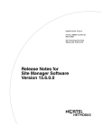
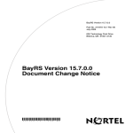
Figure 3-1 shows the default connection policy, status word 0xFF65.
Bit 15
Bit 0
1 1 1 1 1 1 1 1 0 1 1 0 0 1 0 1
Represents 0xFF65
Accept A-B
Accept A-M
Accept B-A
Accept B-M
LS0001A
Figure 3-1.
Default Connection Policy Status Word
Using the BCC
To set the SMT Connection Policy, access an existing FDDI line service and enter:
reject-policy <legal_value>
legal_value is any of the values listed in Table 3-2.
3-10
305259-A Rev 00
Configuring FDDI Services
For example, to set the SMT connection policy, enter the following command
sequence:
box# fddi slot 11 connector 1
fddi/11/1# reject-policy a-a
Using Site Manager
To set the SMT connection policy, complete the following tasks:
Site Manager Procedure
You do this
System responds
1. In the Configuration Manager window,
choose a FDDI Connector.
The Edit Connector window opens.
2. Choose Edit Line.
The Edit FDDI Parameters window
opens.
3. Choose Expert.
The FDDI Advanced Attributes window
opens.
4. Choose SMT Attributes.
The FDDI SMT Attributes window opens.
5. Set the Connection Policy parameter.
Click on Help or see the parameter
description on page A-8.
6. Click on OK.
You return to the FDDI Advanced
Attributes window.
7. Click on Done.
You return to the Edit Connector window.
8. Click on Done.
You return to the Configuration Manager
window.
Specifying the Neighbor Notification Interval
Neighbor information frames (NIFs) identify the upstream and downstream
neighbors of each node. A Bay Networks station issues a response to the sender of
a NIF frame and generates NIF requests as part of the neighbor notification
process.
You can set the interval between successful iterations of the Neighbor Notification
Protocol on an interface to a value from 2 to 30 seconds. By default, the interval is
22 seconds. This interval:
•
305259-A Rev 00
Determines the MAC addresses of the upstream and downstream neighbors
3-11
Configuring Ethernet, FDDI, and Token Ring Services
•
Detects duplicate MAC addresses on the ring
•
Generates periodic “keepalive” traffic that verifies the local MAC transmit
and receive paths
Using the BCC
To set the neighbor notification interval, access an existing FDDI line service and
enter:
neighbor-notify-time <integer>
integer is the neighbor notification interval value expressed in seconds. You can
enter any integer value from 2 to 30.
For example, to set the neighbor notification interval to 10, enter the following
command sequence:
box# fddi slot 11 connector 1
fddi/11/1# neighbor-notify-time 10
Using Site Manager
To set the neighbor notification interval, complete the following tasks:
Site Manager Procedure
You do this
System responds
1. In the Configuration Manager window,
choose a FDDI Connector.
The Edit Connector window opens.
2. Choose Edit Line.
The Edit FDDI Parameters window
opens.
3. Choose Expert.
The FDDI Advanced Attributes window
opens.
4. Choose SMT Attributes.
The FDDI SMT Attributes window opens.
5. Set the T_Notify Timeout parameter.
Click on Help or see the parameter
description on page A-8.
3-12
6. Click on OK.
You return to the FDDI Advanced
Attributes window.
7. Click on Done.
You return to the Edit Connector window.
8. Click on Done.
You return to the Configuration Manager
window.
305259-A Rev 00
Configuring FDDI Services
Specifying the Propagation Expiration Time
A trace is a diagnostic function that isolates a fault on the ring. By default, the
maximum propagation time for a trace on a FDDI topology is 7 seconds. You can
set the propagation expiration time to a value from 6001 to 256000 milliseconds
(ms).
Using the BCC
To set the propagation expiration time, access an existing FDDI line service and
enter:
token-rotation-time <integer>
integer is the propagation expiration time expressed in seconds.
For example, to set the propagation expiration time to 10, enter the following
command sequence:
box# fddi slot 11 connector 1
fddi/11/1# token-rotation-time 10
Using Site Manager
To set the propagation expiration time, complete the following tasks:
Site Manager Procedure
You do this
System responds
1. In the Configuration Manager window,
choose a FDDI Connector.
The Edit Connector window opens.
2. Choose Edit Line.
The Edit FDDI Parameters window
opens.
3. Choose Expert.
The FDDI Advanced Attributes window
opens.
4. Choose SMT Attributes.
The FDDI SMT Attributes window opens.
5. Set the Trace Max Expiration (ms)
parameter. Click on Help or see the
parameter description on page A-9.
6. Click on OK.
You return to the FDDI Advanced
Attributes window.
(continued)
305259-A Rev 00
3-13
Configuring Ethernet, FDDI, and Token Ring Services
Site Manager Procedure (continued)
You do this
System responds
7. Click on Done.
You return to the Edit Connector window.
8. Click on Done.
You return to the Configuration Manager
window.
Enabling or Disabling Status Report Frames
Status report frames (SRFs) allow the Status Report protocol to report node
conditions and events. A condition occurs when a node enters a specific state (for
example, duplicate address detected). An event is an immediate occurrence (for
example, the generation of a trace).
By default, the FDDI line generates an SRF announcement frame for its
implemented events (for example, high bit errors, topology changes, trace status
events, MAC frame error condition, and MAC duplicate address condition).
Bay Networks recommends enabling SRFs to ensure that your FDDI network is
ANSI-compliant.
To disable or reenable SRFs for this circuit, complete the following tasks:
Site Manager Procedure
You do this
System responds
1. In the Configuration Manager window,
choose a FDDI Connector.
The Edit Connector window opens.
2. Choose Edit Line.
The Edit FDDI Parameters window
opens.
3. Choose Expert.
The FDDI Advanced Attributes window
opens.
4. Choose SMT Attributes.
The FDDI SMT Attributes window opens.
5. Set the Status Report Protocol
parameter. Click on Help or see the
parameter description on page A-9.
6. Click on OK.
You return to the FDDI Advanced
Attributes window.
(continued)
3-14
305259-A Rev 00
Configuring FDDI Services
Site Manager Procedure (continued)
You do this
System responds
7. Click on Done.
You return to the Edit Connector window.
8. Click on Done.
You return to the Configuration Manager
window.
Enabling or Disabling Duplicate Addressing
By default, the router implements an optional ANSI duplicate address test
involving periodic transmission of Network Service Address Network Interface
Function (NSA NIF) frames to the source.
You can disable or enable duplicate addressing on an interface.
Using the BCC
To enable duplicate addressing on an interface, access an existing FDDI line
service and enter:
promiscuous enable
To disable duplicate addressing on an interface, access an existing FDDI line
service and enter:
promiscuous disable
For example, to enable duplicate addressing, enter the following command
sequence:
box# fddi slot 11 connector 1
fddi/11/1# promiscuous enable
305259-A Rev 00
3-15
Configuring Ethernet, FDDI, and Token Ring Services
Using Site Manager
To disable or reenable duplicate addressing on an interface, complete the
following tasks:
Site Manager Procedure
You do this
System responds
1. In the Configuration Manager window,
choose a FDDI Connector.
The Edit Connector window opens.
2. Choose Edit Line.
The Edit FDDI Parameters window
opens.
3. Choose Expert.
The FDDI Advanced Attributes window
opens.
4. Choose SMT Attributes.
The FDDI SMT Attributes window opens.
5. Set the Duplicate Address Protocol
parameter. Click on Help or see the
parameter description on page A-10.
3-16
6. Click on OK.
You return to the FDDI Advanced
Attributes window.
7. Click on Done.
You return to the Edit Connector window.
8. Click on Done.
You return to the Configuration Manager
window.
305259-A Rev 00
Configuring FDDI Services
Entering User Data
You can enter up to 32 alphanumeric characters of site-specific information to be
attached to the status information frames (SIFs) on this interface.
To enter information to be attached to the SIFs on this interface, complete the
following tasks:
Site Manager Procedure
You do this
System responds
1. In the Configuration Manager window,
choose a FDDI Connector.
The Edit Connector window opens.
2. Choose Edit Line.
The Edit FDDI Parameters window
opens.
3. Choose Expert.
The FDDI Advanced Attributes window
opens.
4. Choose SMT Attributes.
The FDDI SMT Attributes window opens.
5. Set the User Data parameter. Click on
Help or see the parameter description on
page A-9.
305259-A Rev 00
6. Click on OK.
You return to the FDDI Advanced
Attributes window.
7. Click on Done.
You return to the Edit Connector window.
8. Click on Done.
You return to the Configuration Manager
window.
3-17
Configuring Ethernet, FDDI, and Token Ring Services
Editing the MAC LLC Attributes
The FDDI media access control (MAC) standard defines the timed-token protocol,
frame and token construction and transmission on the FDDI ring, ring
initialization, and fault isolation.
Enabling or Disabling MAC LLC
When the ring becomes operational, the FDDI interface exchanges Logical Link
Control (LLC) protocol data units (PDUs) between the MAC and the local LLC
entity. You can enable or disable transmission of PDUs on an interface only by
using Site Manager.
Note: Enabling or disabling transmission of PDUs does not affect transferring
and receiving MAC or SMT frame types.
To disable or reenable transmission of PDUs on an interface, complete the
following tasks:
Site Manager Procedure
You do this
System responds
1. In the Configuration Manager window,
choose a FDDI Connector.
The Edit Connector window opens.
2. Choose Edit Line.
The Edit FDDI Parameters window
opens.
3. Choose Expert.
The FDDI Advanced Attributes window
opens.
4. Choose MAC Attributes.
The FDDI MAC Attributes window opens.
5. Set the LLC Data Enable parameter. Click
on Help or see the parameter description
on page A-10.
3-18
6. Click on OK.
You return to the FDDI Advanced
Attributes window.
7. Click on Done.
You return to the Edit Connector window.
8. Click on Done.
You return to the Configuration Manager
window.
305259-A Rev 00
Configuring FDDI Services
Editing FDDI Path Attributes
FDDI nodes exchange frames using the Timed-Token Protocol (TTP). The TTP
defines how the token target rotation time (TTRT) is set, the length of time a node
can hold the token, and how a node initializes the ring.
Each node is responsible for monitoring the integrity of the ring. By using a
minimum valid transmission timer (TVX), nodes can detect a break in ring
activity. If the interval between token receptions exceeds the value of the TVX, the
node reports an error condition and initiates the claim process to restore ring
operation.
The TTRT carried in claim frames issued by the FDDI station are known as path
attributes. Figure 3-2 illustrates their relationship.
TVX
lower
bound
0 ms
Requested TTRT
T_Max lower bound
2.5 ms
1336.9344 ms
LS0015A
Figure 3-2.
Range of Values for FDDI Path Attributes
You can set FDDI path attributes by:
305259-A Rev 00
•
Specifying the minimum TVX
•
Specifying the maximum TTRT
•
Specifying the requested TTRT
3-19
Configuring Ethernet, FDDI, and Token Ring Services
Specifying the Minimum TVX
The minimum TVX must be:
•
Greater than 0
•
Less than the requested TTRT value
By default, the minimum TVX is 2.5 ms. See Figure 3-2 on page 3-19 for the
range of values for TVX lower bound, in relation to the other TTRT parameters.
To set the minimum TVX, complete the following tasks:
Site Manager Procedure
You do this
System responds
1. In the Configuration Manager window,
choose a FDDI Connector.
The Edit Connector window opens.
2. Choose Edit Line.
The Edit FDDI Parameters window
opens.
3. Choose Expert.
The FDDI Advanced Attributes window
opens.
4. Choose Path Attributes.
The FDDI Path Attributes window opens.
5. Set the Tvx Lower Bound (ms)
parameter. Click on Help or see the
parameter description on page A-11.
3-20
6. Click on OK.
You return to the FDDI Advanced
Attributes window.
7. Click on Done.
You return to the Edit Connector window.
8. Click on Done.
You return to the Configuration Manager
window.
305259-A Rev 00
Configuring FDDI Services
Specifying the Maximum TTRT
The maximum TTRT value must be:
•
Greater than or equal to 10 ms
•
Greater than or equal to the value of the requested TTRT
•
Less than or equal to 1336.9344 ms
See Figure 3-2 on page 3-19 for the range of values for the maximum TTRT, in
relation to the other TTRT values.
To set the maximum TTRT value, complete the following tasks:
Site Manager Procedure
You do this
System responds
1. In the Configuration Manager window,
choose a FDDI Connector.
The Edit Connector window opens.
2. Choose Edit Line.
The Edit FDDI Parameters window
opens.
3. Choose Expert.
The FDDI Advanced Attributes window
opens.
4. Choose Path Attributes.
The FDDI Path Attributes window opens.
5. Set the T_Max Lower Bound (ms)
parameter. Click on Help or see the
parameter description on page A-11.
305259-A Rev 00
6. Click on OK.
You return to the FDDI Advanced
Attributes window.
7. Click on Done.
You return to the Edit Connector window.
8. Click on Done.
You return to the Configuration Manager
window.
3-21
Configuring Ethernet, FDDI, and Token Ring Services
Specifying the Requested TTRT
The requested TTRT value must be:
•
•
Greater than the minimum TVX
Less than or equal to the maximum TTRT
Caution: Be extremely careful when editing FDDI path parameters such as
Requested TTRT. Change the default values only if the network is part of a
production or other specialized environment that requires customizing the
parameters.
Refer to Figure 3-2 on page 3-19 for the valid range of values for requested TTRT,
in relation to the other TTRT values.
To set the requested TTRT value, complete the following tasks:
Site Manager Procedure
You do this
System responds
1. In the Configuration Manager window,
choose a FDDI Connector.
The Edit Connector window opens.
2. Choose Edit Line.
The Edit FDDI Parameters window
opens.
3. Choose Expert.
The FDDI Advanced Attributes window
opens.
4. Choose Path Attributes.
The FDDI Path Attributes window opens.
5. Set the Requested TTRT (ms) parameter.
Click on Help or see the parameter
description on page A-12.
3-22
6. Click on OK.
You return to the FDDI Advanced
Attributes window.
7. Click on Done.
You return to the Edit Connector window.
8. Click on Done.
You return to the Configuration Manager
window.
305259-A Rev 00
Configuring FDDI Services
Editing FDDI Port Attributes
Port attributes report the connection capabilities of a FDDI port, including the link
error rate (LER).
A status report frame (SRF) can contain link error monitoring (LEM) status
indicating the number of times that a link has been rejected. This is used to keep
track of the link error rate (LER).
You can configure the LER by:
•
Specifying the LER cutoff
•
Specifying the LER alarm rate
Specifying the LER Cutoff
The LER cutoff is an estimate at which a link connection will be broken. The LER
cutoff ranges from 10-4 to 101-5 and is reported as the absolute value of the base 10
logarithm. By default, the LER cutoff is 10-7.
To set the LER cutoff, complete the following tasks:
Site Manager Procedure
You do this
System responds
1. In the Configuration Manager window,
choose a FDDI Connector.
The Edit Connector window opens.
2. Choose Edit Line.
The Edit FDDI Parameters window
opens.
3. Choose Expert.
The FDDI Advanced Attributes window
opens.
4. Choose Port Attributes.
The FDDI Port Attributes window opens.
5. Set the LER Cutoff parameter. Click on
Help or see the parameter description on
page A-12.
305259-A Rev 00
6. Click on OK.
You return to the FDDI Advanced
Attributes window.
7. Click on Done.
You return to the Edit Connector window.
8. Click on Done.
You return to the Configuration Manager
window.
3-23
Configuring Ethernet, FDDI, and Token Ring Services
Specifying the LER Alarm Rate
The LER alarm rate is an estimate at which a link connection generates an alarm.
The LER alarm ranges from 10-4 to 10 -15 and is reported as the absolute value of
the base 10 logarithm of the estimate. By default, the LER alarm is 10-8.
To set the LER alarm rate, complete the following tasks:
Site Manager Procedure
You do this
System responds
1. In the Configuration Manager window,
choose a FDDI Connector.
The Edit Connector window opens.
2. Choose Edit Line.
The Edit FDDI Parameters window
opens.
3. Choose Expert.
The FDDI Advanced Attributes window
opens.
4. Choose Port Attributes.
The FDDI Port Attributes window opens.
5. Set the LER Alarm parameter. Click on
Help or see the parameter description on
page A-12.
3-24
6. Click on OK.
You return to the FDDI Advanced
Attributes window.
7. Click on Done.
You return to the Edit Connector window.
8. Click on Done.
You return to the Configuration Manager
window.
305259-A Rev 00
Configuring FDDI Services
Setting the Transmit Queue Length
The transmit queue length determines the number of buffers that can be used to
transmit data. Set the value from 0 to 255 to determine the transmit queue length.
If you set the value larger than the compiled ring size, the router will truncate the
value at that size.
To set the transmit queue length, access an existing FDDI line service and enter:
transmit-queue-length <integer>
integer is a value from 0 to 255.
For example, to set the transmit queue length to 100, enter the following command
sequence:
box# fddi slot 11 connector 1
fddi/11/1# transmit-queue-length 100
Setting the Receive Queue Length
The receive queue length determines the number of buffers that can be used to
receive data. Set the value from 0 to 255 to determine the receive queue length. If
you set the value larger than the compiled ring size, the router will truncate the
value at that size.
To set the receive queue length, access an existing FDDI line service and enter:
receive-queue-length <integer>
integer is a value from 0 to 255.
For example, to set the receive queue length to 100, enter the following command
sequence:
box# fddi slot 11 connector 1
fddi/11/1# receive-queue-length 100
305259-A Rev 00
3-25
Chapter 4
Configuring Token Ring Services
This chapter describes how to customize the physical and link layers for token
ring interfaces. It includes the following information:
305259-A Rev 00
Topic
Page
Configuring Token Ring Services Using the BCC or Site Manager
4-2
About Bay Networks Token Ring Media
4-2
Enabling or Disabling a Token Ring Interface
4-3
Specifying a MAC Address Override
4-4
Specifying a MAC Address Source
4-5
Specifying the Ring Speed
4-6
Enabling or Disabling Early Token Release
4-7
4-1
Configuring Ethernet, FDDI, and Token Ring Services
Configuring Token Ring Services Using the BCC or
Site Manager
Table 4-1 lists the token ring configuration tasks described in this chapter and
indicates whether you can use the BCC or Site Manager to perform each task.
Table 4-1.
Token Ring Configuration Tasks
Task
BCC
Site Manager
Enabling or Disabling a Token Ring Interface
✓
✓
Specifying a MAC Address Override
✓
Specifying a MAC Address Source
✓
Specifying the Ring Speed
Enabling or Disabling Early Token Release
✓
✓
✓
About Bay Networks Token Ring Media
Token ring is a 4 or 16 Mb/s token-passing, baseband LAN that operates in a ring
topology that conforms to the IEEE 802.5 standard. It is compatible with
IEEE 802.2 Type 1 (connectionless) and Type 2 (connection-oriented) support.
A token ring LAN uses shielded or unshielded twisted pair cable; the interface
supports IBM Type 1 and Type 3 cabling.
4-2
305259-A Rev 00
Configuring Token Ring Services
Enabling or Disabling a Token Ring Interface
The router enables token ring line services when you add the circuit. You can
disable and enable the interface without moving physical cabling.
Using the BCC
To enable token ring line services, access an existing token ring line service and
enter:
enable
To disable token ring line services, access an existing token ring line service and
enter:
disable
For example, to enable a token ring interface, enter the following command
sequence:
box# tokenring slot 9 connector 1
tokenring/9/1# enable
Using Site Manager
To enable or disable a token ring interface, complete the following tasks:
Site Manager Procedure
You do this
System responds
1. In the Configuration Manager window,
choose a TOKEN Connector.
The Edit Connector window opens.
2. Choose Edit Line.
The Edit Token Ring Parameters window
opens.
3. Set the Enable parameter. Click on Help
or see the parameter description on page
page A-13.
305259-A Rev 00
4. Click on OK.
You return to the Edit Connector window.
5. Click on Done.
You return to the Configuration Manager
window.
4-3
Configuring Ethernet, FDDI, and Token Ring Services
Specifying a MAC Address Override
To specify a MAC address for an interface (for example, to avoid host number
conflicts on a directly connected IPX or XNS network), enter the 48-bit MAC
address in MSB format; that is, enter 0x followed by 12 hexadecimal digits.
If you want the router to generate the MAC address for this token ring interface,
do not change this parameter from its default value of 0.
If you enter a MAC address with this parameter, you must set the MAC Address
Source to CNFG, as described in “Specifying a MAC Address Source,” on
page 4-5.
To specify a MAC address override, complete the following tasks:
Site Manager Procedure
You do this
System responds
1. In the Configuration Manager window,
choose a TOKEN Connector.
The Edit Connector window opens.
2. Choose Edit Line.
The Edit Token Ring Parameters window
opens.
3. Set the MAC Address Override
parameter. Click on Help or see the
parameter description on page A-13.
4-4
4. Click on OK.
You return to the Edit Connector window.
5. Click on Done.
You return to the Configuration Manager
window.
305259-A Rev 00
Configuring Token Ring Services
Specifying a MAC Address Source
By default, the token ring interface uses the MAC address stored in the
programmable read-only memory (PROM) on the link module.
You can set the source for MAC addresses on a token ring interface to:
•
BOXWIDE -- The interface uses a MAC address that the software generates
from the router’s serial number.
•
PROM -- The interface uses a MAC address from the PROM on the token ring
link module.
•
CNFG -- You explicitly assign a MAC address with the MAC Address
Override parameter.
To set the source for MAC addresses, complete the following tasks:
Site Manager Procedure
You do this
System responds
1. In the Configuration Manager window,
choose a TOKEN Connector.
The Edit Connector window opens.
2. Choose Edit Line.
The Edit Token Ring Parameters window
opens.
3. Set the MAC Address Select parameter.
Click on Help or see the parameter
description on page A-14.
305259-A Rev 00
4. Click on OK.
You return to the Edit Connector window.
5. Click on Done.
You return to the Configuration Manager
window.
4-5
Configuring Ethernet, FDDI, and Token Ring Services
Specifying the Ring Speed
You can set the ring speed for a token ring interface to 4 or 16 Mb/s. By default,
the ring speed is 16 Mb/s.
If you use 16 Mb/s, the router enables the early token release protocol, which is
used extensively on 16 Mb/s media. In the unlikely event that you want to disable
early token release over 16 Mb/s token ring media, disable early token release as
described in the next section.
Using the BCC
To set the ring speed for a token ring interface, access an existing token ring line
service and enter:
speed <value>
value is either 4 or 16.
For example, to set the ring speed to 16 Mb/s, enter the following command
sequence:
box# tokenring slot 9 connector 1
tokenring/9/1# speed 16
Using Site Manager
To set the ring speed, complete the following tasks:
Site Manager Procedure
You do this
System responds
1. In the Configuration Manager window,
choose a TOKEN Connector.
The Edit Connector window opens.
2. Choose Edit Line.
The Edit Token Ring Parameters window
opens.
3. Set the Speed parameter. Click on Help or
see the parameter description on
page A-14.
4-6
4. Click on OK.
You return to the Edit Connector window.
5. Click on Done.
You return to the Configuration Manager
window.
305259-A Rev 00
Configuring Token Ring Services
Enabling or Disabling Early Token Release
Early token release indicates that the token can return to the ring before the
recipient copies all data. By default, Site Manager enables early token release on
an interface.
You can disable or enable early token release on an interface only when the ring
speed is 16 Mb/s.
To enable or disable early token release, complete the following tasks:
Site Manager Procedure
You do this
System responds
1. In the Configuration Manager window,
choose a TOKEN Connector.
The Edit Connector window opens.
2. Choose Edit Line.
The Edit Token Ring Parameters window
opens.
3. Set the Early Token Release parameter.
Click on Help or see the parameter
description on page A-15.
305259-A Rev 00
4. Click on OK.
You return to the Edit Connector window.
5. Click on Done.
You return to the Configuration Manager
window.
4-7
Chapter 5
Configuring 802.1Q Tagging
This chapter provides an overview of 802.1Q tagging and instructions for
configuring it on a router. It includes the following information:
Topic
Page
Virtual LAN Overview
5-1
802.1Q Tagging
5-6
Router Processing of Tagged Frames
5-7
Implementation Considerations
5-8
Adding a Tagged Circuit to an Unconfigured 100BASE-T Interface
5-8
Adding a Tagged Circuit to an Existing 100BASE-T Interface
5-10
Editing a Tagged Circuit
5-11
Disabling a Tagged Circuit
5-12
Deleting a Tagged Circuit
5-12
Virtual LAN Overview
Traditional LANs are defined by physical media:
•
Early first-generation LANs were defined by the cable or fiber that connected
workstations.
•
Later second-generation LANs, or LAN segments, are defined by the
concentrators, repeaters, or hubs (all physical layer, or layer 1, devices) that
connect workstations.
Traditional LANs are connected by bridges at layer 2 or by routers at layer 3.
305259-A Rev 00
5-1
Configuring Ethernet, FDDI, and Token Ring Services
Modern, intelligent switching devices have enabled the construction and
interconnection of virtual LANs (VLANs). The term VLAN is generally
understood to mean the following:
•
A VLAN is a flexible, software-defined logical group of devices; VLAN
boundaries are independent of the physical media.
Figure 5-1 shows a second-generation network topology with a bridge
connecting four LANs or LAN segments, and the same physical topology
with an intelligent switching device (such as one of the Accelar™ family of
routing switches) providing connectivity.
Hub
Hub
LAN
Segment 1
LAN Segment 1
Engineering
VLAN
Hub
Hub
LAN
Segment 2
Hub
LAN
Segment 2
Hub
LAN
Segment 3
LAN
Segment 3
Marketing
VLAN
Hub
Hub
LAN
Segment 4
LAN
Segment 4
Bridge
VLAN device
SN0007A
Figure 5-1.
VLAN Topology
As illustrated in Figure 5-1, the four VLAN segments can be reconfigured as
two VLANs: the Engineering VLAN, consisting of LAN segments 1 and 2,
and the Marketing VLAN, consisting of LAN segments 3 and 4.
5-2
305259-A Rev 00
Configuring 802.1Q Tagging
•
A VLAN contains broadcast traffic within software-defined boundaries.
With reference to Figure 5-1, broadcast traffic within the bridged topology is
propagated across all physical interfaces. For example, a broadcast frame
originated by a workstation on LAN segment 1 is forwarded to LAN segments
2, 3, and 4. In contrast, within the VLAN topology, a broadcast frame
originated by a workstation on LAN segment 1 is forwarded only to LAN
segment 2. Broadcast traffic is confined with the bounds of the VLAN.
•
A VLAN provides low-latency, wire-speed communication between VLAN
members.
All members of the Engineering VLAN, for example, communicate at wire
speed whether they are physically connected to LAN segment 1 or 2.
•
A VLAN supports network segmentation or microsegmentation; a VLAN
segment can consist of one or many workstations.
•
A VLAN is a closed bridge group, with boundaries enforced by spanning tree
protocols.
•
Intra-VLAN communication is provided by layer 2 switching.
•
Inter-VLAN communication requires additional layer 3 services. Layer 3
services may be provided by the VLAN device or by an adjacent router.
Intra-VLAN Traffic Flow
Intra-VLAN traffic (where the frame source and the frame destination are both on
the same VLAN) is forwarded at layer 2 by the VLAN device. Forwarding
decisions are based on layer 2 forwarding tables that associate specific MAC/layer
2 addresses with specific device ports.
Inter-VLAN Traffic Flow
Inter-VLAN traffic (where the frame source and the frame destination are not on
the same VLAN) requires layer 3 (routing) services. Certain advanced platforms
(such as the Accelar family of routing switches) can provide these services.
305259-A Rev 00
5-3
Configuring Ethernet, FDDI, and Token Ring Services
More commonly, however, routing services are provided by an adjacent router, as
shown in Figure 5-2, where frames originating on the Marketing VLAN and
destined for the Sales VLAN are switched across a dedicated port by the VLAN
device to the attached router. The router, operating at layer 3, redirects the frame
across another dedicated port to the VLAN device, which in turns switches the
frame at layer 2 to the recipient VLAN.
The configuration illustrated in Figure 5-2 is inefficient for both the router and the
VLAN device, because it requires a dedicated port for each VLAN. In network
topologies that support multiple VLANs, the costs for dedicated ports may be
prohibitive.
Engineering
IP VLAN
Marketing
IP VLAN
VLAN
device
Traffic flow
Dedicated VLAN-specific
untagged ports
Sales
IP VLAN
Router
SN0020A
Figure 5-2.
5-4
Connecting VLANs Using a Router
305259-A Rev 00
Configuring 802.1Q Tagging
In contrast, Figure 5-3 depicts a topology in which the same three VLANs share a
common connection to the adjacent router. This common connection is enabled by
a packet encapsulation format specified in IEEE 802.1Q, Draft Standard for
Virtual Bridged Local Area Networks. This packet encapsulation format is
referred to as 802.1Q tagging.
Engineering
IP VLAN
Marketing
IP VLAN
VLAN
device
Sales
all-protocol VLAN
Traffic flow
Single untagged port serves the
Marketing and Sales VLANs
Router
SN0021A
Figure 5-3.
305259-A Rev 00
Connecting VLANs Using 802.1Q Tagging
5-5
Configuring Ethernet, FDDI, and Token Ring Services
802.1Q Tagging
802.1Q tagging enables multiple VLANs to share a common connection to a
router. The router provides layer 3 routing services for the VLAN clients. The
router may provide standard routing services, that is, directing received frames
toward a remote destination; or it may function as a so-called “one-armed” router,
returning frames to the device from which it received them, but forwarding them
to a different logical entity.
Shared usage of a common physical port (often referred to as a tagged port) is
facilitated by the addition of two 2-byte fields within the standard Ethernet header
(Figure 5-4).
IEEE 802.1Q encapsulation
Ethernet encapsulation
Destination address
(6 octets)
Source address
(6 octets)
Destination address
(6 octets)
Source address
(6 octets)
Tag protocol identifier
(2 octets)
Protocol type
(2 octets)
Tag control information
(2 octets)
Data
(46 to 1496 octets)
Protocol type
(2 octets)
FCS
(4 octets)
Data
(46 to 1496 octets)
Maximum size: 1514 octets
FCS
(4 octets)
Maximum size: 1518 octets
SN0016A
Figure 5-4.
5-6
IEEE 802.1Q Tagging
305259-A Rev 00
Configuring 802.1Q Tagging
The IEEE has not yet standardized values for the tag protocol identifier (TPID)
field, leaving vendors to provide their own proprietary values. The Accelar family
of routing switches, for example, writes a value of 8100 (hexadecimal) to this
field.
The tag control information (TCI) field contains a unique value that identifies the
VLAN on which the frame originated. This value is assigned during the
configuration of the layer 2 device.
The addition of the four bytes required for the TPID and TCI fields raises the
possibility of generating frames up to 1518 bytes in length, four bytes larger than
the maximum packet size specified by Ethernet. Consequently, for frames on
which 802.1Q tagging is enabled, BayRS accepts such outsized frames.
Router Processing of Tagged Frames
802.1Q tagging is supported only on 100BASE-T interfaces that connect the Bay
Networks router to an 802.1Q-compliant switch or routing switch. With 802.1Q
tagging enabled, the physical connection between the router and the adjacent
device supports multiple virtual connections.
The number of connections is equal to the number of virtual connections plus a
default physical connection that provides transit services for other non-VLAN
traffic that may be received from or forwarded to the adjacent device.
Upon receipt of a frame across a virtual connection, a circuit manager strips the
four bytes of 802.1Q header information and directs a now standard Ethernet
frame to a connection-specific routing process. The routing process consults its
forwarding table and, in turn, directs the frame to a circuit manager handling the
next-hop connection. If that connection is a non-tagged, non-virtual connection,
processing is completed as for any other standard Ethernet frame.
However, if the next-hop connection is a tagged, virtual connection, the circuit
manager inserts the four bytes of 802.1Q header information that identify that
VLAN into the standard Ethernet header. After performing the 802.1Q
encapsulation, the circuit manager forwards the frame across the virtual
connection toward the destination VLAN.
305259-A Rev 00
5-7
Configuring Ethernet, FDDI, and Token Ring Services
Implementation Considerations
Before you configure 802.1Q tagging on a router, note the following
considerations:
•
802.1Q tagging is supported only on 100BASE-T interfaces; it is not
supported on other LAN interfaces.
•
802.1Q tagging cannot be used to extend a VLAN across multiple devices.
•
The VLAN type (port-based, protocol-based, address-based, and so on) is
ignored by the router.
Adding a Tagged Circuit to an Unconfigured 100BASE-T
Interface
The following procedure describes how to add an 802.1Q tagged circuit to a
previously unconfigured 100BASE-T interface. This procedure assumes that you
are configuring the 802.1Q tagged circuit for IP routing. To enable other routing
protocols on an 802.1Q tagged circuit, see the appropriate guide for that protocol.
Site Manager Procedure
You do this
System responds
1. In the Configuration Manager window,
click on a 100BASE-T connector.
The Add Circuit window opens.
2. Click on OK.
The Select Protocols window opens.
3. Choose VLAN, then click on OK.
The Edit VLAN Interface Parameters
window opens.
4. Click on Add.
The TAG1Q Parameters window opens.
5. Set the following parameters:
• VLAN Name
• Global VLAN Id
Click on Help or see the parameter
descriptions beginning on page A-15.
6. Click on OK.
The Edit VLAN Interface Parameters
window opens. Note that 802.1Q tagged
circuits are displayed with a V n extension.
(continued)
5-8
305259-A Rev 00
Configuring 802.1Q Tagging
Site Manager Procedure (continued)
You do this
System responds
7. Select the 802.1Q tagged circuit that you
are adding. Set the Protocol Type (hex)
parameter. Retain the default value for
connection to Bay Networks
802.1Q-enabled devices.
8. Click on Apply and Done.
You return to the Configuration Manager
window.
To add IP routing to the 802.1Q tagged circuit:
9. Choose Circuits.
10. Choose Edit Circuits.
The Circuit List window opens.
11. Select the 802.1Q tagged circuit.
Note that 802.1Q tagged circuits are
displayed with a Vn extension.
12. Click on Edit.
The Circuit Definition window opens.
13. Choose Protocols.
14. Choose Add/Delete.
The Select Protocols window opens.
15. Select IP and click on OK.
The IP Configuration window opens.
16. Enter an IP address and subnet mask and The Circuit Definition window opens.
click on OK.
17. Choose File.
305259-A Rev 00
18. Choose Exit.
The Circuit List window opens.
19. Click on Done.
You return to the Configuration Manager
window.
5-9
Configuring Ethernet, FDDI, and Token Ring Services
Adding a Tagged Circuit to an Existing 100BASE-T Interface
To add an 802.1Q tagged circuit to an existing 100BASE-T interface, complete
the following tasks:
Site Manager Procedure
You do this
System responds
1. In the Configuration Manager window,
click on a 100BASE-T connector.
The Edit Connector window opens.
2. Click on Edit Circuit.
The Circuit Definition window opens.
3. Choose Protocols.
The Protocols menu opens.
4. Choose Add/Delete.
The Select Protocols window opens.
5. Choose VLAN, then click on OK.
The Edit VLAN Interface Parameters
window opens.
6. Click on Add.
The TAG1Q Parameters window opens.
7. Set the following parameters:
• VLAN Name
• Global VLAN Id
Click on Help or see the parameter
descriptions beginning on page A-15.
8. Click on OK.
The Edit VLAN Interface Parameters
window opens. Note that 802.1Q tagged
circuits are displayed with a V n extension.
9. Select the 802.1Q tagged circuit that you
are adding. Set the Protocol Type (hex)
parameter. Retain the default value for
connection to Bay Networks
802.1Q-enabled devices.
10. Click on Apply and Done.
You return to the Configuration Manager
window.
To add IP routing to the 802.1Q tagged circuit:
11. Choose Circuits.
12. Choose Edit Circuits.
The Circuit List window opens.
13. Select the 802.1Q tagged circuit.
Note that 802.1Q tagged circuits are
displayed with a Vn extension.
(continued)
5-10
305259-A Rev 00
Configuring 802.1Q Tagging
Site Manager Procedure (continued)
You do this
System responds
14. Click on Edit.
The Circuit Definition window opens.
15. Choose Protocols.
16. Choose Add/Delete.
The Select Protocols window opens.
17. Select IP and click on OK.
The IP Configuration window opens.
18. Enter an IP address and subnet mask and The Circuit Definition window opens.
click on OK.
19. Choose File.
20. Choose Exit.
The Circuit List window opens.
21. Click on Done.
You return to the Configuration Manager
window.
Editing a Tagged Circuit
To edit an 802.1Q tagged circuit, complete the following tasks:
Site Manager Procedure
You do this
System responds
1. In the Configuration Manager window,
choose Protocols.
The Protocols menu opens.
2. Choose VLAN.
The VLAN menu opens.
3. Choose Interfaces.
The Edit VLAN Interface Parameters
window opens.
4. Select the 802.1Q tagged circuit that you
want to edit.
Site Manager displays the current
parameter values for the circuit.
5. Edit the following parameters as required:
• VLAN Name
• Global VLAN Id
• Protocol Type (hex)
Click on Help or see the parameter
descriptions beginning on page A-15.
6. Click on Apply and Done.
305259-A Rev 00
You return to the Configuration Manager
window.
5-11
Configuring Ethernet, FDDI, and Token Ring Services
Disabling a Tagged Circuit
To disable an 802.1Q tagged circuit, complete the following tasks:
Site Manager Procedure
You do this
System responds
1. In the Configuration Manager window,
choose Protocols.
The Protocols menu opens.
2. Choose VLAN.
The VLAN menu opens.
3. Choose Interfaces.
The Edit VLAN Interface Parameters
window opens.
4. Select the 802.1Q tagged circuit that you
want to disable.
Site Manager displays the current
parameter values for the circuit.
5. Set the Enable/Disable parameter to
Disable.
6. Click on Apply and Done.
You return to the Configuration Manager
window.
Deleting a Tagged Circuit
To delete an 802.1Q tagged circuit, complete the following tasks:
Site Manager Procedure
5-12
You do this
System responds
1. In the Configuration Manager window,
choose Protocols.
The Protocols menu opens.
2. Choose VLAN.
The VLAN menu opens.
3. Choose Interfaces.
The Edit VLAN Interface Parameters
window opens.
4. Select the 802.1Q tagged circuit that you
want to delete.
Site Manager displays the current
parameter values for the circuit.
5. Click on Delete and Done.
You return to the Configuration Manager
window.
305259-A Rev 00
Appendix A
Site Manager Parameters
This appendix contains the Site Manager parameter descriptions for Ethernet,
FDDI, and token ring line services and for 802.1Q tagging. You can display the
same information using Site Manager online Help.
This appendix contains the following information:
Topic
Page
CSMA/CD Line Parameters
A-2
FDDI Line Parameters
A-5
Token Ring Line Parameters
A-13
802.1Q Parameters
A-15
For each parameter, this appendix provides the following information:
•
•
•
•
•
•
•
305259-A Rev 00
Parameter name
Configuration Manager menu path
Default setting
Valid parameter options
Parameter function
Instructions for setting the parameter
Management information base (MIB) object ID
A-1
Configuring Ethernet, FDDI, and Token Ring Services
The Technician Interface allows you to modify parameters by issuing set and
commit commands with the MIB object ID. This process is equivalent to
modifying parameters using Site Manager. For more information about using the
Technician Interface to access the MIB, see Using Technician Interface Software.
Caution: The Technician Interface does not verify the validity of your
parameter values. Entering an invalid value can corrupt your configuration.
CSMA/CD Line Parameters
Parameter: Enable
Path: Configuration Manager > XCVR Connector > Edit Line > Edit CSMA/CD
Parameters
Default: Enable
Options: Enable | Disable
Function: Enables or disables this Ethernet line.
Instructions: Select Enable or Disable.
MIB Object ID: 1.3.6.1.4.1.18.3.4.1.1.2
Parameter: BofL Enable
Path: Configuration Manager > XCVR Connector > Edit Line > Edit CSMA/CD
Parameters
Default: Enable
Options: Enable | Disable
Function: When set to Enable, the router sends BofL polling messages from this system to
all systems on the local network.
Instructions: Set to Enable or Disable. We recommend that you enable BofL.
MIB Object ID: 1.3.6.1.4.1.18.3.4.1.1.7
A-2
305259-A Rev 00
Site Manager Parameters
Parameter: BofL Timeout
Path: Configuration Manager > XCVR Connector > Edit Line > Edit CSMA/CD
Parameters
Default: 5 (4 if router redundancy is enabled)
Options: 1 to 60 seconds
Function: Specifies the time between transmissions of Breath of Life messages from this
Ethernet interface. Timeout will occur if five periods elapse without a successful
BofL message transmission. When timeout occurs, the router disables and
reenables the Ethernet interface.
This parameter is valid only if you set BofL Enable to Enable.
Instructions: Accept the default BofL timeout of 5 seconds, or specify a new value up to 60
seconds.
MIB Object ID: 1.3.6.1.4.1.18.3.4.1.1.8
Parameter: Hardware Filter
Path: Configuration Manager > XCVR Connector (10BASE-T only) > Edit Line >
Edit CSMA/CD Parameters
Default: Disable (the default changes to Enable when, while adding the circuit, you reply
OK to the prompt:
Do you want to enable Hardware Filters on this circuit?)
Options: Enable | Disable
Function: Enables filtering hardware in the link or net module to drop local frames at the
interface instead of copying them into system memory. Enabling hardware
filters improves bridging software performance because router resources are not
used to receive and reject local frames.
Instructions: Set to Enable only if you enabled the bridge software and the link or net module
has hardware filters.
MIB Object ID: 1.3.6.1.4.1.18.3.4.1.1.29
305259-A Rev 00
A-3
Configuring Ethernet, FDDI, and Token Ring Services
Parameter: Interface Line Speed
Path: Configuration Manager > XCVR Connector (100BASE-T only) > Edit Line >
Edit CSMA/CD Parameters
Default: 100Base-TX/100Base-FX (for 100BASE-FX Ethernet modules);
Auto Negotiation (for 10/100BASE-TX Ethernet modules)
Options: Auto Negotiation | 10Base-T | 10Base-T (Full Duplex) |
100Base-TX/100Base-FX | 100Base-TX (Full Duplex)
Note: The options available depend on the module you are using.
Function: Specifies the configured line speed and duplex setting for the selected interface,
or enables automatic line negotiation.
Instructions: To enable automatic line negotiation, select Auto Negotiation.
To configure a specific line speed, select one of the following:
•
•
•
•
10Base-T
10Base-T (Full Duplex)
100Base-TX/100Base-FX
100Base-TX (Full Duplex)
Selecting a specific line-speed configuration disables Auto Negotiation.
MIB Object ID: 1.3.6.1.4.1.18.3.4.16.1.1.4
A-4
305259-A Rev 00
Site Manager Parameters
Parameter: Line Advertising Capabilities
Path: Configuration Manager > XCVR Connector (100BASE-T only) > Edit Line >
Edit CSMA/CD Parameters > Interface Line Speed parameter = Auto
Negotiation > OK > Configure Line Capabilities
Default: 1111
Options: 0000 | 1000 | 0100 | 0010 | 0001 | 1111
Function: Specifies the line configurations available to remote nodes that have automatic
line negotiation capability.
Instructions: Select the code for the desired line advertising:
• No advertising = 0000
• 10Base-T = 1000
• 10Base-T, full duplex only = 0100
• 100Base-TX = 0010
• 100Base-TX, full duplex only = 0001
• All advertising = 1111
MIB Object ID: 1.3.6.1.4.1.18.3.4.16.1.1.9
FDDI Line Parameters
Parameter: Enable
Path: Configuration Manager > FDDI Connector > Edit Line > Edit FDDI
Parameters
Default: Enable
Options: Enable | Disable
Function: Enables or disables the FDDI circuit for the selected connector.
Instructions: Set to Enable or Disable.
MIB Object ID: 1.3.6.1.4.1.18.3.4.4.1.2
305259-A Rev 00
A-5
Configuring Ethernet, FDDI, and Token Ring Services
Parameter: BofL Enable
Path: Configuration Manager > FDDI Connector > Edit Line > Edit FDDI
Parameters
Default: Enable
Options: Enable | Disable
Function: Enables or disables BofL polling.
When you set both this parameter and the LLC Data Enable parameter to
Enable, the router disables the LLC interface after the time you specify using
the BofL Timeout parameter if the link becomes unavailable.
When you set this parameter to Disable, the router disables the LLC interface
immediately after the link becomes unavailable.
Instructions: Set to Enable or Disable.
MIB Object ID: 1.3.6.1.4.1.18.3.4.4.1.7
Parameter: BofL Timeout
Path: Configuration Manager > FDDI Connector > Edit Line > Edit FDDI
Parameters
Default: 3
Options: 1 to 60 seconds
Function: When BofL is enabled and the link becomes unavailable, this parameter
specifies the time Site Manager waits before disabling the LLC interface.
Instructions: Accept the default value, 3 seconds, or specify a new value. Be sure to set the
BofL Enable parameter to Enable.
MIB Object ID: 1.3.6.1.4.1.18.3.4.4.1.8
A-6
305259-A Rev 00
Site Manager Parameters
Parameter: Hardware Filter
Path: Configuration Manager > FDDI Connector > Edit Line > Edit FDDI
Parameters
Default: Disable (the default changes to Enable when, while adding the circuit, you reply
OK to the prompt:
Do you want to enable Hardware Filters on this circuit?)
Options: Enable | Disable
Function: When you set this parameter to Enable, the link module filtering hardware, if
present, does not allow the router to copy local frames into memory. In essence,
the filtering hardware drops local frames at the interface. Hardware filtering
improves performance because the bridging software no longer uses resources
to receive and reject those frames.
Instructions: Set to Enable only if the link module has hardware filters and you enabled
bridge software.
MIB Object ID: 1.3.6.1.4.1.18.3.4.4.1.37
305259-A Rev 00
A-7
Configuring Ethernet, FDDI, and Token Ring Services
Parameter: Connection Policy
Path: Configuration Manager > FDDI Connector > Edit Line > Edit FDDI
Parameters > Expert > SMT Attributes > FDDI SMT Attributes
Default: 0xFF65
Options: 0x0 to 0xFFFF
Function: Specifies the connection policies this line requests at the FDDI station.
The policy descriptor takes the form “rejectX-Y” where X denotes the physical
connection (PC) type of the local port, and Y denotes the PC type of the
neighbor port. X and Y can have the following values:
• A -- Indicates that the port is a dual-attachment station or concentrator that
attaches to the primary IN and the secondary OUT when attaching to the dual
FDDI ring
• B -- Indicates that the port is a dual-attachment station or concentrator that
attaches to the secondary IN and the primary OUT when attaching to the dual
FDDI ring
• S -- Indicates a port in a single-attachment station or concentrator
• M -- Indicates a port in a concentrator that serves as a master to a connected
station or concentrator
Instructions: Specify the status word value that represents the connection policies you want
this line to reject. Start with a value of zero for the status word (all bits set to 0).
For each connection policy you want the node to reject, add to the status word
value the number 2 raised to a power specified in Table 3-2 on page 3-10. This
is equivalent to setting a bit to 1 for each policy that you want the node to reject.
MIB Object ID: 1.3.6.1.4.1.18.3.4.4.1.30
Parameter: T_Notify Timeout
Path: Configuration Manager > FDDI Connector > Edit Line > Edit FDDI
Parameters > Expert > SMT Attributes > FDDI SMT Attributes
Default: 22
Options: 2 to 30 seconds
Function: Specifies the interval between successful iterations of the Neighbor Notification
Protocol.
Instructions: Accept the default value of 22 seconds or specify a new value from 2 to 30
seconds.
MIB Object ID: 1.3.6.1.4.1.18.3.4.4.1.31
A-8
305259-A Rev 00
Site Manager Parameters
Parameter: User Data
Path: Configuration Manager > FDDI Connector > Edit Line > Edit FDDI
Parameters > Expert > SMT Attributes > FDDI SMT Attributes
Default: None
Options: Any string up to 32 alphanumeric characters
Function: Allows you to enter additional information about the router. This information is
attached to the status information frames (SIFs).
Instructions: Enter up to 32 alphanumeric characters.
MIB Object ID: 1.3.6.1.4.1.18.3.4.15.1.3.1.8
Parameter: Status Report Protocol
Path: Configuration Manager > FDDI Connector > Edit Line > Edit FDDI
Parameters > Expert > SMT Attributes > FDDI SMT Attributes
Default: Enable
Options: Enable | Disable
Function: Specifies whether the node will generate Status Report Frames (SRFs) for its
implemented events (for example, high bit errors, topology changes, trace status
events, MAC frame error condition, port LER condition, and MAC duplicate
address condition).
Instructions: Accept the default, Enable, if you want the node to generate SRFs; specify
Disable if you do not want the node to generate SRFs. We recommend using
Enable to ensure that your FDDI network is ANSI-compliant.
MIB Object ID: 1.3.6.1.4.1.18.3.4.15.1.3.1.14
Parameter: Trace Max Expiration (ms)
Path: Configuration Manager > FDDI Connector > Edit Line > Edit FDDI
Parameters > Expert > SMT Attributes > FDDI SMT Attributes
Default: 7000
Options: 6001 to 256000 milliseconds
Function: Specifies the maximum propagation time for a trace on an FDDI topology.
Instructions: Enter a value from 6001 to 256000. We recommend accepting the default value
of 7000 milliseconds (7 seconds).
MIB Object ID: 1.3.6.1.4.1.18.3.4.15.1.3.1.15
305259-A Rev 00
A-9
Configuring Ethernet, FDDI, and Token Ring Services
Parameter: Duplicate Address Protocol
Path: Configuration Manager > FDDI Connector > Edit Line > Edit FDDI
Parameters > Expert > SMT Attributes > FDDI SMT Attributes
Default: Enable
Options: Enable | Disable
Function: Implements an optional ANSI duplicate address test involving periodic
transmission of Network Service Address Network Interface Function (NSA
NIF) frames to the source.
Instructions: Accept the default, Enable, if you want to test for duplicate addresses. Specify
Disable if you do not want to test for duplicate addresses.
MIB Object ID: 1.3.6.1.4.1.18.3.4.15.1.3.1.18
Parameter: LLC Data Enable
Path: Configuration Manager > FDDI Connector > Edit Line > Edit FDDI
Parameters > Expert > MAC Attributes > FDDI MAC Attributes
Default: Enable
Options: Enable | Disable
Function: Specifies whether the MAC is available to transmit and receive Logical Link
Control (LLC) protocol data units (PDUs). If you accept Enable, the interface to
the MAC entity is available to exchange PDUs between the MAC and the local
LLC entity when the ring becomes operational. Setting this attribute does not
affect transferring and receiving MAC or SMT frame types.
Instructions: Accept the default, Enable, if you want the MAC available for transmitting and
receiving LLC PDUs; specify Disable if you do not want the MAC available for
transmitting and receiving LLC PDUs.
MIB Object ID: 1.3.6.1.4.1.18.3.4.15.2.3.1.17
A-10
305259-A Rev 00
Site Manager Parameters
Parameter: Tvx Lower Bound (ms)
Path: Configuration Manager > FDDI Connector > Edit Line > Edit FDDI
Parameters > Expert > Path Attributes > FDDI Path Attributes
Default: 2.5
Options: The value (in milliseconds) must be greater than zero and less than the value of
Requested TTRT. If the value of Requested TTRT is greater than 5.2 ms, set this
parameter to a value less than or equal to 5.2 ms. For example, if the value of
Requested TTRT is 165 ms, the value for Tvx Lower Bound must be less than or
equal to 5.2 ms.
Function: Specifies the minimum time value of the Valid Transmission Timer (TVX).
Instructions: Accept the default value of 2.5 milliseconds or specify a new value less than or
equal to 5.2 milliseconds and less than the value of Requested TTRT.
MIB Object ID: 1.3.6.1.4.1.18.3.4.15.3.3.1.5
Parameter: T_Max Lower Bound (ms)
Path: Configuration Manager > FDDI Connector > Edit Line > Edit FDDI
Parameters > Expert > Path Attributes > FDDI Path Attributes
Default: 165
Options: 10 to 1336.9344 ms
Function: Allows you to specify the maximum time value of TTRT. The value (in
milliseconds) must be greater than or equal to 10 ms, greater than or equal to the
value of the Requested TTRT (ms) parameter, and less than or equal to
1336.9344 ms.
Instructions: Accept the default value of 165 ms, or specify a new value less than or equal to
1336.9344 ms and greater than or equal to the value of the Requested TTRT
(ms) parameter.
MIB Object ID: 1.3.6.1.4.1.18.3.4.15.3.3.1.6
305259-A Rev 00
A-11
Configuring Ethernet, FDDI, and Token Ring Services
Parameter: Requested TTRT (ms)
Path: Configuration Manager > FDDI Connector > Edit Line > Edit FDDI
Parameters > Expert > Path Attributes > FDDI Path Attributes
Default: 165
Options: Variable. This value (in milliseconds) must be greater than the value specified
for the TVX Lower Bound (ms) parameter and less than or equal to the value
specified for the T_Max Lower Bound (ms) parameter.
Function: Specifies the target token rotation time carried in claim frames issued by the
FDDI station.
Instructions: Accept the default of 165 ms or enter a new value in milliseconds.
MIB Object ID: 1.3.6.1.4.1.18.3.4.4.1.32
Parameter: LER Cutoff
Path: Configuration Manager > FDDI Connector > Edit Line > Edit FDDI
Parameters > Expert > Port Attributes > FDDI Port Attributes
Default: 7
Options: 4 to 15
Function: Specifies the link error rate estimate at which a link connection is broken. It
ranges from 10-4 to 10-15 and is reported as the absolute value of the base 10
logarithm.
Instructions: Accept the default value of 7 or specify a new value.
MIB Object ID: 1.3.6.1.4.1.18.3.4.15.4.3.1.17
Parameter: LER Alarm
Path: Configuration Manager > FDDI Connector > Edit Line > Edit FDDI
Parameters > Expert > Port Attributes > FDDI Port Attributes
Default: 8
Options: 4 to 15
Function: Specifies the link error rate estimate at which a link connection generates an
alarm. It ranges from 10-4 to 10-15 and is reported as the absolute value of the
base 10 logarithm of the estimate.
Instructions: Accept the default value of 8 or specify a new value.
MIB Object ID: 1.3.6.1.4.1.18.3.4.15.4.3.1.18
A-12
305259-A Rev 00
Site Manager Parameters
Token Ring Line Parameters
Parameter: Enable
Path: Configuration Manager > TOKEN Connector > Edit Line > Edit Token Ring
Parameters
Default: Enable
Options: Enable | Disable
Function: Enables or disables the token ring circuit.
Instructions: Set to Disable if you want to disable the token ring circuit.
MIB Object ID: 1.3.6.1.4.1.18.3.4.2.1.2
Parameter: MAC Address Override
Path: Configuration Manager > TOKEN Connector > Edit Line > Edit Token Ring
Parameters
Default: None
Options: Any valid, 48-bit MAC-level address
Function: Assigns a user-specified MAC address.
Instructions: If you want the router to generate the MAC address for this token ring interface,
ignore this parameter.
If you want to specify a MAC address (for example, to avoid host number
conflicts on a directly connected IPX or XNS network), enter the 48-bit MAC
address in MSB format; that is, enter 0x followed by 12 hexadecimal digits.
If you enter a MAC address with this parameter, you must set the MAC Address
Select parameter to CNFG.
MIB Object ID: 1.3.6.1.4.1.18.3.4.2.1.9
305259-A Rev 00
A-13
Configuring Ethernet, FDDI, and Token Ring Services
Parameter: MAC Address Select
Path: Configuration Manager > TOKEN Connector > Edit Line > Edit Token Ring
Parameters
Default: PROM
Options: BOXWIDE | PROM | CNFG
Function: Determines the source of the MAC address.
Instructions: Enter BOXWIDE if you want the token ring interface to use a MAC address that
the software generates from the router’s serial number.
Enter PROM if you want the token ring interface to use a MAC address from
programmable read-only memory on the token ring link module.
Enter CNFG if you explicitly assigned a MAC address with the MAC Address
Override parameter.
MIB Object ID: 1.3.6.1.4.1.18.3.4.2.1.10
Parameter: Speed
Path: Configuration Manager > TOKEN Connector > Edit Line > Edit Token Ring
Parameters
Default: 16
Options: 16 Mb/s | 4 Mb/s
Function: Specifies the speed of the token ring media. If you select 16 Mb/s, the router
enables the Early Token Release protocol, which is used extensively on 16 Mb/s
media. In the unlikely event that you want to disable early token release over
16 Mb/s token ring media, you can do so with the Early Token Release
parameter.
Instructions: Enter the ring speed.
MIB Object ID: 1.3.6.1.4.1.18.3.4.2.1.11
A-14
305259-A Rev 00
Site Manager Parameters
Parameter: Early Token Release
Path: Configuration Manager > TOKEN Connector > Edit Line > Edit Token Ring
Parameters
Default: Enable
Options: Enable | Disable
Function: Indicates whether the token can return to the ring before the recipient copies all
data. This parameter is valid only when you set the Speed parameter to 16 Mb/s.
Instructions: Accept the current value.
MIB Object ID: 1.3.6.1.4.1.18.3.4.2.1.12
802.1Q Parameters
Parameter: Enable/Disable
Path:
Default:
Options:
Function:
Instructions:
Configuration Manager > Protocols > VLAN > Interfaces
Enable
Enable | Disable
Enables or disables the 802.1Q tagged circuit.
Set to Disable to disable a previously configured 802.1Q tagged circuit. Set to
Enable to enable a disabled 802.1Q tagged circuit.
MIB Object ID: 1.3.1.6.1.4.1.18.3.5.1.12.6.1.1.1.2
Parameter: VLAN Name
Path:
Default:
Options:
Function:
Configuration Manager > Protocols > VLAN > Interfaces
None
Any character string
Provides a mnemonic to associate with the VLAN. This string is not used by
BayRS.
Instructions: Enter a name for the VLAN.
MIB Object ID: 1.3.1.6.1.4.1.18.3.5.1.12.6.1.1.1.3
305259-A Rev 00
A-15
Configuring Ethernet, FDDI, and Token Ring Services
Parameter: Global VLAN Id
Path:
Default:
Options:
Function:
Instructions:
Configuration Manager > Protocols > VLAN > Interfaces
None
Any integer value from 1 to 4095
Provides a unique identifier for the VLAN within the layer 2/layer 3 topology.
Enter the unique VLAN numeric identifier that was assigned to the VLAN when
it was initially configured on the adjacent layer 2 device. This value must match
the one assigned during the initial VLAN configuration.
MIB Object ID: 1.3.1.6.1.4.1.18.3.5.1.12.6.1.1.1.5
Parameter: Protocol Type (hex)
Path:
Default:
Options:
Function:
Configuration Manager > Protocols > VLAN > Interfaces
33024 (8100 hexadecimal)
Any integer value
Specifies the contents of the TPID field in 802.1Q encapsulated frames
originated by this VLAN.
Instructions: Enter (in decimal notation) the TPID value that was assigned to the VLAN
when it was initially configured on the adjacent layer 2 device. This value must
match the one assigned during the initial VLAN configuration.
MIB Object ID: 1.3.1.6.1.4.1.18.3.5.1.12.6.1.1.1.8
A-16
305259-A Rev 00
Appendix B
BCC show Commands
This appendix describes how to use the BCC show command to obtain Ethernet,
FDDI, and token ring statistical data from the management information base
(MIB). The type and amount of data displayed depend on the specific settings you
want to view. This appendix includes descriptions of the following show
commands:
Command
Page
show ethernet alerts
B-3
show ethernet auto-neg
B-4
show ethernet detail
B-5
show ethernet errors
B-6
show ethernet sample
B-8
show ethernet stats
B-9
show ethernet summary
B-10
show fddi alerts
B-12
show fddi detail
B-13
show fddi errors
B-14
show fddi mac
B-15
show fddi port
B-17
show fddi sample
B-19
show fddi stats
B-20
show fddi summary
B-22
(continued)
305259-A Rev 00
B-1
Configuring Ethernet, FDDI, and Token Ring Services
B-2
Command
Page
show token-ring alerts
B-23
show token-ring detail
B-24
show token-ring errors
B-25
show token-ring sample
B-27
show token-ring stats
B-28
show token-ring summary
B-29
305259-A Rev 00
BCC show Commands
show ethernet alerts
The show ethernet alerts command displays all circuits that are enabled but not up. Use
this display to identify interfaces that are not working.
This command allows for the following command filters (flags) and filter arguments:
-circuit <circuit_name>
Displays information about the specified circuit only.
-slot <slot>
Displays information about the specified slot only.
<circuit_name>
Displays information about the specified circuit only.
The output includes the following information:
Slot/Conn
Slot location of the Ethernet module within the chassis and the
connector number.
Circuit
Name of the circuit associated with this line.
Admin State
Configured state of the Ethernet interface: Up or Down.
HW Address
Line’s physical address. The driver assigns this address.
Operational State
State of the line driver: Down, Init (initializing), Not Present (enabled
but not yet started), or Up.
The Not Present state occurs for several reasons. For example, the
link module may not be physically present in the chassis; the
software may be booting and has not yet initialized the driver
software; the slot may be running diagnostics; or there may be a
problem with the configuration.
Total Time Up/Down
If the line is not up (Operational State does not equal Up), then
three dashes (---) appear. If the line is up (Operational State equals
Up), then the value appears in the form:
hhhmmmsss
where hh is hours, mm is minutes, and ss is seconds. For example,
the value might appear as 5h31m05s. If the value is greater than 24
hours, it appears in the form:
dddhhhmmm
where dd is days, hh is hours, and mm is minutes. For example, the
value might appear as 2d10h15m.
(continued)
305259-A Rev 00
B-3
Configuring Ethernet, FDDI, and Token Ring Services
Errors
Total number of errors (see show ethernet errors ).
MTU
Maximum transmission unit (MTU) size for frames on this line.
Speed
Circuit’s configured line speed: 10 Mb/s or 100 Mb/s.
show ethernet auto-neg
The show ethernet auto-neg command displays the line speed characteristics of Ethernet
circuits that are configured with automatic line negotiation. Some Ethernet modules can
run at either 10 Mb/s or 100 Mb/s using a hardware process to detect the speed to use. Use
this command to identify the status of autonegotiation.
This command allows for the following command filters (flags) and filter arguments:
-circuit <circuit_name>
Displays information about the specified circuit only.
-slot <slot>
Displays information about the specified slot only.
<circuit_name>
Displays information about the specified circuit only.
The output includes the following information:
B-4
Slot/Conn
Slot location of the Ethernet module within the chassis and the
connector number.
Circuit
Name of the circuit associated with this line.
State
State of the line driver: Disabled, Down, Init (initializing), Not Present
(enabled but not yet started), or Up.
Auto-Negotiation State
Disabled, Configuring, Complete, Parallel Detect Failure.
Remote Signaling
Detected or Not Detected.
Line Capability Being Used
10 or 100 Mb/s.
305259-A Rev 00
BCC show Commands
show ethernet detail
The show ethernet detail command displays all MIB data about all Ethernet circuits or a
specific circuit or slot.
This command allows for the following command filters (flags) and filter arguments:
-circuit <circuit_name>
Displays information about the specified circuit only.
-slot <slot>
Displays information about the specified slot only.
<circuit_name>
Displays information about the specified circuit only.
305259-A Rev 00
B-5
Configuring Ethernet, FDDI, and Token Ring Services
show ethernet errors
The show ethernet errors command displays receive, transmit, and system errors for all
Ethernet circuits or for a specific circuit or slot.
This command allows for the following command filters (flags) and filter arguments:
-circuit <circuit_name>
Displays information about the specified circuit only.
-slot <slot>
Displays information about the specified slot only.
<circuit_name>
Displays information about the specified circuit only.
The output includes the following information:
Receive Errors
Slot/Conn
Slot location of the Ethernet module within the chassis and the
connector number.
Circuit
Name of the circuit associated with this line.
Checksum Errors
Number of frames received with a CRC error.
Alignment Errors
Number of frames received that did not contain an integral number
of octets. Normally a frame alignment error also causes a checksum
error on the frame.
Overflow Errors
Number of overflow errors received on this line in which the device
FIFO buffer overflowed before obtaining the next DMA cycle.
Frames Too Long
Number of frames received that exceed the MTU size.
Symbol Errors
Number of errors in hardware MLT3 encoding. This indicates a
problem and is relevant only for 100 Mb/s lines.
Internal MAC Errors
Number of frames containing fewer than 64 octets (runt packets).
Late Collision
Number of transmitter out-of-window collisions while receiving the
next packet. This usually indicates wiring or other hardware
problems.
Transmit Errors
Slot/Conn
Slot location of the Ethernet module within the chassis and the
connector number.
Frames Too Long
Number of frames transmitted that exceed the MTU size.
Underflow Errors
Number of frames in which the transmitter was unable to obtain an
entire packet from memory fast enough to keep up with the
interface.
(continued)
B-6
305259-A Rev 00
BCC show Commands
Internal MAC Errors
Number of excessive deferrals. An excessive deferral indicates that
during the previous transmission the deferral time was greater than
2.46 ms and the transmission was aborted.
Deadlock Errors
Number of times the hardware entered a transmitter lockup
condition and the software attempted to work around the condition.
Excessive Collisions
Number of times the transmitter failed in 16 attempts to successfully
transmit a message due to repeated collisions on the interface.
Late Collisions
Number of collisions that occurred after the timeslot of the channel
elapsed.
System Errors
Slot/Conn
Slot location of the Ethernet module within the chassis and the
connector number.
Memory Errors
Number of internal memory errors. If this error persists, replace the
Ethernet interface hardware.
Collision Errors
Number of times the driver detects that the external transceiver has
not performed the SQE test after frame transmissions. When the
SQE test is enabled on the transceiver, the transceiver asserts
collision to the Ethernet interface after every transmission to provide
an ongoing confidence test of the collision detection circuitry. An
increase in this statistic may mean only that you need to enable the
SQE test on the transceiver.
Internal Errors
Number of internal buffer errors. If this error persists, replace the
Ethernet interface hardware.
Loss of Carrier
Number of loss of carrier errors, in which the transceiver fails to
sense the carrier signal on the interface.
305259-A Rev 00
B-7
Configuring Ethernet, FDDI, and Token Ring Services
show ethernet sample
The show ethernet sample command displays data sampled from Ethernet interfaces
over a period of 10 seconds. You can change the number of seconds over which you want
to sample the data, and you can display sampled data for a specific circuit or slot only.
This command allows for the following command filters (flags) and filter arguments:
-period
<number_of_seconds>
Displays data sampled during the period (number of seconds)
specified.
-circuit <circuit_name>
Displays information about the specified circuit only.
-slot <slot>
Displays information about the specified slot only.
<circuit_name>
Displays information about the specified circuit only.
The output includes the following information:
Slot/Conn
Slot location of the Ethernet module within the chassis and the
connector number.
Circuit
Name of the circuit associated with this line.
Input Rate/<sec.> (bytes/sec)
Number of octets received without error.
Input Rate/<sec.> (Pkts/sec)
Number of frames received without error.
Output Rate/<sec.> (bytes/
sec)
Number of octets transmitted without error.
Output Rate/<sec.> (Pkts/sec) Number of frames transmitted without error.
B-8
Input Lack of Resource
Number of receiver lack of resource errors.
Output Lack of Resource
Number of frames clipped in the driver’s transmit routine due to
congestion.
305259-A Rev 00
BCC show Commands
show ethernet stats
The show ethernet stats command displays transmit and receive statistical information
for all Ethernet circuits or for a specific circuit or slot.
This command allows for the following command filters (flags) and filter arguments:
-circuit <circuit_name>
Displays information about the specified circuit only.
-slot <slot>
Displays information about the specified slot only.
<circuit_name>
Displays information about the specified circuit only.
The output includes the following information:
Slot/Conn
Slot location of the Ethernet module within the chassis and the
connector number.
Circuit
Name of the circuit associated with this line.
State
State of the line driver: Down, Init (initializing), Not Present (enabled
but not yet started), or Up.
The Not Present state occurs for several reasons. For example, the
link module may not be physically present in the chassis; the
software may be booting and has not yet initialized the driver
software; the slot may be running diagnostics; or there may be a
problem with the configuration.
Errors:
Receive
Number of frames received with errors (see show ethernet
errors for greater detail).
Transmit
Number of transmit frames with errors (see show ethernet
errors for greater detail).
Bytes:
Receive
Number of octets received without error.
Transmit
Number of octets transmitted without error.
Frames:
Receive
Number of frames received without error.
Transmit
Number of frames transmitted without error.
(continued)
305259-A Rev 00
B-9
Configuring Ethernet, FDDI, and Token Ring Services
Avg. Pkt.:
Receive
Average packet size (number of bytes divided by number of frames)
received without error.
Transmit
Average packet size (number of bytes divided by number of frames)
transmitted without error.
Multicast:
Receive
Number of packets received that are not unicast packets.
show ethernet summary
The show ethernet summary command displays the current configuration for all
Ethernet circuits or a specific circuit or slot. This command allows for the following
command filters (flags) and filter arguments:
-circuit <circuit_name>
Displays information about the specified circuit only.
-slot <slot>
Displays information about the specified slot only.
<circuit_name>
Displays information about the specified circuit only.
The output includes the following information:
Slot/Conn
Slot location of the Ethernet module within the chassis and the
connector number.
Circuit
Name of the circuit associated with this line.
Admin State
Configured state of the Ethernet interface: Up or Down.
HW Address
Line’s physical address. The driver assigns this address.
Operational State
State of the line driver: Down, Init (initializing), Not Present (enabled
but not yet started), or Up.
The Not Present state occurs for several reasons. For example, the
link module may not be physically present in the chassis; the
software may be booting and has not yet initialized the driver
software; the slot may be running diagnostics; or there may be a
problem with the configuration.
(continued)
B-10
305259-A Rev 00
BCC show Commands
Total Time Up/Down
If the line is not up (Operational State does not equal Up), then
three dashes (---) appear. If the line is up (Operational State equals
Up), then the value appears in the form:
hhhmmmsss
where hh is hours, mm is minutes, and ss is seconds. For example,
the value might appear as 5h31m05s. If the value is greater than 24
hours, it appears in the form:
dddhhhmmm
where dd is days, hh is hours, and mm is minutes. For example, the
value might appear as 2d10h15m.
Errors
Total number of errors (see show ethernet errors for greater
detail).
MTU
MTU size for frames on this line.
Speed
Circuit’s configured line speed: 10 Mb/s or 100 Mb/s.
305259-A Rev 00
B-11
Configuring Ethernet, FDDI, and Token Ring Services
show fddi alerts
The show fddi alerts command displays all FDDI modules that are enabled but not up.
Use this display to identify interfaces that are not working.
This command allows for the following command filters (flags) and filter arguments:
-circuit <circuit_name>
Displays information about the specified circuit only.
-slot <slot>
Displays information about the specified slot only.
<circuit_name>
Displays information about the specified circuit only.
The output includes the following information:
Slot/Conn
Slot location of the FDDI module within the chassis and the
connector number.
Circuit
Name of the circuit associated with this line.
Admin State
Configured state of the FDDI interface: Up or Down.
HW Address
Line’s physical address. The driver assigns this address.
Operational State
State of the line driver: Up, Down, Init (initializing), or Not Pres (not
present).
The Not Pres state occurs for several reasons. For example, the link
module may not be physically present in the chassis; the software
may be booting and has not yet initialized the driver software; the
slot may be running diagnostics; or there may be a problem with the
configuration.
Total Time Up/Down
If the line is not up (Operational State does not equal Up), then
three dashes (---) appear. If the line is up (Operational State equals
Up), then the value appears in the form:
hhhmmmsss
where hh is hours, mm is minutes, and ss is seconds. For example,
the value might appear as 5h31m05s. If the value is greater than 24
hours, it appears in the form:
dddhhhmmm
where dd is days, hh is hours, and mm is minutes. For example, the
value might appear as 2d10h15m.
(continued)
B-12
305259-A Rev 00
BCC show Commands
Errors
Total number of errors (see show fddi errors for greater detail).
MTU
Maximum transmission unit size -- the maximum frame length
allowed on the wire, excluding frame delimiters such as the
preamble and the ending delimiter. The MTU of a FDDI frame is
4495 octets.
show fddi detail
The show fddi detail command displays the MIB data about all FDDI circuits or a
specific circuit or slot.
This command allows for the following command filters (flags) and filter arguments:
-circuit <circuit_name>
Displays information about the specified circuit only.
-slot <slot>
Displays information about the specified slot only.
<circuit_name>
Displays information about the specified circuit only.
305259-A Rev 00
B-13
Configuring Ethernet, FDDI, and Token Ring Services
show fddi errors
The show fddi errors command displays receive, transmit, and system errors for all
circuits or for a specific circuit or slot.
This command allows for the following command filters (flags) and filter arguments:
-circuit <circuit_name>
Displays information about the specified circuit only.
-slot <slot>
Displays information about the specified slot only.
<circuit_name>
Displays information about the specified circuit only.
The output includes the following information:
Receive Errors
Slot/Conn
Slot location of the FDDI module within the chassis and the
connector number.
Circuit
Name of the circuit associated with this line.
CRC Errors
Number of frames received with CRC errors.
Overrun Errors
Number of frames received with internal overrun errors.
Invalid Frames
Number of badly formed frames received from the FDDI ring; frames
that do not contain a valid Frame Status field of at least three control
indicator symbols (that is, E, A, C, flags).
Frames Too Long
Number of frames received that exceed the MTU size.
Transmit Errors
Slot/Conn
Slot location of the FDDI module within the chassis and the
connector number.
Aborted Frames
Number of transmit frames with internal abort errors on this circuit.
Underrun Errors
Number of transmit frames aborted with underrun errors on this
circuit.
System Errors
Slot/Conn
Slot location of the FDDI module within the chassis and the
connector number.
Parity Errors
Number of parity errors. Parity errors may indicate faulty hardware.
If this count exceeds five, contact your Bay Networks Technical
Solutions Center.
Ring Errors
Number of ring errors.
(continued)
B-14
305259-A Rev 00
BCC show Commands
Port Operation Errors
Number of DMA controller port operation errors. Port operation
errors may indicate faulty hardware. If this count exceeds five,
contact your Bay Networks Technical Solutions Center.
Internal Operation Errors
Number of internal operation errors.
Host Errors
Number of parity errors occurring when the host driver accesses a
register on the DMA controller. Host errors may indicate faulty
hardware. If this count exceeds five, contact your Bay Networks
Technical Solutions Center.
show fddi mac
The show fddi mac command displays the media access control (MAC) parameters for all
circuits or for a specific circuit or slot.
This command allows for the following command filters (flags) and filter arguments:
-circuit <circuit_name>
Displays information about the specified circuit only.
-slot <slot>
Displays information about the specified slot only.
<circuit_name>
Displays information about the specified circuit only.
The output includes the following information:
Slot/Conn
Slot location of the FDDI module within the chassis and the
connector number.
Circuit
Name of the circuit associated with this line.
Upstream Neighbor
MAC address of the upstream neighbor. The Neighbor Information
protocol within SMT determines this address. The value 00 00 00 00
00 00 indicates that the address is unknown. The table represents
the address in canonical form.
Downstream Neighbor
MAC address of the downstream neighbor. The Neighbor
Notification protocol within SMT determines this address. The value
00 00 00 00 00 00 indicates that the address is unknown. The table
represents the address in canonical form.
TNeg (ms)
Target token rotation time (TTRT) carried in claim frames that the
FDDI station transmits. This value is in milliseconds.
(continued)
305259-A Rev 00
B-15
Configuring Ethernet, FDDI, and Token Ring Services
B-16
Management State
State of the Ring Management (RMT) within SMT. RMT reports the
status of the MAC, including stuck beacon conditions. It initializes
the trace function, and detects duplicate address conditions that
prevent the ring from operating. RMT passes through a variety of
states as follows:
Isolated - Initial state of RMT.
NonOp - MAC being managed is participating in ring recovery and
the ring is not operational.
RingOp - MAC being managed is part of an operational FDDI ring.
Detect - Ring has not been operational for a certain period of time.
In this state, RMT detects duplicate addresses, a condition that
prevents ring operation.
NonOpDup - MAC under control is a duplicate of another MAC on
the ring. The ring is not operational in this state.
RingOpDup - MAC under control is a duplicate of another MAC on
the ring. The ring is operational in this state.
Directed - RMT has instructed the MAC it is controlling to send
beacon frames notifying the ring of a stuck condition. Beacon
frames indicate that the interface does not see the token and that
this condition should be transient. If this state persists, contact your
Bay Networks Technical Solutions Center.
Trace - RMT has initiated the trace function.
Operational Count
Number of times the ring has entered the “Ring Operational” state
from the “Ring Not Operational” state. This count is updated when
there is a change in the state, but does not have to be exact.
305259-A Rev 00
BCC show Commands
show fddi port
The show fddi port command displays FDDI port attributes.
This command allows for the following command filters (flags) and filter arguments:
-circuit <circuit_name>
Displays information about the specified circuit only.
-slot <slot>
Displays information about the specified slot only.
<circuit_name>
Displays information about the specified circuit only.
The output includes the following information:
Slot/Conn
Slot location of the FDDI module within the chassis and the
connector number.
Circuit
Name of the circuit associated with this line.
Local Port
Physical connector type of the local port, as follows:
A - Port is a dual-attachment station or concentrator that attaches to
the primary IN and the secondary OUT when attaching to the dual
FDDI ring.
B - Port is a dual-attachment station or concentrator that attaches to
the secondary IN and the primary OUT when attaching to the dual
FDDI ring.
M - Port is in a concentrator that serves as a master to a connected
station or concentrator.
S - Port is in a single attachment station.
Unknown - Type of the port is unknown.
Neighbor Port Type
Physical connector type of the remote port: A, B, M, S, Unknown.
(continued)
305259-A Rev 00
B-17
Configuring Ethernet, FDDI, and Token Ring Services
B-18
Physical State
State of the Physical Connection Management (PCM) for each port
within SMT. PCM initializes the connection of neighboring ports and
manages signaling between ports. PCM provides the necessary
signaling to initialize a connection, withhold a marginal connection,
and support maintenance features. PCM passes through a variety
of states, as follows:
Off - Initial state of PCM.
Break - Starting a PCM connection.
Trace - Localizing a stuck beacon condition, which indicates that the
interface does not see the token. This state should be a transient
condition. If it persists, contact your Bay Networks Technical
Solutions Center.
Connect - Synchronizing the ends of the connection for the
signaling sequence.
Next - Separating the signaling performed in the SIGNAL state.
Signal - Communicating individual bits of information across the
connection.
Join - Assuring that both ends of the connection enter the ACTIVE
state together when signaling has completed.
Verify - Leading to an active connection.
Active - Incorporating the port into the token path.
Maint - Detecting maintenance state.
Link Error Monitor Count
Number of times a link has been rejected.
Elasticity Buffer Errors
Number of elasticity buffer errors for a specific Physical Layer
Protocol (PHY). The elasticity buffer tracks clock tolerances
between stations.
Link Confidence Count
Number of consecutive times the link confidence test has failed
during Connection Management.
305259-A Rev 00
BCC show Commands
show fddi sample
The show fddi sample command displays data sampled from FDDI interfaces over a
period of 10 seconds. You can change the number of seconds over which you want to
sample the data, and you can display sampled data for a specific circuit or slot.
This command allows for the following command filters (flags) and filter arguments:
-period
<number_of_seconds>
Displays data sampled during the period (number of seconds)
specified.
-circuit <circuit_name>
Displays information about the specified circuit only.
-slot <slot>
Displays information about the specified slot only.
<circuit_name>
Displays information about the specified circuit only.
The output includes the following information:
Slot/Conn
Slot location of the FDDI module within the chassis and the
connector number.
Circuit
Name of the circuit associated with this line.
Input Rate/<sec.> (bytes/sec)
Number of bytes received without error. This byte count includes
LLC frames only.
Input Rate/<sec.> (Pkts/sec)
Number of frames received without error. This frame count includes
LLC frames only.
Output Rate/<sec.> (bytes/
sec)
Number of bytes transmitted without error. This byte count
includes LLC and SMT frames only.
Output Rate/<sec.> (Pkts/sec) Number of frames transmitted without error. This frame count
includes LLC and SMT frames only.
Input Lack of Resource
Number of LLC receive ring overrun events.
Output Lack of Resource
Number of frames clipped in the driver’s transmit routine due to
congestion.
305259-A Rev 00
B-19
Configuring Ethernet, FDDI, and Token Ring Services
show fddi stats
The show fddi stats command displays transmit and receive statistical information for all
circuits or for a specific circuit or slot.
This command allows for the following command filters (flags) and filter arguments:
-circuit <circuit_name>
Displays information about the specified circuit only.
-slot <slot>
Displays information about the specified slot only.
<circuit_name>
Displays information about the specified circuit only.
The output includes the following information:
Slot/Conn
Slot location of the FDDI module within the chassis and the
connector number.
Circuit
Name of the circuit associated with this line.
State
State of the line driver: Up, Down, Init (initializing), or Not Pres (not
present).
The Not Pres state occurs for several reasons. For example, the link
module may not be physically present in the chassis; the software
may be booting and has not yet initialized the driver software; the
slot may be running diagnostics; or there may be a problem with the
configuration.
Errors:
Receive
Number of frames received with:
• CRC errors
• Internal overrun errors
• MAC errors
The total number of receive errors also includes the number of badly
formed LLC frames received from the FDDI ring and the number of
received LLC frames whose length exceeded the MTU size.
Transmit
Number of transmit frames with internal abort errors or aborted with
underrun errors.
(continued)
B-20
305259-A Rev 00
BCC show Commands
Bytes:
Receive
Number of octets received without error.
Transmit
Number of octets transmitted without error.
Frames:
Receive
Number of frames received without error.
Transmit
Number of frames transmitted without error.
Avg. Pkt.:
Receive
Average packet size (number of bytes divided by number of frames)
received without error.
Transmit
Average packet size (number of bytes divided by number of frames)
transmitted without error.
Multicast:
Receive
305259-A Rev 00
Number of packets received that are not unicast packets.
B-21
Configuring Ethernet, FDDI, and Token Ring Services
show fddi summary
The show fddi summary command displays the current configuration for all FDDI
circuits or a specific circuit or slot.
This command allows for the following command filters (flags) and filter arguments:
-circuit <circuit_name>
Displays information about the specified circuit only.
-slot <slot>
Displays information about the specified slot only.
<circuit_name>
Displays information about the specified circuit only.
The output includes the following information:
Slot/Conn
Slot location of the FDDI module within the chassis and the
connector number.
Circuit
Name of the circuit associated with this line.
Admin State
Configured state of the FDDI interface: Up or Down.
HW Address
Line’s physical address. The driver assigns this address.
Operational State
State of the line driver: Down, Init (initializing), Not Present (enabled
but not yet started), or Up.
The Not Present state occurs for several reasons. For example, the
link module may not be physically present in the chassis; the
software may be booting and has not yet initialized the driver
software; the slot may be running diagnostics; or there may be a
problem with the configuration.
Total Time Up/Down
If the line is not up (Operational State does not equal Up), then
three dashes (---) appear. If the line is up (Operational State equals
Up), then the value appears in the form:
hhhmmmsss
where hh is hours, mm is minutes, and ss is seconds. For example,
the value might appear as 5h31m05s. If the value is greater than 24
hours, it appears in the form:
dddhhhmmm
where dd is days, hh is hours, and mm is minutes. For example, the
value might appear as 2d10h15m.
(continued)
B-22
305259-A Rev 00
BCC show Commands
Errors
Total number of receive, transmit, and system errors (see show
fddi errors for greater detail).
This value also includes:
• Port operation error events
• SMT receive ring error events
• LLC/SMT transmit ring error events
• Host error events
MTU
MTU size for frames on this line.
show token-ring alerts
The show token-ring alerts command displays all token ring modules that are enabled
but not up. Use this display to identify interfaces that are not working.
This command allows for the following command filters (flags) and filter arguments:
-circuit <circuit_name>
Displays information about the specified circuit only.
-slot <slot>
Displays information about the specified slot only.
<circuit_name>
Displays information about the specified circuit only.
The output includes the following information:
Slot/Conn
Slot location of the token ring module within the chassis and the
connector number.
Circuit
Name of the circuit associated with this line.
Admin State
Configured state of the token ring interface: Up or Down.
HW Address
Line’s physical address. The driver assigns this address.
Operational State
State of the line: Up, Down, Init (initializing), or Not Pres (enabled
but not yet started).
The Not Pres state occurs for several reasons. For example, the link
module may not be physically present in the chassis; the software
may be booting and has not yet initialized the driver software; the
slot may be running diagnostics; or there may be a problem with the
configuration.
(continued)
305259-A Rev 00
B-23
Configuring Ethernet, FDDI, and Token Ring Services
Total Time Up/Down
If the line is not up (Operational State does not equal Up), then
three dashes (---) appear. If the line is up (Operational State equals
Up), then the value appears in the form:
hhhmmmsss
where hh is hours, mm is minutes, and ss is seconds. For example,
the value might appear as 5h31m05s. If the value is greater than 24
hours, it appears in the form:
dddhhhmmm
where dd is days, hh is hours, and mm is minutes. For example, the
value might appear as 2d10h15m.
Errors
Total number of errors (see show token-ring errors for greater
detail).
MTU
Maximum transmission unit size for this interface; that is, the largest
frame that can be transmitted or received across the token ring
module. The MTU is 4568 bytes.
Speed
Speed of the token ring media -- 4 Mb/s or 16 Mb/s.
show token-ring detail
The show token-ring detail command displays all MIB data about all token ring circuits
or a specific circuit or slot.
This command allows for the following command filters (flags) and filter arguments:
B-24
-circuit <circuit_name>
Displays information about the specified circuit only.
-slot <slot>
Displays information about the specified slot only.
<circuit_name>
Displays information about the specified circuit only.
305259-A Rev 00
BCC show Commands
show token-ring errors
The show token-ring errors command displays receive, transmit, system, line, and ring
errors for all circuits or for a specific circuit or slot.
This command allows for the following command filters (flags) and filter arguments:
-circuit <circuit_name>
Displays information about the specified circuit only.
-slot <slot>
Displays information about the specified slot only.
<circuit_name>
Displays information about the specified circuit only.
The output includes the following information:
Receive Errors
Slot/Conn
Slot location of the token ring module within the chassis and the
connector number.
Circuit
Name of the circuit associated with this line.
Line Errors
Number of frames that this station copied with bad format or Frame
Check Sequence (FCS) errors.
Burst Errors
Number of frames with no bit transition for 5-1/2-bit times.
Transmit Errors
Slot/Conn
Slot location of the token ring module within the chassis and the
connector number.
Lost Frame Errors
Number of outbound frames whose transmission failed because
they were corrupted on their trip around the token ring. The interface
detects this condition while stripping a frame off the ring. In small
quantities, this error indicates small disturbances on the token ring.
System Errors
Slot/Conn
Slot location of the token ring module within the chassis and the
connector number.
Adapter Checks
Number of internal adapter errors that caused adapter failures.
DMA Bus Errors
Number of bus errors during DMA that did not exceed the threshold.
DMA Parity Errors
Number of parity errors during DMA that did not exceed the
threshold.
(continued)
305259-A Rev 00
B-25
Configuring Ethernet, FDDI, and Token Ring Services
Command Timeouts
Number of times a command timeout caused the interface to
reinitialize.
Host Interface Errors
Number of times a receive-host interface error caused the interface
to reinitialize.
Line Errors
Slot/Conn
Slot location of the token ring module within the chassis and the
connector number.
ARI/FCI Errors
Number of times that this station received both an AMP MAC frame
and an SMP MAC frame with the a and c bits clear, or more than
one SMP MAC frame with the a and c bits clear without an
intervening AMP MAC frame. This condition indicates that the
upstream neighbor is unable to set the a and c bits in a frame that it
copied.
Frame Copied Errors
Number of frames addressed to this station that had their a and c
bits previously set.
Token Errors
Number of token protocol errors; relevant only when this station is
the active monitor.
Soft Errors
Number of soft errors; corresponds to the number of Report Error
MAC frames that this station has transmitted.
Ring Errors
B-26
Slot/Conn
Slot location of the token ring module within the chassis and the
connector number.
Beacon Events
Number of events causing the adapter to transmit beacon frames.
Beacon frames indicate that the interface does not see the token. If
this count goes up, contact your Bay Networks Technical Solutions
Center.
Signal Losses
Number of ring signal losses detected.
Auto Removes
Number of times lobe wrap tests failed during beacon autoremoval.
Removes Received
Number of Remove Ring Station MAC frames received. Each frame
causes this station to leave the ring.
Single Stations
Number of interrupts caused by a change to the ring status while the
adapter is the only station on the ring.
Cable Faults
Number of interrupts caused by opens or shorts (cable faults)
between the adapter and the MAU.
Ring Recoveries
Number of Claim Token MAC frames (ring recoveries) observed on
the ring.
305259-A Rev 00
BCC show Commands
show token-ring sample
The show token-ring sample command displays data sampled from token ring interfaces
over a period of 10 seconds. You can change the number of seconds over which you want
to sample the data, and you can display sampled data for a specific circuit or slot.
This command allows for the following command filters (flags) and filter arguments:
-period
<number_of_seconds>
Displays data sampled during the period (number of seconds)
specified.
-circuit <circuit_name>
Displays information about the specified circuit only.
-slot <slot>
Displays information about the specified slot only.
<circuit_name>
Displays information about the specified circuit only.
The output includes the following information:
Slot/Conn
Slot location of the token ring module within the chassis and the
connector number.
Circuit
Name of the circuit associated with this line.
Input Rate/<sec.> (bytes/sec)
Number of bytes received without error.
Input Rate/<sec.> (Pkts/sec)
Number of frames received without error.
Output Rate/<sec.> (bytes/sec) Number of bytes transmitted without error.
Output Rate/<sec.> (Pkts/sec)
Number of frames transmitted without error.
Input Lack of Resource
Number of frames dropped due to receive congestion.
Output Lack of Resource
Number of frames clipped in the driver’s transmit routine due to
congestion.
305259-A Rev 00
B-27
Configuring Ethernet, FDDI, and Token Ring Services
show token-ring stats
The show token-ring stats command displays token ring input/output statistical
information for all token ring circuits or for a specific circuit or slot.
This command allows for the following command filters (flags) and filter arguments:
-circuit <circuit_name>
Displays information about the specified circuit only.
-slot <slot>
Displays information about the specified slot only.
<circuit_name>
Displays information about the specified circuit only.
The output includes the following information:
Slot/Conn
Slot location of the token ring module within the chassis and the
connector number.
Circuit
Name of the circuit associated with this line.
State
State of the line: Up, Down, Init (initializing), or Not Pres (enabled
but not yet started).
The Not Pres state occurs for several reasons. For example, the link
module may not be physically present in the chassis; the software
may be booting and has not yet initialized the driver software; the
slot may be running diagnostics; or there may be a problem with the
configuration.
Errors:
Receive
Number of frames that this station copied with bad format or Frame
Check Sequence (FCS) errors, or frames with no bit transition for
5-1/2-bit times.
Transmit
Number of transmit frames with internal abort errors or aborted with
underrun errors.
Bytes:
Receive
Number of octets received without error.
Transmit
Number of octets transmitted without error.
Frames:
Receive
Number of frames received without error.
Transmit
Number of frames transmitted without error.
(continued)
B-28
305259-A Rev 00
BCC show Commands
Avg. Pkt.:
Receive
Average packet size (number of bytes divided by number of frames)
received without error.
Transmit
Average packet size (number of bytes divided by number of frames)
transmitted without error.
Multicast:
Receive
Number of packets received that are not unicast packets.
show token-ring summary
The show token-ring summary command displays the current configuration for all token
ring circuits or a specific circuit or slot.
This command allows for the following command filters (flags) and filter arguments:
-circuit <circuit_name>
Displays information about the specified circuit only.
-slot <slot>
Displays information about the specified slot only.
<circuit_name>
Displays information about the specified circuit only.
The output includes the following information:
Slot/Conn
Slot location of the token ring module within the chassis and the
connector number.
Circuit
Name of the circuit associated with this line.
Admin State
Configured state of the token ring interface: Up or Down.
HW Address
Line’s physical address. The driver assigns this address.
Operational State
State of the line: Up, Down, Init (initializing), or Not Pres (enabled
but not yet started).
The Not Pres state occurs for several reasons. For example, the link
module may not be physically present in the chassis; the software
may be booting and has not yet initialized the driver software; the
slot may be running diagnostics; or there may be a problem with the
configuration.
(continued)
305259-A Rev 00
B-29
Configuring Ethernet, FDDI, and Token Ring Services
Total Time Up/Down
If the line is not up (Operational State does not equal Up), then
three dashes (---) appear. If the line is up (Operational State equals
Up), then the value appears in the form:
hhhmmmsss
where hh is hours, mm is minutes, and ss is seconds. For example,
the value might appear as 5h31m05s. If the value is greater than 24
hours, it appears in the form:
dddhhhmmm
where dd is days, hh is hours, and mm is minutes. For example, the
value might appear as 2d10h15m.
B-30
Errors
Total number of errors (see show token-ring errors for greater
detail).
MTU
MTU size for this interface; that is, the largest frame that can be
transmitted or received across the token ring module. The MTU is
4568 bytes.
Speed
Speed of the token ring media -- 4 Mb/s or 16 Mb/s.
305259-A Rev 00
Glossary
Attribute
See parameter. Properties or functional aspects of a configurable MIB object.
Channel
The multiplexed signal for one voice or data conversation, running
simultaneously with other channels over a single logical or physical line.
Circuit
A data communication path established between two network hosts; for
example, a permanent or switched virtual circuit (PVC or SVC) over a packetor cell-switched network, or over a dial or leased-line connection.
Connector
The physical and electrical means to interconnect an interface module in a
network device directly or indirectly to a physical network medium.
Interface
A data link/physical layer connection to a physical network transmission
medium. An interface includes media-specific driver software.
Line
The physical medium that completes a circuit path, identified typically by
connector, slot, and media type. In a multiline circuit, one circuit uses multiple
lines for added bandwidth.
Logical Line
See line. A logical path on a physical circuit.
Parameter
See attribute. A BCC or Site Manager variable that defines a specific MIB
attribute or set of MIB attributes.
Port
See connector. On a network device or a user end station, a logical point of
termination for data sent or received by a specific protocol or application.
Slot
The physical and electrical means to interconnect an interface module in a
network device directly or indirectly to a physical network medium.
305259-A Rev 00
Glossary-1
Index
Numbers
100BASE-T. See Ethernet
10BASE-T. See Ethernet
802.1Q tagged circuits
adding to an existing 100BASE-T interface, 5-10
adding to an unconfigured 100BASE-T interface,
5-8
deleting, 5-12
disabling, 5-12
802.1Q tagging
described, 5-6
implementation considerations, 5-8
router processing of tagged frames, 5-7
TCI field, 5-7
TPID field, 5-7, A-16
A
acronyms, xv
attribute, defined, Glossary-1
B
BCC, show commands, B-1
BofL (Breath of Life) messages
Ethernet lines, 2-5, A-2
FDDI lines, 3-4, A-6
C
connector, defined, Glossary-1
conventions, text, xiv
CSMA/CD. See Ethernet
D
duplex setting, Ethernet, 2-12
duplicate addressing, FDDI SMT, 3-15
E
early token release, 4-7
educational services, xvii
Enable/Disable parameter (802.1Q tagged circuit),
A-15
Ethernet
100BASE-T performance considerations, 2-3
media, 2-3
overview, 2-2
parameters
BofL Enable, 2-5, A-2
BofL Retries, 2-8
BofL Timeout, 2-6, A-3
BofL Timeout Divisor, 2-8
Enable, 2-4, A-2
Hardware Filter, 2-9, A-3
Interface Line Speed, 2-12, A-4
Line Advertising Capabilities, 2-13, A-5
channel, defined, Glossary-1
circuit, defined, Glossary-1
connection policy, FDDI SMT, 3-9
305259-A Rev 00
Index-1
F
G
FDDI
MAC LLC, 3-18
overview, 3-3
parameters
BofL Enable, A-6
BofL Timeout, A-6
Connection Policy, A-8
Duplicate Address Protocol, A-10
Enable, A-5
Hardware Filter, A-7
LER Alarm, A-12
LER Cutoff, A-12
LLC Data Enable, A-10
Requested TTRT (ms), A-12
Status Report Protocol, A-9
T_Max Lower Bound (ms), A-11
T_Notify Timeout (s), A-8
Trace Max Expiration (ms), A-9
TVX Lower Bound (ms), A-11
User Data, A-9
path attributes
figure, 3-19
maximum TTRT, 3-21
minimum TVX, 3-20
requested TTRT, 3-22
port attributes
LER alarm, 3-24
LER cutoff, 3-23
protocol data units (PDUs), 3-18
ring maintenance, 3-19
SMT
connection policy values, 3-10
duplicate addressing, 3-15
neighbor notification interval, 3-11
overview, 3-8
propagation expiration time, 3-13
status report frames (SRFs), 3-14
user data, 3-17
standards
MAC, 3-18
SMT, 3-8
status report frames (SRFs), 3-14
Global VLAN ID parameter (802.1Q tagged circuit),
A-16
Index-2
H
hardware filtering
Ethernet, 2-9
FDDI, 3-7
I
IEEE 802.1Q, 5-5
See also 802.1Q tagging
interface line speed, 2-12
interface, defined, Glossary-1
L
LAN
Ethernet, 2-2
FDDI, 3-3
token ring, 4-2
LER, FDDI
alarm rate, 3-24
cutoff, 3-23
line
defined, Glossary-1
logical, Glossary-1
line advertising, configuring for 100BASE-T, 2-13
line speed, configuring for 100BASE-T, 2-12
Logical Link Control (LLC), FDDI, 3-18
M
MAC address, token ring
override, 4-4
source, 4-5
maximum TTRT, FDDI, 3-21
305259-A Rev 00
media
Ethernet, 2-2
FDDI, 3-3
token ring, 4-2
minimum TVX, FDDI, 3-20
show ethernet stats command, B-9
show ethernet summary command, B-10
show fddi alerts command, B-12
show fddi all command, B-13
show fddi errors command, B-14
N
show fddi mac command, B-15
show fddi port command, B-17
neighbor information frames (NIFs), FDDI, 3-11
neighbor notification, FDDI SMT, 3-11
P
show fddi sample command, B-19
show fddi stats command, B-20
show fddi summary command, B-22
show token-ring alerts command, B-23
packet size, 100BASE-T, 2-3
show token-ring all command, B-24
parameters, line service
defined, Glossary-1
list of, A-1
show token-ring errors command, B-25
port, defined, Glossary-1
product support, xvii
propagation expiration, FDDI SMT, 3-13
show token-ring sample command, B-27
show token-ring stats command, B-28
show token-ring summary command, B-29
slot, defined, Glossary-1
Protocol Type (hex) parameter (802.1Q tagged circuit),
A-16
statistics
Ethernet, B-9
FDDI, B-20
token ring, B-28
publications, Bay Networks, xvii
status report frames (SRFs), FDDI SMT, 3-14
protocol data units (PDUs), FDDI, 3-18
R
receive queue length, 2-11, 3-25
requested TTRT, FDDI, 3-22
ring speed, token ring, 4-6
router redundancy, BofL configuration, 2-5
S
support, Bay Networks, xvii
T
tag control information (TCI) field, 802.1Q tagging,
5-7
tag protocol identifier (TPID) field, 802.1Q tagging
described, 5-7
specifying value, A-16
tagged frames (802.1Q), 5-7
show commands, B-1
show ethernet alerts command, B-3
TCI (tag control information) field, 802.1Q tagging,
5-7
show ethernet all command, B-5
technical publications, xvii
show ethernet auto-neg command, B-4
technical support, xvii
show ethernet errors command, B-6
text conventions, xiv
show ethernet sample command, B-8
Timed-Token Protocol (TTP), FDDI, 3-19
305259-A Rev 00
Index-3
token ring
overview, 4-2
parameters
Early Token Release, 4-7, A-15
Enable, 4-3, A-13
MAC Address Override, 4-4, A-13
MAC Address Select, 4-5, A-14
Speed, 4-6, A-14
token target rotation time (TTRT), FDDI, 3-19
TPID (tag protocol identifier) field, 802.1Q tagging
described, 5-7
specifying value, A-16
transmit queue length, 2-11, 3-25
TTP (Timed-Token Protocol), FDDI, 3-19
TTRT (token target rotation time), FDDI, 3-19
TVX (valid transmission timer), FDDI, 3-19
U
user data, FDDI SMT, 3-17
V
valid transmission timer (TVX), FDDI, 3-19
virtual LANs. See VLANs
VLAN Name parameter (802.1Q tagged circuit), A-15
VLANs
described, 5-2
Global VLAN Id parameter, A-16
inter-VLAN traffic, 5-3
intra-VLAN traffic, 5-3
VLAN Name parameter, A-15
See also 802.1Q tagging
Index-4
305259-A Rev 00