1
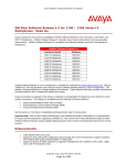
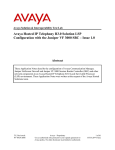
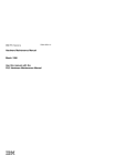
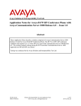
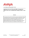
Avaya Solution & Interoperability Test Lab Configuring Avaya Aura® Messaging 6.1 as a Voice Messaging Solution for Avaya Business Communication Manager 450 Release 6.0 with SIP trunking through Avaya Aura® Session Manager 6.1 – Issue 1.0 Abstract These Application Notes describe a sample configuration of Avaya Aura® Messaging 6.1 as a voice mail solution for Avaya Business Communication Manager 450 6.0. In this configuration Avaya Aura® Messaging and Business Communication Manager 450 are connected to Avaya Aura® Session Manager R6.1 over SIP trunks. Avaya Aura® Session Manager provides SIP proxy/routing functionality, routing SIP sessions across a TCP/IP network with centralized routing policies. Avaya Aura® Messaging supports Business Communication Manager 450 endpoints for voice messaging features such as greeting menu, user mailbox services and transfer functionalities. These Application Notes provide information for the setup, configuration, and verification of the call flows tested for this solution. PM; Reviewed: SPOC 02/26/2013 Solution & Interoperability Test Lab Application Notes ©2013 Avaya Inc. All Rights Reserved. 1 of 47 AAM61SM61BCM60 1. Introduction These Application Notes describe a sample configuration of Avaya Aura® Messaging 6.1 as a voice mail solution for Avaya Business Communication Manager (BCM) 450 6.0. In this configuration Avaya Aura® Messaging and Avaya BCM are connected to Avaya Aura® Session Manager over SIP trunks. Avaya Aura® Session Manager provides SIP proxy/routing functionality, routing SIP sessions across a TCP/IP network with centralized routing policies. Avaya Aura® Messaging provides unified communications features such as greeting menu, user mailbox services and transfer functionalities. Avaya Aura® Communication Manager is setup as an emulated PSTN connected to Avaya BCM through T1 connection. 2. Interoperability Testing and Test Result Interoperability was tested between Avaya Business Communication Manager and Avaya Aura® Messaging with SIP trunking through Avaya Aura® Session Manager. 2.1. Interoperability Compliance Testing Interoperability testing was executed between a variety of Avaya telephones such as Digital, UNIStim registered to Business Communication Manager, Avaya SIP phones registered to Session Manager and Avaya H323, Digital phones registered to Communication Manager. The focus was to verify call and messaging functionality between Communication Manager, Business Communication Manager and Avaya Aura® Messaging in a SIP network with trunking through Session Manager. The following Avaya Aura® Messaging capabilities were covered: No Answer Personal Greetings Bypass Greetings Message Waiting Indication Reply Call Forwarding Multiple Call Forwarding Call Transfer Simultaneous Calls Personal Operator Personal Operator – No Answer Auto Attendant Auto Attendant – No Answer Call to Forward All (forward to messaging access number) endpoint. Call to Busy endpoint (messaging access number is set if this endpoint busy) All the call is forwarded to pilot number. The following Avaya Aura® Messaging capabilities were not in scope for this testing: Call Sender Reach Me Notify Me PM; Reviewed: SPOC 02/26/2013 Solution & Interoperability Test Lab Application Notes ©2013 Avaya Inc. All Rights Reserved. 2 of 47 AAM61SM61BCM60 2.2. Test Results and Observations Interoperability testing of Avaya Aura® Messaging 6.1 Single Server as a voice mail solution for Avaya Business Communication Manager with SIP Trunking through Avaya Aura® Session Manager R6.1 was successful. 3. Reference Configuration Figure 1 below illustrates the configuration used in these Application Notes. The sample configuration shows an enterprise with Avaya BCM communicating with the Avaya Aura® Messaging via a SIP trunk. The Avaya BCM has an analog, a digital and an IP Telephone connected as endpoints. For security purposes public IP addresses have been masked out or altered in this document. Figure 1: Network Configuration PM; Reviewed: SPOC 02/26/2013 Solution & Interoperability Test Lab Application Notes ©2013 Avaya Inc. All Rights Reserved. 3 of 47 AAM61SM61BCM60 4. Equipment and Software Validated The following equipment and software were used for the sample configuration provided: Equipment S8800 Server S8800 Server S8800 Server G450 with S8300D, emulated PSTN Business Communication Manager 450 2 – Avaya 1140E IP Telephone (SIP) 2- Digital Phones T7316 2 – Analog Phones PM; Reviewed: SPOC 02/26/2013 Software Avaya Aura® Messaging Release 6.1 Avaya Aura® Session Manager Release 6.1 Avaya Aura® System Manager Release 6.1 Avaya Aura® Communication 6.0 PRI, Digital Trunk Interface Module Avaya BCM450 R6 SU 011-201205 Firmware Version: 0625C8J n/a n/a Solution & Interoperability Test Lab Application Notes ©2013 Avaya Inc. All Rights Reserved. 4 of 47 AAM61SM61BCM60 5. Configure Avaya Business Communication Manager with SIP Trunking to Avaya Aura® Session Manager This section describes the procedure for setting up Avaya BCM. The following administration activities will be described: Configure Proxy for Private SIP Trunking Configure the Global setting for SIP Trunking Configure general info for IP Trunks Configure the routing Configure the destination code Configure the private network for dialing plan Configuring the Public network for the dialing plan Configure Target Lines Assign a target line to a selected set Configure Active Sets The highlights in the following screens indicate the values used during the compliance test. Default values may be used for all other fields. Please keep in mind that the values used in this guide may be unique to the example shown. User will have to use values unique to their site, where this solution is being deployed (e.g., site’s IP address, extension numbers, etc). Avaya BCM configurations can be performed through Business Element Management only. PM; Reviewed: SPOC 02/26/2013 Solution & Interoperability Test Lab Application Notes ©2013 Avaya Inc. All Rights Reserved. 5 of 47 AAM61SM61BCM60 5.1. SIP Trunking Configuration This section explains the steps to configure a SIP trunk routing entry that will access the Messaging via Session Manager from the Avaya BCM. 5.1.1. Configure Proxy for Private SIP Trunking After logging into the BCM element manager, configure a private proxy for the SIP trunking by selecting, Configuration Resources IP Trunks SIP Trunking Select the tab Private Proxy to add a proxy as shown in figure below: Domain: the defined domain that the Avaya Aura® Messaging and Avaya Aura® Session Manager system is assigned to. During compliance test bvwdev.com domain is used. IP Address: is Session Manager’s IP. PM; Reviewed: SPOC 02/26/2013 Solution & Interoperability Test Lab Application Notes ©2013 Avaya Inc. All Rights Reserved. 6 of 47 AAM61SM61BCM60 5.1.2. Configure the Global settings for SIP Trunking: Navigate to Configuration Resources IP Trunks SIP Trunking Select the tab Global Settings as shown in figure below: Local Domain: is the defined domain that the AAM and ASM system is assigned to. Call Signaling port: 5060 5.2. IP Trunks Configuration This section describes how to configure the general settings for IP trunk. 5.2.1. General IP trunk settings: Navigate to Configuration Resources IP Trunks General IP Trunk Settings Setup the general information for the IP trunk as below: Forward redirected OLI: First Redirect. Remote capability MWI: checked Send name display: checked. Note: for detail of these setting please refer to Avaya BCM documentation listed in reference Section 12 PM; Reviewed: SPOC 02/26/2013 Solution & Interoperability Test Lab Application Notes ©2013 Avaya Inc. All Rights Reserved. 7 of 47 AAM61SM61BCM60 5.3. Dialing Plan Configuration This section describes how to configure the dialing plan, routes and pool that will be used by the Avaya BCM to communicate with the Avaya Aura Messaging. 5.3.1. Configure the routing: Navigate to Configuration Telephony Dialing Plan Routing In Routes tab to add a new route by click on the Add button. Enter the route number 001 and click OK when Done. Double click on new created Route and assign value to the route as below: Use Pool: BlocA. DN Type: Private The rest of the values leave them as default. 5.3.2. Configure the destination code: Navigate to Configuration Telephony Dialing Plan Routing In Destination Codes tab add a destination code as shown in figure below: Destination Code: 399. The destination code 399 is chosen because the AAM pilot number used in the example is 39990. Normal Route: 001 Absorbed Length: 0 PM; Reviewed: SPOC 02/26/2013 Solution & Interoperability Test Lab Application Notes ©2013 Avaya Inc. All Rights Reserved. 8 of 47 AAM61SM61BCM60 5.3.3. Configure the dialing plan private network: Configuration Telephony Dialing Plan Private Network Configure the private network as shown in figure below: Private Received number length: 5. Private network type: CDP. Private DN length: 5 5.4. Target Lines Configuration This section describes how to configure target lines which will be assigned to telephones that will be used as endpoints connected to the BCM. PM; Reviewed: SPOC 02/26/2013 Solution & Interoperability Test Lab Application Notes ©2013 Avaya Inc. All Rights Reserved. 9 of 47 AAM61SM61BCM60 5.4.1. Configure a target line to a selected set: Navigate to Configuration Telephony Lines Target Lines In the Target Lines screen, select a Line and enter DN to selected Line For example in the figure shown below: Line: 413 has been selected. DN: 22235 has been assigned by clicking on the Add button under the Assigned DNs tab. Note: Add unique set DN to one Target line. Require one line assignment for every telephone device in the system. Also for the assigned set to generate busy tone while it is busy. Select Preferences tab: If Busy field: Busy tone has to be selected as shown in figure below. PM; Reviewed: SPOC 02/26/2013 Solution & Interoperability Test Lab Application Notes ©2013 Avaya Inc. All Rights Reserved. 10 of 47 AAM61SM61BCM60 5.5. Active Sets Configuration This section describes the steps to configure the sets that have been assigned to a line as explained in Section 5.4 5.5.1. Configure the Active sets: Select Configuration Telephony Sets Active Sets Example configuration for Line Access tab of selected active set: Select DN: 22235 Fwd No Answer: 39990 Fwd Busy: 39990 Note: 39990 is the pilot number of Avaya Messaging. Example configuration for Line Assignment tab of selected active set: Vmsg Set: checked so that voice mail can be accessed by the DN 22235 Priv. Received#: 22235 Pub. Received #: 22235. Figures below show the additional configurations to be done to the selected DN which has to be member of the BlocA pool found in the Line Pool Access tab. PM; Reviewed: SPOC 02/26/2013 Solution & Interoperability Test Lab Application Notes ©2013 Avaya Inc. All Rights Reserved. 11 of 47 AAM61SM61BCM60 In the Capabilities and Preferences tab make sure the following options are selected: DND on Busy: checked. Allow redirect: checked. PM; Reviewed: SPOC 02/26/2013 Solution & Interoperability Test Lab Application Notes ©2013 Avaya Inc. All Rights Reserved. 12 of 47 AAM61SM61BCM60 6. Configure Avaya Business Manager 450 with PRI trunk to PSTN 6.1. Administer Resources This section describes how to configure a PRI Trunk on BCM to PSTN. 6.1.1. Administer Application Resource for PRI Trunks These Application Notes assume that the basic configuration has already been administered. This section describes steps for configuring Application Resource for PRI Trunks on BCM to work with Service Provider system. For further information on Avaya Business Communication Manager 450 configuration, please consult references in Section 12. Enable the PRI device on Avaya BCM by select Resources Telephony Resources. Under Configured Device column, select DTM + PRI and then click Enable button if it is not already enable as show in figure below. Configure PRI trunk parameter as highlighted in red box. Others are left as default: Trunk type: PRI Protocol: NI-2 NSF extension: None. B channel selection: Descending Sequential. Clock source: Internal. CO fail: TIA-547A. Interface levels: ISDN. Framing: ESF. Line config: B8ZS. PM; Reviewed: SPOC 02/26/2013 Solution & Interoperability Test Lab Application Notes ©2013 Avaya Inc. All Rights Reserved. 13 of 47 AAM61SM61BCM60 6.1.2. Routing Settings This section describes how to configure the dialing plan, routes and pool that will be used by the Avaya BCM to connect to PSTN. Navigate to Telephony Dialing Plan Routing. In Routes tab to add a new route to PSTN by click on the Add button. Enter the route number 002 and click OK when Done. Double click on new created Route and assign value to the route as below, other leave as default: Use Pool: BlocB. DN Type: Private. Service Type: Tie. 6.1.3. Administer Destination Codes To assign Destination Codes to dial to PSTN via PRI. Perform similar step as shown in section 5.3.2 for with the following information Destination Code: 4521. Extension on Avaya Communication manager is 52xxx. Digit 4 to let Avaya BCM route the call through route 002 Normal Route: 002. Absorbed Length: 1. Drop the first digit 4. 6.1.4. Administer Telephony Lines Assign the pool to telephone line by navigate to Telephony Lines Active Physical Lines. Double click on a selected line under the Line Type, choose Pool:BlocB in this example as shown below. PM; Reviewed: SPOC 02/26/2013 Solution & Interoperability Test Lab Application Notes ©2013 Avaya Inc. All Rights Reserved. 14 of 47 AAM61SM61BCM60 6.1.5. Administer Telephony Target Lines Assign a DN: 22234 to an available target line Line: 362. See Section 5.4 for detail procedure. 6.1.6. User/Telephone Sets Configuration for Incoming/Outgoing Call This section show how to configure telephone sets to specific physical line for incoming/outgoing calls to/from a digital set. Select Telephony Sets Active Sets. In the Line Access, select the available digital set which has the Model is T7316/M7310. Assign Priv. OLI: 22234. This will allow the delivery of the Calling Line Identification Display. For incoming call: Assign the line that configured in Section 6.1.5 o this phone by click on the Add button in Line Assignment tab. Enter line number, in this example 362 and click OK. Modify the detail information of the line parameters as values highlighted in red boxes in the below figure: Caller ID Set: checked. Vmsg Set: checked. Priv. Received #: 22234. Pub. Received #: 22234. PM; Reviewed: SPOC 02/26/2013 Solution & Interoperability Test Lab Application Notes ©2013 Avaya Inc. All Rights Reserved. 15 of 47 AAM61SM61BCM60 For Outgoing Call: Select tab Line Pool Access tab, click Add button to add BlocB. Click OK from the Add Line Pool pop up to complete as shown below: PM; Reviewed: SPOC 02/26/2013 Solution & Interoperability Test Lab Application Notes ©2013 Avaya Inc. All Rights Reserved. 16 of 47 AAM61SM61BCM60 7. Configure Avaya Aura® Communication Manager as Emulated PSTN – PRI Trunk Configuration This section focuses on configuring the T1 trunks on Avaya Communication Manager to serve as service provider to Avaya Business Communication Manager, and provides a sample routing using Automatic Alternate Routing (AAR). The configuration procedures include the following areas: Administer DS1 circuit pack Administer trunk group Administer signaling group Administer trunk group members Administer route pattern Administer public unknown numbering Administer uniform dial plan Administer AAR analysis PM; Reviewed: SPOC 02/26/2013 Solution & Interoperability Test Lab Application Notes ©2013 Avaya Inc. All Rights Reserved. 17 of 47 AAM61SM61BCM60 7.1. Administer DS1 circuit pack Log into the System Access Terminal (SAT), and administer a DS1 circuit pack to be used for Connectivity to BCM. Use the add ds1 001v6 command. Note that the actual slot number may vary. In this case “001v6” is used as the slot number. Enter the following values for the specified fields, and retain the default values for the remaining fields. Submit these changes. Note: The Interface field must be complementary on both switches. For the sample configuration, Avaya Communication Manager is administered as the network/master (“peermaster”), and Avaya BCM is administered as the “user/slave”. add ds1 001v6 Page 1 of 2 DS1 CIRCUIT PACK Location: 001V6 Name: To BCM Bit Rate: 1.544 Line Coding: b8zs Line Compensation: 1 Framing Mode: esf Signaling Mode: isdn-pri Connect: pbx Interface: peer-master TN-C7 Long Timers? n Peer Protocol: Q-SIG Interworking Message: PROGress Side: b Interface Companding: mulaw CRC? n Idle Code: 11111111 DCP/Analog Bearer Capability: 3.1kHz T303 Timer(sec): 4 Disable Restarts? n Slip Detection? n Near-end CSU Type: other Echo Cancellation? n 7.2. Administer Trunk Group Administer an ISDN trunk group to interface with Avaya BCM. Use the add trunk-group n command; where n is an available trunk group number. Enter the following values for the specified fields, and retain the default values for the remaining fields. add trunk-group 1 Page 1 of 21 TRUNK GROUP Group Number: 1 Group Type: isdn CDR Reports: y Group Name: Tie Route to BCM COR: 1 TN: 1 TAC: 100 Direction: two-way Outgoing Display? n Carrier Medium: PRI/BRI Dial Access? n Busy Threshold: 255 Night Service: Queue Length: 0 Service Type: tie Auth Code? n TestCall ITC: rest Far End Test Line No: TestCall BCC: 4 PM; Reviewed: SPOC 02/26/2013 Solution & Interoperability Test Lab Application Notes ©2013 Avaya Inc. All Rights Reserved. 18 of 47 AAM61SM61BCM60 Navigate to Page 2. For the Supplementary Service Protocol field, enter “b” for Q-SIG. For the Format field, enter “unk-unk”. Retain the default values for the remaining fields. add trunk-group 1 Group Type: isdn Page TRUNK PARAMETERS Codeset to Send Display: 6 Max Message Size to Send: 260 Supplementary Service Protocol: b 2 of 21 Codeset to Send National IEs: 6 Charge Advice: none Digit Handling (in/out): enbloc/enbloc Trunk Hunt: cyclical Incoming Calling Number - Delete: Bit Rate: 1200 Disconnect Supervision - In? y Answer Supervision Timeout: 0 Administer Timers? n PM; Reviewed: SPOC 02/26/2013 Digital Loss Group: 13 Insert: Format: unk-unk Synchronization: async Duplex: full Out? n CONNECT Reliable When Call Leaves ISDN? n Delay Call Setup When Accessed Via IGAR? n Solution & Interoperability Test Lab Application Notes ©2013 Avaya Inc. All Rights Reserved. 19 of 47 AAM61SM61BCM60 Navigate to Page 3. Enable the Send Name, Send Calling Number, and Send Connected Number fields. For the Format field, enter “unknown”. Submit these changes. add trunk-group 1 TRUNK FEATURES ACA Assignment? n Page 3 of 21 Measured: none Wideband Support? n Internal Alert? n Maintenance Tests? y Data Restriction? n NCA-TSC Trunk Member: 23 Send Name: y Send Calling Number: y Used for DCS? n Hop Dgt? n Send EMU Visitor CPN? n Suppress # Outpulsing? n Format: unknown Outgoing Channel ID Encoding: preferred UUI IE Treatment: service-provider Replace Restricted Numbers? Replace Unavailable Numbers? Send Connected Number: Hold/Unhold Notifications? Modify Tandem Calling Number: no n n y y Send UUI IE? y Send UCID? n Send Codeset 6/7 LAI IE? y Ds1 Echo Cancellation? n Apply Local Ringback? n Show ANSWERED BY on Display? y Network (Japan) Needs Connect Before Disconnect? n 7.3. Administer Signaling Group Administer an ISDN signaling group for the new trunk group to use for signaling. Use the add signaling-group n command, where n is an available signaling group number. For the Primary D-Channel field, enter the slot number for the DS1 circuit pack from Section 7.1. For the Trunk Group for NCA TSC and Trunk Group for Channel Selection fields, enter the ISDN trunk group number. For the Supplementary Service Protocol field, enter “b” for QSIG. Maintain the default values for the remaining fields, and submit these changes. add signaling-group 1 GROUP isdn-pri y Max number of NCA TSC: 10 001V624 Max number of CA TSC: 10 Trunk Group for NCA TSC: 1 Trunk Group for Channel Selection: 1 X-Mobility/Wireless Type: NONE TSC Supplementary Service Protocol: b Network Call Transfer? n Group Number: 1 PM; Reviewed: SPOC 02/26/2013 SIGNALING Group Type: Associated Signaling? Primary D-Channel: Solution & Interoperability Test Lab Application Notes ©2013 Avaya Inc. All Rights Reserved. 20 of 47 AAM61SM61BCM60 7.4. Administer Trunk Group Members Use the change trunk-group n command, where n is the trunk group number added in Section 7.2. Navigate to Page 3. For the NCA-TSA Trunk Member field, enter the highest trunk group member number to use for routing of tandem QSIG call independent signaling connections. change trunk-group 1 21 TRUNK FEATURES ACA Assignment? n Page Measured: Internal Alert? Data Restriction? Send Name: Used for DCS? n Hop Dgt? Suppress # Outpulsing? n Format: unknown Outgoing Channel ID Encoding: preferred UUI provider 3 of none Wideband Support? n Maintenance Tests? n NCA-TSC Trunk Member: y Send Calling Number: n Send EMU Visitor CPN? n y 23 y n IE Treatment: service- Replace Restricted Numbers? Replace Unavailable Numbers? Send Connected Number: Hold/Unhold Notifications? Modify Tandem Calling Number: no n n y y Send UUI IE? y Send UCID? n Send Codeset 6/7 LAI IE? y Ds1 Echo Cancellation? n Apply Local Ringback? n Show ANSWERED BY on Display? y Network (Japan) Needs Connect Before Disconnect? n Navigate to Page 4. Shown below are default values that were used during testing. change trunk-group 1 Page 4 of 21 QSIG TRUNK GROUP OPTIONS TSC Method for Auto Callback: Diversion by Reroute? Path Replacement? Path Replacement with Retention? Path Replacement Method: SBS? Display Forwarding Party Name? Character Set for QSIG Name: QSIG Value-Added? PM; Reviewed: SPOC 02/26/2013 drop-if-possible y y n better-route n y eurofont n Solution & Interoperability Test Lab Application Notes ©2013 Avaya Inc. All Rights Reserved. 21 of 47 AAM61SM61BCM60 Navigate to Page 5 and 6. Enter all 23 ports of the DS1 circuit pack into the Port fields, and the corresponding Code and Sfx fields will be populated automatically. Enter the ISDN signaling group number into the Sig Grp fields as shown below. Submit these changes. change trunk-group 1 Page 5 of 21 TRUNK GROUP Administered Members (min/max): 1/23 Total Administered Members: 23 GROUP MEMBER ASSIGNMENTS 1: 2: 3: 4: 5: 6: 7: Port 001V601 001V602 001V603 001V604 001V605 001V606 001V607 Code Sfx Name MM710 B MM710 B MM710 B MM710 B MM710 B MM710 B MM710 B Night Sig Grp 1 1 1 1 1 1 1 7.5. Administer Route Pattern Create a route pattern for the new ISDN trunk group to use for routing. Use the change route pattern n command, where n is an available route pattern. Enter the following values for the specified fields, and retain the default values for the remaining fields. Submit these changes. add route-pattern 1 Page 1 of Pattern Number: 5 Pattern Name: BCM-Qsig-Route SCCAN? n Secure SIP? n Grp FRL NPA Pfx Hop Toll No. Inserted No Mrk Lmt List Del Digits Dgts 1: 1 0 2: 3: 4: 5: 6: BCC VALUE TSC CA-TSC 0 1 2 M 4 W Request 1: y y y y y n PM; Reviewed: SPOC 02/26/2013 3 DCS/ IXC QSIG Intw n user n user n user n user n user n user ITC BCIE Service/Feature PARM y as-needed rest No. Numbering LAR Dgts Format Subaddress unk-unk none Solution & Interoperability Test Lab Application Notes ©2013 Avaya Inc. All Rights Reserved. 22 of 47 AAM61SM61BCM60 7.6. Administer Public Unknown Numbering Use the change public-unknown-numbering 0 command, to define the calling party number to be sent to Avaya Business Communication Manager. Add an entry for the trunk group defined in Section 7.2. In the example shown below, all calls originating from a 6-digit extension beginning with 7 and routed to trunk group 1 will result in the 5-digit calling number to be sent. Submit these changes. change public-unknown-numbering 0 Page 1 of 2 NUMBERING - PUBLIC/UNKNOWN FORMAT Total Ext Ext Trk CPN CPN Len Code Grp(s) Prefix Len Total Administered: 1 6 7222 1 6 Maximum Entries: 9999 7.7. Administer Uniform Dial Plan This section provides a sample AAR routing used for routing calls with dialed digits 7xxxxx to Avaya BCM. Use the change uniform-dialplan 0 command, and add an entry to specify use of AAR for routing of digits 7xxxxx. Enter the following values for the specified fields and retain the default values for the remaining fields. Submit these changes. change uniform-dialplan 0 UNIFORM DIAL PLAN TABLE Page 1 of 2 Percent Full: 0 Matching Pattern 7222 Len Del 6 1 Insert Digits Node Net Conv Num aar n 7.8. Administer AAR Analysis Use the change aar analysis 0 command, and add an entry to specify how to route the calls to Avaya BCM. Enter the following values for the specified fields and retain the default values for the remaining fields. Submit these changes. change aar analysis 0 Page AAR DIGIT ANALYSIS TABLE Location: all Dialed String 7222 PM; Reviewed: SPOC 02/26/2013 Total Min Max 6 6 Route Pattern 1 Call Type aar 2 Percent Full: 1 Node Num Solution & Interoperability Test Lab Application Notes ©2013 Avaya Inc. All Rights Reserved. 1 of ANI Reqd n 23 of 47 AAM61SM61BCM60 8. Configure Avaya Aura® Session Manager This section provides the procedures for configuring Session Manager as provisioned in the reference configuration. Session Manager is comprised of two functional components: the Session Manager server and the System Manager server. All SIP call provisioning for Session Manager is performed through the System Manager Web interface and is then downloaded into Session Manager. The following sections assume that Session Manager and System Manager have been installed and that network connectivity exists between the two platforms. In this section, the following topics are discussed: SIP Domains Locations SIP Entities Entity Links Time Ranges Routing Policy Dial Patterns Synchronization 8.1. Configure SIP Domain Launch a web browser, enter http://<IP address of System Manager>/SMGR in the URL, and log in with the appropriate credentials. Navigate to Routing Domains, and click on the New button (not shown) to create a new SIP Domain. Enter the following values and use default values for remaining fields: Name – Enter the Authoritative Domain Name, e.g “bvwdev.com”. Type – Select SIP Click Commit to save. The following screen shows the Domains page used during the compliance test. PM; Reviewed: SPOC 02/26/2013 Solution & Interoperability Test Lab Application Notes ©2013 Avaya Inc. All Rights Reserved. 24 of 47 AAM61SM61BCM60 8.2. Configure Locations Locations are used to identify logical and/or physical locations where SIP Entities reside, for purposes of bandwidth management or location-based routing. Navigate to Routing Locations, and click on the New button (not shown) to create a new SIP endpoint location. General section Enter the following values and use default values for remaining fields. Enter a descriptive Location name in the Name field. Enter a description in the Notes field if desired. Location Pattern section Click Add and enter the following values: Enter the IP address information for the IP address Pattern (e.g. “10.1.2.*”) Enter a description in the Notes field if desired. Repeat steps in the Location Pattern section if the Location has multiple IP segments. Modify the remaining values on the form, if necessary; otherwise, retain the default values. Click on the Commit button. Repeat all the steps for each new Location. The following screen shows the Locations page used during the compliance test. PM; Reviewed: SPOC 02/26/2013 Solution & Interoperability Test Lab Application Notes ©2013 Avaya Inc. All Rights Reserved. 25 of 47 AAM61SM61BCM60 8.3. Configure SIP Entities A SIP Entity must be added for Session Manager and for each network component that has a SIP trunk provisioned to Session Manager. During the compliance test, the following SIP Entities were configured: Session Manager itself. Avaya Aura Messaging BCM Navigate to Routing SIP Entities, and click on the New button (not shown) to create a new SIP entity. Provide the following information: General section Enter the following values and use default values for remaining fields. Enter a descriptive Location name in the Name field. Enter IP address for signaling interface on each BCM, Avaya Aura Messaging. From the Type drop down menu select a type that best matches the SIP Entity. o For Session Manager, select Session Manager o For Messaging, select Modular Messaging o For BCM, select Others Enter a description in the Notes field if desired. Select the appropriate time zone. Accept the other default values. Click on the Commit button to save each SIP entity. The following screens show the SIP Entity page used during the compliance test. Repeat all the steps for each new entity PM; Reviewed: SPOC 02/26/2013 Solution & Interoperability Test Lab Application Notes ©2013 Avaya Inc. All Rights Reserved. 26 of 47 AAM61SM61BCM60 8.4. Configure Entity Links Entity Links define the connections between the SIP Entities and Session Manager. In the compliance test, the following entity links are defined from Session Manager. Session Manager BCM Session Manager Avaya Aura Messaging Navigate to Routing Entity Links, and click on the New button (not shown) to create a new entity link. Provide the following information: Enter a descriptive name in the Name field. In the SIP Entity 1 drop down menu, select the Session Manager SIP Entity created in Section 0. In the Protocol drop down menu, select the protocol to be used (e.g. “UDP” or “TCP”). In the Port field, enter the port to be used (e.g. “5060”). In the SIP Entity 2 drop down menu, select an entity. In the Port field, enter the port to be used (e.g. “5060”). Check the Trusted box. Enter a description in the Notes field if desired. Click on the Commit button to save each Entity Link definition. The following screen shows an Entity Links page (between Session Manager and Messaging) used during the compliance test. Repeat the steps to define Entity Links between Session Manager and Avaya BCM. PM; Reviewed: SPOC 02/26/2013 Solution & Interoperability Test Lab Application Notes ©2013 Avaya Inc. All Rights Reserved. 27 of 47 AAM61SM61BCM60 8.5. Time Ranges The Time Ranges form allows admission control criteria to be specified for Routing Policies. In the reference configuration, no restrictions were used. To add a Time Range, navigate to Routing Time Ranges, and click on the New button (not shown). Provide the following information: Enter a descriptive Location name in the Name field (e.g. “24/7”). Check each day of the week. In the Start Time field, enter “00:00”. In the End Time field, enter “23:59”. Enter a description in the Notes field if desired. Click the Commit button. The following screen shows the Time Range page used during the compliance test. PM; Reviewed: SPOC 02/26/2013 Solution & Interoperability Test Lab Application Notes ©2013 Avaya Inc. All Rights Reserved. 28 of 47 AAM61SM61BCM60 8.6. Configure Routing Policy Routing Policies associates destination SIP Entities with Time of Day admission control parameters and Dial Patterns. In the reference configuration, Routing Policies are defined for: Business Communication Manager. To add a Routing Policy, navigate to Routing Routing Policy, and click on the New button (not shown) on the right. Provide the following information: General section Enter a descriptive name in the Name field. Enter a description in the Notes field if desired. SIP Entity as Destination section Click the Select button. Select the SIP Entity that will be the destination for this call (not shown). Click the Select button and return to the Routing Policy Details form. Time of Day section Leave default values. Click Commit to save Routing Policy definition. The following screen shows the Routing Policy used for the compliance test. Repeat the steps to define routing policies to others Entities. PM; Reviewed: SPOC 02/26/2013 Solution & Interoperability Test Lab Application Notes ©2013 Avaya Inc. All Rights Reserved. 29 of 47 AAM61SM61BCM60 8.7. Dial Patterns Dial Patterns define digit strings to be matched for inbound and outbound calls. In addition, the domain in the request URI is also examined. In the compliance test, the following dial patterns are defined from Session Manager. 222xx – SIP endpoints in BCM 39990 – Avaya Aura Messaging Pilot Number. To add a Dial Pattern, select Routing Dial Patterns, and click on the New button (not shown) on the right. During the compliance test, 5 digit dial plan was utilized. Provide the following information: General section Enter a unique pattern in the Pattern field (e.g. “399”). In the Min field enter the minimum number of digits (e.g. “5”). In the Max field enter the maximum number of digits (e.g. “5”). In the SIP Domain field drop down menu select the domain that will be contained in the Request URI received by Session Manager from BCM and AAM. Enter a description in the Notes field if desired. Originating Locations and Routing Policies section Click on the Add button and a window will open (not shown). Click on the boxes for the appropriate Originating Locations and Routing Policies that pertain to this Dial Pattern. o Location All. o Routing Policies SM_to_AAM. o Click on the Select button and return to the Dial Pattern window. Click the Commit button to save the new definition. The following screen shows the dial pattern used for Messaging during the compliance test. Repeat the same for Avaya BCM with Pattern: 222. PM; Reviewed: SPOC 02/26/2013 Solution & Interoperability Test Lab Application Notes ©2013 Avaya Inc. All Rights Reserved. 30 of 47 AAM61SM61BCM60 9. Configure Avaya Aura® Messaging Messaging was configured for SIP communication with Session Manager and also to add Avaya BCM, Communication Manager Subscribers. The procedures include the following areas: Administer Sites Administer Telephony Integration Administer Dial Rules Administer Class of Service to enable Message Waiting Administer Subscribers See references in Section 12 for standard installation and configuration information. General knowledge of the configuration tools and interfaces is assumed. 9.1. Administer Sites A Messaging access number and a Messaging Auto Attendant number needs to be defined. Log into the Avaya Aura Messaging System Management Interface (SMI) and go to Administration Messaging Messaging System (Storage) Sites. In the right panel fill in the following: Under Main Properties: Messaging access number (internal) PM; Reviewed: SPOC 02/26/2013 Enter a Messaging Pilot number Solution & Interoperability Test Lab Application Notes ©2013 Avaya Inc. All Rights Reserved. 31 of 47 AAM61SM61BCM60 Scroll down to the Site Internal Dial Plan section. Under Site Internal Dial Plan: Short Extension Length Enter the number of digits in extensions Short Mailbox Length Enter the number of digits in mailbox numbers PM; Reviewed: SPOC 02/26/2013 Solution & Interoperability Test Lab Application Notes ©2013 Avaya Inc. All Rights Reserved. 32 of 47 AAM61SM61BCM60 Scroll down to the Auto Attendant section. Under Auto Attendant: Auto Attendant Select “Enabled” Auto Attendant pilot number Enter an Auto Attendant number Keypad entry Select “ENHANCED” Speech recognition Select “Enabled” Click Save to save changes. PM; Reviewed: SPOC 02/26/2013 Solution & Interoperability Test Lab Application Notes ©2013 Avaya Inc. All Rights Reserved. 33 of 47 AAM61SM61BCM60 9.2. Administer Telephony Integration A SIP trunk needs to be configured from Messaging to Session Manager. Log into the Messaging System Management Interface (SMI) and go to Administration Messaging Telephony Settings (Application) Telephony Integration. In the right panel fill in the following: Under Basic Configuration: Extension Length: Switch Integration Type: Enter the length of extensions SIP Under SIP Specific Configuration: Transport Method: “TCP” Connection 1: Enter the Session Manager signaling IP address and TCP port number Messaging Address Enter the Messaging IP address and TCP port number SIP Domain Enter the Messaging and Session Manager domain names Click Save to save changes. PM; Reviewed: SPOC 02/26/2013 Solution & Interoperability Test Lab Application Notes ©2013 Avaya Inc. All Rights Reserved. 34 of 47 AAM61SM61BCM60 9.3. Configure Dial Rules Navigate to Administration MessagingServer Settings (Application) Dial Rules to configure the dial rules. Set the Dial plan handling style: Site definition based, as shown below. Next select the Edit Dial-Out Rules button to verify the appropriate parameters for outbound dialing from Avaya Aura® Messaging were set above. These dial rules help Avaya Aura® Messaging send the correct number and combination of digits when originating a call to Communication Manager, whether the call is destined for another extension or ultimately expected to be routed to the PSTN. For the sample configuration, 7-digit extensions were used on Avaya Communication Manager so any time Avaya Aura Messaging originates a call to an extension it should send the 7-digit number and not attempt to insert or delete any digits. Scroll down to the section titled Dial-out Test Numbers. Enter in a number in the appropriate section and select the Test button to see how Avaya Aura® Messaging would dial that number. As shown below the number 7785002 is treated as an internal number and is dialed intact, whereas the test number 408-555-7086 is treated as a long-distance national number which requires a 9 prefixed as an access code. PM; Reviewed: SPOC 02/26/2013 Solution & Interoperability Test Lab Application Notes ©2013 Avaya Inc. All Rights Reserved. 35 of 47 AAM61SM61BCM60 PM; Reviewed: SPOC 02/26/2013 Solution & Interoperability Test Lab Application Notes ©2013 Avaya Inc. All Rights Reserved. 36 of 47 AAM61SM61BCM60 9.4. Configure Class of Service Verify Messaging Waiting is enabled for all subscribers. Use Administration Messaging Messaging System (Storage) Class of Service. Select Standard from the Class of Service drop-down menu. Under General section, enter the following value and use default values for remaining fields. Set Message Waiting Indicator (MWI) on user’s desk phone: checked. Dial-out privilege: Local. Under Greetings section, enter for Two Greetings (different greetings for busy and noanswer) field to allow subscribers to record different personal greetings for busy and noanswer scenarios. Click Save (not shown) to save changes. The following screen shows the settings defined for the “Standard” Class of Service in the test configuration. PM; Reviewed: SPOC 02/26/2013 Solution & Interoperability Test Lab Application Notes ©2013 Avaya Inc. All Rights Reserved. 37 of 47 AAM61SM61BCM60 9.5. Administer Subscribers Log into the Messaging System Management Interface (SMI) and go to Administration Messaging. In the left panel, under Messaging System (Storage) select User Management. In the right panel fill in the following: First Name Enter first name Last Name Enter last name Display Name Enter display name ASCII name Enter the ASCII name Site Enter site defined in Section 9.1 Mailbox Number Enter desired mailbox number i.e. “22235” Internal identifier Enter the name for internal use Numeric address Enter the mailbox number Extension Enter desired extension number i.e. “22235” PM; Reviewed: SPOC 02/26/2013 Solution & Interoperability Test Lab Application Notes ©2013 Avaya Inc. All Rights Reserved. 38 of 47 AAM61SM61BCM60 Scroll down on the page to Class of Service. Class of Service Select a Class of Service Pronounceable Name Enter a pronounceable name to be used when dialing the extension using voice commands MWI Enabled Select “Yes” to enable the MWI light on phones New Password/Confirm Password Enter desired extension password Next logon password change Select the Checkbox Click Save to save changes. PM; Reviewed: SPOC 02/26/2013 Solution & Interoperability Test Lab Application Notes ©2013 Avaya Inc. All Rights Reserved. 39 of 47 AAM61SM61BCM60 10. Verification Steps 10.1.Verify Avaya Aura® Session Manager Operational Status 10.1.1. Verify Avaya Aura® Session Manager is Operational Navigate to Elements Session Manager Dashboard (not shown) to verify the overall system status for Session Manager. Specifically, verify the status of the following fields as shown below: Tests Pass: Security Module: Service State: Session Manager Instances status. Navigate to Elements Session Manager System Status Security Module Status (not shown) to view more detailed status information on the status of Security Module for the specific Session Manager. Verify the Status column displays “Up” as shown below. PM; Reviewed: SPOC 02/26/2013 Solution & Interoperability Test Lab Application Notes ©2013 Avaya Inc. All Rights Reserved. 40 of 47 AAM61SM61BCM60 10.1.2. Verify SIP Entity Link Status Navigate to Elements Session Manager System Status SIP Entity Monitoring (not shown) to view more detailed status information for one of the SIP Entity Links. Select the SIP Entity for BCM from the All Monitored SIP Entities table (not shown) to open the SIP Entity, Entity Link Connection Status page. In the All Entity Links to SIP Entity: BCM450_34table, verify the Conn. Status for the link is “Up” as shown below. As described above the Entity link connection status can also be viewed for the AAM. Verify that the Conn. Status is also Up (not shown). PM; Reviewed: SPOC 02/26/2013 Solution & Interoperability Test Lab Application Notes ©2013 Avaya Inc. All Rights Reserved. 41 of 47 AAM61SM61BCM60 10.2.Verify Avaya Aura® Messaging 10.2.1. Verify no answer call Make a call from a Avaya BCM endpoint to another Avaya BCM endpoint and verify that the call covers to Messaging upon no answer. Leave a voice message. Verify that the MWI light of the called phone turns on. From the receiving Avaya BCM endpoint, dial the Messaging access number to retrieve the message. Verify that the Messaging system identifies the Avaya BCM endpoint and that the voice message can be retrieved. Verify that the MWI light turns off. Log into the Messaging System Management Interface (SMI) and go to Administration Messaging. In the left panel, under Logs select User Activity. In the right panel fill in the following: Under User Activity Log: Mailbox Number Start Date End Date Enter the BCM extension that received the voicemail. Enter an appropriate start date and time. Enter an appropriate end date and time. Click Display button and verify that a listing of the detailed activities is displayed into the bottom portion of the right hand pane. Verify that there is an entry showing the message left by a subscriber (in this case 22234). Also verify that there is an entry showing the message being retrieved. PM; Reviewed: SPOC 02/26/2013 Solution & Interoperability Test Lab Application Notes ©2013 Avaya Inc. All Rights Reserved. 42 of 47 AAM61SM61BCM60 10.2.2. Test calls can be made from Avaya Aura Messaging to phones that are configured with mailboxes. To perform this test, select Administration Messaging. In the left panel, under Diagnostics select Diagnostics (Application). In the right panel fill in the following: Select the test(s) to run: Telephone number: Select Call-out from the drop down menu. Enter the number to call. Click on Run Tests to start the test. The phone will ring and when answered a test message is played. The Results section of the page will update indicating that the call was ok as shown below. PM; Reviewed: SPOC 02/26/2013 Solution & Interoperability Test Lab Application Notes ©2013 Avaya Inc. All Rights Reserved. 43 of 47 AAM61SM61BCM60 10.2.3. Message Waiting Indicator (MWI) light on phones. To perform this test, select Administration Messaging. In the left panel, under Diagnostics select Diagnostics (Application). In the right panel fill in the following: Select the test(s) to run: Extension number: Select MWI from the drop down menu. Enter the number of the phone to test. Click on Run Tests to start the test. The phones MWI light will turn on and off. The Results section of the page will update with information about the test as shown below. PM; Reviewed: SPOC 02/26/2013 Solution & Interoperability Test Lab Application Notes ©2013 Avaya Inc. All Rights Reserved. 44 of 47 AAM61SM61BCM60 10.2.4. Other call scenarios Call to Forward All(forward to messaging access number) endpoint Call to Busy endpoint (messaging access number is set if this endpoint busy) All the call is forwarded to pilot number. PM; Reviewed: SPOC 02/26/2013 Solution & Interoperability Test Lab Application Notes ©2013 Avaya Inc. All Rights Reserved. 45 of 47 AAM61SM61BCM60 11. Conclusion Interoperability testing of Avaya Aura® Messaging 6.1 Single Server as a voice mail solution for Avaya Business Communication Manager with SIP Trunking through Avaya Aura® Session Manager R6.2 was successfulm. See section 2.2for detail of test result and observation. 12. Additional References This section provides references to the product documentation relevant to this Application Note. Documentation for Avaya products may be found at http://support.avaya.com. Avaya Aura® Session Manager 1) 2) 3) 4) 5) Avaya Aura® Session Manager Overview, Doc ID 03-603323 Installing and Configuring Avaya Aura® Session Manager Avaya Aura® Session Manager Case Studies Maintaining and Troubleshooting Avaya Aura® Session Manager, Doc ID 03-603325 Administering Avaya Aura® Session Manager, Doc ID -3-603324 Avaya Aura® Messaging 6) Administering Avaya Aura® Messaging 6.1 CID: 151610 December 2011 7) Using Avaya Aura® Messaging 6.1 December 2011 8) Implementing Avaya Aura® Messaging 6.1 CID: 150976 October 2011 Avaya Business Communication Manager 450 9) Avaya Business Communication Manager 6.0 Planning and Engineering NN40170-200 10) Avaya Business Communication Manager 6.0 Configuration - Telephony NN40170-502 Avaya Communication Manager 11) Avaya Aura® Communication Manager Screen Reference Release 6.2 03-602878 Issue 3.0 February 2012 PM; Reviewed: SPOC 02/26/2013 Solution & Interoperability Test Lab Application Notes ©2013 Avaya Inc. All Rights Reserved. 46 of 47 AAM61SM61BCM60 ©2013 Avaya Inc. All Rights Reserved. Avaya and the Avaya Logo are trademarks of Avaya Inc. All trademarks identified by ® and ™ are registered trademarks or trademarks, respectively, of Avaya Inc. All other trademarks are the property of their respective owners. The information provided in these Application Notes is subject to change without notice. The configurations, technical data, and recommendations provided in these Application Notes are believed to be accurate and dependable, but are presented without express or implied warranty. Users are responsible for their application of any products specified in these Application Notes. Please e-mail any questions or comments pertaining to these Application Notes along with the full title name and filename, located in the lower right corner, directly to the Avaya Solution & Interoperability Test Lab at [email protected] PM; Reviewed: SPOC 02/26/2013 Solution & Interoperability Test Lab Application Notes ©2013 Avaya Inc. All Rights Reserved. 47 of 47 AAM61SM61BCM60