1
SMB
Using the Nortel Business
Ethernet Switch 50 Series
ATTENTION
Clicking on a PDF hyperlink takes you to the appropriate page. If necessary,
scroll up or down the page to see the beginning of the referenced section.
NN47924-301
.
Document status: Standard
Document version: 01.01
Document date: October 2006
Copyright © 2006, Nortel Networks
All Rights Reserved.
3
Contents
Preface
9
Before you begin 9
Text conventions 9
Related publications 11
How to get help 11
New in this release
13
Features 13
Release 1.0 13
Introduction
15
Using the Web-based user interface
17
Setting up the Web-based user interface 18
Logging on to the Web-based user interface 19
Logging off from the Web-based user interface 19
Navigating the Web-based user interface 20
Menu and management pages 20
Configuration options 21
Initial configuration 22
Changing the administrator password 23
Adding system information 24
Setting the IP address 24
Setting the IP address manually 25
Setting the IP address automatically 25
BES50 basic configuration
27
Configuring initial settings by using the Quick Start feature 27
Configuring user authentication 29
Configuring user accounts 30
Configuring local and remote logon authentication 31
Configuring port security 32
Configuring event logging 33
Configuring the system logs 33
Configuring the remote logs 35
Setting application filtering 36
SMB
Using the Nortel Business Ethernet Switch 50 Series
NN47924-301 01.01 Standard
1.00 October 2006
Copyright © 2006, Nortel Networks
.
Nortel Networks Confidential
4 Contents
Configuring the system clock 36
Setting the system clock 37
Setting daylight saving time 37
BES50 advanced features configuration
41
Configuring Simple Network Management Protocol 42
Sending an inform message to an SNMP version 2 host 42
Sending an inform message to an SNMP version 3 host 42
Setting community access strings 43
Specifying trap managers and trap types 43
Enabling SNMP service 46
Configuring SNMP version 3 management access 46
Setting the local engine ID 46
Setting a remote engine ID 47
Setting SNMP version 3 views 48
Configuring SNMP version 3 users 49
Changing the assigned group for an SNMP version 3 user 50
Configuring remote SNMP version 3 users 51
Creating SNMP version 3 groups 52
Configuring ports and trunks 55
Configuring interface connections 55
Creating trunk groups 56
Configuring a static trunk 57
Enabling LACP on selected ports 58
Configuring LACP parameters 59
Setting broadcast storm thresholds 60
Configuring port mirroring 61
Configuring rate limits 62
Setting Power over Ethernet 63
Setting the switch power budget 63
Configuring port PoE power priorities 64
Configuring Spanning Tree Algorithm 65
Configuring STA switch settings (global settings) 65
Configuring STA settings for interfaces 67
Configuring IEEE 802.1Q VLANs 69
Assigning ports to VLANs 69
Enabling or disabling GVRP (global setting) 70
Setting up VLANs 70
Adding static members to VLANs (VLAN index) 71
Adding static members to VLANs (port index) 72
Configuring VLAN behavior for interfaces 73
Link Layer Discovery Protocol (LLDP) configuration 75
Configuring the LLDP 75
Configuring the LLDP interfaces 76
SMB
Using the Nortel Business Ethernet Switch 50 Series
NN47924-301 01.01 Standard
1.00 October 2006
Copyright © 2006, Nortel Networks
.
Nortel Networks Confidential
Contents 5
Configuring Class of Service 76
Setting the default priority for interfaces 77
Mapping CoS values to egress queues 77
Selecting the queue mode rules 78
Setting the service weight for traffic classes 79
Enabling IP DSCP priority 80
Mapping DSCP priority 80
Configuring Quality Of Service (QoS) 81
Configuring class maps 81
Configuring policy maps 82
Configuring service policy settings 83
Configuring address tables 84
Changing the aging time 84
Setting static addresses 85
Voice VLAN configuration 85
Configuring voice VLAN on the BES50 (global setting) 85
Configuring voice VLAN on ports 86
Configuring jumbo frames (BES50GE-12/24T PWR only) 87
Configuring 802.1X port authentication 87
Configuring 802.1X global settings 88
Configuring 802.1X port settings 88
Configuring Access Control Lists 90
Configuring an Access Control List 90
Binding a port to an Access Control List 93
BES50 administration
95
Resetting the system 95
Changing a PC IP address 96
Displaying system and switch information 97
Displaying switch hardware and software versions 98
Displaying bridge extension capabilities 98
Displaying log messages 99
Displaying connection status 99
Displaying LACP statistics 100
Displaying local LACP settings and status 100
Displaying remote LACP settings and status 101
Displaying switch power status 102
Displaying port power status 103
Displaying port statistics 103
Displaying STA switch settings (global settings) 106
Displaying STA settings for interfaces 107
Displaying basic VLAN information 109
Displaying current VLANs 109
Displaying LLDP local device information 110
SMB
Using the Nortel Business Ethernet Switch 50 Series
NN47924-301 01.01 Standard
1.00 October 2006
Copyright © 2006, Nortel Networks
.
Nortel Networks Confidential
6 Contents
Displaying LLDP remote device information 110
Displaying detailed LLDP remote information 111
Displaying LLDP device statistics 111
Displaying detailed LLDP device statistics 111
Displaying the address table 112
Displaying system information 113
Displaying 802.1X global settings 113
Displaying 802.1X port statistics 113
Managing firmware 115
Downloading system software from a server 115
Deleting files 116
Setting the startup code 116
Testing port cable connections 117
Troubleshooting 117
Power LED does not light after power on 118
Link LED does not light after connection is made 118
Cannot connect by using a Web browser or SNMP software 119
Forgotten IP address or password 119
Cannot display left menu panel of the Web-based user interface 120
Determining the BES50 IP address allocated by the DHCP server 120
BES50 installation options
Installing the BES50 on a brick or concrete wall
Installing the BES50 on a wood wall 124
Installing the BES50 on a rack 124
123
123
BES50 fundamentals
125
Switch architecture 125
Power over Ethernet capability 126
Network management options 126
Hardware components 126
10/100/1000BASE-T ports 126
Port, PoE, and system status LEDs 127
Power supply socket 128
Reset button 128
Key software features 128
Authentication 129
Access Control Lists 130
Port configuration 130
Rate limiting 131
Port mirroring 131
Port trunking 131
Broadcast storm control 131
Static addresses 131
IEEE 802.1D bridge 132
SMB
Using the Nortel Business Ethernet Switch 50 Series
NN47924-301 01.01 Standard
1.00 October 2006
Copyright © 2006, Nortel Networks
.
Nortel Networks Confidential
Contents 7
Store-and-forward switching 132
Spanning Tree Algorithm 132
Virtual LANs 133
Traffic prioritization 134
Configuration backup and restore 134
Network planning 134
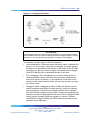
Collapsed backbone 135
Network aggregation plan 135
VLAN connections 136
BES50 advanced features fundamentals
139
Simple Network Management Protocol 139
Local engine ID 140
Remote engine ID 140
Port configuration concepts 141
Trunk groups 141
Power over Ethernet 142
Switch power budget 143
Port PoE power 143
IEEE 802.1Q VLANs 143
Assigning ports to VLANs 144
Tagged and untagged frames 147
GVRP (global setting) 147
Link Layer Discovery Protocol 147
Class of Service 147
Default priority for interfaces 148
CoS values and egress queues 148
Weighted Round-Robin (WRR) queuing 148
Layer 3/4 priorities to CoS values 149
DSCP priority 149
Address tables 149
Static addresses 149
Dynamic addresses 150
Voice VLAN—autodetection device 150
Simple Network Time Protocol 151
Logon authentication protocols 151
Port security 151
802.1X port authentication 152
BES50 reference information
155
System defaults 155
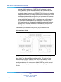
Twisted-pair cable and pin assignments 157
10/100BASE-TX pin assignments 158
Straight-through wiring 159
Crossover wiring 159
SMB
Using the Nortel Business Ethernet Switch 50 Series
NN47924-301 01.01 Standard
1.00 October 2006
Copyright © 2006, Nortel Networks
.
Nortel Networks Confidential
8 Contents
1000BASE-T pin assignments 160
Specifications 161
Compliances 164
SMB
Using the Nortel Business Ethernet Switch 50 Series
NN47924-301 01.01 Standard
1.00 October 2006
Copyright © 2006, Nortel Networks
.
Nortel Networks Confidential
9
Preface
This guide provides information about administering and configuring the
Nortel Business Ethernet Switch 50 (BES50) Series devices. This guide
describes the features of the following Nortel switches:
•
Nortel Business Ethernet Switch BES50GE-12T PWR Gigabit Ethernet
Switch
•
Nortel Business Ethernet Switch BES50GE-24T PWR Gigabit Ethernet
Switch
•
Nortel Business Ethernet Switch BES50FE-12T PWR Fast Ethernet
Switch
•
Nortel Business Ethernet Switch BES50FE-24T PWR Fast Ethernet
Switch
Before you begin
This guide is intended for network administrators who have the following
background:
•
basic knowledge of networks, Ethernet bridging, and IP routing
•
familiarity with networking concepts and terminology
•
basic knowledge of network topologies
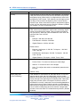
Text conventions
This guide uses the following text conventions.
angle brackets (< >)
Indicate that you choose the text to enter based on the description
inside the brackets. Do not type the brackets when you enter the
command. Example: If the command syntax is
ping <ip address>
you enter
ping 192.168.1.128
bold body text
Indicates objects such as window names, dialog box names, and
icons, as well as user interface objects such as buttons, tabs,
and menu items.
SMB
Using the Nortel Business Ethernet Switch 50 Series
NN47924-301 01.01 Standard
1.00 October 2006
Copyright © 2006, Nortel Networks
.
Nortel Networks Confidential
10 Preface
braces ({})
Indicate required elements in syntax descriptions where there is
more than one option. You must choose only one of the options.
Do not type the braces when you enter the command. Example:
If the command syntax is
show ip {alerts|routes}
you must enter either
show ip alerts
or
show ip routes
but not both.
brackets ([ ])
Indicate optional elements in syntax descriptions. Do not type
the brackets when you enter the command. Example: If the
command syntax is
show ip interfaces [-alerts]
you can enter either
show ip interfaces
or
show ip interfaces -alerts
italic text
Indicates variables in command syntax descriptions. Also
indicates new terms and book titles. Where a variable is two
or more words, the words are connected by an underscore.
Example: If the command syntax is
show at
<valid_route>, valid_route is one variable and you substitute one
value for it.
plain Courier text
Indicates command syntax and system output, for example,
prompts and system messages. Example:
Set Trap Monitor Filters
separator ( > )
Shows menu paths.
Example: Protocols > IP identifies the IP command on the
Protocols menu.
vertical line ( | )
Separates choices for command keywords and arguments. Enter
only one of the choices. Do not type the vertical line when you
enter the command. Example:
If the command syntax is
show ip {alerts|routes}
you enter either
show ip alerts
or
show
ip
routes
but not both.
SMB
Using the Nortel Business Ethernet Switch 50 Series
NN47924-301 01.01 Standard
1.00 October 2006
Copyright © 2006, Nortel Networks
.
Nortel Networks Confidential
How to get help
11
Related publications
For more information about using the BES50 Series switch, see the
Quick Installation Guide for the Nortel Business Ethernet Switch 50
(NN47924-300).
You can print selected technical manuals and release notes for free, directly
from the Internet. Go to www.nortel.com. Find the product for which you
need documentation. Then locate the specific category and model or
version for your hardware or software product. Use Adobe Reader to open
the manuals and release notes, search for the sections you need, and print
them on most standard printers. Go to www.adobe.com to download a
free copy of Adobe Reader.
How to get help
If you purchased a service contract for your Nortel product from a distributor
or authorized reseller, contact the technical support staff for that distributor
or reseller for assistance.
If you purchased a Nortel service program, contact Nortel Technical Support.
The following information is available online:
•
contact information for Nortel Technical Support
•
information about the Nortel Technical Solutions Centers
•
information about the Express Routing Code (ERC) for your product
An ERC is available for many Nortel products and services. When you use
an ERC, your call is routed to a technical support person who specializes in
supporting that product or service. You can locate the ERC for your product
or service online.
The Nortel Support Web page is here:
www.nortel.com
SMB
Using the Nortel Business Ethernet Switch 50 Series
NN47924-301 01.01 Standard
1.00 October 2006
Copyright © 2006, Nortel Networks
.
Nortel Networks Confidential
12 Preface
SMB
Using the Nortel Business Ethernet Switch 50 Series
NN47924-301 01.01 Standard
1.00 October 2006
Copyright © 2006, Nortel Networks
.
Nortel Networks Confidential
13
New in this release
The following sections detail what’s new in Using the Nortel Business
Ethernet Switch 50 Series (NN47924-301) for release 1.00.
Features
See the following sections for information about feature changes:
Release 1.0
This is the first release of Using the Nortel Business Ethernet Switch 50
Series.
SMB
Using the Nortel Business Ethernet Switch 50 Series
NN47924-301 01.01 Standard
1.00 October 2006
Copyright © 2006, Nortel Networks
.
Nortel Networks Confidential
14 New in this release
SMB
Using the Nortel Business Ethernet Switch 50 Series
NN47924-301 01.01 Standard
1.00 October 2006
Copyright © 2006, Nortel Networks
.
Nortel Networks Confidential
15
Introduction
The BES50FE-12/24T PWR and BES50GE-12/24T PWR are high
performance Web-managed switches that deliver performance and
control to your network. The BES50FE-12/24T PWR provides 12/24
full-duplex 10/100BASE-TX ports and the BES50GE-12/24T PWR provides
12/24 full-duplex 1000BASE-T ports that significantly improve network
performance and boost throughput using switch features configured through
the Web-based user interface. With 24/48FE and 24/48GE of throughput
bandwidth, these switches provide the quickest solution to meeting the
growing demands on your network.
Navigation
•
To set up the Web-based user interface for use with the BES50, see
"Using the Web-based user interface" (page 17).
•
To set up the basic BES50 management features, see "BES50 basic
configuration" (page 27).
•
To set up advanced BES50 management features, see "BES50
advanced features configuration" (page 41).
•
To reset the system, to change the IP address, to view system details, or
to manage BES50 firmware, see "BES50 administration" (page 95).
•
For installation options other than those covered by the Quick Installation
Guide for the Nortel Business Ethernet Switch 50 (NN47924-300), see
"BES50 installation options" (page 123).
•
To learn about the basic BES50 management features, see "BES50
fundamentals" (page 125).
•
To learn about the advanced BES50 management features, see "BES50
advanced features fundamentals" (page 139).
•
For system defaults, specifications, compliances, and other reference
information related to the BES50, see "BES50 reference information"
(page 155).
SMB
Using the Nortel Business Ethernet Switch 50 Series
NN47924-301 01.01 Standard
1.00 October 2006
Copyright © 2006, Nortel Networks
.
Nortel Networks Confidential
16 Introduction
SMB
Using the Nortel Business Ethernet Switch 50 Series
NN47924-301 01.01 Standard
1.00 October 2006
Copyright © 2006, Nortel Networks
.
Nortel Networks Confidential
17
Using the Web-based user interface
Use the information in this chapter to understand how to use the Web-based
user interface to view and configure information about the Business Ethernet
Switch (BES) 50 Series switch.
Prerequisites
•
To use the Web-based user interface, you need the following items:
— a computer connected to a network port that is a member of the
management Virtual Local Area Network (VLAN)
— Microsoft Internet Explorer 5.5 or later installed on the administration
computer
•
Prior to accessing the switch from a Web browser, perform the following
tasks:
— "Setting up the Web-based user interface" (page 18).
— If required, configure the switch with a valid IP address, subnet mask,
and default gateway. (Default: 192.168.1.128/255.255.255.0/0.0.0.0)
See "Initial configuration" (page 22).
— Set a new password by using the Web-based user interface.
Web-based user interface access is password controlled. (Default
user name: nnadmin; default password : PlsChgMe!) See "Changing
the administrator password" (page 23).
ATTENTION
The Web pages of the Web-based user interface can load at different speeds
depending on which Web browser you use.
ATTENTION
Web browser capabilities, such as page bookmarking, refresh, and page forward
and page back, function as they would in any other Web site. However, these
capabilities do not enhance the functionality of the Web-based user interface.
Nortel recommends that you use only the navigation tools provided in the
management interface.
SMB
Using the Nortel Business Ethernet Switch 50 Series
NN47924-301 01.01 Standard
1.00 October 2006
Copyright © 2006, Nortel Networks
.
Nortel Networks Confidential
18 Using the Web-based user interface
Navigation
•
"Setting up the Web-based user interface" (page 18)
•
"Logging on to the Web-based user interface" (page 19)
•
"Logging off from the Web-based user interface" (page 19)
•
"Navigating the Web-based user interface" (page 20)
•
"Initial configuration" (page 22)
•
"Changing the administrator password" (page 23)
•
"Adding system information" (page 24)
•
"Setting the IP address" (page 24)
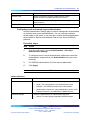
Setting up the Web-based user interface
Nortel recommends that you follow the procedures in this section regarding
Web-based user interface prerequisites before you use the management
features of your switch for the first time.
Procedure steps
Step
Action
1
Check that Java Runtime Environment (JRE) version 1.5.0_07-b03
or later is installed on your PC. Download the latest version from
www.java.com if required.
ATTENTION
The menu on left side of the Web-based user interface may not appear if
the Java Runtime Environment (JRE) is not installed.
2
Ensure the software programs on your PC enable Java script and
Java applets. Refer to the corresponding software documentation for
instructions. Software programs include but are not limited to:
•
Web browser
•
firewall
•
software that controls Java behavior
ATTENTION
The menu on left side of the Web-based user interface may not appear if
Java script and Java applets are disabled.
3
Ensure the software programs on your PC enable Web browser
pop-up dialog boxes. Refer to the corresponding software
SMB
Using the Nortel Business Ethernet Switch 50 Series
NN47924-301 01.01 Standard
1.00 October 2006
Copyright © 2006, Nortel Networks
.
Nortel Networks Confidential
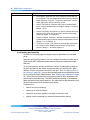
Logging off from the Web-based user interface 19
documentation for instructions. Software programs include but are
not limited to:
•
Web browser
•
firewall
•
software that controls Java behavior
ATTENTION
Some management features of your switch do not work properly if pop-up
dialog boxes are disabled.
—End—
Logging on to the Web-based user interface
Use this procedure to log on to the Web-based user interface.
To access the Web-based user interface you must first enter a password.
Users with Privileged access have Read/Write access to all configuration
parameters and statistics.
ATTENTION
If user input does not occur within 5 minutes, the current session terminates.
Procedure steps
Step
Action
1
In the Web-based user interface address bar, type the IP address
for your host switch. For example, type http://192.168.1.128, and
press Enter.
2
Enter the user name and password, and click OK. (Default user
name: nnadmin. Default password: PlsChgMe!)
—End—
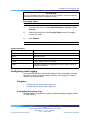
Logging off from the Web-based user interface
Use this procedure to log off from the Web-based user interface.
Procedure steps
Step
Action
1
From the main menu, choose Administration > LogOut.
SMB
Using the Nortel Business Ethernet Switch 50 Series
NN47924-301 01.01 Standard
1.00 October 2006
Copyright © 2006, Nortel Networks
.
Nortel Networks Confidential
20 Using the Web-based user interface
2
Click Logout. A confirmation dialog box appears.
3
Click Ok to log off or click Cancel to cancel the request.
—End—
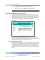
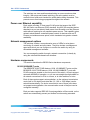
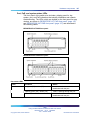
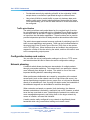
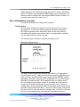
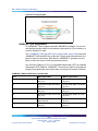
Navigating the Web-based user interface
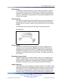
When your Web browser connects with the switch Web agent, the home
page appears as shown in the figure "Home page" (page 20). The home
page displays the main menu on the left side of the screen and System
Information on the right side. Use the main menu links to navigate to other
menus and display configuration parameters and statistics.
Home page
The figure shows the home page for the BES50GE-12T-PWR 12-port
switch. Other than the number of fixed ports, there are no major differences
between the 12-port and 24-port switch user interface.
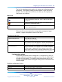
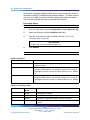
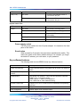
Menu and management pages
Using the onboard Web agent, you can define system parameters, manage
and control the switch and all its ports, or monitor network conditions. The
menu is the same for all pages. It contains a list of six main headings. To
navigate the Web-based user interface menu, click a menu title and then
click one of its options. When you click an option, the corresponding page
appears.
SMB
Using the Nortel Business Ethernet Switch 50 Series
NN47924-301 01.01 Standard
1.00 October 2006
Copyright © 2006, Nortel Networks
.
Nortel Networks Confidential
Navigating the Web-based user interface 21
The first five headings provide options for viewing and configuring switch
parameters. The Support heading provides options to open the online
Help file. Tools are provided in the menu to assist you in navigating the
Web-based user interface.
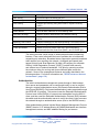
Menu icons
Icon
Description
This icon identifies a menu title. Click on this icon to display
its options.
This icon identifies a menu title option. Click on this icon to
display the corresponding page.
This icon is linked to an action, for example, logout, reset, or
reset to system defaults.
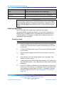
When you click a menu option, the corresponding management page
appears. A page is composed of one or more items.
Management page items
Item
Description
Tables and input forms
Gray cells are read-only.
White cells are input fields.
Check boxes
Enable or disable a selection by selecting or clearing a check
box. When a check mark appears in the box, that selection is
enabled. You disable a selection by clearing the check box.
Icons and buttons
Icons and buttons perform an action concerning the displayed
page or the switch. Some pages include a button that opens
another page or updates the values shown on the current
page. Some pages include icons that initiate an action, such as
reformatting the current displayed data as a bar or pie chart.
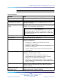
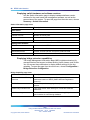
Configuration options
Configurable parameters have a dialog box or a drop-down list. After you
make a configuration change on a page, be sure to click the Submit button
to confirm the new setting. The following table summarizes some of the
common configuration buttons that appear throughout the Web-based user
interface pages.
Web Page configuration buttons
Button
Action
Submit
Saves specified values to the system.
Reload
Refreshes the page with current values.
SMB
Using the Nortel Business Ethernet Switch 50 Series
NN47924-301 01.01 Standard
1.00 October 2006
Copyright © 2006, Nortel Networks
.
Nortel Networks Confidential
22 Using the Web-based user interface
Button
Action
Add
Adds the selected parameter to the configuration.
Delete
Deletes the selected parameter from the configuration.
Remove
Removes the selected parameter from the configuration.
Help
Links directly to Web Help.
ATTENTION
To ensure proper screen refresh, in the Internet Explorer menu, choose Tools >
Internet Options >General > Temporary Internet Files > Settings and select
Every visit to the page as the setting for Check for newer versions of stored
pages.
Initial configuration
Use this procedure to configure an IP address for the switch.
To use the BES50 management features, you must first configure the
BES50 with an IP address that is compatible with the network where it
is being installed. For simplicity, configure the IP address before you
permanently install the switch.
Procedure steps
Step
Action
1
Place your switch close to the PC that you will use to configure it.
It helps if you can see the front panel of the switch while you work
on your PC.
2
Connect the Ethernet port of your PC to any port on the front panel
of your switch.
3
Insert the power adapter into the DC power socket in front of the
switch.
4
Plug the other end of the power adapter into a grounded, 3-pin
socket, AC power source.
5
Check the front-panel LEDs as the device powers on to confirm that
the PWR LED is green. If not, check that the power cable is correctly
plugged in.
6
If the PC IP address is different from the switch but is on the same
subnet, go to the next step. (For example, if the PC and switch both
have addresses that start with 192.168.1.x.) Otherwise, manually
set the IP address for the PC. See "Changing a PC IP address"
(page 96).
SMB
Using the Nortel Business Ethernet Switch 50 Series
NN47924-301 01.01 Standard
1.00 October 2006
Copyright © 2006, Nortel Networks
.
Nortel Networks Confidential
Changing the administrator password 23
The default IP address is 192.168.1.128, the default subnet mask is
255.255.255.0, and the default gateway is 0.0.0.0.
7
Open your Web browser and enter the address http://192.168.1.128.
If you do not see the logon page, check your IP address and repeat
step 3.
If you are using DHCP service, use the Element Manager to launch
the BES50 Web-based user interface.
8
Enter the default user name nnadmin and default password
PlsChgMe!, and click Login.
ATTENTION
If you are using DHCP service, skip the remaining steps.
9
From the main menu, click Configuration > IP.
10
On the IP Configuration page, enter the new IP address, subnet
mask and gateway IP address.
11
Click Submit.
—End—
No other configuration changes are required at this stage, but Nortel
recommends that you change the administrator password before you log off.
Changing the administrator password
Use the User Accounts page to change the switch access passwords.
Procedure steps
Step
Action
1
From the main menu, choose Administration > Security > User
Accounts.
2
In the Change Password table, enter the user name for the account
whose password you want to change.
3
Type in the new password and retype the new password in the
Confirm Password field.
4
Click Change Password.
—End—
SMB
Using the Nortel Business Ethernet Switch 50 Series
NN47924-301 01.01 Standard
1.00 October 2006
Copyright © 2006, Nortel Networks
.
Nortel Networks Confidential
24 Using the Web-based user interface
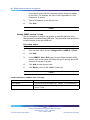
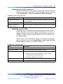
Adding system information
Use the System page to provide a descriptive name, location, and contact
information for the system.
Procedure steps
Step
Action
1
From the main menu, choose Configuration > System.
2
Type a contact name, system name, and system location information.
3
Click Submit.
—End—
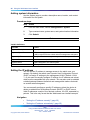
Variable definitions
Variable
Value
System Description
Description of the switch.
System Object ID
This read-only parameter is the Management Information Base
(MIB) II object ID for the switch network management subsystem.
System Up Time
Length of time the management agent has been operational.
System Contact
Administrator responsible for the system.
System Name
Name assigned to the switch system.
Location
The system location.
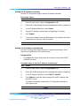
Setting the IP address
You can use an IP address to manage access to the switch over your
network. By default, the switch uses Dynamic Host Configuration Protocol
(DHCP) to assign IP settings to the management VLAN. (Default: VLAN
1.) If you want to manually configure IP settings, the IP address and subnet
mask must be compatible with your network. You may also need to establish
a default gateway between the switch and management stations that exist
on another network segment.
You can manually configure a specific IP address or direct the device to
obtain an address from a Bootstrap Protocol (BOOTP) or DHCP server.
Valid IP addresses consist of four decimal numbers, 0 to 255, separated by
periods. This is the only format that the Web-based user interface accepts.
Navigation
•
"Setting the IP address manually" (page 25)
•
"Setting the IP address automatically" (page 25)
SMB
Using the Nortel Business Ethernet Switch 50 Series
NN47924-301 01.01 Standard
1.00 October 2006
Copyright © 2006, Nortel Networks
.
Nortel Networks Confidential
Setting the IP address 25
Setting the IP address manually
Use the IP Configuration page to set the IP address manually.
Procedure steps
Step
Action
1
From the main menu, choose Configuration > IP.
2
Select the VLAN through which the management station is attached.
3
In the IP Address Mode box, select Static .
4
Type the IP address, subnet mask, and gateway IP address.
5
Click Submit.
6
To save the changes, close the Web-based user interface and start a
new session by using the new IP address.
—End—
Setting the IP address automatically
Use the IP Configuration page to set the IP address dynamically and to
request an IP address from the DHCP server.
Prerequisites
•
To configure the switch dynamically, the network must provide DHCP
or BOOTP services.
Procedure steps to set the IP address automatically
Step
Action
1
From the main menu, choose Configuration > IP.
2
Select the VLAN through which the management station is attached.
3
In the IP Address Mode box, select DHCP or BOOTP.
4
Click Submit to save the setting and get the new IP address from
the DHCP server.
The switch broadcasts a request for IP configuration settings on
each power reset.
—End—
SMB
Using the Nortel Business Ethernet Switch 50 Series
NN47924-301 01.01 Standard
1.00 October 2006
Copyright © 2006, Nortel Networks
.
Nortel Networks Confidential
26 Using the Web-based user interface
Procedure steps to manually request an IP address from the DHCP
server
Step
Action
1
From the main menu, choose Configuration > IP.
2
Click Restart DHCP to immediately request a new address.
The switch broadcasts a request for IP configuration settings on
each power reset.
—End—
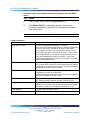
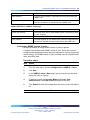
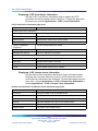
Variable definitions
Variable
Value
Management VLAN
ID of the configured VLAN (Range: 1 to 4094).
This is the only VLAN through which you can gain management
access to the switch. By default, all ports on the switch
are members of VLAN 1, so a management station can be
connected to any port on the switch. However, if other VLANs
are configured and you change the management VLAN, you
can lose management access to the switch. In this case,
reconnect the management station to a port that is a member
of the management VLAN.
IP Address Mode
Select the configuration method.
If you select DHCP or BOOTP, the IP address does not function
until a reply is received from the server. The switch periodically
broadcasts a request for an IP address.
IP Address
For Static IP Address Mode, enter the IP address of the
management access VLAN interface.
Valid IP addresses consist of four numbers, 0 to 255, separated
by periods. (Default: 192.168.1.128)
Subnet Mask
For Static IP Address Mode, enter the host address bits used
for routing to specific subnets. (Default: 255.255.255.0)
Gateway IP address
For Static IP Address Mode, enter the IP address of the
gateway router between this device and management stations
that exist on other network segments. (Default: 0.0.0.0)
MAC Address
The MAC address of this switch.
Restart DHCP
Requests a new IP address from the DHCP server.
SMB
Using the Nortel Business Ethernet Switch 50 Series
NN47924-301 01.01 Standard
1.00 October 2006
Copyright © 2006, Nortel Networks
.
Nortel Networks Confidential
27
BES50 basic configuration
Use the procedures in this chapter to manage the basic configuration of
your Business Ethernet Switch (BES) 50 Series switch.
Navigation
•
"Configuring initial settings by using the Quick Start feature" (page 27)
•
"Configuring user authentication " (page 29)
•
"Configuring event logging" (page 33)
•
"Setting application filtering" (page 36)
•
"Configuring the system clock" (page 36)
Configuring initial settings by using the Quick Start feature
Use the Quick Start page to quickly set up BES50 features including IP
configuration, Simple Network Management Protocol (SNMP) community,
and trap managers.
Procedure steps
Step
Action
1
From the main menu, choose Administration > Quick Start.
2
Enter and select the data for IP configuration, SNMP community and
trap managers as required by your site.
3
Click Submit.
—End—
SMB
Using the Nortel Business Ethernet Switch 50 Series
NN47924-301 01.01 Standard
1.00 October 2006
Copyright © 2006, Nortel Networks
.
Nortel Networks Confidential
28 BES50 basic configuration
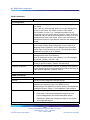
Variable definitions
Variable
Value
IP Configuration
Management VLAN
ID of the configured Virtual Local Area Network (VLAN) (Range:
1 to 4094).
This is the only VLAN through which you can gain management
access to the switch. By default, all ports on the switch
are members of VLAN 1, so a management station can be
connected to any port on the switch. However, if other VLANs are
configured and you change the management VLAN, you can lose
management access to the switch. In this case, reconnect the
management station to a port that is a member of the management
VLAN.
IP Address Mode
Select the configuration method.
If you select Dynamic Host Configuration Protocol (DHCP) or
Bootstrap Protocol (BOOTP), the IP address does not function
until a reply is received from the server. The switch periodically
broadcasts a request for an IP address.
IP Address
For Static IP Address Mode, enter the IP address of the
management access VLAN interface.
Valid IP addresses consist of four numbers, 0 to 255, separated
by periods. (Default: 192.168.1.128)
Subnet Mask
For Static IP Address Mode, enter the host address bits used for
routing to specific subnets. (Default: 255.255.255.0)
Gateway IP address
For Static IP Address Mode, enter the IP address of the gateway
router between this device and management stations that exist on
other network segments. (Default: 0.0.0.0)
MAC Address
The MAC address of this switch.
SNMP Community:
SNMP Community Capability
The number of community strings supported by the BES50.
Current
List of currently configured community strings.
Community String
Type the name of the community string. The name acts like a
password and permits access to the SNMP protocol.
Default strings: PlsChgMe!RO (read-only access), PlsChgMe!RW
(read/write access). Range: 1 to 32 characters, case-sensitive.
Access Mode
Select the access rights for the community string:
•
Read-Only—Authorized management stations can only
retrieve Management Information Base (MIB) objects.
•
Read/Write—Authorized management stations can retrieve
and modify MIB objects.
Trap Managers:
SMB
Using the Nortel Business Ethernet Switch 50 Series
NN47924-301 01.01 Standard
1.00 October 2006
Copyright © 2006, Nortel Networks
.
Nortel Networks Confidential
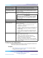
Configuring user authentication
Variable
Value
Trap Manager Capability
The number of trap managers supported by the BES50.
Current
List of currently configured trap managers.
Trap Manager IP Address
Type the IP address of a new management station to receive
notification messages.
Trap Manager Community
String
Specify a valid community string for the new trap manager entry.
(Range: 1 to 32 characters, case-sensitive)
29
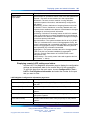
ATTENTION
Nortel recommends that you define this string in the SNMP
Configuratino page for version 1 or 2c clients, or define a
corresponding user name in the SNMPv3 Users page for
version 3 clients.
Trap UDP Port
The UDP port number used by the trap manager.
Trap Version
Select the SNMP version. (Default: 1)
Trap Security Level
For trap version 3, specify one of the following security levels.
(Default: noAuthNoPriv)
Trap Inform
•
noAuthNoPriv—SNMP communications do not use
authentication or encryption.
•
AuthNoPriv—SNMP communications use authentication, but
the data is not encrypted (only available for the SNMPv3
security model).
•
AuthPriv—SNMP communications use both authentication
and encryption (only available for the SNMPv3 security
model).
For version 2c and 3 hosts, notifications are sent as inform
messages. (Default: traps are used)
•
Timeout—The number of seconds to wait for an
acknowledgment before resending an inform message.
(Range: 0 to 2147483647 centiseconds)
•
Retry times—The maximum number of times to resend an
inform message if the recipient does not acknowledge receipt.
(Range: 0 to 255)
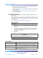
Configuring user authentication
Use the procedures in this section to restrict management access to the
switch and to provide secure network access.
Navigation
•
Use "Configuring user accounts" (page 30) to manually configure
management access rights for users.
SMB
Using the Nortel Business Ethernet Switch 50 Series
NN47924-301 01.01 Standard
1.00 October 2006
Copyright © 2006, Nortel Networks
.
Nortel Networks Confidential
30 BES50 basic configuration
•
Use "Configuring local and remote logon authentication" (page 31) to
remotely configure users access rights.
•
Use "Configuring port security" (page 32) to Configure secure addresses
for individual ports.
•
Use "Configuring 802.1X port authentication" (page 87) to control
access to specific ports.
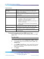
Configuring user accounts
Use the User Accounts page to manually configure management access
rights for users.
The administrator has write access for all parameters governing the onboard
agent. Assign a new administrator password as soon as possible, and store
it in a safe place.
See "Changing the administrator password" (page 23).
Procedure steps
Step
Action
1
From the main menu, choose Administration > Security > User
Accounts.
2
To configure a new user account, enter the user name, access level,
and password. (The default administrator name is nnadmin with
the password PlsChgMe!.)
3
Click Add.
ATTENTION
To change the password for a specific user, enter the user name and new
password, and then confirm the password by entering it again.
—End—
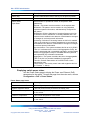
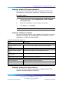
Variable definitions
Variable
Value
Account List
The current list of user accounts and associated access levels.
(Default user name: nnadmin; default password: PlsChgMe!)
New Account
User Name
Enter the name of the user. (Maximum length: 8 characters;
maximum number of users: 16)
SMB
Using the Nortel Business Ethernet Switch 50 Series
NN47924-301 01.01 Standard
1.00 October 2006
Copyright © 2006, Nortel Networks
.
Nortel Networks Confidential
Configuring user authentication
Variable
Value
Access Level
Select Privileged to configure read/write user access.
Select Normal to configure read-only user access.
Password
Enter the user password. (Range: 0 to 8 characters plain text,
case-sensitive)
Confirm Password
Enter a new password for the specified user.
31
Configuring local and remote logon authentication
Use the Authentication Settings page to restrict management access based
on specified user names and passwords. You can manually configure
access rights on the switch, or you can use a remote access authentication
server based on Remote Authentication Dial-In User Server (RADIUS)
protocols.
Procedure steps
Step
Action
1
From the main menu, choose Administration > Security >
Authentication Settings.
2
To configure local or remote authentication preferences, select the
authentication sequence from the Authentication list (one to two
methods).
3
For RADIUS authentication, fill in the required parameters.
4
Click Apply.
—End—
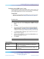
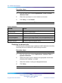
Variable definitions
Variable
Value
Authentication
Select the authentication or authentication sequence:
RADIUS Settings
•
Local—The switch performs user authentication locally.
•
RADIUS—The RADIUS performs user authentication.
•
[authentication sequence]—User authentication occurs in the
indicated sequence. (Local/RADIUS or RADIUS/Local)
Select the authentication or authentication sequence:
•
Global—Provides globally applicable RADIUS settings.
SMB
Using the Nortel Business Ethernet Switch 50 Series
NN47924-301 01.01 Standard
1.00 October 2006
Copyright © 2006, Nortel Networks
.
Nortel Networks Confidential
32 BES50 basic configuration
Variable
Value
•
ServerIndex—Specifies one of five RADIUS servers that can
be configured. The switch attempts authentication by using the
listed sequence of servers. The process ends when a server
either approves or denies access to a user.
•
Server Port Number—Network (UDP) port of authentication
server used for authentication messages. (Range: 1 to 65535;
Default: 1812)
•
Secret Text String—Encryption key used to authenticate logon
access for the client. Do not use blank spaces in the string.
(Maximum length: 20 characters)
•
Number of Server Transmits—Number of times the switch tries
to authenticate logon access through the authentication server.
(Range: 1 to 30; Default: 2)
•
Timeout for a reply—The number of seconds the switch waits
for a reply from the RADIUS server before it resends the
request. (Range: 1 to 65535; Default: 5)
Configuring port security
Use the Port Security page to configure secure addresses for individual
ports.
Using the port security feature, you can configure a switch port with one or
more device MAC addresses authorized to access the network through
that port.
To use port security, specify a maximum number of addresses to allow on
the port and then let the switch dynamically learn the source pair—MAC
address, VLAN—for frames received on the port. See "Configuring 802.1X
port settings" (page 88). You can also manually add secure addresses to the
port by using the Static Address table. See "Setting static addresses" (page
85). When the port reaches the maximum number of MAC addresses, the
selected port stops learning. The MAC addresses already in the address
table are retained and do not age out. Any other device that attempts to use
the port is prevented from accessing the switch.
A secure port:
•
cannot use port monitoring
•
cannot be a multi-VLAN port
•
cannot be used as a member of a static or dynamic trunk
•
should not be connected to a network interconnection device
SMB
Using the Nortel Business Ethernet Switch 50 Series
NN47924-301 01.01 Standard
1.00 October 2006
Copyright © 2006, Nortel Networks
.
Nortel Networks Confidential
Configuring event logging
33
ATTENTION
If a port is disabled (shut down) due to a security violation, it must be manually
reenabled from the Port/Port Configuration page.
Procedure steps
Step
Action
1
From the main menu, choose Administration > Security > Port
Security.
2
Select the check box in the Security Status column to enable
security for a port.
3
Click Submit.
—End—
Variable definitions
Variable
Value
Port
Port number.
Name
Descriptive text.
Security Status
Select to enable port security on the port. (Default: Disabled)
Trunk
Trunk number if port is a member.
LACP
Indicates whether Link Aggregation Control Protocol (LACP) is
enabled or disabled.
Configuring event logging
Use these procedures to control the logging of error messages, including
the type of events recorded in switch memory, and logging to a remote
System Log (syslog) server.
Navigation
•
"Configuring the system logs" (page 33)
•
"Configuring the remote logs" (page 35)
Configuring the system logs
Use the System Logs page to configure system messages logged to flash
or RAM memory.
SMB
Using the Nortel Business Ethernet Switch 50 Series
NN47924-301 01.01 Standard
1.00 October 2006
Copyright © 2006, Nortel Networks
.
Nortel Networks Confidential
34 BES50 basic configuration
Severe error messages logged to flash memory are permanently stored in
the switch to assist in troubleshooting network problems. The flash memory
can store up to 4096 log entries with the oldest entries being overwritten
first when the available log memory exceeds 256 kilobytes.
Procedure steps
Step
Action
1
From the main menu choose Configuration > Log > System Logs.
2
Select the System Log Status Enabled check box.
3
Type the event level for flash and RAM. See the "Event level
messages table" (page 34).
ATTENTION
The flash level must not exceed the RAM level.
4
Click Submit.
—End—
Variable definitions
Variable
Value
System Log Status
Select to enable the logging of debug or error messages to the
logging process.
Flash Level
Enter the highest level of log message to save to the switch
permanent flash memory. For example, specify level 3 to log all
messages from level 0 to level 3 to flash. (Range: 0 to 7. Default:
3)
RAM Level
Enter the highest level of log message to save to the switch
temporary RAM memory. For example, specify level 7 to log all
messages from level 0 to level 7 to RAM. (Range: 0 to 7. Default:
7)
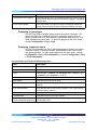
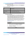
Event level messages table
Level
Severity
Name
Description
7
Debug
Debugging messages
6
Informational
Informational messages only
5
Notice
Normal but significant condition, such as cold start
4
Warning
Warning conditions (such as return false, or unexpected
return)
SMB
Using the Nortel Business Ethernet Switch 50 Series
NN47924-301 01.01 Standard
1.00 October 2006
Copyright © 2006, Nortel Networks
.
Nortel Networks Confidential
Configuring event logging
Level
Severity
Name
Description
3
Error
Error conditions (such as invalid input, or default used)
2
Critical
Critical conditions (such as memory allocation, or free
memory error—resource exhausted)
1
Alert
Immediate action needed
0
Emergency
System unusable
35
Configuring the remote logs
Use the Remote Logs page to configure message logging to remote
servers. You can also limit the error messages sent to only those messages
below a specified level.
Procedure steps
Step
Action
1
From the main menu, choose Configuration > Log > Remote Logs.
2
For Remote Log Status, select the Enabled check box.
3
In the Logging Facility and the Logging Trap fields, type the event
level.
4
To add an IP address to the Host IP List, type the new IP address in
the Host IP Address box, and then click Add.
5
To delete an IP address, click the entry in the Host IP List, and then
click Remove.
6
Click Submit.
—End—
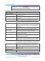
Variable definitions
Variable
Value
Remote Logs
Remote Log Status
Select to enable the logging of debug or error messages to the
remote logging process. (Default: Disabled)
Logging Facility
Type the facility type tag to send in syslog messages. The facility
type is used by the syslog server to dispatch log messages to
an appropriate service, and to sort or store messages in the
corresponding database. (Range: 16 to 23. Default: 23)
SMB
Using the Nortel Business Ethernet Switch 50 Series
NN47924-301 01.01 Standard
1.00 October 2006
Copyright © 2006, Nortel Networks
.
Nortel Networks Confidential
36 BES50 basic configuration
Variable
Value
Logging Trap
Enter the highest level of log message to send to the remote syslog
server. For example, specify level 3 to send all messages from
level 0 to level 3 to the remote server. (Range: 0 to 7. Default: 7)
Host IP Address
Host IP List
List of remote server IP addresses that receive the syslog
messages. The maximum number of host IP addresses allowed
is five.
Host IP Address
Enter the server IP address to add to the Host IP List.
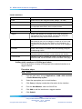
Setting application filtering
Use this procedure to set access control on the switch. The BES50 provides
security control features and controls the access modes, consequently
preventing illegal users from logging on to and accessing switches.
Procedure steps
Step
Action
1
From the main menu, choose Applications > Application Filtering.
2
For each port, select the appropriate check boxes to enable the
required access.
3
Click Submit.
—End—
Variable definitions
Variable
Value
FTP
Select to enable filtering.
SSH
Select to enable filtering.
TELNET
Select to enable filtering.
TFTP
Select to enable filtering.
HTTP
Select to enable filtering.
HTTPs
Select to enable filtering.
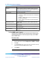
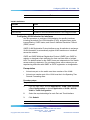
Configuring the system clock
Use the Applications Simple Network Time Protocol (SNTP) page to
configure the system clock manually or automatically, and to configure
daylight saving time on the BES50.
SMB
Using the Nortel Business Ethernet Switch 50 Series
NN47924-301 01.01 Standard
1.00 October 2006
Copyright © 2006, Nortel Networks
.
Nortel Networks Confidential
Configuring the system clock
37
Navigation
•
"Setting the system clock" (page 37)
•
"Setting daylight saving time" (page 37)
Setting the system clock
Use this procedure to set the system clock manually or automatically.
ATTENTION
Manually set system time is not maintained upon reset of the BES50 hardware
or software.
Procedure steps
Step
Action
1
From the main menu, choose Applications > SNTP.
2
To set time manually:
a. Select Set the system time manually.
b. In the Manual table, type the value for each of the Hours,
Minutes, Seconds, Month, Day, and Year fields.
ATTENTION
The Year field must be at least 2001.
3
To set time automatically:
a. Select Set the system time using Simple Network Time
Protocol (SNTP) automatically.
b. From the Time Zone list, select the appropriate time zone.
c. Complete the settings in the Automatic and SNTP Server tables
as required.
See "Setting daylight saving time" (page 37) for details.
4
Click Submit.
—End—
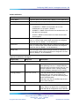
Setting daylight saving time
Use this procedure to configure daylight saving time on the BES50.
Prerequisites
•
Select the automatic system time configuration option.
SMB
Using the Nortel Business Ethernet Switch 50 Series
NN47924-301 01.01 Standard
1.00 October 2006
Copyright © 2006, Nortel Networks
.
Nortel Networks Confidential
38 BES50 basic configuration
Procedure steps
Step
Action
1
From the main menu, choose Applications > SNTP.
2
In the Automatic table, select the Daylight Saving check box, and
then select the daylight saving configuration type. (USA, Europe,
Custom)
3
In the Time Set Offset field, type the number of minutes to offset the
original time to achieve daylight saving time. (This value is typically
set to 60 minutes.)
4
If you select Custom as the daylight saving configuration type, type
the start and end date and time in the FROM and TO fields, or select
the Recurring check box to configure a custom recurring daylight
saving time.
5
Click Submit.
—End—
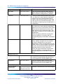
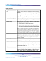
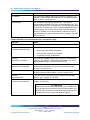
Variable definitions
Variable
Value
Set Time
Select the method for setting the system time. (Options: set
the system time manually or set the system time automatically
using SNTP.)
Manual
For manual time setting, enter the time and date.
If the time is set manually, the system clock resets each time
the switch is rebooted.
Automatic
For automatic time setting, configure the switch so the SNTP
automatically sets the time and date. Enter the values for the
parameters as required.
•
Time Zone—Select your time zone.
•
Daylight Saving—Select the daylight saving configuration
type. (Options: USA, Europe, or Custom)
•
Time Set Offset—For custom settings, enter the time offset
from the time zone.
•
Recurring—Select to use the daylight saving feature for a
specific time period.
•
From/To—Enter the applicable dates and times for daylight
saving use.
SMB
Using the Nortel Business Ethernet Switch 50 Series
NN47924-301 01.01 Standard
1.00 October 2006
Copyright © 2006, Nortel Networks
.
Nortel Networks Confidential
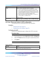
Configuring the system clock
39
Variable
Value
Server 1/Server 2
For automatic time setting, type the IP address for up to two
SNTP servers. The switch attempts to update the time from
the first server; if this fails, it attempts an update from the
second server.
Polling Interval
For automatic time setting, select the interval between sending
requests for a time update from a time server. (Range: 16 to
16384 seconds. Default: 16 seconds)
SMB
Using the Nortel Business Ethernet Switch 50 Series
NN47924-301 01.01 Standard
1.00 October 2006
Copyright © 2006, Nortel Networks
.
Nortel Networks Confidential
40 BES50 basic configuration
SMB
Using the Nortel Business Ethernet Switch 50 Series
NN47924-301 01.01 Standard
1.00 October 2006
Copyright © 2006, Nortel Networks
.
Nortel Networks Confidential
41
BES50 advanced features configuration
Use these procedures to set up the Business Ethernet Switch (BES) 50
advanced management features.
Navigation
•
"Configuring Simple Network Management Protocol" (page 42)
•
"Configuring ports and trunks" (page 55)
•
"Creating trunk groups" (page 56)
•
"Setting broadcast storm thresholds" (page 60)
•
"Configuring port mirroring" (page 61)
•
"Configuring rate limits" (page 62)
•
"Setting Power over Ethernet" (page 63)
•
"Configuring Spanning Tree Algorithm " (page 65)
•
"Configuring IEEE 802.1Q VLANs" (page 69)
•
"Link Layer Discovery Protocol (LLDP) configuration" (page 75)
•
"Configuring Class of Service " (page 76)
•
"Configuring Quality Of Service (QoS)" (page 81)
•
"Configuring address tables" (page 84)
•
"Voice VLAN configuration" (page 85)
•
"Configuring 802.1X port authentication" (page 87)
•
"Configuring Access Control Lists " (page 90)
SMB
Using the Nortel Business Ethernet Switch 50 Series
NN47924-301 01.01 Standard
1.00 October 2006
Copyright © 2006, Nortel Networks
.
Nortel Networks Confidential
42 BES50 advanced features configuration
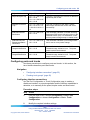
Configuring Simple Network Management Protocol
Use these procedures to set up Simple Network Management Protocol
(SNMP) and security on your BES50.
Navigation
•
"Sending an inform message to an SNMP version 2 host" (page 42)
•
"Sending an inform message to an SNMP version 3 host" (page 42)
•
"Setting community access strings" (page 43)
•
"Specifying trap managers and trap types" (page 43)
•
"Enabling SNMP service" (page 46)
•
"Configuring SNMP version 3 management access" (page 46)
Sending an inform message to an SNMP version 2 host
You can send an inform message to an SNMP version 2 host by completing
the following procedures.
1. Enable the SNMP agent. See "Enabling SNMP service" (page 46).
2. Enable trap inform messages. See "Specifying trap managers and trap
types" (page 43).
3. Create a view with the required notification messages. See "Setting
SNMP version 3 views" (page 48).
4. Create a group that includes the required notify view. See "Creating
SNMP version 3 groups" (page 52).
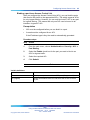
Sending an inform message to an SNMP version 3 host
You can send an inform message to an SNMP version 3 host by completing
the following procedures.
1. Enable the SNMP agent. See "Enabling SNMP service" (page 46).
2. Enable trap inform messages. See "Specifying trap managers and trap
types" (page 43).
3. Create a view with the required notification messages. See "Setting
SNMP version 3 views" (page 48).
4. Create a group that includes the required notify view. See "Creating
SNMP version 3 groups" (page 52).
5. Specify a remote engine ID where the user resides. See "Setting a
remote engine ID" (page 47).
6. Configure a remote user. See "Configuring remote SNMP version 3
users" (page 51).
SMB
Using the Nortel Business Ethernet Switch 50 Series
NN47924-301 01.01 Standard
1.00 October 2006
Copyright © 2006, Nortel Networks
.
Nortel Networks Confidential
Configuring Simple Network Management Protocol
43
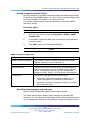
Setting community access strings
Use this procedure to configure community strings and related trap functions
for clients by using SNMP version 1 and v2c. List all community strings used
for IP trap managers in this table, to a maximum of five.
For security reasons, Nortel recommends that you remove the default
community strings.
Procedure steps
Step
Action
1
From the main menu, choose Configuration > SNMP > SNMP
Configuration.
2
In the SNMP Community table, type a community string and select
an access mode.
3
Click Add to save your configuration settings.
—End—
SNMP Configuration page items
Item
Description
SNMP Community Capability
The maximum number of community strings that the BES50
supports. (Maximum number supported: 5)
Current
List of currently configured community strings.
Community String
Type the name of the community string. The name acts like a
password and permits access to the SNMP protocol. (Default
strings: PlsChgMe!RO [read-only access], PlsChgMe!RW
[read/write access]. Range: 1 to 32 characters, case-sensitive.)
Access Mode
Specify the access rights for the community string:
•
Read-Only—Authorized management stations can only
retrieve Management Information Base (MIB) objects.
•
Read/Write—Authorized management stations can retrieve
and modify MIB objects.
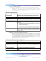
Specifying trap managers and trap types
Use the SNMP Configuration page to specify trap managers.
The switch issues traps indicating status changes to specified trap
managers. You must specify trap managers so the switch reports key events
to your management station by using network management platforms such
SMB
Using the Nortel Business Ethernet Switch 50 Series
NN47924-301 01.01 Standard
1.00 October 2006
Copyright © 2006, Nortel Networks
.
Nortel Networks Confidential
44 BES50 advanced features configuration
as the Element Manager. You can specify up to five management stations
to receive authentication failure messages and other notification messages
from the switch.
By default, the switch issues notifications as trap messages. The recipient
of a trap message does not send a response to the switch. Therefore,
traps are not reliable as inform messages, which include a request for
acknowledgement of receipt. Informs can be used to ensure that the host
receives critical information. However, inform messages consume more
system resources because they must be kept in memory until a response is
received. Inform messages also add to network traffic.
If you specify an SNMP version 3 host, then the Trap Manager Community
String is interpreted as an SNMP user name. If you use SNMP version 3
authentication or encryption options (authNoPriv or authPriv), you must
first define the user name in the SNMP version 3 Users page to enable
password authentication and SNMP access to the switch. However, if
you specify a SNMP version 3 host with the no authentication (noAuth)
option, an SNMP user account is automatically generated, and the switch
authorizes SNMP access for the host.
Prerequisites
•
For SNMP version 3 authentication or encryption options (authNoPriv or
authPriv), you must first define the user name in the SNMP version 3
Users page. See "Configuring SNMP version 3 users" (page 49).
Procedure steps
Step
Action
1
From the main menu, choose Configuration > SNMP > SNMP
Configuration.
2
In the Trap Managers table, enter a trap manager IP address and
trap manager community string for each management station that
receives trap messages.
3
For SNMP version 2 and version 3 clients, specify the trap inform
message settings.
4
For SNMP version 3 clients, specify the UDP port, trap version, and
trap security level.
5
Click Add.
6
Select the check boxes for Enable Authentication and Enable
Link-up and Link-down Traps to indicate the trap types.
7
Click Submit.
SMB
Using the Nortel Business Ethernet Switch 50 Series
NN47924-301 01.01 Standard
1.00 October 2006
Copyright © 2006, Nortel Networks
.
Nortel Networks Confidential
Configuring Simple Network Management Protocol
45
—End—
Variable definitions
Variable
Value
Trap Manager Capability
The number of trap managers that the BES50 supports.
Current
List of currently configured trap managers.
Trap Manager IP Address
Type the IP address of a new management station to receive
notification messages.
Trap Manager Community
String
Specify a valid community string for the new trap manager entry.
(Range: 1 to 32 characters, case-sensitive.)
ATTENTION
Nortel recommends that you define this string in the SNMP
Configuration page for Version 1 or 2c clients, or define a
corresponding user name in the SNMP version 3 Users page
for Version 3 clients.
Trap UDP Port
The UDP port number used by the trap manager.
Trap Version
Select the SNMP version. (Default: 1)
Trap Security Level
For trap version 3, specify one of the following security levels.
(Default: noAuthNoPriv)
Trap Inform
•
noAuthNoPriv—SNMP communications do not use
authentication or encryption.
•
AuthNoPriv—SNMP communications use authentication, but
the data is not encrypted.
•
AuthPriv—SNMP communications use both authentication
and encryption.
For version 2c and 3 hosts, notifications are sent as inform
messages. (Default: traps are used)
•
Timeout—The number of seconds to wait for an
acknowledgment before resending an inform message.
(Range: 0 to 2 147 483 647 centiseconds)
•
Retry times—The maximum number of times to resend an
inform message if the recipient does not acknowledge receipt.
(Range: 0 to 255)
Enable Authentication Traps
Select to issue a notification message to specified IP trap
managers whenever authentication of an SNMP request fails.
(Default: Enabled)
Enable Link-up and
Link-down Traps
Select to issue a notification message whenever a port link is
established or broken. (Default: Enabled)
SMB
Using the Nortel Business Ethernet Switch 50 Series
NN47924-301 01.01 Standard
1.00 October 2006
Copyright © 2006, Nortel Networks
.
Nortel Networks Confidential
46 BES50 advanced features configuration
Enabling SNMP service
Use the SNMP Agent page to enable SNMP service for all management
clients (versions 1, 2c, 3).
Procedure steps
Step
Action
1
From the main menu, choose Configuration > SNMP > Agent
Status.
2
Select the Enable check box.
3
Click Submit.
—End—
Variable definitions
Variable
Value
SNMP Agent Status
Select to enable SNMP on the switch.
Configuring SNMP version 3 management access
Use these procedures to configure SNMP version 3 management access to
the BES50.
Navigation
•
"Setting the local engine ID" (page 46)
•
"Setting a remote engine ID" (page 47)
•
"Setting SNMP version 3 views" (page 48)
•
"Configuring SNMP version 3 users" (page 49)
•
"Changing the assigned group for an SNMP version 3 user" (page 50)
•
"Configuring remote SNMP version 3 users" (page 51)
•
"Creating SNMP version 3 groups" (page 52)
Setting the local engine ID
Use this procedure to set the SNMP version 3 engine ID on the BES50 if it
is different from the default value or if it has been deleted.
ATTENTION
If this local default engine ID is deleted or changed, all SNMP users are cleared
and all existing users must be reconfigured.
SMB
Using the Nortel Business Ethernet Switch 50 Series
NN47924-301 01.01 Standard
1.00 October 2006
Copyright © 2006, Nortel Networks
.
Nortel Networks Confidential
Configuring SNMP version 3 management access 47
Prerequisites
•
Change the default engine ID before you configure other parameters.
Procedure steps
Step
Action
1
From the main menu, choose Configuration > SNMPv3 > Engine
ID.
2
Type an engine ID, to a maximum of 26 hexadecimal characters.
If you specify fewer than 26 characters, trailing zeroes are added
to the value. For example, the value 1234 is equivalent to 1234
followed by 22 zeroes.
3
Click Save.
—End—
Setting a remote engine ID
Use the Remove Engine ID page to set the SNMP version 3 engine ID
for a remote device.
To send inform messages to an SNMP version 3 user on a remote device,
you must first specify the engine identifier for the SNMP agent on the remote
device where the user resides. The remote engine ID is used to compute
the security digest for authenticating and encrypting packets sent to a user
on the remote host.
SNMP passwords are localized by using the engine ID of the authoritative
agent. For inform messages, the authoritative SNMP agent is the remote
agent. You therefore need to configure the remote agent SNMP engine ID
before you can send proxy requests or inform messages to it.
Prerequisites
•
Change the default engine ID before you configure other parameters.
Procedure steps
Step
Action
1
From the main menu, choose Configuration > SNMPv3 > Remote
Engine ID.
2
Type an engine ID, to a maximum of 26 hexadecimal characters.
SMB
Using the Nortel Business Ethernet Switch 50 Series
NN47924-301 01.01 Standard
1.00 October 2006
Copyright © 2006, Nortel Networks
.
Nortel Networks Confidential
48 BES50 advanced features configuration
If you specify fewer than 26 characters, trailing zeroes are added
to the value. For example, the value 1234 is equivalent to 1234
followed by 22 zeroes.
3
Type an IP address for the remote host.
4
Click Add.
—End—
Setting SNMP version 3 views
Use this procedure to restrict user access to specified portions of the
Management Information Base (MIB) tree. The predefined view defaultview
includes access to the entire MIB tree.
Procedure steps
Step
Action
1
From the main menu, choose Configuration > SNMPv3 > Views.
2
Click New.
3
In the SNMPv3 View—Edit page, for each Object Identifier (OID)
subtree, type a view name and select the type to specify which OID
subtrees to include or exclude.
4
Click Add to save the new view.
5
Click Back to return to the SNMPv3 Views list.
—End—
Variable definitions—SNMPv3 View—Edit page
Variable
Value
View Name
Type the name of the SNMP view. (Range: 1 to 64 characters)
Current
The listing of OID subtrees configured for the selected SNMP
version 3 view.
SMB
Using the Nortel Business Ethernet Switch 50 Series
NN47924-301 01.01 Standard
1.00 October 2006
Copyright © 2006, Nortel Networks
.
Nortel Networks Confidential
Configuring SNMP version 3 management access 49
Variable
Value
OID Subtrees
Type the object identifier of the MIB tree branch that defines the
SNMP view.
Type
Select to indicate whether the object identifier of the MIB tree
branch is included in or excluded from the SNMP view.
Variable definitions—SNMPv3 Views page
Variable
Value
[check box column]
Select the check box for each SNMP version 3 view that you want
to view or delete.
Name
The name of the SNMP view. (Range: 1 to 64 characters)
OID Subtrees
Click the hyperlink to view details of the currently configured object
identifiers of the MIB tree branch that defines the SNMP view.
Configuring SNMP version 3 users
Use this procedure to assign SNMP version 3 users to groups.
A unique name defines each SNMP version 3 user. Each user must be
configured with a specific security level and assigned to a group (community
access string). The SNMP version 3 group restricts users to a specific read,
write, and notify view.
Procedure steps
Step
Action
1
From the main menu, choose Configuration > SNMPv3 > Users.
2
Click New.
3
In the SNMPv3 Users—New page, type a name for the user and
assign the user to a group.
4
If required, select the Security Model and Level, User
Authentication, and Data Privacy settings for the user.
5
Click Submit to save the configuration and return to the User Name
list.
—End—
SMB
Using the Nortel Business Ethernet Switch 50 Series
NN47924-301 01.01 Standard
1.00 October 2006
Copyright © 2006, Nortel Networks
.
Nortel Networks Confidential
50 BES50 advanced features configuration
Variable definitions
Variable
Value
User Name
Type the name of the user connecting to the SNMP agent.
(Range: 1 to 32 characters)
Group Name
Type the name of the SNMP group to which the user is assigned
or select a preexisting group name from the list. (Range: 1 to
32 characters)
Security Model
Select the user security model. (SNMP v1, v2c, or v3.)
Security Level
For security model 3, select the security level used:
•
noAuthNoPriv—SNMP communications do not use
authentication or encryption. (Default)
•
AuthNoPriv—SNMP communications use authentication, but
the data is not encrypted.
•
AuthPriv—SNMP communications use both authentication
and encryption.
Authentication
For AuthNoPriv or AuthPriv security level, select the user
authentication method. (Options: MD5, SHA. Default: MD5)
Authentication Password
For AuthNoPriv or AuthPriv security level, type an authorization
password with a minimum of eight plain text characters.
Privacy
The encryption algorithm used for data privacy; only 56-bit DES is
currently available.
Changing the assigned group for an SNMP version 3 user
Use the SNMPv3 Users page to change the assigned group of an SNMP
version 3 user.
Procedure steps
Step
Action
1
From the main menu, choose Configuration > SNMPv3 > Users.
2
In the Actions column for the user that you wish to update, click
Change Group.
3
On the SNMPv3 Users-Edit table, click the option button and enter
the name of a new group, or click the option button and select an
existing group from the list.
4
Click Submit.
—End—
SMB
Using the Nortel Business Ethernet Switch 50 Series
NN47924-301 01.01 Standard
1.00 October 2006
Copyright © 2006, Nortel Networks
.
Nortel Networks Confidential
Configuring SNMP version 3 management access 51
Configuring remote SNMP version 3 users
Use this procedure to assign remote SNMP version 3 users to groups. The
remote engine ID is used to compute the security digest for authenticating
and encrypting packets sent to a user on the remote host.
Prerequisites
•
Specify the engine identifier for the SNMP agent on the remote device
where the user resides. See "Setting a remote engine ID" (page 47).
Procedure steps
Step
Action
1
From the main menu, choose Configuration > SNMPv3 > Remote
Users.
2
Click New.
3
If the remote engine ID is not configured, the Remote Engine ID
dialog box appears. Click OK to access the Remote Engine ID
configuration page. See "Setting a remote engine ID" (page 47) to
configure the remote engine ID before proceeding to the next step.
4
In the Remote Users—New page, type a name for the user and
assign the user to a group.
5
Select the Security Model and Level, User Authentication, and
Data Privacy settings for the user.
6
Click Submit.
—End—
Variable definitions
Variable
Value
User Name
Type the name of the user connecting to the SNMP agent.
(Range: 1 to 32 characters)
Group Name
Type the name of the SNMP group to which the user is assigned
or select a preexisting group name from the list. (Range: 1 to
32 characters)
SMB
Using the Nortel Business Ethernet Switch 50 Series
NN47924-301 01.01 Standard
1.00 October 2006
Copyright © 2006, Nortel Networks
.
Nortel Networks Confidential
52 BES50 advanced features configuration
Variable
Value
Engine IP
Select the engine identifier for the SNMP agent on the remote
device where the remote user resides. You must specify the
remote engine identifier before you configure a remote user. (See
"Setting a remote engine ID" (page 47))
Security Model
The user security model.
Security Level
The security level used for the user:
•
noAuthNoPriv—SNMP communications use no authentication
or encryption.
•
AuthNoPriv—SNMP communications use authentication, but
the data is not encrypted.
•
AuthPriv—SNMP communications use both authentication
and encryption.
Authentication Protocol
Select the user authentication method. (Options: MD5, SHA;
Default: MD5)
Authentication Password
Type an authorization password with a minimum of eight plain
text characters.
Privacy Protocol
The encryption algorithm use for data privacy; only 56-bit DES is
currently available.
Privacy Password
Type a privacy password with a minimum of eight plain text
characters.
Creating SNMP version 3 groups
An SNMP version 3 group sets the access policy for its assigned users,
restricting them to specific read, write, and notify views. You can use the
predefined default groups or create new groups to map a set of SNMP
users to SNMP views.
Procedure steps
Step
Action
1
From the main menu, choose Configuration > SNMPv3 > Groups.
2
Click New.
3
In the New Group page, type a group name, and select a security
model and level and the SNMP version 3 views.
4
Click Submit.
—End—
SMB
Using the Nortel Business Ethernet Switch 50 Series
NN47924-301 01.01 Standard
1.00 October 2006
Copyright © 2006, Nortel Networks
.
Nortel Networks Confidential
Configuring SNMP version 3 management access 53
Variable definitions
Variable
Value
Group Name
Type the name of the SNMP group. (Range: 1 to 32 characters)
Security Model
Select the group security model. (SNMP v1, v2c, or v3.)
Security Level
For security model 3, select the security level used:
•
noAuthNoPriv—SNMP communications do not use
authentication or encryption. (Default)
•
AuthNoPriv—SNMP communications use authentication, but
the data is not encrypted.
•
AuthPriv—SNMP communications use both authentication
and encryption.
Read View
Click the upper option button and type a name for the read access
view, or click the lower option button and select the configured
view from the list. (Range: 1 to 64 characters)
Write View
Click the upper option button and type a name for the write access
view, or click the lower option button and select the configured
view from the list. (Range: 1 to 64 characters)
Notify View
Click the upper option button and type a name for notifications, or
click the lower option button and select the configured view from
the list. (Range: 1 to 64 characters)
Supported notification messages
Object ID
Description
newRoot
1.3.6.1.2.1.17.0.1
This trap indicates that the sending agent is the
new Spanning Tree root. A bridge sends the
trap soon after its election as the new root, such
as upon expiration of the Topology Change
Timer immediately subsequent to its election.
topologyChange
1.3.6.1.2.1.17.0.2
This trap indicates that a configured port
transitioned from the Learning state to the
Forwarding state, or from the Forwarding state
to the Discarding state.
This trap is not sent if a newRoot trap is sent
for the same transition.
1.3.6.1.6.3.1.1.5.1
This trap indicates that the SNMP version 2
entity, acting in an agent role, is reinitializing
itself and that its configuration may be altered.
Object label
RFC 1493 Traps
SNMP version 2 Traps
coldStart
SMB
Using the Nortel Business Ethernet Switch 50 Series
NN47924-301 01.01 Standard
1.00 October 2006
Copyright © 2006, Nortel Networks
.
Nortel Networks Confidential
54 BES50 advanced features configuration
Object label
Object ID
Description
warmStart
1.3.6.1.6.3.1.1.5.2
This trap indicates that the SNMP version 2
entity, acting in an agent role, is reinitializing
itself such that its configuration is unaltered.
linkDown
1.3.6.1.6.3.1.1.5.3
This trap indicates that the SNMP entity, acting
in an agent role, detects that the ifOperStatus
object for one of its communication links is
about to enter the down state from some other
state (but not from the notPresent state). This
other state is indicated by the included value of
ifOperStatus.
linkUp
1.3.6.1.6.3.1.1.5.4
This trap indicates that the SNMP entity, acting
in an agent role, detects that the ifOperStatus
object for one of its communication links left the
down state and transitioned into some other
state (but not into the notPresent state). This
other state is indicated by the included value of
ifOperStatus.
These are legacy notifications and therefore
must be enabled in conjunction with the
corresponding traps on the SNMP Configuration
menu.
authenticationFailure
1.3.6.1.6.3.1.1.5.5
This trap signifies that the SNMP version 2
entity, acting in an agent role, has received
a protocol message that is not properly
authenticated. While all implementations of the
SNMP version 2 must be capable of generating
this trap, the snmpEnableAuthenTraps object
indicates whether this trap is generated.
These are legacy notifications and therefore
must be enabled in conjunction with the
corresponding traps on the SNMP Configuration
menu.
risingAlarm
1.3.6.1.2.1.16.0.1
This trap generates when an alarm entry
crosses its rising threshold and generates an
event configured for sending SNMP traps.
fallingAlarm
1.3.6.1.2.1.16.0.2
This trap generates when an alarm entry
crosses its falling threshold and generates an
event configured for sending SNMP traps.
1.3.6.1.4.1.202.20.28
.63.2.1.0.11.3.6.1.4.1
.202.20.41.63.2.1.0.1
This trap is sent when the power state changes.
RMON Events (V2)
Private Traps
swPowerStatus
ChangeTrap
SMB
Using the Nortel Business Ethernet Switch 50 Series
NN47924-301 01.01 Standard
1.00 October 2006
Copyright © 2006, Nortel Networks
.
Nortel Networks Confidential
Configuring ports and trunks 55
Object label
Object ID
Description
swIpFilterRejectTrap
1.3.6.1.4.1.202.20.28
.63.2.1.0.40
1.3.6.1.4.1.202.20.41
.63.2.1.0.40
This trap is sent when an incorrect IP address is
rejected by the IP filter.
swSmtpConnFailure
Trap
1.3.6.1.4.1.202.20.28
.63.2.1.0.411.3.6.1.4
.1.202.20.41.63.2.1.0
.41
This trap is triggered if the SMTP system
cannot open a connection to the mail server
successfully.
pethPsePortOnOff
Notification
1.3.6.1.4.1.202.20.41
.63.2.1.0.43
This notification indicates if a Power Sourcing
Equipment (PSE) port is delivering power to the
Powered Device (PD). This notification is sent
on every status change except in search mode.
pethPsePortPower
MaintenanceStatus
Notification
1.3.6.1.4.1.202.20.41
.63.2.1.0.44
This notification indicates a port change status
and is sent on every status change.
pethMainPower
UsageOnNotification
1.3.6.1.4.1.202.20.41
.63.2.1.0.45
This notification indicates that the PSE
Threshold usage indication is on. The power
usage is above the threshold.
pethMainPower
UsageOffNotification
1.3.6.1.4.1.202.20.41
.63.2.1.0.46
This notification indicates that the PSE
Threshold usage indication is off. The power
usage is below the threshold.
Configuring ports and trunks
Use these procedures to configure ports and trunks. In this section, the
term interface describes ports and trunks.
Navigation
•
"Configuring interface connections" (page 55)
•
"Creating trunk groups" (page 56)
Configuring interface connections
Use the Port Configuration or Trunk Configuration page to enable or
disable an interface, to set autonegotiation and the interface capabilities to
advertise, or to manually fix the speed, duplex mode, and flow control.
Procedure steps
Step
Action
1
From the main menu, choose Configuration > Port > Port
Configuration or choose Configuration > Port > Trunk
Configuration.
2
Modify the required interface settings.
SMB
Using the Nortel Business Ethernet Switch 50 Series
NN47924-301 01.01 Standard
1.00 October 2006
Copyright © 2006, Nortel Networks
.
Nortel Networks Confidential
56 BES50 advanced features configuration
3
Click Submit.
—End—
Variable definitions
Variable
Value
Name
Type a label for the interface. (Range: 1 to 64 characters)
Admin
Clear the check box to manually disable an interface.
You can disable an interface due to abnormal behavior, such as
excessive collisions, and then reenable it after the problem is
resolved. You can also disable an interface for security reasons.
Speed/Duplex
If autonegotiation is disabled (cleared), select port speed and
duplex mode manually.
Flow Control
If autonegotiation is disabled (cleared), clear to configure flow
control manually.
Autonegotiation (Port
Capabilities)
Select to enable autonegotiation and to specify the capabilities to
be advertised as follows:
•
10half—Supports 10 Mb/s half-duplex operation
•
10full—Supports 10 Mb/s full-duplex operation
•
100half—Supports 100 Mb/s half-duplex operation
•
100full—Supports 100 Mb/s full-duplex operation
•
1000full—Supports 1000 Mb/s full-duplex operation
Clear to disable autonegotiation and to configure speed duplex
and flow control manually. (Default: Autonegotiation enabled;
Advertised capabilities for 100BASE-TX—10half, 10full, 100half,
100full; 1000BASE-T—10half, 10full, 100half, 100full, 1000full)
Trunk
Indicates if a port is a member of a trunk.
Creating trunk groups
Use these procedures to configure static and dynamic Link Aggregation
Control Protocol (LACP) trunks. You can create up to six trunks at a time.
Navigation
•
"Configuring a static trunk" (page 57)
•
"Enabling LACP on selected ports" (page 58)
•
"Configuring LACP parameters" (page 59)
SMB
Using the Nortel Business Ethernet Switch 50 Series
NN47924-301 01.01 Standard
1.00 October 2006
Copyright © 2006, Nortel Networks
.
Nortel Networks Confidential
Creating trunk groups
57
Prerequisites
•
Before you make any physical connections between devices, use the
Web-based user interface to specify the trunk on the devices at both
ends.
•
To avoid creating loops, configure the port trunks completely before you
connect the corresponding network cables between switches.
•
Configure the ports at both ends of a connection as trunk ports.
•
Ensure that static trunks on switches of different types are compatible
with the IEEE802.3ad link aggregation standard.
•
Configure the ports at both ends of a trunk in an identical manner,
including communication mode (speed, duplex mode, and flow control),
Virtual Local Area Network (VLAN) assignments, and Class Of Service
(CoS) settings.
•
Ensure that all trunk ports have the same media type (for example, all
100BASE-T or all 1000BASE-TX).
•
Treat all the ports in a trunk as a whole when moving, adding, or deleting
them to or from a VLAN.
Configuring a static trunk
Use this procedure to configure static trunks. You can create up to six trunks
on the switch, with up to four ports for each trunk.
When you configure static trunks, keep in mind the following:
•
You may not be able to link switches of different types, depending on
the manufacturer’s implementation.
•
Spanning Tree Algorithm (STA), VLAN, and IGMP settings can only
be configured for the entire trunk.
•
Static trunks on the BES50 are IEEE802.3ad link aggregationcompatible.
Prerequisites
•
To avoid creating a loop in the network:
— Add a static trunk through the configuration interface before you
connect the ports.
— Disconnect the ports before you remove a static trunk through the
configuration interface.
SMB
Using the Nortel Business Ethernet Switch 50 Series
NN47924-301 01.01 Standard
1.00 October 2006
Copyright © 2006, Nortel Networks
.
Nortel Networks Confidential
58 BES50 advanced features configuration
Procedure steps
Step
Action
1
From the main menu, choose Configuration > Port > Trunk
Membership.
2
In the Trunk field, type a trunk ID of 1 to 6.
3
Select a port.
4
Click Add.
—End—
Variable definitions
Variable
Value
Current
Lists configured trunks (Trunk ID, Unit, Port).
New
Includes entry fields for creating new trunks. (For trunk
membership: Trunk identifier. Range: 1 to 6.) (For port
membership: Port identifier. Range: 1 to 24.)
Enabling LACP on selected ports
Use the LACP Configuration page to select ports for dynamic LACP. Keep
the following points in mind when you select ports for LACP configuration:
•
To avoid creating a loop in the network, enable LACP before you connect
the ports, and disconnect the ports before you disable LACP.
•
After LACP is enabled on the connected ports, the trunk is activated
automatically.
•
A trunk formed with another switch by using LACP is automatically
assigned to the next available trunk ID.
•
If more than four ports attached to the same target switch are
LACP-enabled, the additional ports are placed in standby mode and are
enabled only if one of the active links fails.
•
All ports on both ends of an LACP trunk must be configured for full
duplex, either by forced mode or autonegotiation.
•
Trunks dynamically established through LACP are shown in the Member
List on the Trunk Membership listing.
SMB
Using the Nortel Business Ethernet Switch 50 Series
NN47924-301 01.01 Standard
1.00 October 2006
Copyright © 2006, Nortel Networks
.
Nortel Networks Confidential
Creating trunk groups
59
Procedure steps
Step
Action
1
From the main menu, choose Configuration > Port > LACP >
Configuration.
2
Select a port.
3
Click Add.
—End—
Variable definitions
Variable
Value
Member List (Current)
List of configured trunks (Port).
New
Includes entry fields for creating new trunks. (Ranges: 1 to 12 for
12-port switches, and 1-24 for 24-port switches.)
Configuring LACP parameters
Use the LACP Aggregation Port page to dynamically create port channels.
Ports assigned to a common port channel must meet the following criteria:
•
Ports must have the same LACP system priority.
•
Ports must have the same LACP port administration key.
However, if the port channel administration key is set, then the port
administration key must be set to the same value for a port to be allowed
to join a channel group.
If the port channel LACP administration key is not set when a channel
group is formed (if it has a null value of 0), this key is set to the same
value as the port administration key used by the interfaces that joined
the group.
Procedure steps
Step
Action
1
From the main menu, choose Configuration > Port > LACP >
Aggregation Port.
2
Type the System Priority, Admin Key, and Port Priority for each Port
Actor.
SMB
Using the Nortel Business Ethernet Switch 50 Series
NN47924-301 01.01 Standard
1.00 October 2006
Copyright © 2006, Nortel Networks
.
Nortel Networks Confidential
60 BES50 advanced features configuration
ATTENTION
You can optionally configure these settings for the port partner. Be aware
that these settings only affect the administrative state of the partner and
do not take effect until the next time an aggregate link is formed with
this device.
3
Click Submit.
—End—
Variable definitions
Variable
Value
Set Port Actor
This menu sets the local side of an aggregate link; that is, the
ports on this switch.
Port
Port number. (Range: 1 to 12 for 12-port switches, and 1 to 24 for
24-port switches.)
System Priority
Enter the LACP system priority used to determine Link Aggregation
Group (LAG) membership and to identify this device to other
switches during LAG negotiations.
Ports must be configured with the same system priority to join the
same LAG. System priority is combined with the MAC address to
form the LAG identifier. This identifier is used to indicate a specific
LAG during LACP negotiations with other systems. (Range: 0 to
65 535. Default: 32 768)
Admin Key
Enter the same value for ports that belong to the same LAG.
(Range: 0 to 65535. Default: 1)
Port Priority
Enter the value to determine the LACP port priority backup link, if
a link goes down. (Range: 0 to 65 535. Default: 32 768)
Set Port Partner
This menu sets the remote side of an aggregate link; that is, the
ports on the attached device. The command attributes are the
same as those used for the port actor. However, configuring LACP
settings for the partner only applies to its administrative state,
not its operational state, and only takes effect the next time an
aggregate link is established with the partner.
Setting broadcast storm thresholds
Use this procedure to set the level of broadcast traffic on all ports and
trunks on the BES50.
Broadcast control does not affect IP multicast traffic.
SMB
Using the Nortel Business Ethernet Switch 50 Series
NN47924-301 01.01 Standard
1.00 October 2006
Copyright © 2006, Nortel Networks
.
Nortel Networks Confidential
Configuring port mirroring
61
Procedure steps
Step
Action
1
From the main menu, choose Configuration > Port > Port
Broadcast Control or choose Configuration > Port > Trunk
Broadcast Control.
ATTENTION
BES50GE-12/24T does not support trunk broadcast control.
2
Select the Enabled check box and type a threshold for each port
and trunk.
3
Click Submit.
—End—
Variable definitions
Variable
Value
Port
Indicates the port number.
Protect Status
Select to enable broadcast storm control. (Default: Enabled)
Threshold
Enter threshold as acpercentage of port or trunk bandwidth.
For BES50GE-12/24T, the threshold setting is a global setting for
all ports. (Default: 64 packets per second)
Trunk
Indicates the trunk number if the port is a member.
Configuring port mirroring
Use this procedure to configure traffic to mirror from any source port to
a target port for real-time analysis.
Prerequisites
•
All mirror sessions must share the same destination port.
•
The VLAN must include the target port and the source port.
•
Monitor port speed must match or exceed source port speed; otherwise,
traffic can drop from the monitor port.
Procedure steps
Step
Action
1
From the main menu, choose Configuration > Port > Mirror Port
Configuration.
SMB
Using the Nortel Business Ethernet Switch 50 Series
NN47924-301 01.01 Standard
1.00 October 2006
Copyright © 2006, Nortel Networks
.
Nortel Networks Confidential
62 BES50 advanced features configuration
2
Select the source port, type, and target port to mirror.
3
Click Add.
—End—
Variable definitions
Variable
Value
Mirror Sessions
Lists current mirror sessions.
Source Port
Select the port for traffic monitoring. (Range: 1 to 12 for 12-port
switches, and 1 to 24 for 24-port switches.)
Type
Select the traffic to mirror to the target port. (Options: Rx [receive],
Tx [transmit], or Both [receive and transmit]. Default: Rx)
Target Port
Select the port that will mirror the traffic from the source port.
(Range: 1 to 12 for 12-port switches, and 1 to 24 for 24-port
switches.)
Configuring rate limits
Use this procedure to configure the input and output rate limits for ports
and trunks.
Procedure steps
Step
Action
1
From the main menu, choose Rate Limit then choose one of the
following options:
a. Input Port Configuration
For BES50FE-12/24T only:
b. Input Trunk Configuration
c. Output Port Configuration
d. Output Trunk Configuration
2
For each port and trunk, select the Rate Limit Status check box.
(Default: Disabled)
3
For each port and trunk, type the input rate limit:
•
Fast Ethernet default rate: 100 Mb/s
•
Gigabit Ethernet default rate: 1000 Mb/s
•
Fast Ethernet range: 1 to 100 Mb/s
•
Gigabit Ethernet range: 1 to 1000 Mb/s
SMB
Using the Nortel Business Ethernet Switch 50 Series
NN47924-301 01.01 Standard
1.00 October 2006
Copyright © 2006, Nortel Networks
.
Nortel Networks Confidential
Setting Power over Ethernet
4
63
Click Submit.
—End—
Setting Power over Ethernet
Use these procedures to configure the DC power settings for the switch.
Navigation
•
"Setting the switch power budget" (page 63)
•
"Configuring port PoE power priorities" (page 64)
Setting the switch power budget
Use this procedure to define the Power over Ethernet (PoE) power budget
for the switch.
You can define a maximum PoE power budget for the switch (power
available to all switch ports) so that power can be centrally managed,
preventing overload conditions at the power source. If the power demand
from devices connected to the switch exceeds the power budget setting, the
switch uses port power priority settings to limit the supplied power.
Procedure steps
Step
Action
1
From the main menu, choose Configuration > PoE > Power
Configuration.
2
Type the desired power allocation.
ATTENTION
Nortel recommends that you leave this value at the default setting of
84 watts.
3
Click Submit.
—End—
SMB
Using the Nortel Business Ethernet Switch 50 Series
NN47924-301 01.01 Standard
1.00 October 2006
Copyright © 2006, Nortel Networks
.
Nortel Networks Confidential
64 BES50 advanced features configuration
Variable definitions
Variable
Value
Power Allocation
Enter the power budget for the switch. If devices connected to
the switch require more power than the switch budget, the port
power priority settings control the supplied power. (Range: 37
to 84 watts. Default: 84 watts)
Configuring port PoE power priorities
Use this procedure to set up the powering priorities for the ports.
Procedure steps
Step
Action
1
From the main menu, choose Configuration > PoE > Power Port
Configuration.
2
Select the Enabled check box on the required ports.
3
Select the Priority and type the required Power Allocation value.
4
Click Submit.
—End—
Variable definitions
Variable
Value
Port
The port number on the switch.
Admin Status
Select to enable PoE power on the port. Power is automatically
supplied when a device is detected on the port, providing that
the power demanded does not exceed the switch or port power
budget. (Default: Enabled)
ATTENTION
If the power required by a device exceeds the power budget
of the port, the power is not supplied.
Priority
Select the power priority for the port. (Default: low)
Power Allocation
Type the power budget amount for the port. (Default: 15400
milliwatts)
SMB
Using the Nortel Business Ethernet Switch 50 Series
NN47924-301 01.01 Standard
1.00 October 2006
Copyright © 2006, Nortel Networks
.
Nortel Networks Confidential
Configuring Spanning Tree Algorithm
65
Configuring Spanning Tree Algorithm
You can configure the switch to interact with other bridging devices in your
network to ensure that only one route exists between any two stations on
the network and to provide backup links, that automatically take over when
a primary link goes down.
Use these procedures to configure your Spanning Tree Algorithm (STA).
Navigation
•
"Configuring STA switch settings (global settings)" (page 65)
•
"Configuring STA settings for interfaces" (page 67)
Configuring STA switch settings (global settings)
Use this procedure to apply STA settings to the entire switch.
Procedure steps
Step
Action
1
From the main menu, choose Applications > Spanning Tree >
STA > Configuration.
2
In the Switch, When the Switch Becomes Root, and Advanced
tables, modify the required attributes.
3
Click Submit.
—End—
Variable definitions
Variable
Value
Switch
Spanning Tree State
Select to enable STA on this switch. (Default: Enabled)
Spanning Tree Type
Select the spanning tree type. (Default: STP)
•
STP: Spanning Tree Protocol (IEEE 802.1D). Select this
option to configure the switch to use RSTP set to STP forced
compatibility mode.
•
RSTP: Rapid Spanning Tree Protocol (IEEE 802.1w)
SMB
Using the Nortel Business Ethernet Switch 50 Series
NN47924-301 01.01 Standard
1.00 October 2006
Copyright © 2006, Nortel Networks
.
Nortel Networks Confidential
66 BES50 advanced features configuration
Variable
Value
Priority
Type the bridge priority used in selecting the root device, root port,
and designated port. The device with the highest priority becomes
the STA root device. However, if all devices have the same
priority, the device with the lowest MAC address becomes the root
device. Lower numeric values indicate higher priority. (Default:
32 768. Range: 0 to 61 440 in increments of 1 for 802.1D format,
or increments of 4 096 for 802.1t format. Options for 802.1t format:
0, 4 096, 8 192, 12 288, 16 384, 20 480, 24 576, 28 672, 32 768,
36 864, 40 960, 45 056, 49 152, 53 248, 57 344, 61 440)
When the Switch Becomes Root
Hello Time
Type the interval (in seconds) at which this device transmits a
configuration message. (Default: 2. Minimum: 1. Maximum: The
lower of 10 or [{Max. Message Age / 2} -1])
Maximum Age
Type the maximum time (in seconds) a device can wait
without receiving a configuration message before attempting to
reconfigure. All device ports (except for designated ports) should
receive configuration messages at regular intervals. Any port
that ages out STA information (provided in the last configuration
message) becomes the designated port for the attached Local
Area Network (LAN). If it is a root port, a new root port is selected
from among the device ports attached to the network. (In this
instance, the term ports refers to both ports and trunks.) (Default:
20. Minimum: The higher of 6 or [2 x {Hello Time + 1}]. Maximum:
The lower of 40 or [2 x {Forward Delay—1}])
Forward Delay
Type the maximum time (in seconds) the device waits before
changing states. (For example, changing from discarding to
learning to forwarding). Every device must receive information
about topology changes before it starts to forward frames. In
addition, each port needs time to listen for conflicting information
that can cause it to return to a discarding state resulting in
temporary data loops. (Default: 15. Minimum: The higher of 4 or
[{Max. Message Age / 2} + 1]. Maximum: 30)
Advanced
Path Cost Method
Select the best path between devices. (Default: Long)
This option determines the range of values that can be assigned
to each interface:
Transmission Limit
•
Long: Specifies 32-bit based values ranging from 1 to
200 000 000.
•
Short: Specifies 16-bit based values ranging from 1 to 65 535.
Type the minimum interval between the transmission of
consecutive protocol messages. This is the maximum
transmission rate for Bridge Protocol Data Units (BPDUs).
(Range: 1 to 10. Default: 3.)
SMB
Using the Nortel Business Ethernet Switch 50 Series
NN47924-301 01.01 Standard
1.00 October 2006
Copyright © 2006, Nortel Networks
.
Nortel Networks Confidential
Configuring Spanning Tree Algorithm
67
Configuring STA settings for interfaces
Use this procedure to configure Spanning Tree Protocol (STP) attributes
for specific interfaces. In this procedure, the term interfaces refers to both
ports and trunks.
You can use a different priority or path cost for ports of the same media
type to indicate the preferred path, a link type to indicate a point-to-point
connection or shared-media connection, and an edge port to indicate if the
attached device can support fast-forwarding.
Procedure steps
Step
Action
1
From the main menu, choose Applications > Spanning Tree > STA
> Port Configuration or choose Applications > Spanning Tree
> STA > Trunk Configuration.
2
Modify the required attributes.
3
Click Submit.
—End—
Variable definitions
Variable
Value
Port
The port number.
Spanning Tree
Select to enable STA on this interface. (Default: Enabled)
STA State
Indicates the current state of this port within the Spanning Tree
Protocol:
•
Discarding—Port receives STA configuration messages, but
does not forward packets.
•
Learning—Port has transmitted configuration messages for an
interval set by the Forward Delay parameter without receiving
contradictory information. Port address table is cleared and
the port begins learning addresses.
•
Forwarding—Port forwards packets and continues learning
addresses.
SMB
Using the Nortel Business Ethernet Switch 50 Series
NN47924-301 01.01 Standard
1.00 October 2006
Copyright © 2006, Nortel Networks
.
Nortel Networks Confidential
68 BES50 advanced features configuration
Variable
Value
Priority
Type the priority to use for this port in the Spanning Tree Protocol.
If the path cost for all ports on a switch is the same, the port with
the highest priority (lowest value) is configured as an active link in
the Spanning Tree Protocol. This makes a port with higher priority
less likely to be blocked if the Spanning Tree Protocol detects
network loops. Where more than one port is assigned the highest
priority, the port with lowest numeric identifier is enabled. (Default:
128. Range: 0 to 240, in increments of 16.)
Admin Path Cost
Type the value to establish the best path between devices. Assign
lower values to ports attached to faster media, and assign higher
values to ports with slower media. Path cost takes precedence
over port priority. When the Path Cost Method is set to short, the
maximum path cost is 65 535.
Ranges:
•
Ethernet—200 000 to 20 000 000
•
Fast Ethernet—20 000 to 2 000 000
•
Gigabit Ethernet—2 000 to 200 000
Default values:
Admin Link Type
•
Ethernet—Half duplex: 2 000 000. Full duplex: 1 000 000.
Trunk: 500 000
•
Fast Ethernet—Half duplex: 200 000. Full duplex: 100 000.
Trunk: 50 000
•
Gigabit Ethernet—Full duplex: 10 000. Trunk: 5 000
Select the link type attached to this interface as follows:
•
Point-to-Point—To connect to exactly one other bridge.
•
Shared—To connect to two or more bridges.
•
Auto—To configure the switch to automatically determine the
link type.
(Default: Auto)
Admin Edge Port
(Fast Forwarding)
If the interface is connected to an end-node device, or to a LAN
segment that is at the end of a bridged LAN, select to enable.
Because end nodes cannot cause forwarding loops, they can pass
directly through to the spanning tree forwarding state. Specifying
edge ports provides quicker convergence for devices such as
workstations or servers, retains the current forwarding database to
reduce the amount of frame flooding required to rebuild address
tables during reconfiguration events, does not cause the spanning
tree to initiate reconfiguration when the interface changes state,
and also overcomes other STA-related timeout problems. (Default:
Disabled)
SMB
Using the Nortel Business Ethernet Switch 50 Series
NN47924-301 01.01 Standard
1.00 October 2006
Copyright © 2006, Nortel Networks
.
Nortel Networks Confidential
Configuring IEEE 802.1Q VLANs 69
Variable
Value
Migration
Select to enable manual rechecking of the appropriate BPDU
format (RSTP or STP-compatible) to send on the selected
interfaces.
If Migration is disabled, the switch detects STA BPDUs
including configuration or topology change notification BPDUs; it
automatically sets the selected interface to forced STP-compatible
mode. (Default: Disabled)
Trunk
Indicates if a port is a member of a trunk.
Configuring IEEE 802.1Q VLANs
Use these procedures to configure IEEE 802.1Q on the VLANs.
Navigation
•
"Assigning ports to VLANs" (page 69)
•
"Enabling or disabling GVRP (global setting)" (page 70)
•
"Setting up VLANs" (page 70)
•
"Adding static members to VLANs (VLAN index) " (page 71)
•
"Adding static members to VLANs (port index)" (page 72)
•
"Configuring VLAN behavior for interfaces " (page 73)
Assigning ports to VLANs
Before you enable VLANs for the switch, you must first assign each port
to the VLAN groups in which it will participate. By default, all ports are
assigned to VLAN 1 as untagged ports.
Add a port as a tagged port if you want the port to carry traffic for one or
more VLANs, and for any intermediate network devices, or for the host at
the other end of the connection support VLANs. Assign ports on the other
VLAN-aware network devices along the path to carry this traffic to the same
VLANs, either manually or dynamically by using Generic VLAN Registration
Protocol (GVRP).
Add a port as an untagged port if you want the port to participate in one or
more VLANs, but not on the intermediate network devices nor on the host at
the other end of the connection support VLANs.
You can assign ports to:
•
multiple tagged VLANs on the BES50FE-12/24T and the
BES50GE12/24T
•
multiple untagged VLANs on the BES50FE-12/24T
•
only one untagged VLAN on the BES50GE12/24T
SMB
Using the Nortel Business Ethernet Switch 50 Series
NN47924-301 01.01 Standard
1.00 October 2006
Copyright © 2006, Nortel Networks
.
Nortel Networks Confidential
70 BES50 advanced features configuration
For BES50GE-12/24T, if a port is an untagged member of VLAN 1, making
it an untagged member of VLAN 2 disassociates it from VLAN 1. The same
result occurs from VLAN 2 to VLAN 1.
ATTENTION
VLAN-tagged frames can pass through VLAN-aware or VLAN-unaware network
interconnection devices, but the VLAN tags should be stripped off before passing
the VLAN-tagged frames on to any end-node host that does not support VLAN
tagging.
Enabling or disabling GVRP (global setting)
Use this procedure to define the method of information exchange between
VLAN members on ports across the network.
Procedure steps
Step
Action
1
From the main menu, choose Applications > VLAN > 802.1Q
VLAN > GVRP Status.
2
Select the GVRP check box to enable the global setting.
3
Click Submit.
—End—
Setting up VLANs
Use this procedure to create or remove VLAN groups. To propagate
information about VLAN groups used on this switch to external network
devices, you must specify a VLAN ID for each group.
Procedure steps
Step
Action
1
From the main menu, choose Applications > VLAN > 802.1Q
VLAN > Static List.
2
Enter the VLAN ID and VLAN name.
3
To activate the VLAN, select the Enable check box.
4
Click Add to add the new VLAN to the list of current VLAN groups.
—End—
SMB
Using the Nortel Business Ethernet Switch 50 Series
NN47924-301 01.01 Standard
1.00 October 2006
Copyright © 2006, Nortel Networks
.
Nortel Networks Confidential
Configuring IEEE 802.1Q VLANs 71
Variable definitions
Variable
Value
Current
Lists all the current VLAN groups created for this system. You can
define up to 32 VLAN groups. (Default untagged VLAN: VLAN 1.)
New
Use this area to specify the name and numeric identifier for new
VLAN groups. The VLAN name is only used for management on
this system; it is not added to the VLAN tag.
VLAN ID
Type the numeric identifier of the configured VLAN. (Range: 1 to
4094, no leading zeroes.)
VLAN Name
Type the VLAN name. (Range: 1 to 32 characters.)
Status
Select to enable the specified VLAN. If the VLAN is not enabled, it
is suspended and therefore does not pass packets.
Adding static members to VLANs (VLAN index)
Use this procedure to configure port members for the selected VLAN index.
Assign ports as tagged if they are connected to 802.1Q VLAN compliant
devices, or untagged if they are not connected to any VLAN-aware devices.
Or, configure a port as forbidden to prevent the switch from automatically
adding it to a VLAN through the GVRP.
You can also use the VLAN Static Membership by Port page to configure
VLAN groups based on the port index. However, this configuration page
can add ports to VLANs only as tagged members.
ATTENTION
The default untagged VLAN (VLAN 1) contains all ports on the switch and can
only be modified by first reassigning the default port VLAN ID.
Procedure steps
Step
Action
1
From the main menu, choose Application > VLAN > 802.1Q VLAN
> Static Table.
2
Select a VLAN from the list.
3
Modify the VLAN name and status if required.
4
Select the membership type for each port and trunk (Tagged,
Untagged, Forbidden, None).
5
Click Submit.
—End—
SMB
Using the Nortel Business Ethernet Switch 50 Series
NN47924-301 01.01 Standard
1.00 October 2006
Copyright © 2006, Nortel Networks
.
Nortel Networks Confidential
72 BES50 advanced features configuration
Variable definitions
Variable
Value
VLAN
Select the ID of the configured VLAN. (Range: 1 to 4094)
Name
Type the VLAN name. (Range 1 to 32 characters)
Status
Select to enable the specified VLAN. If the VLAN is not enabled, it
is suspended and therefore does not pass packets.
Port
Port identifier.
Trunk
Trunk identifier.
Tagged
Select if the interface is a member of the VLAN. All packets
transmitted by the port are tagged. Packets carry a tag and
therefore they carry VLAN or CoS information.
Untagged
Select if the interface is a member of the VLAN. All packets
transmitted by the port are untagged. Packets do not carry a tag
and therefore they do not carry VLAN or CoS information. An
interface must be assigned to at least one group as an untagged
port.
Forbidden
Select if the interface is forbidden from automatically joining the
VLAN through GVRP.
None
Select if the interface is not a member of the VLAN. Packets
associated with this VLAN are not transmitted by the interface.
Trunk Member
Indicates if a port is a member of a trunk. To add a trunk to the
selected VLAN, use the last table on the VLAN Static Table page.
Adding static members to VLANs (port index)
Use this procedure to assign VLAN groups to the selected interface as a
tagged member.
Procedure steps
Step
Action
1
From the main menu, choose Application > VLAN > 802.1Q VLAN
> Static Membership by Port.
2
Select the appropriate port or trunk interface.
3
Click Query to display membership information for the interface.
4
From the Non-Member, select a VLAN ID list.
5
Click Add to add the interface as a tagged member.
6
Click Submit.
SMB
Using the Nortel Business Ethernet Switch 50 Series
NN47924-301 01.01 Standard
1.00 October 2006
Copyright © 2006, Nortel Networks
.
Nortel Networks Confidential
Configuring IEEE 802.1Q VLANs 73
—End—
Variable definitions
Variable
Value
Interface
Port or trunk identifier.
Member
VLANs for which the selected interface is a tagged member.
Non-Member
VLANs for which the selected interface is not a tagged member.
Configuring VLAN behavior for interfaces
Use this procedure to configure VLAN behavior for specific interfaces,
including the default Port VLAN Identifier (PVID), accepted frame types,
ingress filtering, GVRP status, and Generic Attribute Resolution Protocol
(GARP) timers.
GARP VLAN Registration Protocol defines a way for switches to exchange
VLAN information to automatically register VLAN members on interfaces
across the network.
GVRP and GARP Multicast Registration Protocol (GMRP) use GARP to
register or deregister client attributes for client services within a bridged
LAN. The default values for the GARP timers are independent of the media
access method or data rate. Do not change these values unless you are
experiencing difficulties with GMRP or GVRP registration or deregistration.
Prerequisites
•
At least one port on the switch must be a member of the VLAN.
•
At least one member port of the VLAN must be in the Spanning Tree
Protocol Forwarding state.
Procedure steps
Step
Action
1
From the main menu, choose Application > VLAN > 802.1Q VLAN
> Port Configuration or choose Application > VLAN > 802.1Q
VLAN > Trunk Configuration.
2
Select the required settings for each Port and Trunk Interface.
3
Click Submit.
—End—
SMB
Using the Nortel Business Ethernet Switch 50 Series
NN47924-301 01.01 Standard
1.00 October 2006
Copyright © 2006, Nortel Networks
.
Nortel Networks Confidential
74 BES50 advanced features configuration
Variable definitions
Variable
Value
PVID
Type the VLAN ID assigned to untagged frames received on the
interface.
If an interface is not a member of VLAN 1 and you assign its PVID
to this VLAN, the interface is automatically added to VLAN 1 as
an untagged member. For all other VLANs, an interface must first
be configured as an untagged member before you can assign its
PVID to that group. (Default: 1)
Acceptable Frame Type
Select frame types accepted by the interface. When set to receive
all frame types, any untagged frames are assigned to the default
VLAN. (Option: All, Tagged; Default: All)
Ingress Filtering
Determines how to process frames tagged for VLANs for which
the ingress port is not a member:
•
Ingress filtering only affects tagged frames.
•
Ingress filtering does not affect VLAN independent BPDU
frames, such as GVRP or STA. However, ingress filtering
does affect VLAN dependent BPDU frames, such as GMRP.
Select to enable ingress filtering and to direct ports to discard
frames tagged for VLANs for which they are not a member. If
ingress filtering is disabled, frames tagged for VLANs for which
they are not a member are flooded to all other ports, except for
those VLANs explicitly forbidden on this port. (Default: Disabled)
GVRP Status
Select to enable GVRP for the interface. GVRP must be globally
enabled for the switch before this setting can take effect. When
disabled, any GVRP packets received on this port are discarded
and no GVRP registrations are propagated from other ports.
(Default: Disabled)
GARP Join Timer
Type the interval between transmitting requests and queries to
participate in a VLAN group. (Range: 20 to 1 000 centiseconds.
Default: 20)
GARP Leave Timer
Type the interval a port waits before leaving a VLAN group. Set
this time to more than twice the join time, to ensure that the
applicants can rejoin before the port actually leaves the group
after a Leave or LeaveAll message is issued. (Range: 60 to 3 000
centiseconds. Default: 60)
GARP LeaveAll Timer
Type the interval between sending out a LeaveAll query message
for VLAN group participants and the port leaving the group. Set
this interval to be considerably larger than the Leave Timer to
minimize the amount of traffic generated by nodes rejoining the
group. (Range: 500 to 18 000 centiseconds. Default: 1 000)
SMB
Using the Nortel Business Ethernet Switch 50 Series
NN47924-301 01.01 Standard
1.00 October 2006
Copyright © 2006, Nortel Networks
.
Nortel Networks Confidential
Link Layer Discovery Protocol (LLDP) configuration
Variable
Value
Mode
Select a VLAN membership mode for an interface:
•
1Q Trunk—Specifies a port as an endpoint for a VLAN
trunk. A trunk is a direct link between two switches, so the
port transmits tagged frames that identify the source VLAN.
Frames belonging to the default port VLAN (associated with
the PVID) are also transmitted as tagged frames.
•
Hybrid—Specifies a hybrid VLAN interface. The port can
transmit tagged or untagged frames.
75
(Default: Hybrid)
Trunk Member
Indicates if a port is a member of a trunk. To add a trunk to the
selected VLAN, use the last table on the VLAN Static Table page.
Link Layer Discovery Protocol (LLDP) configuration
Use these procedures to configure devices to share information.
Navigation
•
"Configuring the LLDP" (page 75)
•
"Configuring the LLDP interfaces" (page 76)
Configuring the LLDP
Use the LLDP Configuration page to configure the LLDP for the switch.
Procedure steps
Step
Action
1
From the main menu, choose Application > LLDP > Configuration.
2
Select the Enabled check box and type the required setting values.
3
Click Submit.
—End—
Variable definitions
Variable
Value
LLDP
Select to enable LLDP. This setting allows each port to receive
and transmit Type Length Values (TLVs).
SMB
Using the Nortel Business Ethernet Switch 50 Series
NN47924-301 01.01 Standard
1.00 October 2006
Copyright © 2006, Nortel Networks
.
Nortel Networks Confidential
76 BES50 advanced features configuration
Variable
Value
Transmission Interval
(5-32768)
Type the number (in seconds) between TLV transmissions.
ATTENTION
The Transmission Interval must be greater than or equal to
four times the Delay Interval.
Hold Time Multiplier (2-10)
Type the time multiplier to hold on to the TLV.
Delay Interval (0-8192)
Type the delay time to transmit and receive.
Reinitialization Delay (0-10)
Type the delay time to reinitialize LLDP.
Notification Interval (0-3600)
Type the interval time to send a notification.
Configuring the LLDP interfaces
Use this procedure to configure the LLDP and Type Length Value (TLV)
settings for each interface.
Procedure steps
Step
Action
1
From the main menu, choose Application > LLDP > Port
Configuration or choose Application > LLDP > Trunk
Configuration.
2
Select the required setting values for each port and trunk.
3
Click Submit.
—End—
Variable definitions
Variable
Value
Admin Status
Select the required status. (Transmit [Tx], Receive [Rx], Transmit
and Receive [TxRx], or Disabled.)
SNMP Notification
Select to enable SNMP notification.
TLV Type
Select the types of information to use in the TLV.
Trunk
The trunk number.
Configuring Class of Service
Use these procedures to set the default priority for each interface and to
configure the mapping of frame priority tags to the switch priority queues.
SMB
Using the Nortel Business Ethernet Switch 50 Series
NN47924-301 01.01 Standard
1.00 October 2006
Copyright © 2006, Nortel Networks
.
Nortel Networks Confidential
Configuring Class of Service
77
Navigation
•
"Setting the default priority for interfaces" (page 77)
•
"Mapping CoS values to egress queues" (page 77)
•
"Selecting the queue mode rules" (page 78)
•
"Setting the service weight for traffic classes " (page 79)
•
"Enabling IP DSCP priority" (page 80)
•
"Mapping DSCP priority" (page 80)
Setting the default priority for interfaces
Use this procedure to specify the default priority for each interface on the
switch.
Procedure steps
Step
Action
1
From the main menu, choose Applications > Priority > Default
Port Priority or choose Applications > Priority > Default Trunk
Priority.
2
Type the default priority level for each port and trunk.
3
Click Submit.
—End—
Variable definitions
Variable
Value
Default Priority
Type priority level assigned to untagged frames received on the
specified interface. (Range: 0 to 7. Default: 0)
Number of Egress Traffic
Classes
The number of queue buffers provided for each port.
Mapping CoS values to egress queues
Use this procedure and the "Mapping CoS values to egress queues table"
(page 78) and "CoS priority levels table" (page 78) to map priority levels to
the switch output queues.
SMB
Using the Nortel Business Ethernet Switch 50 Series
NN47924-301 01.01 Standard
1.00 October 2006
Copyright © 2006, Nortel Networks
.
Nortel Networks Confidential
78 BES50 advanced features configuration
Procedure steps
Step
Action
1
From the main menu, choose Applications > Priority > Traffic
Classes.
2
Type a traffic class for each priority level.
3
Click Submit.
—End—
Variable definitions
Variable
Value
Priority
Indicates the CoS value. (Range: 0 to 7, where 7 is the highest
priority)
Traffic Class
Type the value for the output queue buffer. Refer to the following
table to determine the appropriate value. (Range: 0 to 3, where 3
is the highest CoS priority queue)
Mapping CoS values to egress queues table
Queue
0
1
2
3
Priority
1,2
0,3
4,5
6,7
CoS priority levels table
Priority level
Traffic type
0 (default)
Best Effort
1
Background
2
(Spare)
3
Excellent Effort
4
Controlled Load
5
Video, less than 100 milliseconds latency and
jitter
6
Voice, less than 10 milliseconds latency and
jitter
7
Network Control
Selecting the queue mode rules
Use this procedure to set the rules for processing queue priorities.
SMB
Using the Nortel Business Ethernet Switch 50 Series
NN47924-301 01.01 Standard
1.00 October 2006
Copyright © 2006, Nortel Networks
.
Nortel Networks Confidential
Configuring Class of Service
79
Procedure steps
Step
Action
1
From the main menu, choose Applications > Priority > Queue
Mode.
2
Select the queue mode.
3
Click Submit.
—End—
Variable definitions
Variable
Value
Queue Mode
Select the mode for processing queue priorities. (Default: WRR)
•
Weighted Round-Robin (WRR) shares bandwidth at the
egress ports by using scheduling weights.
For BES50FE: 1, 2, 4, 8 for queues 0 through 3 respectively.
For BES50GE: 1, 2, 4, 6, 8, 10, 12, 14 for queues 0 through 7
respectively.
•
Strict services the egress queues in sequential order,
transmitting all traffic in the higher priority queues before
servicing lower priority queues.
Setting the service weight for traffic classes
Use this procedure to set the frequency at which each queue is polled for
service, and subsequently affect the response time for software applications
assigned a specific priority value.
Procedure steps
Step
Action
1
From the main menu, choose Applications > Priority > Queue
Scheduling.
2
Select the port or trunk interface.
3
Click Query.
4
Select a traffic class.
5
Click Submit.
—End—
SMB
Using the Nortel Business Ethernet Switch 50 Series
NN47924-301 01.01 Standard
1.00 October 2006
Copyright © 2006, Nortel Networks
.
Nortel Networks Confidential
80 BES50 advanced features configuration
Variable definitions
Variable
Value
WRR Setting Table
Lists the weights for each traffic class or queue.
Enabling IP DSCP priority
You can select Differentiated Services Code Point (DSCP) service as the
method for prioritizing Layer 3/4 traffic. The subsequent mapping is to a
Class of Service value on the switch.
Procedure steps
Step
Action
1
From the main menu, choose Applications > Priority > IP DSCP
Status.
2
Select the Enabled check box.
3
Click Submit.
—End—
Variable definitions
Variable
Value
IP DSCP Priority Status
Select to enable mapping of Layer 3/4 priorities by using
Differentiated Services Code Point mapping.
Mapping DSCP priority
Use this procedure and the "Mapping DSCP priority table" (page 81) to
map Layer 3/4 traffic priorities to CoS values. IP DSCP settings apply to
all interfaces.
Procedure steps
Step
Action
1
From the main menu, choose Applications > Priority > IP DSCP
Priority.
2
In the DSCP Priority Table, select a mapping entry.
3
Type a Class of Service value.
4
Click Submit.
SMB
Using the Nortel Business Ethernet Switch 50 Series
NN47924-301 01.01 Standard
1.00 October 2006
Copyright © 2006, Nortel Networks
.
Nortel Networks Confidential
Configuring Quality Of Service (QoS) 81
—End—
Variable definitions
Variable
Value
DSCP Priority Table
Select the DSCP priority to CoS value to map. All the DSCP
values that are not specified are mapped to CoS value 0.
Class of Service Value
Type a CoS value to map to the selected DSCP priority value.
Zero (0) represents low priority and 7 represents high priority.
Mapping DSCP priority table
IP DSCP value
CoS value
0
0
8
1
10, 12, 14, 16
2
18, 20, 22, 24
3
26, 28, 30, 32, 34, 36
4
38, 40, 42
5
48
6
46, 56
7
Configuring Quality Of Service (QoS)
Use these procedures to set the QoS values.
Navigation
•
"Configuring class maps" (page 81)
•
"Configuring policy maps" (page 82)
•
"Configuring service policy settings" (page 83)
Configuring class maps
Use the Class Map page to remove a class, update the name and
description, or edit the rules for a class map.
Procedure steps
Step
Action
1
From the main menu, choose Applications > QoS > DiffServ >
Class Map.
SMB
Using the Nortel Business Ethernet Switch 50 Series
NN47924-301 01.01 Standard
1.00 October 2006
Copyright © 2006, Nortel Networks
.
Nortel Networks Confidential
82 BES50 advanced features configuration
2
Click Add Class to add a new class map.
3
In the Class Map—Add page, define a class name, type, and
description.
4
Click Submit.
5
In the Class Map—Match Class Settings page, define the IP
DSCP, IP precedence, and VLAN.
—End—
Variable definitions
Variable
Value
Action
Specifies which class map to work with.
Class Name
Name given to the class map.
Type
Type for the class map is match-any.
Description
Description for the class map.
For BES50FE-12/24T only
ACL List
Select an ACL list.
For BES50GE-12/24T only
IP DSCP (0-63)
Define an IP DSCP priority. Maps Layer 3/4 priorities by using
Differentiated Services Code Point Mapping.
Source IP
Filters packets matching a specified source IP address.
Destination IP
Filters packets matching a specified destination IP address.
Priority
The priority that is assigned to untagged frames received on the
specified interface.
Source MAC
Filters packets matching a specified source MAC address.
Destination MAC
Filters packets matching a specified destination MAC address.
Configuring policy maps
Use the Policy Map page to remove a class, update the name and
description, or edit the rules for a policy map.
Procedure steps
Step
Action
1
From the main menu, choose Applications > QoS > DiffServ >
Policy Map.
2
Click Add Policy to add a new policy map.
SMB
Using the Nortel Business Ethernet Switch 50 Series
NN47924-301 01.01 Standard
1.00 October 2006
Copyright © 2006, Nortel Networks
.
Nortel Networks Confidential
Configuring Quality Of Service (QoS) 83
3
In the Policy Map—Add page, define a policy name and description.
4
Click Submit.
5
In the Policy Rule Settings page, choose a class name, set the
priority, and define the meter and exceed settings.
—End—
Variable definitions
Variable
Value
Action
Select to specify which class map to work with.
Policy Name
Enter a name for the policy map.
Description
Enter a description for the policy map.
Class Name
Select a class map.
Action (in Policy Rules
Setting)
Set and define either CoS, IP DSCP, or IP Precedence.
Meter
Set the meter rate and burst.
Exceed
Set or drop IP DSCP.
Configuring service policy settings
Use this procedure to configure ingress for policies.
Prerequisites
•
A policy map must be configured. See "Configuring policy maps" (page
82).
Procedure steps
Step
Action
1
From the main menu, choose Applications > QoS > DiffServ >
Service Policy Settings.
2
Select the port.
3
Select the Enable check box and select a policy map.
4
Click Submit.
—End—
SMB
Using the Nortel Business Ethernet Switch 50 Series
NN47924-301 01.01 Standard
1.00 October 2006
Copyright © 2006, Nortel Networks
.
Nortel Networks Confidential
84 BES50 advanced features configuration
Variable definitions
Variable
Value
Port
The port number.
Ingress
Select to enable policy settings and select a policy map.
Configuring address tables
Switches store the addresses for all known devices. This information passes
traffic directly between the inbound and outbound ports. The dynamic
address table stores all addresses learned by monitoring traffic. You can
also manually configure static addresses bound to a specific port.
Navigation
•
"Changing the aging time" (page 84)
•
"Setting static addresses" (page 85)
Changing the aging time
You can change the aging time for entries in the dynamic address table.
Procedure steps
Step
Action
1
From the main menu, choose Applications > Address Table >
Address Aging.
2
Specify the new aging time.
3
Click Submit.
—End—
Variable definitions
Variable
Value
Aging Status
Select to enable the aging time.
Aging Time
Type the time after which a learned entry is discarded. (Range:
BES50FE-12/24T 10 to 630 seconds; BES50GE-12/24T 10 to
1 000 000 seconds; Default: 300 seconds)
SMB
Using the Nortel Business Ethernet Switch 50 Series
NN47924-301 01.01 Standard
1.00 October 2006
Copyright © 2006, Nortel Networks
.
Nortel Networks Confidential
Voice VLAN configuration
85
Setting static addresses
Use this procedure to assign MAC addresses to a specific interface on the
switch. You can assign multiple MAC addresses to one port.
Procedure steps
Step
Action
1
From the main menu, choose Applications > Address Table >
Static Addresses.
2
Specify the interface, the MAC address, and the VLAN.
3
Click Add.
—End—
Variable definitions
Variable
Value
Static Address Counts
The number of manually configured addresses.
Current Static Address Table
List of current static addresses.
Interface
Select to indicate the port or trunk associated with the device
assigned a static address.
VLAN
Select the ID of the configured VLAN. (Range: 1 to 4 094)
MAC Address
Type the physical address of a device mapped to this interface.
Voice VLAN configuration
Use these procedures to manually configure voice VLAN.
Navigation
•
"Configuring voice VLAN on the BES50 (global setting)" (page 85)
•
"Configuring voice VLAN on ports" (page 86)
Configuring voice VLAN on the BES50 (global setting)
Use the Voice VLAN Global Configuration page to manually configure voice
VLAN for the switch.
Procedure steps
Step
Action
1
From the main menu, choose Applications > Auto Device
Detection > Voice VLAN > Global Settings.
SMB
Using the Nortel Business Ethernet Switch 50 Series
NN47924-301 01.01 Standard
1.00 October 2006
Copyright © 2006, Nortel Networks
.
Nortel Networks Confidential
86 BES50 advanced features configuration
2
Select the Auto Detection Status Enabled check box.
3
Type the Voice VLAN ID and Aging Time values.
4
For BES50FE-12/24T, enter the information for the telephone OUI,
mask, and description, and click Add.
5
Click Submit.
—End—
Variable definitions
Variable
Value
Auto Detection Status
Select to enable the voice VLAN.
Voice VLAN ID
Type the ID for voice VLAN used for autodetection.
Voice VLAN Aging Time
Type the aging time. After the OUI address, the MAC address of
the IP Phone is aged on the port, and then the port enters the
aging phase of voice VLAN. If the OUI address is not learned by a
port within the aging time, the port is automatically deleted from
voice VLAN. (Default: 1 440 minutes)
For BES50FE-12/24T only
Telephony OUI
To create the OUI address, type the first 3-byte values of the MAC
address and set the remaining 3-bytes values to zero.
Mask
Select the MAC address.
Description
Type a description for the telephony OUI.
Configuring voice VLAN on ports
Use this procedure to manually configure voice VLAN for the ports.
Procedure steps
Step
Action
1
From the main menu, choose Applications > Auto Device
Detection > Voice VLAN > Port Configuration.
2
For each port, select the mode, security and discovery protocol.
3
Type the priority level.
4
Click Submit.
—End—
SMB
Using the Nortel Business Ethernet Switch 50 Series
NN47924-301 01.01 Standard
1.00 October 2006
Copyright © 2006, Nortel Networks
.
Nortel Networks Confidential
Configuring 802.1X port authentication
87
Variable definitions
Variable
Value
Voice VLAN Mode
Select the mode. (Options: Auto or Manual.)
Voice VLAN Security
Select to enable security filtering.
In security mode, the system filters out the traffic whose source
MAC address is not OUI within the voice VLAN, while the other
VLANs are not influenced. If security mode is disabled, the system
cannot filter traffic.
Priority
Enter the priority for the voice VLAN. (Range: 0 to 7. Default: 6.)
Trunk
Trunk number if the port is a member.
For BES50FE-12/24T only
Discovery Protocol
Select the discovery protocol type to filter out traffic. (Options:
OUI or 802.1AB.)
Configuring jumbo frames (BES50GE-12/24T PWR only)
On the BES50GE-12/24T PWR version, use the Jumbo Frames page to
enable jumbo frames to support data packets 9000 bytes in size.
Procedure steps
Step
Action
1
From the main menu, choose Configuration > Jumbo Frames.
2
Select the Enable check box to enable jumbo packet status.
—End—
Configuring 802.1X port authentication
Use these procedures to configure 802.1X port authentication on the switch.
Navigation
•
"Configuring 802.1X global settings" (page 88)
•
"Configuring 802.1X port settings" (page 88)
Prerequisites
•
The switch must have an IP address assigned.
SMB
Using the Nortel Business Ethernet Switch 50 Series
NN47924-301 01.01 Standard
1.00 October 2006
Copyright © 2006, Nortel Networks
.
Nortel Networks Confidential
88 BES50 advanced features configuration
•
Remote Authentication Dial-In User Server (RADIUS) authentication
must be enabled on the switch and the IP address of the RADIUS server
must be specified.
•
802.1X must be enabled globally for the switch.
•
Each switch port that will be used must be set to 802.1x Auto mode.
•
Each client to be authenticated must have 802.1x client software
installed and properly configured.
•
The RADIUS server and 802.1X client must support Extensible
Authentication Protocol (EAP). (The switch supports EAP over LAN
[EAPOL] to pass the EAP packets from the server to the client.)
•
The RADIUS server and client must support the same EAP
authentication type—MD5. (Some clients have native support in
Windows; otherwise, the 802.1x client must support MD5.)
Configuring 802.1X global settings
Use this procedure to set up client authentication.
Procedure steps
Step
Action
1
From the main menu, choose Administration > Security > 802.1X
> 802.1X Configuration.
2
Enable 802.1X globally for the switch.
3
Click Submit.
—End—
Variable definitions
Variable
Value
802.1X System
Authentication Control
Select to enable the global setting for 802.1X. (Default: Disabled)
Configuring 802.1X port settings
When 802.1X is enabled, use this procedure to configure the parameters for
the authentication process that runs between the client and the switch (for
example, authenticator), as well as the client identity lookup process that
runs between the switch and authentication server.
SMB
Using the Nortel Business Ethernet Switch 50 Series
NN47924-301 01.01 Standard
1.00 October 2006
Copyright © 2006, Nortel Networks
.
Nortel Networks Confidential
Configuring 802.1X port authentication
89
Procedure steps
Step
Action
1
From the main menu, choose Administration > Security > 802.1X
> Port Configuration.
2
Modify the parameters as required.
3
Click Submit.
—End—
Variable definitions
Variable
Value
Status
Indicates if authentication is enabled or disabled on the port.
Operation Mode
Select single or multiple hosts (clients) to connect to an
802.1X-authorized port. (Default: Single-Host)
Max Count
For Multi-Host operation mode, type the maximum number of
hosts that can connect to a port. (Range: 1 to 1 024. Default: 5)
Mode
Select the authentication mode. (Default: Force-Authorized)
•
Auto—Requires the authentication server to authorize all
802.1x-aware clients. Clients that are not 802.1x-aware are
denied access.
•
Force-Authorized—Forces the port to grant access to all
clients, either 802.1x-aware or otherwise.
•
Force-Unauthorized—Forces the port to deny access to all
clients, either 802.1x-aware or otherwise.
Re-authen
Select to reauthenticate the client after the interval specified by
the reauthentication period. When enabled, reauthentication can
detect if a new device is plugged into a switch port. (Default:
Disabled)
Max Request
Type the maximum number of times the switch port retransmits
an EAP request packet to the client before it times out the
authentication session. (Range: 1 to 10. Default 2)
Quiet/Period
Type the time that a switch port waits after the Max Request count
is exceeded before attempting to acquire a new client. (Range: 1
to 65535 seconds. Default: 60 seconds.)
Re-authen/Period
Type the time period after which a connected client must be
reauthenticated. (Range: 1 to 65 535 seconds. Default: 3600
seconds.)
SMB
Using the Nortel Business Ethernet Switch 50 Series
NN47924-301 01.01 Standard
1.00 October 2006
Copyright © 2006, Nortel Networks
.
Nortel Networks Confidential
90 BES50 advanced features configuration
Variable
Value
TX Period
Type the time period during an authentication session that the
switch waits before retransmitting an EAP packet. (Range: 1 to
65 535. Default: 30 seconds.)
Authorized
Indicates client authorization mode:
•
Yes—Connected client is authorized.
•
No—Connected client is not authorized.
•
Blank—Displays nothing when 802.1x is disabled on a port.
Supplicant
Indicates the MAC address of a connected client.
Trunk
Indicates if the port is configured as a trunk port.
Configuring Access Control Lists
Use these procedures to configure Access Control Lists (ACL) to provide
packet filtering for IP frames (based on address, protocol, Layer 4 protocol
port number, or TCP control code). To filter incoming packets, first create an
access list, add the required rules, specify a mask to modify the precedence
in which the rules are checked, and then bind the list to a specific port.
Navigation
•
"Configuring an Access Control List" (page 90)
•
"Binding a port to an Access Control List" (page 93)
Configuring an Access Control List
Use this procedure to designate the name and type of an ACL, and to
configure ACLs.
Procedure steps
Step
Action
1
From the main menu, choose Administration > Security > ACL >
ACL Configuration.
2
Type a name for the ACL.
3
Select an ACL type.
4
Click Submit.
The configuration page for the selected ACL type appears.
5
To configure a Standard ACL:
a. Select the action.
b. Select the address type.
SMB
Using the Nortel Business Ethernet Switch 50 Series
NN47924-301 01.01 Standard
1.00 October 2006
Copyright © 2006, Nortel Networks
.
Nortel Networks Confidential
Configuring Access Control Lists
i.
91
If you select Host, type an IP address.
ii. If you select IP, type an IP address and a subnet mask
address.
6
To configure an Extended ACL:
a. Select the action.
b. Select the source address type.
i.
If you select Host, type an IP address.
ii. If you select IP, type an IP address and a subnet mask
address.
c. Repeat the previous step for the Destination Address Type.
d. Set any other required criteria, such as protocol type, source
port, source port bit mask, destination port, or destination port
bit mask.
7
Click Submit.
8
Click Back to return to the ACL Configuration page to set up
additional ACLs.
—End—
Variable definitions for the ACL configuration page
Variable
Value
Name
Type the name of the ACL. (Maximum length: 15 characters)
Type
Select the ACL filter type.
•
Standard filters packets based on the source IP address.
•
Extended filters packets based on the source or destination IP
address, as well as the protocol type and protocol port number.
Variable definitions for the Standard IP ACL configuration page
Variable
Value
Action
Select the permit or deny rules.
Address Type
Select the source IP address. (Default: Any)
•
Any includes all possible addresses.
•
Host specifies a specific host address.
•
IP specifies a range of addresses.
SMB
Using the Nortel Business Ethernet Switch 50 Series
NN47924-301 01.01 Standard
1.00 October 2006
Copyright © 2006, Nortel Networks
.
Nortel Networks Confidential
92 BES50 advanced features configuration
Variable
Value
IP Address
For Host and IP address types, type a source IP address. The
address is automatically generated if Any is the selected address
type. (Format: xxx.xxx.xxx.xxx)
Subnet Mask
For IP address type, type a subnet mask. The mask is
automatically generated if Any is the selected address type. The
subnet mask contains four integers from 0 to 255, each separated
by a period. The mask uses 1 bits to indicate match and 0 bits to
indicate ignore. The mask is bitwise ANDed with the specified
source IP address and compared with the address for each IP
packet entering the ports to which this ACL is assigned. (Format:
xxx.xxx.xxx.xxx)
Variable definitions for the Extended IP ACL configuration page
Variable
Value
Action
Select the permit or deny rules.
Source/
Destination Address Type
Select the source IP address. (Default: Any)
•
Any includes all possible addresses
•
Host specifies a specific host address.
•
IP specifies a range of addresses.
Source/
Destination IP Address
For Host and IP address types, type a source IP or destination
address. The address is automatically generated if Any is the
selected address type. (Format: xxx.xxx.xxx.xxx)
Source/
Destination Subnet Mask
For IP address type, type a subnet mask. The mask is
automatically generated if Any is the selected address type.
(Format: xxx.xxx.xxx.xxx)
Protocol
Select the protocol type to match. If you select Others, enter the
specific protocol number (Range: 0 to 255. Default: TCP.)
Source/
Destination Port
Type the source or destination port number for the specified
protocol type. (Range: 0 to 65 535)
Source/
Destination Port Bitmask
Type the decimal number representing the port bits to match.
(Range: 0 to 65 535)
ATTENTION
Address bits from the source/destination port are ANDed with
the corresponding bit positions in the source/destination port
bitmask. This produces a correct value that has bits set in all
positions where a bit is set in the supplied address.
SMB
Using the Nortel Business Ethernet Switch 50 Series
NN47924-301 01.01 Standard
1.00 October 2006
Copyright © 2006, Nortel Networks
.
Nortel Networks Confidential
Configuring Access Control Lists
93
Binding a port to an Access Control List
After you configure the Access Control Lists (ACL), you can bind the ports
that need to filter traffic to the appropriate ACLs. The switch supports ACLs
for only ingress filtering. However, you can only bind one IP ACL to any port
for ingress filtering. This means that only one ACL can be bound to an
interface—Ingress IP ACL.
Prerequisites
•
ACL must be configured before you can bind it to a port.
•
A mask must be configured for an ACL.
If the IP address type is Any, the mask is automatically generated.
Procedure steps
Step
Action
1
From the main menu, choose Administration > Security > ACL >
Port Binding.
2
Select the Enable check box for the port you want to bind to an
ACL for ingress traffic.
3
Select the required ACL.
4
Click Submit.
—End—
Variable definitions
Variable
Value
Port
Fixed port or optional module, or SFP port. (Range: 1 to 26)
IP (Ingress)
Select the Enabled check box and select the IP ACL to bind to
a port.
SMB
Using the Nortel Business Ethernet Switch 50 Series
NN47924-301 01.01 Standard
1.00 October 2006
Copyright © 2006, Nortel Networks
.
Nortel Networks Confidential
94 BES50 advanced features configuration
SMB
Using the Nortel Business Ethernet Switch 50 Series
NN47924-301 01.01 Standard
1.00 October 2006
Copyright © 2006, Nortel Networks
.
Nortel Networks Confidential
95
BES50 administration
Navigation
•
"Resetting the system" (page 95)
•
"Changing a PC IP address" (page 96)
•
"Displaying system and switch information" (page 97)
•
"Managing firmware" (page 115)
•
"Testing port cable connections" (page 117)
•
"Troubleshooting" (page 117)
Resetting the system
Use this procedure to reset the factory defaults on the Business Ethernet
Switch (BES) 50.
Procedure steps
Step
Action
1
From the BES50 switch, to reboot the switch press the reset button
for at least 5 seconds.
ATTENTION
The reset button is located inside the housing approximately 2.54 cm
(1 inch) from the faceplate. Use a nonmetallic object to press the reset
button at the location indicated on the front panel. See "BES50FE/GE-12T
PWR front panel" (page 127) or "BES50FE/GE-24T PWR front panel"
(page 127).
2
From the main menu, choose Administration > Reset.
3
To reboot the switch and maintain current settings, click Reset.
4
To reset the switch to factory default settings, click Factory Default.
5
From the Web-based user interface, confirm that you want to reset
the switch.
SMB
Using the Nortel Business Ethernet Switch 50 Series
NN47924-301 01.01 Standard
1.00 October 2006
Copyright © 2006, Nortel Networks
.
Nortel Networks Confidential
96 BES50 administration
The system takes 4 to 5 minutes to reboot.
—End—
Changing a PC IP address
Use the procedures in this section to change the IP address of your PC.
For users of systems other than Windows 2000 or Windows XP, refer to your
system documentation for information about changing the PC IP address.
Procedure steps to change the IP address of a Windows 2000 PC
Step
Action
1
From the PC start menu, choose Start > Settings > Network >
Dial-up Connections.
2
For the IP address you want to change, right-click the network
connection icon, and then click Properties.
3
In the list of components used by this connection on the General
tab, select Internet Protocol (TCP/IP), and then click Properties.
4
In the Internet Protocol (TCP/IP) Properties dialog box, click Use the
following IP address. Then type your intended IP address, subnet
mask, and default gateway in the provided boxes.
5
Click OK to save the changes.
—End—
Procedure steps to change the IP address of a Windows XP PC
Step
Action
1
From the PC start menu, choose Start > Control Panel > Network
Connections.
2
For the IP address you want to change, right-click the network
connection icon, and then click Properties.
3
In the list of components used by this connection on the General
tab, select Internet Protocol (TCP/IP), and then click Properties.
4
In the Internet Protocol (TCP/IP) Properties dialog box, click Use the
following IP address. Then type your intended IP address, subnet
mask, and default gateway in the provided boxes.
SMB
Using the Nortel Business Ethernet Switch 50 Series
NN47924-301 01.01 Standard
1.00 October 2006
Copyright © 2006, Nortel Networks
.
Nortel Networks Confidential
Displaying system and switch information 97
5
Click OK to save the changes.
—End—
Displaying system and switch information
Use these procedures to display switch information or system information
that is produced by the switch.
Navigation
•
"Displaying switch hardware and software versions" (page 98)
•
"Displaying bridge extension capabilities" (page 98)
•
"Displaying log messages" (page 99)
•
"Displaying connection status" (page 99)
•
"Displaying LACP statistics" (page 100)
•
"Displaying local LACP settings and status" (page 100)
•
"Displaying remote LACP settings and status" (page 101)
•
"Displaying switch power status" (page 102)
•
"Displaying port power status" (page 103)
•
"Displaying port statistics" (page 103)
•
"Displaying STA switch settings (global settings)" (page 106)
•
"Displaying STA settings for interfaces" (page 107)
•
"Displaying basic VLAN information" (page 109)
•
"Displaying current VLANs " (page 109)
•
"Displaying LLDP local device information " (page 110)
•
"Displaying LLDP remote device information " (page 110)
•
"Displaying detailed LLDP remote information " (page 111)
•
"Displaying LLDP device statistics" (page 111)
•
"Displaying detailed LLDP device statistics" (page 111)
•
"Displaying the address table" (page 112)
•
"Displaying system information" (page 113)
•
"Displaying 802.1X global settings" (page 113)
•
"Displaying 802.1X port statistics" (page 113)
SMB
Using the Nortel Business Ethernet Switch 50 Series
NN47924-301 01.01 Standard
1.00 October 2006
Copyright © 2006, Nortel Networks
.
Nortel Networks Confidential
98 BES50 administration
Displaying switch hardware and software versions
Use the Switch Information page to display hardware/software version
numbers for the main board and management software, as well as the
power status of the system. To open this page from the main menu, choose
Summary > Switch Information.
Switch information page items
Item
Description
Main Board
Serial Number
The serial number of the switch.
Number of Ports
Number of built-in ports.
Hardware Version
Hardware version of the main board.
Internal Power Status
The status of the internal power supply.
Management Software
EPLD Version
Version number of EPLD code.
Loader Version
Version number of loader code.
Boot-ROM Version
Version of Power-On Self-Test (POST) and boot code.
Operation Code Version
Version number of runtime code.
Displaying bridge extension capabilities
The bridge Management Information Base (MIB) includes extensions for
managed devices that support multicast filtering, traffic classes, and VLANs.
You can access these extensions to display default settings for the key
variables. To open this page from the main menu, choose Configuration >
Bridge Extension Configuration.
Bridge Capability page items
Item
Description
Extended Multicast Filtering
Services
This switch does not support the filtering of individual multicast
addresses based on GMRP (GARP Multicast Registration
Protocol).
Traffic Classes
This switch provides mapping of user priorities to multiple traffic
classes.
Static Entry Individual Port
This switch allows static filtering for unicast and multicast
addresses.
VLAN Learning
This switch uses Independent VLAN Learning (IVL), where each
port maintains its own filtering database.
SMB
Using the Nortel Business Ethernet Switch 50 Series
NN47924-301 01.01 Standard
1.00 October 2006
Copyright © 2006, Nortel Networks
.
Nortel Networks Confidential
Displaying system and switch information 99
Item
Description
Configurable PVID Tagging
This switch allows you to override the default Port VLAN ID (PVID)
used in frame tags and egress status (VLAN-Tagged or Untagged)
on each port.
Local VLAN Capable
This switch does not support multiple local bridges outside the
scope of 802.1Q defined Virtual Local Area Networks (VLANs).
Displaying log messages
Use the Logs page to display logged system and event messages. The
switch can store up to 2048 log entries in temporary random access
memory (RAM) and up to 4096 entries in permanent flash memory. The
RAM is flushed on power reset. To open this page from the main menu,
choose Configuration > Log > Logs.
Displaying connection status
Use the Port Information or Trunk Information pages to display the current
connection status, including link state, speed/duplex mode, flow control,
and autonegotiation. To open these pages from the main menu, choose
Configuration > Port > Port Information or choose Configuration > Port
> Trunk Information.
Port Information and Trunk Information page items
Item
Description
Port
The port number.
Name
The interface label.
Type
The port type. (100BASE-TX, 1000BASE-GBIC, 100BASE-FX-S,
100BASE-FX-M, 1000BASE-T, or SFP)
Admin Status
Indicates whether the interface is enabled or disabled.
Oper Status
Indicates if the link is up or down.
Speed Duplex Status
Indicates the current speed and duplex mode. (Auto or fixed
choice)
Flow Control Status
Indicates the type of flow control currently in use. (IEEE 802.3x,
Back-Pressure, or None)
Autonegotiation
Indicates whether autonegotiation is enabled or disabled.
Trunk Member
Indicates if the port is a trunk member.
Creation
(Trunk Information page only)
Indicates whether a trunk is manually configured or dynamically
set through LACP.
SMB
Using the Nortel Business Ethernet Switch 50 Series
NN47924-301 01.01 Standard
1.00 October 2006
Copyright © 2006, Nortel Networks
.
Nortel Networks Confidential
100 BES50 administration
Displaying LACP statistics
Use the LACP Port Counters Information page to display statistics for
LACP protocol messages. To open this page from the main menu, choose
Configuration > Port > LACP > Port Counters Information and select the
number for the port that you want to view.
LACP Port Counters page items
Item
Description
LACPDUs Sent
Number of valid Link Aggregation Control Protocol Data Units
(LACPDU) transmitted from this channel group.
LACPDUs Received
Number of valid LACPDUs received on this channel group.
Marker Sent
Number of valid marker PDUs transmitted from this channel group.
Marker Received
Number of valid marker PDUs received by this channel group.
Marker Unknown Pkts
Number of frames received for one of the following listed
scenarios:
Marker Illegal Pkts
•
frames that carry the Slow Protocols Ethernet type value, but
contain an unknown PDU
•
frames that are addressed to the Slow Protocols group MAC
address, but do not carry the Slow Protocols Ethernet type
Number of frames that carry the Slow Protocols Ethernet type
value, but contain a badly formed PDU or an illegal value of the
protocol subtype.
Displaying local LACP settings and status
Use the Link Aggregation Control Protocol (LACP) Port Internal Information
page to display the configuration settings and operational state for the local
side of a link aggregation. To open this page from the main menu, choose
Configuration > Port > LACP > Port Internal Information and select the
number for the port that you want to view.
LACP Internal Configuration Information page items
Item
Description
Oper Key
Current operational value of the key for the aggregation port.
Admin Key
Current administrative value of the key for the aggregation port.
LACPDUs Interval (secs)
Number of seconds before invalidating received LACPDU
information.
LACP System Priority
LACP system priority assigned to this port channel.
LACP Port Priority
LACP port priority assigned to this interface within the channel
group.
SMB
Using the Nortel Business Ethernet Switch 50 Series
NN47924-301 01.01 Standard
1.00 October 2006
Copyright © 2006, Nortel Networks
.
Nortel Networks Confidential
Displaying system and switch information 101
Item
Description
Admin State,
Oper State
Administrative or operational values of the actor state parameters:
Expired—The actor receive machine is in the expired state.
Defaulted—The actor receive machine is using defaulted
operational partner information, administratively configured for
the partner.
Distributing—If false, distribution of outgoing frames on this link
is disabled. That is, distribution is currently disabled and is not
expected to be enabled in the absence of administrative changes
or changes in received protocol information.
Collecting—Collection of incoming frames on this link is enabled.
That is, the collection is currently enabled and is not expected to
be disabled in the absence of administrative changes or changes
in received protocol information.
Synchronization—The system considers this link to be IN_SYNC.
That is, it is allocated to the correct Link Aggregation Group, the
group is associated with a compatible aggregator, and the identity
of the Link Aggregation Group is consistent with the system ID
and operational key information transmitted.
Aggregation—The system considers this link to be aggregatable.
That is, the link is a potential candidate for aggregation.
Timeout—Periodic transmission of LACPDUs uses a slow
transmission rate.
LACP-Activity—The activity control value with regard to this link.
(0: Passive; 1: Active)
Displaying remote LACP settings and status
Use the LACP Port Neighbors Information page to display the configuration
settings and operational state for the remote side of a link aggregation.
To open this page from the main menu, choose Configuration > Port >
LACP > Port Neighbors Information and select the number for the port
that you want to view.
LACP Neighbor Configuration Information page items
Item
Description
Partner Admin System ID
Link Aggregation Group (LAG) partner system ID assigned by
the user.
Partner Oper System ID
LAG partner system ID assigned by the LACP protocol.
Partner Admin Port Number
Current administrative value of the port number for the protocol
partner.
Partner Oper Port Number
Operational port number assigned to this aggregation port by the
port protocol partner.
Port Admin Priority
Current administrative value of the port priority for the protocol
partner.
Port Oper Priority
Priority value assigned to this aggregation port by the partner.
SMB
Using the Nortel Business Ethernet Switch 50 Series
NN47924-301 01.01 Standard
1.00 October 2006
Copyright © 2006, Nortel Networks
.
Nortel Networks Confidential
102 BES50 administration
Item
Description
Admin Key
Current administrative value of the key for the protocol partner.
Oper Key
Current operational value of the key for the protocol partner.
Admin State,
Oper State
Administrative or operational values of the partner state
parameters:
Expired—The partner receive machine is in the expired state.
Defaulted—The partner receive machine is using defaulted
operational partner information, administratively configured for
the partner.
Distributing—If false, distribution of outgoing frames on this link
is disabled. That is, distribution is currently disabled and is not
expected to be enabled in the absence of administrative changes
or changes in received protocol information.
Collecting—Collection of incoming frames on this link is enabled.
That is, the collection is currently enabled and is not expected to
be disabled in the absence of administrative changes or changes
in received protocol information.
Synchronization—The system considers this link to be IN_SYNC.
That is, it is allocated to the correct Link Aggregation Group, the
group is associated with a compatible aggregator, and the identity
of the Link Aggregation Group is consistent with the system ID
and operational key information transmitted.
Aggregation—The system considers this link to be aggregatable.
That is, the link is a potential candidate for aggregation.
Timeout—Periodic transmission of LACPDUs uses a slow
transmission rate.
LACP-Activity—The activity control value with regard to this link.
(0: Passive; 1: Active)
Displaying switch power status
Use the Power Status page to display the Power over Ethernet (PoE)
parameters for the switch. To open this page from the main menu, choose
Configuration > PoE > Power Status.
Power Status page items
Item
Description
Maximum Available Power
The configured power budget for the switch.
System Operation Status
The PoE power service provided to the switch ports.
Mainpower Consumption
The amount of power being consumed by PoE devices connected
to the switch.
Thermal Temperature
The internal temperature of the switch.
Software Version
The version of software running on the PoE controller subsystem
in the switch.
SMB
Using the Nortel Business Ethernet Switch 50 Series
NN47924-301 01.01 Standard
1.00 October 2006
Copyright © 2006, Nortel Networks
.
Nortel Networks Confidential
Displaying system and switch information 103
Displaying port power status
Use the Power Port Status page to display the current PoE power status for
all ports. To open this page from the main menu, choose Configuration >
PoE > Power Port Status.
Power port status page items
Item
Description
Port
The port number.
Admin Status
The administrative status of PoE power on the port
Mode
The current operating status of PoE power on the port.
Power Allocation
The configured power budget for the port.
Power Consumption
The current power consumption on the port.
Priority
The configured power priority setting for the port.
Displaying port statistics
You can display standard statistics on network traffic from the Interfaces
Group and Ethernet-like MIBs, as well as a detailed breakdown of traffic
based on the RMON MIB. Interfaces and Ethernet-like statistics display
errors on the traffic passing through each port. You can use this information
to identify potential problems with the switch (such as a faulty port or
unusually heavy loading). RMON statistics provide access to a broad
range of statistics, including a total count of different frame types and sizes
passing through each port. All displayed values are accumulated since the
last system reboot and are shown as counts per second. Statistics are
refreshed every 60 seconds by default. For available statistics, see "Port
Statistics table" (page 104).
Procedure steps
Step
Action
1
From the main menu, choose Statistics > Port Statistics.
2
Select the required port or trunk interface and number.
3
Click Query, or click Reload.
—End—
SMB
Using the Nortel Business Ethernet Switch 50 Series
NN47924-301 01.01 Standard
1.00 October 2006
Copyright © 2006, Nortel Networks
.
Nortel Networks Confidential
104 BES50 administration
ATTENTION
RMON groups 2, 3, and 9 can only be accessed by using Simple Network
Management Protocol (SNMP) management software.
Port Statistics table
Parameter
Description
Interface Statistics
Received Octets
The total number of octets received on the interface, including
framing characters.
Received Unicast Packets
The number of subnetwork-unicast packets delivered to a higher
layer protocol.
Received Multicast Packets
The number of packets delivered by this sublayer to a higher
(sub)layer, addressed to a multicast address at this sublayer.
Received Broadcast Packets
The number of packets delivered by this sublayer to a higher
(sub)layer, addressed to a broadcast address at this sublayer.
Received Discarded Packets
The number of inbound packets chosen to be discarded even
though no errors were detected to prevent their being deliverable
to a higher layer protocol. A packet can be discarded to free up
buffer space.
Received Unknown Packets
The number of packets received by the interface that were
discarded because of an unknown or unsupported protocol.
Received Errors
The number of inbound packets that contained errors preventing
them from being deliverable to a higher layer protocol.
Transmit Octets
The total number of octets transmitted out of the interface,
including framing characters.
Transmit Unicast Packets
The total number of packets that higher level protocols requested
be transmitted to a subnetwork-unicast address, including those
that were discarded or not sent.
Transmit Multicast Packets
The total number of packets that higher level protocols requested
be transmitted, and which were addressed to a multicast address
at this sublayer, including those that were discarded or not sent.
Transmit Broadcast Packets
The total number of packets that higher level protocols requested
be transmitted, and which were addressed to a broadcast address
at this sublayer, including those that were discarded or not sent.
Transmit Discarded Packets
The number of outbound packets that were chosen to be discarded
even though no errors are detected to prevent their being
transmitted. A packet can be discarded to free up buffer space.
Transmit Errors
The number of outbound packets that could not be transmitted
because of errors.
Etherlike Statistics
Alignment Errors
The number of alignment errors (missynchronized data packets).
SMB
Using the Nortel Business Ethernet Switch 50 Series
NN47924-301 01.01 Standard
1.00 October 2006
Copyright © 2006, Nortel Networks
.
Nortel Networks Confidential
Displaying system and switch information 105
Parameter
Description
Late Collisions
The number of times that a collision is detected later than 512
bit-times into the transmission of a packet.
FCS Errors
A count of frames received on a particular interface that are an
integral number of octets in length but do not pass the Frame
Check Sequence (FCS). This count does not include frames
received with a frame-too-long or frame-too-short error.
Excessive Collisions
A count of frames for which transmission on a particular interface
fails due to excessive collisions. This counter does not increment
when the interface is operating in full-duplex mode.
Single Collision Frames
The number of successfully transmitted frames for which
transmission is inhibited by exactly one collision.
Internal MAC Transmit Errors
A count of frames for which transmission on a particular interface
fails due to an internal MAC sublayer transmit error.
Multiple Collision Frames
A count of successfully transmitted frames for which transmission
is inhibited by more than one collision.
Carrier Sense Errors
The number of times that the carrier sense condition was lost or
never asserted when attempting to transmit a frame.
SQE Test Errors
A count of times that the SQE TEST ERROR message is
generated by the PLS sublayer for a particular interface.
Frames Too Long
A count of frames received on a particular interface that exceed
the maximum permitted frame size.
Deferred Transmissions
A count of frames for which the first transmission attempt on a
particular interface is delayed because the medium is busy.
Internal MAC Receive Errors
A count of frames for which reception on a particular interface fails
due to an internal MAC sublayer receive error.
RMON Statistics
Drop Events
The total number of events in which packets were dropped due to
lack of resources.
Jabbers
The total number of frames received that were longer than 1518
octets (excluding framing bits, but including FCS octets) and had
either an FCS or alignment error.
Received Bytes
Total number of bytes of data received on the network. This
statistic can be used as a reasonable indication of Ethernet
utilization.
Collisions
The best estimate of the total number of collisions on this Ethernet
segment.
Received Frames
The total number of frames (bad, broadcast, and multicast)
received.
Broadcast Frames
The total number of good frames received that were directed to
the broadcast address. This does not include multicast packets.
SMB
Using the Nortel Business Ethernet Switch 50 Series
NN47924-301 01.01 Standard
1.00 October 2006
Copyright © 2006, Nortel Networks
.
Nortel Networks Confidential
106 BES50 administration
Parameter
Description
Multicast Frames
The total number of good frames received that were directed to
this multicast address.
CRC/Alignment Errors
The number of CRC/alignment errors (FCS or alignment errors).
Undersize Frames
The total number of frames received that were less than 64 octets
long (excluding framing bits, but including FCS octets) and were
otherwise well formed.
Oversize Frames
The total number of frames received that were longer than 1518
octets (excluding framing bits, but including FCS octets) and were
otherwise well formed.
Fragments
The total number of frames received that were less than 64 octets
in length (excluding framing bits, but including FCS octets) and
had either an FCS or alignment error.
64 Bytes Frames
The total number of frames (including bad packets) received and
transmitted that were 64 octets in length (excluding framing bits
but including FCS octets).
65-127 Byte Frames
128-255 Byte Frames
256-511 Byte Frames
512-1023 Byte Frames
1024-1518 Byte Frames
1519-1536 Byte Frames
The total number of frames (including bad packets) received and
transmitted where the number of octets fall within the specified
range (excluding framing bits but including FCS octets).
Displaying STA switch settings (global settings)
Use the STA Information page to display a summary of the current bridge
Spanning Tree Algorithm (STA) information that applies to the entire switch.
To open this page from the main menu, choose Applications > Spanning
Tree > STA > Information.
STA Information page items
Item
Description
Spanning Tree State
Displays if the switch is enabled to participate in an STA-compliant
network.
Bridge ID
A unique identifier for this bridge, consisting of the bridge priority,
the MST Instance ID 0, and the MAC address, where the address
is taken from the switch system.
Max Age
The maximum time (in seconds) a device can wait without
receiving a configuration message before attempting to
reconfigure. All device ports (except for designated ports) should
receive configuration messages at regular intervals. Any port
that ages out STA information (provided in the last configuration
message) becomes the designated port for the attached LAN. If it
is a root port, a new root port is selected from among the device
ports attached to the network.
SMB
Using the Nortel Business Ethernet Switch 50 Series
NN47924-301 01.01 Standard
1.00 October 2006
Copyright © 2006, Nortel Networks
.
Nortel Networks Confidential
Displaying system and switch information 107
Item
Description
Hello Time
Interval (in seconds) at which the root device transmits a
configuration message.
Forward Delay
The maximum time (in seconds) the root device waits before
changing states (such as discarding to learning to forwarding).
This delay is required because every device must receive
information about topology changes before it starts to forward
frames. In addition, each port needs time to listen for conflicting
information that would make it return to a discarding state;
otherwise, temporary data loops might result.
Designated Root
The priority and MAC address of the device in the Spanning Tree
that this switch has accepted as the root device.
Root Port
The number of the port on this switch that is closest to the root.
This switch communicates with the root device through this port. If
there is no root port, then this switch has been accepted as the
root device of the Spanning Tree network.
Root Path Cost
The path cost from the root port on this switch to the root device.
Configuration Changes
The number of times the Spanning Tree has been reconfigured.
Last Topology Change
Time since the Spanning Tree was last reconfigured.
Displaying STA settings for interfaces
Use the STA Port Information and STA Trunk Information pages to display
the current status of ports and trunks in the Spanning Tree. To open these
pages from the main menu, choose Applications > Spanning Tree > STA
> Port Information or Applications > Spanning Tree > STA > Trunk
Information.
Port Information and Trunk Information page items
Item
Description
Port
The port number.
Spanning Tree
Shows if STA is enabled on this interface.
STA Status
Displays the current state of this port within the Spanning Tree:
•
Discarding—Port receives STA configuration messages, but
does not forward packets.
•
Learning—Port transmits configuration messages for an
interval set by the Forward Delay parameter without receiving
contradictory information. Port address table is cleared, and
the port begins learning addresses.
•
Forwarding—Port forwards packets and continues learning
addresses. The rules defining port status are as follows:
A port on a network segment with no other STA compliant
bridging device is always forwarding. If two ports of a switch
are connected to the same segment and no other STA device
SMB
Using the Nortel Business Ethernet Switch 50 Series
NN47924-301 01.01 Standard
1.00 October 2006
Copyright © 2006, Nortel Networks
.
Nortel Networks Confidential
108 BES50 administration
Item
Description
is attached to this segment, the port with the smaller ID
forwards packets and the other port is discarding. All ports
are discarding when the switch is booted, and then some of
them change state to learning, and then to forwarding.
Forward Transitions
The number of times this port has changed from the Learning
state to the Forwarding state.
Designated Cost
The cost for a packet to travel from this port to the root in the
current Spanning Tree configuration. The slower the media, the
higher the cost.
Designated Bridge
The bridge priority and MAC address of the device through which
this port must communicate to reach the root of the Spanning
Tree.
Designated Port
The port priority and number of the port on the designated
bridging device through which this switch must communicate with
the root of the Spanning Tree.
Oper Path Cost
The operational path cost of the LAN segment attached to this
interface. This parameter is determined by manual configuration
or by autodetection, as described for Admin Path Cost in
"Configuring STA settings for interfaces" (page 67).
Oper Link Type
The operational point-to-point status of the LAN segment attached
to this interface. This parameter is determined by manual
configuration or by autodetection, as described for Admin Link
Type in "Configuring STA settings for interfaces" (page 67).
Oper Edge Port
This parameter is initialized to the setting for Admin Edge Port
in "Configuring STA settings for interfaces" (page 67) (true or
false), but it is set to false if a Bridge Protocol Data Unit (BPDU) is
received, indicating that another bridge is attached to this port.
Port Role
Roles are assigned as follows:
•
The port is part of the active topology connecting the bridge
to the root bridge (root port).
•
The port is connecting a LAN through the bridge to the root
bridge (designated port).
•
The port is the MSTI regional root (master port).
•
The port is an alternate or backup port that may provide
connectivity if other bridges, bridge ports, or LANs fail or are
removed.
The role is set to disabled (disabled port) if a port has no role
within the spanning tree.
Trunk
Indicates if a port is a member of a trunk.
SMB
Using the Nortel Business Ethernet Switch 50 Series
NN47924-301 01.01 Standard
1.00 October 2006
Copyright © 2006, Nortel Networks
.
Nortel Networks Confidential
Displaying system and switch information 109
Displaying basic VLAN information
Use the VLAN Basic Information page to display basic information about the
VLAN type supported by the switch. To open this page from the main menu,
choose Applications > VLAN > 802.1Q VLAN > Basic Information.
VLAN Basic Information page items
Item
Description
VLAN Version Number
The VLAN version used by this switch as specified in the IEEE
802.1Q standard.
Maximum VLAN ID
Maximum VLAN ID recognized by this switch.
Maximum Number of
Supported VLANs
Maximum number of VLANs that can be configured on this switch.
Displaying current VLANs
The VLAN Current Table page shows the current port members of each
VLAN and whether or not the port supports VLAN tagging. Use VLAN
tagging to assign ports to a large VLAN group that crosses several switches.
However, to create a small port-based VLAN for one or two switches, you
can disable tagging.
Use the VLAN Current Table page to display current VLANs. To open this
page from the main menu, choose Applications > VLAN > 802.1Q VLAN >
Current Table and select the VLAN ID from the list.
VLAN Current Table page items
Item
Description
VLAN ID
ID of the configured VLAN (1-4094).
Up Time at Creation
Time this VLAN was created (System Up Time).
Status
Indicates how this VLAN was added to the switch:
•
Dynamic Generic VLAN Registration Protocol (GVRP):
Automatically learned through GVRP.
•
Permanent: Added as a static entry.
Egress Ports
Lists all the VLAN port members.
Untagged Ports
Lists untagged VLAN port members.
SMB
Using the Nortel Business Ethernet Switch 50 Series
NN47924-301 01.01 Standard
1.00 October 2006
Copyright © 2006, Nortel Networks
.
Nortel Networks Confidential
110 BES50 administration
Displaying LLDP local device information
Use the LLDP Local Device Information page to display the LLDP
information for the local switch and its local ports. To open this page from
the main menu, choose Applications > LLDP > Local Information.
LLDP Local Device Information page items
Item
Description
LLDP Local Device Information
Chassis Type
Identification type for the switch.
Chassis ID
The switch identification number.
System Name
Administrator contact name for the switch.
System Description
Description for the switch.
System Capabilities
Supported
Functions supported by the switch.
System Capabilities Enabled
Functions currently enabled on the switch.
Management Address
The IPv4 address for the switch.
Local Device Port Information
Port
Port name.
Port Desc
Location and number of the port.
Port ID
MAC address for the port.
Trunk
Trunk number if the port is a member.
Displaying LLDP remote device information
Use the Remote Port Information and Remote Trunk Information pages
to display the Link Layer Discovery Protocol (LLDP) information for the
remote devices connected to the interfaces. To open these pages from the
main menu, choose Applications > LLDP > Remote Port Information or
choose Applications > LLDP > Remote Trunk Information.
Remote Port Information and Remote Trunk Information page items
Item
Description
Local Port
The port number of the connected device.
Local Trunk
The trunk number.
Chassis ID
The chassis MAC address where the remote device is located.
Port ID
The MAC address of the port on the remote device.
Port Name
The name of the port on the remote device.
System Name
The name of the remote device.
SMB
Using the Nortel Business Ethernet Switch 50 Series
NN47924-301 01.01 Standard
1.00 October 2006
Copyright © 2006, Nortel Networks
.
Nortel Networks Confidential
Displaying system and switch information 111
Displaying detailed LLDP remote information
Use the Remote Information Detail page to display the detailed LLDP
information for a remote device connected to a local port on this switch.
Procedure steps
Step
Action
1
From the main menu, choose Applications > LLDP > Remote
Information Detail.
2
Select the required port or trunk interface and number.
3
Click Query, or click Reload.
—End—
Displaying LLDP device statistics
Use the LLDP Device Statistics page to display LLDP neighbor connection
statistics for this switch. To open this page from the main menu, choose
Applications > LLDP > Device Statistics.
LLDP Device Statistics page items
Item
Description
LLDP Device Statistics
Neighbor Entries List Last
Updated
Time since the LLDP neighbor entry list was last updated.
New Neighbor Entries Count
Number of the neighbor entries on the list
Neighbor Entries Dropped
Count
Number of the neighbor entries dropped from the list.
Neighbor Entries
AgeOutCount
Number of aged out neighbor entries.
Reinitialization Delay (0-10)
Delay in seconds for reinitialization.
LLDP Port Statistics
NumFramesRecvd
Number of frames received on the port.
NumFramesSent
Number of frames sent by the port.
NumFramesDiscarded
Number of frames discarded by the port.
Displaying detailed LLDP device statistics
Use the LLDP Device Statistics Detail page to display detailed LLDP
neighbor connection statistics for each port.
SMB
Using the Nortel Business Ethernet Switch 50 Series
NN47924-301 01.01 Standard
1.00 October 2006
Copyright © 2006, Nortel Networks
.
Nortel Networks Confidential
112 BES50 administration
Procedure steps
Step
Action
1
From the main menu, choose Applications > LLDP > Device
Statistics Detail.
2
Select the required port or trunk interface and number.
3
Click Query, or click Reload.
—End—
Variable definitions
Variable
Value
Frames Discarded
Number of frames discarded by the port.
Frames Invalid
Number of invalid frames.
Frames Received
Number of frames received by the port.
Frames Sent
Number of frames sent by the port.
TLVs Unrecognized
Number of Time Length Values (TLVs) unrecognized by the port.
TLVs Discarded
Number of TLVs discarded by the port.
Neighbor Ageouts
Number of aged out neighbor entries.
Displaying the address table
Use the Dynamic Addresses page to display the MAC addresses learned by
monitoring the source address for traffic entering the switch.
Procedure steps
Step
Action
1
From the main menu, choose Applications > Address Table >
Dynamic Addresses.
2
Specify the search type by selecting the appropriate check boxes
(Interface, MAC Address, or VLAN).
3
Select the method of sorting the displayed addresses.
4
Click Query.
—End—
SMB
Using the Nortel Business Ethernet Switch 50 Series
NN47924-301 01.01 Standard
1.00 October 2006
Copyright © 2006, Nortel Networks
.
Nortel Networks Confidential
Displaying system and switch information 113
Variable definitions
Variable
Value
Interface
Select to search by a port or trunk.
MAC Address
Select to search by physical address associated with this interface.
VLAN
Select to search by VLAN ID (1-4094).
Address Table Sort Key
Select sort method. (Options: Address, VLAN, or interface [port
or trunk]).
Dynamic Address Counts
The number of addresses dynamically learned.
Current Dynamic Address
Table
Lists all the dynamic addresses.
Displaying system information
This page displays the system information including a descriptive name,
location, and contact information. To open this page from the main menu,
choose Administration > System Information.
System Information page items
Item
Description
sysDescription
Description of the switch.
sysUpTime
Length of time the management agent has been operational.
sysContact
Administrator responsible for the system.
sysName
Name assigned to the switch.
sysLocation
The system location.
Displaying 802.1X global settings
The 802.1X protocol provides client authentication. To open this page
from the main menu, choose Administration > Security > 802.1X >
Information.
802.1X Information page items
Item
Description
802.1X System
Authentication Control
The global setting for 802.1X.
Displaying 802.1X port statistics
The switch can display statistics for 802.1x protocol exchanges for any port.
SMB
Using the Nortel Business Ethernet Switch 50 Series
NN47924-301 01.01 Standard
1.00 October 2006
Copyright © 2006, Nortel Networks
.
Nortel Networks Confidential
114 BES50 administration
Procedure steps
Step
Action
1
From the main menu, choose Administration > Security > 802.1X
> Statistics.
2
Select the required port and then click Query.
3
Click Reload.
—End—
802.1X statistics parameters table
Parameter
Description
Rx EAPOL Start
The number of EAP Over Local Area Network (EAPOL) Start
frames received by this authenticator.
Rx EAPOL Logoff
The number of EAPOL Logoff frames received by this
authenticator.
Rx EAPOL Invalid
The number of EAPOL frames received by this authenticator in
which the frame type is not recognized.
Rx EAPOL Total
The number of valid EAPOL frames of any type received by this
authenticator.
Rx EAP Resp/Id
The number of Extensible Authentication Protocol (EAP) Resp/Id
frames received by this authenticator.
Rx EAP Resp/Oth
The number of valid EAP Response frames (other than Resp/Id
frames) received by this authenticator.
Rx EAP LenError
The number of EAPOL frames received by this authenticator in
which the Packet Body Length field is invalid.
Rx Last EAPOLVer
The protocol version number carried in the most recently received
EAPOL frame.
Rx Last EAPOLSrc
The source MAC address carried in the most recently received
EAPOL frame.
Tx EAPOL Total
The number of EAPOL frames of any type transmitted by this
authenticator.
Tx EAP Req/Id
The number of EAP Req/Id frames transmitted by this
authenticator.
Tx EAP Req/Oth
The number of EAP Request frames (other than Rq/Id frames)
transmitted by this authenticator.
SMB
Using the Nortel Business Ethernet Switch 50 Series
NN47924-301 01.01 Standard
1.00 October 2006
Copyright © 2006, Nortel Networks
.
Nortel Networks Confidential
Managing firmware 115
Managing firmware
You can upload or download firmware to or from a Trivial File Transfer
Protocol (TFTP) server, or you can copy files to and from switch units. By
saving runtime code to a file on a TFTP server, you can later download that
file to the switch to restore operation. You can also set the switch to use
new firmware without overwriting the previous version. You must specify the
method of file transfer, along with the file type and file names as required.
Up to two copies of the system software (the runtime firmware) can be
stored in the file directory on the switch. The currently designated startup
version of this file cannot be deleted.
Use the procedures in this section to manage your BES50 firmware.
•
"Downloading system software from a server" (page 115)
•
"Deleting files" (page 116)
•
"Setting the startup code" (page 116)
Downloading system software from a server
When you download runtime code, you can specify the destination file name
to replace the current image, or you can first download the file by using a
different name from the current runtime code file, and then set the new
file as the startup file.
Procedure steps
Step
Action
1
From the main menu, choose Configuration > File > Software
Maintenance.
2
From the list, select Software Download.
3
Type in the TFTP server IP address.
4
From the file type list, select Image.
5
Type in the source file name of the software to download.
6
Select the destination file name of the switch runtime image to
overwrite, or type in a new file name.
7
Click Submit.
8
If you replaced the current firmware used for startup and want to
start using the new operation code, reboot the system by choosing
Adminstration > Reset from the main menu.
—End—
SMB
Using the Nortel Business Ethernet Switch 50 Series
NN47924-301 01.01 Standard
1.00 October 2006
Copyright © 2006, Nortel Networks
.
Nortel Networks Confidential
116 BES50 administration
Variable definitions
Variable
Value
TFTP Server IP Address
Enter the TFTP server IP address.
File Type
Select Image for operational code or Config for configuration file.
Source File Name
Type in the source file name. The file name must not contain
slashes (\ or /), the leading letter of the file name must not be a
period (.), and the maximum length for file names is 32 characters
for files on the switch. (Valid characters: A-Z, a-z, 0-9, .,-, _)
Destination File Name
Type in the file name of the switch runtime image to overwrite,
or type a new file name.
Deleting files
Use this procedure to delete files from the switch.
Procedure steps
Step
Action
1
From the main menu, choose Configuration > File > Delete.
2
Select the check box beside the name of the file that you want to
delete.
3
Click Submit.
ATTENTION
You cannot delete the file currently designated as the startup code.
—End—
Setting the startup code
Use this procedure to set the startup code.
Procedure steps
Step
Action
1
If you download to a new destination file, choose Configuration >
File > Set Start-Up.
2
Mark the operation code file used at startup, and click Submit.
SMB
Using the Nortel Business Ethernet Switch 50 Series
NN47924-301 01.01 Standard
1.00 October 2006
Copyright © 2006, Nortel Networks
.
Nortel Networks Confidential
Troubleshooting
3
117
To start the new firmware, from the main menu choose
Administration > Reset.
—End—
Testing port cable connections
Use this procedure to diagnose broken cables. This test measures the
continuity of the cable.
Prerequisites
•
Disconnect the remote end of the cable.
•
Ensure that the remote port is idle during the test. An active remote port
interferes with the cable test result and gives false reading.
Procedure steps
Step
Action
1
From the main menu, choose Administration > Cable Test.
2
For each port, click Test.
The test result and last update of the test appears. Each number
represents a fault distance in meters for both transmit and receive.
For example, 0,0 represents no fault found during the cable test.
20,20 represents a fault 20 meters from the switch in the cable line
for transmit and receive.
—End—
Variable definitions
Variable
Value
Port
The port number.
Test Result
The test result.
Cable Fault Distance
The cable fault distance.
Last Update
The date when the test was conducted.
Action
Click to conduct the cable test.
Troubleshooting
Use the procedures in this section to troubleshoot the BES50 series switch.
SMB
Using the Nortel Business Ethernet Switch 50 Series
NN47924-301 01.01 Standard
1.00 October 2006
Copyright © 2006, Nortel Networks
.
Nortel Networks Confidential
118 BES50 administration
Navigation
•
"Power LED does not light after power on" (page 118)
•
"Link LED does not light after connection is made" (page 118)
•
"Cannot connect by using a Web browser or SNMP software" (page 119)
•
"Forgotten IP address or password" (page 119)
•
"Cannot display left menu panel of the Web-based user interface" (page
120)
•
"Determining the BES50 IP address allocated by the DHCP server"
(page 120)
Power LED does not light after power on
Use the procedure in this section to troubleshoot this problem.
Probable causes
The AC power cord may be defective.
Procedure steps
Step
Action
1
Check for loose connections.
2
Check the power outlet by using it for another device.
3
Replace the AC power cord
—End—
Link LED does not light after connection is made
Use the procedure in this section to troubleshoot this problem.
Probable causes
The switch port, network card, or cable may be defective.
Procedure steps
Step
Action
1
Check that the switch and attached device are both powered up.
2
Check that the network cable is connected to both devices.
3
Verify that Category 5 or better cable is used for 10/100 Mbps
connections, Category 5 or 5e cable is used for 1000 Mbps
SMB
Using the Nortel Business Ethernet Switch 50 Series
NN47924-301 01.01 Standard
1.00 October 2006
Copyright © 2006, Nortel Networks
.
Nortel Networks Confidential
Troubleshooting
119
connections, and the length of any cable does not exceed 100
meters (328 feet).
4
Check the network card and cable connections for defects.
5
Replace the defective card or cable if necessary.
—End—
Cannot connect by using a Web browser or SNMP software
If you cannot connect by using a Web browser or SNMP software, perform
the following steps.
Procedure steps
Step
Action
1
Check that the switch is powered up.
2
Check network cabling between the management station and the
switch.
3
Check that there is a valid network connection to the switch and that
the port you are using is not disabled.
4
Make sure that the management station VLAN interface is configured
with a valid IP address, subnet mask, and default gateway.
5
Make sure that the management station has an IP address in the
same subnet as the switch IP interface to which it is connected.
6
If you are trying to connect to the switch through the IP address
for a tagged VLAN group, confirm that the management station
and the ports connecting intermediate switches in the network are
configured with the appropriate tag.
—End—
Forgotten IP address or password
If you forget the IP address or administration password, you can return the
switch to its factory default state by pressing the reset button located on the
front panel for 5 seconds. Upon pressing the reset button, the user name
resets to nnadmin, the password resets to PlsChgMe!, and the network
address returns to the default 192.168.1.128.
SMB
Using the Nortel Business Ethernet Switch 50 Series
NN47924-301 01.01 Standard
1.00 October 2006
Copyright © 2006, Nortel Networks
.
Nortel Networks Confidential
120 BES50 administration
ATTENTION
The reset button is located inside the switch housing approximately 2.54 cm (1
inch) from the faceplate. Use a nonmetallic object to press the reset button at the
location indicated on the front panel. See "BES50FE/GE-12T PWR front panel"
(page 127) or "BES50FE/GE-24T PWR front panel" (page 127).
Cannot display left menu panel of the Web-based user interface
If the Web-based user interface does not display the left menu panel, Java
Runtime Environment (JRE) may not be installed on the management PC,
or Java scripts and Java applets may be disabled. Perform the following
checks.
Procedure steps
Step
Action
1
Exit from all existing Web browser sessions.
2
Check that Java Runtime Environment (JRE) version 1.5.0_07-b03
or later is installed on your computer. If not, download the latest
version from www.java.com.
3
Check that Java scripting and Java applets are enabled on each
of the following:
•
Web browser
•
firewall
•
software that controls Java behavior
Refer to the respective documentation for details about enabling
Java scripting and Java applets.
4
Launch the Web-based user interface to the BES50 switch.
—End—
Determining the BES50 IP address allocated by the DHCP server
By default, the BES50 tries to obtain IP configuration from a Dynamic Host
Configuration Protocol (DHCP) server. If the DHCP server is not reachable
when BES50 is initializing (for instance, if the DHCP server is offline, or if a
network problem is preventing BES50 from communicating with the DHCP
server), the BES50 uses the default IP address 192.168.1.128 until it can
successfully obtain IP configuration from a DHCP server. At this point, you
can lose Web-based user interface communication to the BES50 that was
using the default address.
SMB
Using the Nortel Business Ethernet Switch 50 Series
NN47924-301 01.01 Standard
1.00 October 2006
Copyright © 2006, Nortel Networks
.
Nortel Networks Confidential
Troubleshooting
121
Use this procedure to determine the IP address allocated by the DHCP
server to BES50.
Procedure steps
Step
Action
1
From the management PC, launch the Nortel Business Element
Manager.
2
In the Navigation Panel, locate the previous IP address of the BES50.
3
If it exists, right-click and delete the BES50.
4
In the Navigation Panel, right-click Network Elements, and then
choose Find Network Element > Business Ethernet Switch.
5
From the Network Device Search dialog box, click OK to initiate the
IP address discovery process.
The BES50 devices found within the IP address range are added to
the Network Elements tree in the Element Navigation Panel.
6
In the Navigation Panel, right-click on the newly discovered IP
address or element name and select Web Page.
—End—
SMB
Using the Nortel Business Ethernet Switch 50 Series
NN47924-301 01.01 Standard
1.00 October 2006
Copyright © 2006, Nortel Networks
.
Nortel Networks Confidential
122 BES50 administration
SMB
Using the Nortel Business Ethernet Switch 50 Series
NN47924-301 01.01 Standard
1.00 October 2006
Copyright © 2006, Nortel Networks
.
Nortel Networks Confidential
123
BES50 installation options
This chapter describes the procedures for optional installation methods
for the Business Ethernet Switch (BES) 50. For standard installation
instructions, see the Business Ethernet Switch 50 Series Quick Install
Guide.
Navigation
•
"Installing the BES50 on a brick or concrete wall" (page 123)
•
"Installing the BES50 on a wood wall" (page 124)
•
"Installing the BES50 on a rack" (page 124)
Installing the BES50 on a brick or concrete wall
Use this procedure to install your BES50 on a brick or concrete wall.
Procedure steps
Step
Action
1
If you mount the switch on a plastered brick or concrete wall, mark
the position of the mounting screws on the wall so they line up with
the two mounting slots on the bottom of the switch.
2
Drill two holes of appropriate size for the wall plugs and screws
(recommended size T3 x 15L). Press the plugs firmly into the drilled
holes until they are flush with the surface of the wall.
3
Insert the screws into the wall plugs leaving about 3 mm (0.12 in.)
clearance from the wall.
4
Position the Customer Provided Equipment (CPE) over the mounting
screws, and then slide it down onto the screws.
—End—
SMB
Using the Nortel Business Ethernet Switch 50 Series
NN47924-301 01.01 Standard
1.00 October 2006
Copyright © 2006, Nortel Networks
.
Nortel Networks Confidential
124 BES50 installation options
Installing the BES50 on a wood wall
Use this procedure to install your BES50 on a wood wall.
Procedure steps
Step
Action
1
If you mount the switch on a wood wall, mark the position of the
mounting screws on the wall so they line up with the mounting slots
on the bottom of the wall mounting base.
2
Insert the screws into the wall leaving about 3 mm (0.12 in.)
clearance from the wall.
3
Position the mounting bracket over the mounting screws, and then
slide it down onto the screws.
4
Slide the switch onto the mounting bracket.
—End—
Installing the BES50 on a rack
Use this procedure to install your BES50 on a rackmount.
Procedure steps
Step
Action
1
If you mount the switch on a rackmount, you need a rackmount
shelf. The rackmount shelf can be mounted in a standard 19-inch
equipment rack with screws. The switch then clips into the tabs on
the rackmount shelf. These tabs prevent the switch from sliding
around or falling off the shelf.
2
Slide one or two switches onto the rack shelf until they snap firmly
into place.
3
Mount the rack tray in the rack by using four rack-mounting screws
(not provided).
4
If you install multiple switches, mount them in the rack, one below
the other, in any order.
—End—
SMB
Using the Nortel Business Ethernet Switch 50 Series
NN47924-301 01.01 Standard
1.00 October 2006
Copyright © 2006, Nortel Networks
.
Nortel Networks Confidential
125
BES50 fundamentals
Use this information to better under the Business Ethernet Switch (BES) 50
Series switch hardware and software version 1.0.
The BES50FE-12/24T PWR and BES50GE-12/24T PWR are high
performance Web-managed switches that deliver performance and
control to your network. The BES50FE-12/24T PWR provides 12/24
full-duplex 10/100BASE-TX ports and the BES50GE-12/24T PWR provides
12/24 full-duplex 1000BASE-T ports that significantly improve network
performance and boost throughput by using switch features configured
through the Web-based user interface. With 24/48FE and 24/48GE of
throughput bandwidth, these switches provide the quickest solution to
meeting the growing demands on your network.
Ports 1 to 12 on the switches support IEEE 802.3af draft standard
(802.3af) Power over Ethernet capabilities. Each port can detect connected
802.3af-compliant network devices, such as IP Phones or wireless access
points, and automatically supply the required DC power.
Navigation
•
"Switch architecture" (page 125)
•
"Power over Ethernet capability" (page 126)
•
"Network management options" (page 126)
•
"Hardware components" (page 126)
•
"Key software features" (page 128)
•
"Configuration backup and restore" (page 134)
•
"Network planning" (page 134)
Switch architecture
The switches employ a wire-speed, nonblocking switching fabric. This
permits simultaneous wire-speed transport of multiple packets at low latency
on all ports. The switches also feature full-duplex capability on all ports,
which effectively doubles the bandwidth of each connection.
SMB
Using the Nortel Business Ethernet Switch 50 Series
NN47924-301 01.01 Standard
1.00 October 2006
Copyright © 2006, Nortel Networks
.
Nortel Networks Confidential
126 BES50 fundamentals
The switches use store-and-forward switching to ensure maximum data
integrity. With store-and-forward switching, the entire packet must be
received into a buffer and checked for validity before being forwarded. This
prevents errors from being propagated throughout the network.
Power over Ethernet capability
Each switch provides 12 front panel RJ-45 ports that support the IEEE
802.3af Power over Ethernet (PoE) standard. Any 802.3af-compliant device
attached to a port can directly draw power from the switch over the Ethernet
cable without requiring its own separate power source. This capability gives
network administrators centralized power control for devices such as IP
Phones and wireless access points, which translates into greater network
availability.
Network management options
The switches contain a comprehensive array of LEDs for at-a-glance
monitoring of network and port status. They also include a management
agent with which you can configure or monitor the switch by using its
embedded management software.
You can manage the switch through a network connection (in-band) by
using the onboard Web-based user interface.
Hardware components
This section describes the BES50 Series hardware components.
10/100/1000BASE-T ports
The BES50FE-12/24T PWR features 12/24 10/100BASE-T ports and the
BES50GE-12/24T PWR features 12/24 10/100/1000BASE-T ports with
RJ-45 connectors located on the front panel of the switch. All ports support
automatic MDI/MDI-X operation, so you can use straight-through cables for
all network connections to PCs or servers, or to other switches or hubs.
Each of these ports support autonegotiation, so the optimum transmission
mode (half or full duplex) and data rate (10, 100, or 1000 Mbps) can be
selected automatically. If a device connected to one of these ports does
not support autonegotiation, the communication mode of that port can be
configured manually.
Each port also supports IEEE 802.3x autonegotiation of flow control, so the
switch can automatically prevent port buffers from becoming saturated.
SMB
Using the Nortel Business Ethernet Switch 50 Series
NN47924-301 01.01 Standard
1.00 October 2006
Copyright © 2006, Nortel Networks
.
Nortel Networks Confidential
Hardware components 127
Port, PoE, and system status LEDs
The front panel of the switch also includes a display panel for key
system, port, and PoE indications that simplify installation and network
troubleshooting. The LEDs, which are located on the front panel for easy
viewing, are shown in "BES50FE/GE-12T PWR front panel" (page 127)
and "BES50FE/GE-24T PWR front panel" (page 127) and described in
the following tables.
BES50FE/GE-12T PWR front panel
BES50FE/GE-24T PWR front panel
Port status LEDs
LED
Condition
Status
Link/Act
On green (GE) / amber (FE)
A valid network connection is
established with the port.
Flashing green (GE) / amber (FE)
Traffic is passing through the port.
Off
A valid network connection is not
established with the port.
SMB
Using the Nortel Business Ethernet Switch 50 Series
NN47924-301 01.01 Standard
1.00 October 2006
Copyright © 2006, Nortel Networks
.
Nortel Networks Confidential
128 BES50 fundamentals
LED
Condition
Status
PoE (1-12)
On Green
A Power over Ethernet device is
connected to the port.
Off
A Power over Ethernet device is not
connected to the port.
System status LEDs
LED
Condition
Status
Power
On Green
The switch is receiving power.
Off
The switch is not receiving power.
On Green
System POST completed
successfully.
Flashing Green
System POST is in progress.
Off
System POST failed.
System
Power supply socket
The DC power socket is for the AC power adapter. It is located on the front
panel of the switch.
Reset button
When pressed for 5 seconds, the reset button reinitializes the switch. This
returns the switch to the factory default settings if, for example, you forget
the default IP address, your user name, or your password.
Key software features
The following table lists the BES50 Series key software features.
Feature
Description
Power over Ethernet
Powers attached devices using IEEE 802.3af Power over Ethernet
(PoE)
Configuration backup and
restore
Backup to TFTP server
Authentication
Web-based user interface—User name and password, RADIUS
SNMP v1/2c—Community strings
SNMP version 3—MD5 or SHA password
Port—IEEE 802.1X, MAC address filtering
Access Control Lists
Supports up to 32 IP or MAC ACLs for advanced security/filtering
purposes
DHCP client
Supported
Port configuration
Speed, duplex mode, and flow control
SMB
Using the Nortel Business Ethernet Switch 50 Series
NN47924-301 01.01 Standard
1.00 October 2006
Copyright © 2006, Nortel Networks
.
Nortel Networks Confidential
Key software features
129
Feature
Description
Rate limiting
Input and output rate limiting per port
Port mirroring
One or more ports mirrored to single analysis port
Port trunking
Supports port trunking using either static or dynamic trunking
(LACP)
Broadcast storm control
Supported
Static address
Up to 8K MAC addresses in the forwarding table
IEEE 802.1D bridge
Supports dynamic data switching and address learning
Store-and-forward switching
Supported to ensure wire-speed switching while eliminating bad
frames
Spanning Tree Protocol
Supports standard STP and Rapid Spanning Tree Protocol (RSTP)
Virtual LANs
Up to 32 using IEEE 802.1Q, port-based, or private VLANs
Traffic prioritization
Default port priority, traffic class map, queue scheduling,
Differentiated Services Code Point (DSCP), and TCP/UDP port
The switch provides a wide range of advanced performance-enhancing
features. Flow control eliminates the loss of packets due to bottlenecks
caused by port saturation. Broadcast storm suppression prevents broadcast
traffic storms from engulfing the network. Untagged (port-based) and
tagged Virtual Local Area Networks (VLANs), plus support for automatic
Generic VLAN Registration Protocol (GVRP), provide traffic security
and efficient use of network bandwidth. CoS priority queueing ensures
the minimum delay for moving real-time multimedia data across the
network. Some of the management features are briefly described in the
following sections. For further information see, "BES50 advanced features
fundamentals" (page 139).
Authentication
The switch authenticates management access through a Web browser.
User names and passwords can be configured locally or can be verified
through a remote authentication server (the Remote Authentication Dial-In
User Server [RADIUS]). Port-based authentication is also supported through
the IEEE 802.1X protocol. This protocol uses the Extensible Authentication
Protocol over LANs (EAPOL) to request user credentials from the 802.1X
client, and then uses the Extensible Authentication Protocol (EAP) between
the switch and the authentication server to verify the client’s right to access
the network through an authentication server (that is, the RADIUS server).
Other authentication options include Simple Network Management Protocol
(SNMP) Version 3, IP address filtering for SNMP/Web-based user interface
management access, and MAC address filtering for port access.
SMB
Using the Nortel Business Ethernet Switch 50 Series
NN47924-301 01.01 Standard
1.00 October 2006
Copyright © 2006, Nortel Networks
.
Nortel Networks Confidential
130 BES50 fundamentals
Access Control Lists
Access Control Lists (ACLs) provide packet filtering for IP frames (based on
address, protocol, or TCP/UDP port number) or any frames (based on MAC
address or Ethernet type). ACLs can be used to improve performance by
blocking unnecessary network traffic or to implement security controls by
restricting access to specific network resources or protocols.
An ACL is a sequential list of permit or deny conditions that apply to IP
addresses or other more specific criteria. The switch tests ingress packets
against the conditions in an ACL one by one. A packet is accepted as soon
as it matches a permit rule, or dropped as soon as it matches a deny rule. If
no rules match for a list of all permit rules, the packet is dropped; and if no
rules match for a list of all deny rules, the packet is accepted.
You must configure a mask for an ACL rule before you can bind it to a port
or set the queue or frame priorities associated with the rule. You do this by
specifying masks that control the order in which ACL rules are checked.
The switch includes two system default masks that pass or filter packets
matching the permit and deny rules specified in an ingress ACL. You can
also configure up to seven user-defined masks for an ingress ACL.
The following restrictions apply to ACLs:
•
Each frame can process a maximum of 32 ACLs.
•
Each ACL can process a maximum of 32 rules.
•
Due to resource restrictions, do not exceed 10 rules per port.
The active ACLs are checked in the following order:
1. User-defined rules in the ingress IP ACL for ingress ports.
2. Explicit default rule (permit any any) in the ingress IP ACL for ingress
ports.
3. If no explicit rule is matched, the implicit default is permit all.
Port configuration
You can manually configure the speed, duplex mode, and flow control used
on specific ports, or you can use autonegotiation to detect the connection
settings used by the attached device. Use the full-duplex mode on ports
whenever possible to double the throughput of switch connections. Also,
enable flow control to control network traffic during periods of congestion
and prevent the loss of packets when port buffer thresholds are exceeded.
The switch supports flow control based on the IEEE 802.3x standard.
SMB
Using the Nortel Business Ethernet Switch 50 Series
NN47924-301 01.01 Standard
1.00 October 2006
Copyright © 2006, Nortel Networks
.
Nortel Networks Confidential
Key software features
131
Rate limiting
This feature controls the maximum rate for traffic transmitted or received
on an interface. Rate limiting is configured on interfaces at the edge of a
network to limit traffic into or out of the network. Traffic that falls within the
rate limit is transmitted, while packets that exceed the acceptable amount
of traffic are dropped.
Port mirroring
The switch can unobtrusively mirror traffic from any port to a monitor port.
You can then attach a protocol analyzer or Remote Network Monitoring
(RMON) probe to this port to perform traffic analysis and verify connection
integrity.
The following figure illustrates port mirroring to a single target port.
Port mirroring
Port trunking
Ports can be combined into an aggregate connection. Trunks can be
manually set up or dynamically configured by using IEEE 802.3ad Link
Aggregation Control Protocol (LACP). The additional ports dramatically
increase the throughput across any connection and provide redundancy
by taking over the load if a port in the trunk fails. The switch supports up
to six trunks.
Broadcast storm control
Broadcast suppression prevents broadcast traffic from overwhelming the
network. When enabled on a port, the level of broadcast traffic passing
through the port is restricted. If broadcast traffic rises above a predefined
threshold, it is throttled until the level falls back beneath the threshold.
Static addresses
A static address can be assigned to a specific interface on the switch. Static
addresses are bound to the assigned interface and are not moved. When a
static address is seen on another interface, the address is ignored and is
not written to the address table. Static addresses can be used to provide
network security by restricting access for a known host to a specific port.
SMB
Using the Nortel Business Ethernet Switch 50 Series
NN47924-301 01.01 Standard
1.00 October 2006
Copyright © 2006, Nortel Networks
.
Nortel Networks Confidential
132 BES50 fundamentals
IEEE 802.1D bridge
The switch supports IEEE 802.1D transparent bridging. The address
table facilitates data switching by learning addresses and then filtering or
forwarding traffic based on this information. The address table supports
up to 8K addresses.
Store-and-forward switching
The switch copies each frame into its memory before forwarding the frames
to another port. This process ensures that all frames are a standard
Ethernet size and are verified for accuracy with the cyclic redundancy check
(CRC), thus preventing bad frames from entering the network and wasting
bandwidth.
To avoid dropping frames on congested ports, the switch provides 8 MB for
frame buffering. This buffer can queue packets awaiting transmission on
congested networks.
Spanning Tree Algorithm
The switch supports these spanning tree protocols:
•
Spanning Tree Protocol (STP, IEEE 802.1D)—This protocol provides
loop detection and recovery by allowing two or more redundant
connections to be created between a pair of LAN segments. When there
are multiple physical paths between segments, this protocol chooses a
single path and disables all others to ensure that only one route exists
between any two stations on the network. This prevents the creation of
network loops. However, if the chosen path fails for any reason, an
alternate path is activated to maintain the connection.
•
Rapid Spanning Tree Protocol (RSTP, IEEE 802.1w)—This protocol
reduces the convergence time for network topology changes to about
3 to 5 seconds, compared to 30 seconds or more for the older IEEE
802.1D STP standard. This protocol is intended as a complete
replacement for STP but can still interoperate with switches running the
older standard by automatically reconfiguring ports to STP-compliant
mode if they detect STP protocol messages from attached devices.
The Spanning Tree Algorithm (STA) can be used to detect and disable
network loops and to provide backup links between switches, bridges, or
routers. Using an STA allows the switch to interact with other bridging
devices (that is, an STA-compliant switch, bridge, or router) in your network
to ensure that only one route exists between any two stations on the
network and provide backup links, which automatically take over when a
primary link goes down.
The following figure illustrates Spanning Tree Protocol loops.
SMB
Using the Nortel Business Ethernet Switch 50 Series
NN47924-301 01.01 Standard
1.00 October 2006
Copyright © 2006, Nortel Networks
.
Nortel Networks Confidential
Key software features
133
Spanning Tree Protocol loops
STA uses a distributed algorithm to select a bridging device (STA-compliant
switch, bridge, or router) that serves as the root of the spanning tree
network. It selects a root port on each bridging device (except for the root
device), which incurs the lowest path cost when forwarding a packet from
that device to the root device. Then it selects a designated bridging device
from each LAN, which incurs the lowest path cost when forwarding a packet
from that LAN to the root device. All ports connected to designated bridging
devices are assigned as designated ports. After determining the lowest cost
spanning tree, STA enables all root ports and designated ports and disables
all other ports. Network packets are therefore only forwarded between root
ports and designated ports, eliminating any possible network loops.
After a stable network topology is established, all bridges listen for Hello
Bridge Protocol Data Units (BPDUs) transmitted from the root bridge. If a
bridge does not receive a Hello BPDU after a predefined interval (Maximum
Age), the bridge assumes that the link to the root bridge is down. This
bridge then initiates negotiations with other bridges to reconfigure the
network to reestablish a valid network topology.
Virtual LANs
The switch supports up to 32 Virtual LANs (VLANs). A VLAN is a collection
of network nodes that share the same collision domain regardless of their
physical location or connection point in the network. The switch supports
tagged VLANs based on the IEEE 802.1Q standard. Members of VLAN
groups can be dynamically learned through GVRP, or ports can be manually
assigned to a specific set of VLANs. This allows the switch to restrict traffic
to the VLAN groups to which a user is assigned. By segmenting your
network into VLANs, you can:
•
Eliminate broadcast storms, which severely degrade performance in
a flat network.
•
Simplify network management for node changes and moves by remotely
configuring VLAN membership for any port, rather than having to
manually change the network connection.
SMB
Using the Nortel Business Ethernet Switch 50 Series
NN47924-301 01.01 Standard
1.00 October 2006
Copyright © 2006, Nortel Networks
.
Nortel Networks Confidential
134 BES50 fundamentals
•
Provide data security by restricting all traffic to the originating VLAN,
except where a connection is permitted through an external router.
•
Use private VLANs to restrict traffic to pass only between data ports
and the uplink ports, thereby isolating adjacent ports within the same
VLAN and allowing you to limit the total number of VLANs that need to
be configured.
Traffic prioritization
The switch prioritizes each packet based on the required level of service
by using four priority queues with strict or Weighted Round Robin queuing.
It uses IEEE 802.1p and 802.1Q tags to prioritize incoming traffic based
on input from the end-station application. These functions can be used to
provide independent priorities for delay-sensitive data and best-effort data.
The switch also supports several common methods of prioritizing Layer 3/4
traffic to meet application requirements. Traffic can be prioritized based on
the priority bits in the IP frame Type of Service (ToS) octet or the number
of the TCP/UDP port. When these services are enabled, the priorities are
mapped to a Class of Service value by the switch, and then the traffic is sent
to the corresponding output queue.
Configuration backup and restore
You can save the current configuration settings to a file on a TFTP server
and later download this file to restore the switch configuration settings.
Network planning
A network switch allows simultaneous transmission of multiple packets
through noncrossbar switching. This means that it can partition a network
more efficiently than bridges or routers. The switch is one of the most
important building blocks in networking technology.
When performance bottlenecks are caused by congestion at the network
access point (such as the network card for a high-volume file server), the
device experiencing congestion (server, power user, or hub) can be attached
directly to a switched port. And, by using full-duplex mode, the bandwidth of
the dedicated segment can be doubled to maximize throughput.
When networks are based on repeater (hub) technology, the distance
between end stations is limited by a maximum hop count. However, a switch
turns the hop count back to zero. Subdividing the network into smaller and
more manageable segments, and linking them to the larger network by
means of a switch, removes this limitation.
A switch can be easily configured in any network to significantly boost
bandwidth while using conventional cabling and network cards.
SMB
Using the Nortel Business Ethernet Switch 50 Series
NN47924-301 01.01 Standard
1.00 October 2006
Copyright © 2006, Nortel Networks
.
Nortel Networks Confidential
Network planning
135
The BES50FE-12/24T PWR and BES50GE-12/24T PWR switches are not
only designed to segment your network, but also to provide a wide range of
options in setting up network connections. Some typical applications are
described in the following sections.
Collapsed backbone
The switches are ideal for mixed Ethernet, Fast Ethernet, and Gigabit
Ethernet installations where significant growth is expected in the near future.
You can easily build on this basic configuration, adding direct full-duplex
connections to workstations or servers. When the time comes for further
expansion, you can connect to another hub or switch by using one of the
Ethernet ports built into the front panel.
In the figure "Example of collapsed backbone application" (page 135), the
switch is operating as a collapsed backbone for a small LAN. It is providing
dedicated 10/100/1000 Mbps full-duplex connections to workstations, PoE
devices, and servers.
Example of collapsed backbone application
Network aggregation plan
With 12/24 parallel bridging ports (that is, 12/24 distinct collision domains),
the switches can collapse a complex network down into a single efficient
bridged node, increasing overall bandwidth and throughput. In the figure
"Example of network aggregation plan application" (page 136), the ports
on the switch are providing 10/100/1000 Mbps connectivity for up to 24
segments.
SMB
Using the Nortel Business Ethernet Switch 50 Series
NN47924-301 01.01 Standard
1.00 October 2006
Copyright © 2006, Nortel Networks
.
Nortel Networks Confidential
136 BES50 fundamentals
Example of network aggregation plan application
VLAN connections
VLANs can be based on port groups, or each data frame can be explicitly
tagged to identify the VLAN group to which it belongs. When using
port-based VLANs, ports can either be assigned to one specific group
or to all groups. Port-based VLANs are suitable for small networks. The
BES50FE-12/24T PWR and BES50GE-12/24T PWR switches can be easily
configured to support several VLAN groups for various organizational
entities.
When you expand port-based VLANs across several switches, you need
to make a separate connection for each VLAN group. This approach
is, however, inconsistent with the Spanning Tree Protocol, which can
easily segregate ports that belong to the same VLAN. When VLANs cross
separate switches, you need to use VLAN tagging. This allows you to assign
multiple VLAN groups to the trunk ports (that is, tagged ports) connecting
different switches.
When connecting to a switch that does not support IEEE 802.1Q VLAN
tags, use untagged ports.
The following figure is an example of possible VLAN connections.
SMB
Using the Nortel Business Ethernet Switch 50 Series
NN47924-301 01.01 Standard
1.00 October 2006
Copyright © 2006, Nortel Networks
.
Nortel Networks Confidential
Network planning
137
Example of VLAN connections
Full-duplex operation only applies to point-to-point access (such as when a
switch is attached to a workstation, server, or another switch). When the
switch is connected to a hub, both devices must operate in half-duplex mode.
Avoid using flow control on a port connected to a hub unless it is actually
required to solve a problem. Otherwise, back pressure jamming signals may
degrade overall performance for the segment attached to the hub.
SMB
Using the Nortel Business Ethernet Switch 50 Series
NN47924-301 01.01 Standard
1.00 October 2006
Copyright © 2006, Nortel Networks
.
Nortel Networks Confidential
138 BES50 fundamentals
SMB
Using the Nortel Business Ethernet Switch 50 Series
NN47924-301 01.01 Standard
1.00 October 2006
Copyright © 2006, Nortel Networks
.
Nortel Networks Confidential
139
BES50 advanced features fundamentals
Use the information in this section to further understand the Business
Ethernet Switch (BES) 50 advanced management features.
Navigation
•
"Simple Network Management Protocol" (page 139)
•
"Port configuration concepts" (page 141)
•
"Power over Ethernet" (page 142)
•
"IEEE 802.1Q VLANs" (page 143)
•
"Link Layer Discovery Protocol" (page 147)
•
"Class of Service" (page 147)
•
"Address tables" (page 149)
•
"Voice VLAN—autodetection device" (page 150)
•
"Simple Network Time Protocol" (page 151)
•
"Logon authentication protocols" (page 151)
•
"Port security" (page 151)
•
"802.1X port authentication" (page 152)
Simple Network Management Protocol
Simple Network Management Protocol (SNMP) is a communication protocol
designed specifically for managing devices on a network. Equipment
commonly managed with SNMP includes switches, routers, and host
computers. SNMP is typically used to configure these devices for proper
operation in a network environment, as well as to monitor them to evaluate
performance or detect potential problems.
Managed devices supporting SNMP contain software, which runs locally on
the device and is referred to as an agent. A defined set of variables, known
as managed objects, is maintained by the SNMP agent and used to manage
the device. These objects are defined in a Management Information Base
SMB
Using the Nortel Business Ethernet Switch 50 Series
NN47924-301 01.01 Standard
1.00 October 2006
Copyright © 2006, Nortel Networks
.
Nortel Networks Confidential
140 BES50 advanced features fundamentals
(MIB) that provides a standard presentation of the information controlled by
the agent. SNMP defines both the format of the MIB specifications and the
protocol used to access this information over the network.
The switch includes an onboard agent that supports SNMP versions 1,
2c, and 3 clients. This agent continuously monitors the status of the
switch hardware, as well as the traffic passing through its ports. A network
management station can access this information by using management
software such as the Element Manager. Access to the onboard agent from
clients using SNMP version 1 and version 2c is controlled by community
strings. To communicate with the switch, the management station must first
submit a valid community string for authentication.
Access to the switch from clients using SNMP version 3 provides additional
security features that cover message integrity, authentication, and
encryption; as well as controlling user access to specific areas of the MIB
tree.
The SNMP version 3 security structure consists of security models, with
each model having its own security levels. Three security models are
defined, SNMP version 1, SNMP version 2c, and SNMP version 3. Users
are assigned to groups that are defined by a security model and specified
security levels. Each group also has defined security access to a set of
MIB objects for reading and writing, which are known as views. The switch
has a default view (all MIB objects) and default groups defined for security
models v1 and v2c.
Local engine ID
An SNMP version 3 engine is an independent SNMP agent that resides
on the switch. This engine protects against message replay, delay, and
redirection. The local engine ID is also used in combination with user
passwords to generate the security keys for authenticating and encrypting
SNMP version 3 packets.
If the local default engine ID is deleted or changed, all SNMP users are
cleared and all existing users must be reconfigured.
Remote engine ID
To send inform messages to an SNMP version 3 user on a remote device,
you must first specify the engine identifier for the SNMP agent on the remote
device where the user resides. The remote engine ID is used to compute
the security digest for authenticating and encrypting packets sent to a user
on the remote host.
SMB
Using the Nortel Business Ethernet Switch 50 Series
NN47924-301 01.01 Standard
1.00 October 2006
Copyright © 2006, Nortel Networks
.
Nortel Networks Confidential
Port configuration concepts 141
SNMP passwords are localized by using the engine ID of the authoritative
agent. For informs, the authoritative SNMP agent is the remote agent. You
therefore need to configure the remote agent SNMP engine ID before you
can send proxy requests or informs to it.
Port configuration concepts
This section describes port configuration concepts.
Trunk groups
You can create multiple links between devices that work as one virtual,
aggregate link. A port trunk offers a dramatic increase in bandwidth
for network segments where bottlenecks exist, as well as providing a
fault-tolerant link between two devices (that is, a single switch or a stack).
You can create up to six trunks at a time.
The following figure illustrates a statically configured trunk.
Statically configured trunk
The switch supports both static trunking and dynamic Link Aggregation
Control Protocol (LACP). Static trunks must be manually configured at both
ends of the link, and the switches must comply with the IEEE802.3ad link
aggregation standard. However, LACP-configured ports can automatically
negotiate a trunked link with LACP-configured ports on another device.
You can configure any number of ports on the switch as LACP, as long
as they are not already configured as part of a static trunk. If ports on
another device are also configured as LACP, the switch and the other device
negotiate a trunk link between them. If an LACP trunk consists of more than
four ports, all other ports are placed in standby mode. If one link in the trunk
fails, one of the standby ports is automatically activated to replace it.
SMB
Using the Nortel Business Ethernet Switch 50 Series
NN47924-301 01.01 Standard
1.00 October 2006
Copyright © 2006, Nortel Networks
.
Nortel Networks Confidential
142 BES50 advanced features fundamentals
The following figure illustrates a dynamically configured trunk.
Dynamically configured trunk
Besides balancing the load across each port in the trunk, the other ports
provide redundancy by taking over the load if a port in the trunk fails.
However, before you make any physical connections between devices, use
the Web interface to specify the trunk on the devices at both ends.
Power over Ethernet
The switch can provide DC power to a wide range of connected devices,
eliminating the need for an additional power source and cutting down
on the amount of cables attached to each device. After the switch is
configured to supply power, it initializes an automatic detection process that
is authenticated by a PoE signature from the connected device. Detection
and authentication prevent damage to non-802.3af compliant devices.
Switch power management enables total switch power and individual port
power to be controlled within a configured power budget. Port power can
be automatically turned on and off for connected devices, and a per-port
power priority can be set so that the switch never exceeds its allocated
power budget. When a device is connected to a switch port, its power
requirements are detected by the switch before power is supplied. If the
power required by a device exceeds the power budget of the port or the
whole switch, power is not supplied.
Ports can be set to one of three power priority levels: critical, high, or low.
To control the power supply within the switch budget, ports set at critical or
high priority have power enabled in preference to those ports set at low
priority. For example, when a device is connected to a port set to critical
priority, the switch supplies the required power, if necessary, by dropping
SMB
Using the Nortel Business Ethernet Switch 50 Series
NN47924-301 01.01 Standard
1.00 October 2006
Copyright © 2006, Nortel Networks
.
Nortel Networks Confidential
IEEE 802.1Q VLANs
143
power to ports set for a lower priority. If power is dropped to low-priority
ports and later the power demands on the switch fall back within its budget,
the dropped power is automatically restored.
Switch power budget
You can define a maximum PoE power budget for the switch (power
available to all switch ports) so that power is centrally managed, preventing
overload conditions at the power source. If the power demand from devices
connected to the switch exceeds the power budget setting, the switch uses
port power priority settings to limit the supplied power.
Port PoE power
If a device is connected to a switch port and the switch detects that it
requires more than the power budget of the port, no power is supplied to
the device (that is, the port power remains off).
If the power demand from devices connected to switch ports exceeds the
power budget set for the switch, the port power priority settings are used to
control the supplied power. For example:
•
If a device is connected to a low-priority port and causes the switch to
exceed its budget, port power is not turned on.
•
If a device is connected to a critical or high-priority port and causes
the switch to exceed its budget, port power is turned on, but the switch
drops power to one or more lower priority ports.
Power is dropped from low-priority ports in sequence starting from port
number 12.
IEEE 802.1Q VLANs
In large networks, routers are used to isolate broadcast traffic for each
subnet into separate domains. The switch provides a similar service at Layer
2 by using Virtual Local Area Networks (VLANs) to organize any group of
network nodes into separate broadcast domains. VLANs confine broadcast
traffic to the originating group and can eliminate broadcast storms in large
networks. They also provide a more secure and clean network environment.
An IEEE 802.1Q VLAN is a group of ports that can be located anywhere in
the network, but communicate as though they belong to the same physical
segment.
VLANs help to simplify network management by allowing you to move
devices to a new VLAN without having to change any physical connections.
VLANs can be easily organized to reflect departmental groups (such as
Marketing or R&D), usage groups (such as e-mail), or multicast groups
(used for multimedia applications such as videoconferencing).
SMB
Using the Nortel Business Ethernet Switch 50 Series
NN47924-301 01.01 Standard
1.00 October 2006
Copyright © 2006, Nortel Networks
.
Nortel Networks Confidential
144 BES50 advanced features fundamentals
VLANs provide greater network efficiency by reducing broadcast traffic,
and they allow you to make network changes without having to update IP
addresses or IP subnets. VLANs inherently provide a high level of network
security because traffic must pass through a configured Layer 3 link to
reach a different VLAN.
The switch supports the following VLAN features:
•
up to 32 VLANs based on the IEEE 802.1Q standard
•
distributed VLAN learning across multiple switches using explicit or
implicit tagging and GVRP protocol
•
port overlapping, allowing a port to participate in multiple VLANs
•
end stations that belong to multiple VLANs
•
passing traffic between VLAN-aware and VLAN-unaware devices
•
priority tagging
Assigning ports to VLANs
Before you enable VLANs for the switch, you must first assign each port
to the VLAN groups in which it will participate. By default, all ports are
assigned to VLAN 1 as untagged ports.
Add a port as a tagged port if you want the port to carry traffic for one or
more VLANs, and for any intermediate network devices, or for the host at
the other end of the connection support VLANs. Assign ports on the other
VLAN-aware network devices along the path to carry this traffic to the same
VLANs, either manually or dynamically by using Generic VLAN Registration
Protocol (GVRP).
Add a port as an untagged port if you want the port to participate in one or
more VLANs, but not on the intermediate network devices nor on the host at
the other end of the connection support VLANs.
The following figure illustrates tagged and untagged frames.
SMB
Using the Nortel Business Ethernet Switch 50 Series
NN47924-301 01.01 Standard
1.00 October 2006
Copyright © 2006, Nortel Networks
.
Nortel Networks Confidential
IEEE 802.1Q VLANs
145
Tagging or untagging VLAN frames
ATTENTION
VLAN-tagged frames can pass through VLAN-aware or VLAN-unaware network
interconnection devices, but the VLAN tags should be stripped off before passing
the frame on to any end-node host that does not support VLAN tagging.
The following concepts apply to VLAN configuration:
•
VLAN classification—When the switch receives a frame, it classifies the
frame in one of two ways. If the frame is untagged, the switch assigns
the frame to an associated VLAN (based on the default VLAN ID of the
receiving port). But if the frame is tagged, the switch uses the tagged
VLAN ID to identify the port broadcast domain of the frame.
•
Port overlapping—Port overlapping can be used to allow access to
commonly shared network resources among different VLAN groups,
such as file servers or printers. If you implement VLANs that do not
overlap, but still need to communicate, you can connect them by using
an external router.
•
Untagged VLANs—Untagged (or static) VLANs are typically used to
reduce broadcast traffic and to increase security. A group of network
users assigned to a VLAN form a broadcast domain that is separate
from other VLANs configured on the switch. Packets are forwarded only
between ports that are designated for the same VLAN. Untagged VLANs
can be used to manually isolate user groups or subnets. However,
use IEEE 802.3 tagged VLANs with GVRP whenever possible to fully
automate VLAN registration.
SMB
Using the Nortel Business Ethernet Switch 50 Series
NN47924-301 01.01 Standard
1.00 October 2006
Copyright © 2006, Nortel Networks
.
Nortel Networks Confidential
146 BES50 advanced features fundamentals
•
Automatic VLAN registration— GARP VLAN Registration Protocol
(GVRP) defines a system whereby the switch can automatically learn
the VLANs to which each end station is assigned. If an end station (or
its network adapter) supports the IEEE 802.1Q VLAN protocol, it can be
configured to broadcast a message to your network indicating the VLAN
groups it wants to join. When the switch receives these messages, it
automatically places the receiving port in the specified VLANs and then
forwards the message to all other ports. When the message arrives at
another switch that supports GVRP, it also places the receiving port in
the specified VLANs and passes the message on to all other ports.
VLAN requirements are propagated in this way throughout the network,
allowing GVRP-compliant devices to be automatically configured for
VLAN groups based solely on end-station requests.
The following figure illustrates how you can you port-based VLANs.
Using port-based VLANs
To implement GVRP in a network, first add the host devices to the required
VLANs (using the operating system or other application software) so that
these VLANs can be propagated onto the network. For both the edge
switches attached directly to these hosts and the core switches in the
network, enable GVRP on the links between these devices. Also, determine
security boundaries in the network and disable GVRP on ports to prevent
advertisements being propagated, or forbid ports from joining restricted
VLANs.
SMB
Using the Nortel Business Ethernet Switch 50 Series
NN47924-301 01.01 Standard
1.00 October 2006
Copyright © 2006, Nortel Networks
.
Nortel Networks Confidential
Class of Service
147
ATTENTION
If your host devices do not support GVRP, then configure static or untagged
VLANs for the switch ports connected to these devices. You can still enable
GVRP on these edge switches, as well as on the core switches in the network.
Tagged and untagged frames
Ports on the switch can be assigned to multiple tagged VLANs. Ports on
the BES50FE-12/24T PWR can be assigned to multiple untagged VLANs,
however, ports on the BES50GE-12/24T PWR can be assigned to only
one untagged VLAN. Each port on the switch is capable of passing tagged
or untagged frames.
For BES50GE-12/24T, if a port is already an untagged member of VLAN 1,
making it an untagged member of VLAN 2 disassociates it from VLAN 1.
The same result happens from VLAN 2 to VLAN 1.
When forwarding a frame from the switch along a path that contains
any VLAN-aware devices, the switch should include VLAN tags. When
forwarding a frame from the switch along a path that does not contain
any VLAN-aware devices (including the destination host), the switch must
first strip off the VLAN tag before forwarding the frame. When the switch
receives a tagged frame, it passes this frame on to the VLANs indicated by
the frame tag. However, when the switch receives an untagged frame from
a VLAN-unaware device, it first decides where to forward the frame, and
then it inserts a VLAN tag reflecting the ingress port default VID.
GVRP (global setting)
GARP VLAN Registration Protocol (GVRP) defines a way for switches to
exchange VLAN information to register VLAN members on ports across the
network. VLANs are dynamically configured based on join messages issued
by host devices and propagated throughout the network. GVRP must be
enabled to permit automatic VLAN registration and to support VLANs that
extend beyond the local switch.
Link Layer Discovery Protocol
Link Layer Discovery Protocol (LLDP) allows devices on the network to
share information about themselves for simplified troubleshooting, enhanced
network management, and maintaining an accurate network topology.
LLDP-capable devices periodically transmit information in messages called
Type Length Value (TLV) fields to neighbor devices.
Class of Service
With Class of Service (CoS), you can specify which data packets have
greater precedence when traffic is buffered in the switch due to congestion.
The switch supports CoS with four priority queues for each port. Data
SMB
Using the Nortel Business Ethernet Switch 50 Series
NN47924-301 01.01 Standard
1.00 October 2006
Copyright © 2006, Nortel Networks
.
Nortel Networks Confidential
148 BES50 advanced features fundamentals
packets in a high-priority port queue are transmitted before those in the
lower priority queues. You can set the default priority for each interface and
configure the mapping of frame priority tags to the switch priority queues.
Default priority for interfaces
You can specify the default port priority for each interface on the switch.
All untagged packets entering the switch are tagged with the specified
default port priority and then sorted into the appropriate priority queue at
the output port.
The switch provides four priority queues for each port. It uses Weighted
Round Robin to prevent head-of-queue blockage.
The default priority applies for an untagged frame received on a port set to
accept all frame types (the port receives both untagged and tagged frames).
This priority does not apply to IEEE 802.1Q VLAN tagged frames. If the
incoming frame is an IEEE 802.1Q VLAN tagged frame, the IEEE 802.1p
User Priority bits are used.
If the output port is an untagged member of the associated VLAN, these
frames are stripped of all VLAN tags prior to transmission.
CoS values and egress queues
The switch processes Class of Service (CoS) priority tagged traffic by
using four priority queues for each port, with service schedules based on
Weighted Round Robin (WRR). Up to eight separate traffic priorities are
defined in IEEE 802.1p. The default priority levels are assigned according to
recommendations in the IEEE 802.1p standard as shown in the "Mapping
CoS values to egress queues table" (page 78).
The priority levels recommended in the IEEE 802.1p standard for various
network applications are shown in the "CoS priority levels table" (page 78).
However, you can map the priority levels to the switch output queues in any
way that benefits application traffic for your own network.
Weighted Round-Robin (WRR) queuing
You can set the switch to service the queues based on a strict rule that
requires all traffic in a higher priority queue to be processed before lower
priority queues are serviced, or you can use WRR queuing that specifies
a relative weight of each queue. WRR uses a predefined relative weight
for each queue that determines the percentage of service time the switch
services each queue before moving on to the next queue. This prevents the
head-of-line blocking that can occur with strict priority queuing.
SMB
Using the Nortel Business Ethernet Switch 50 Series
NN47924-301 01.01 Standard
1.00 October 2006
Copyright © 2006, Nortel Networks
.
Nortel Networks Confidential
Address tables
149
The switch uses the WRR algorithm to determine the frequency at which it
services each priority queue. The traffic classes are mapped to one of the
four egress queues provided for each port. You can assign a weight to each
of these queues (and thereby to the corresponding traffic priorities). This
weight sets the frequency at which each queue is polled for service, and
subsequently affects the response time for software applications assigned a
specific priority value.
Layer 3/4 priorities to CoS values
The switch supports several common methods of prioritizing Layer 3/4 traffic
to meet application requirements. Traffic priorities can be specified in the
IP header of a frame by using the priority bits in the Type of Service (ToS)
octet or the number of the TCP/UDP port. If priority bits are used, the ToS
octet can contain six bits for Differentiated Services Code Point (DSCP)
service. When these services are enabled, the priorities are mapped to
a Class of Service value by the switch, and the traffic is then sent to the
corresponding output queue.
DSCP priority
The DSCP is six bits wide, allowing coding for up to 64 different forwarding
behaviors. The DSCP replaces the ToS bits, and it retains backward
compatibility with the three precedence bits so that non-DSCP compliant,
ToS-enabled devices do not conflict with the DSCP mapping. Based on
network policies, different kinds of traffic can be marked for different kinds of
forwarding. The DSCP default values are defined in the "Mapping DSCP
priority table" (page 81). All DSCP values that are not specified are mapped
to CoS value 0.
Address tables
Switches store the addresses for all known devices. This information is
used to pass traffic directly between the inbound and outbound ports. All the
addresses learned by monitoring traffic are stored in the dynamic address
table. You can also manually configure static addresses that are bound
to a specific port.
Static addresses
A static address can be assigned to a specific interface on the switch. Static
addresses are bound to the assigned interface and do not move. When a
static address is seen on another interface, the address is ignored and
is not written to the address table.
SMB
Using the Nortel Business Ethernet Switch 50 Series
NN47924-301 01.01 Standard
1.00 October 2006
Copyright © 2006, Nortel Networks
.
Nortel Networks Confidential
150 BES50 advanced features fundamentals
Dynamic addresses
The dynamic address table contains the MAC addresses learned by
monitoring the source address for traffic entering the switch. When the
destination address for inbound traffic is found in the database, the packets
intended for that address are forwarded directly to the associated port.
Otherwise, the traffic is flooded to all ports.
Voice VLAN—autodetection device
Voice VLAN is designed for users’ voice flow, and it distributes different
port precedence in different cases.
The system uses the source MAC address of the traffic traveling through
the port to identify the IP Phone data flow. You can either preset an OUI
address or adopt the default OUI address as the standard. Here, the OUI
address refers to that of a vendor.
Voice VLAN can be configured either manually or automatically. In auto
mode, the system learns the source MAC address and automatically adds
the ports to a voice VLAN by using the untagged packets sent out when the
IP Phone is powered on; in manual mode, however, you must add ports to a
voice VLAN manually. Both of the modes forward the tagged packets sent
by the IP Phone without learning the address.
Because there are multiple types of IP Phones, you must ensure that the
mode on a port matches the IP Phone.
Correspondence between port mode and IP Phone
Voice VLAN mode
Type of IP Phone
Port mode
Auto Mode
Tagged IP Phone
Access: Not supported
Trunk: Supported, but the default VLAN of the
connected port must exist and cannot be the
voice VLAN. The default VLAN is allowed to
pass the connected port.
Hybrid: Supported, but the default VLAN of the
connected port must exist and must be in the
tagged VLAN list that is allowed to pass the
connected port.
Untagged IP Phone
Access, Trunk, and Hybrid: Not supported
because the default VLAN of the connected port
must be the voice VLAN, and the connected
port belongs to the voice VLAN; and you must
add the port to the voice VLAN manually.
SMB
Using the Nortel Business Ethernet Switch 50 Series
NN47924-301 01.01 Standard
1.00 October 2006
Copyright © 2006, Nortel Networks
.
Nortel Networks Confidential
Port security 151
Voice VLAN mode
Type of IP Phone
Port mode
Manual Mode
Tagged IP Phone
Access: Not supported
Untagged IP Phone
Trunk: Supported, but the default VLAN of the
connected port must exist and cannot be the
voice VLAN. The default VLAN is allowed to
pass the connected port.
Hybrid: Supported, but the default VLAN of the
connected port must exist and must be in the
tagged VLAN list that is allowed to pass the
connected port.
Access: Supported, but the default VLAN of the
connected port must be the voice VLAN.
Simple Network Time Protocol
Simple Network Time Protocol (SNTP) allows the switch to set its internal
clock based on periodic updates from a time server (SNTP or NTP).
Maintaining an accurate time on the switch enables the system log to record
meaningful dates and times for event entries. If the clock is not set, the
switch only records the time from the factory default set at the last bootup.
When the SNTP client is enabled, the switch periodically sends a request
for a time update to a configured time server. You can configure up to three
time server IP addresses. The switch attempts to poll each server in the
configured sequence.
Logon authentication protocols
Remote Authentication Dial-in User Service (RADIUS) is a logon
authentication protocol that uses software running on a central server to
control access to RADIUS-aware devices on the network. An authentication
server contains a database of multiple user name and password pairs with
associated privilege levels for each user that requires management access
to the switch.
RADIUS uses UDP to offer best effort delivery. Also, RADIUS encrypts only
the password in the access-request packet from the client to the server.
Port security
Port security is a feature that allows you to configure a switch port with one
or more device MAC addresses that are authorized to access the network
through that port.
When port security is enabled on a port, the switch stops learning new MAC
addresses on the specified port when it reaches a configured maximum
number. Only incoming traffic with source addresses already stored in the
dynamic or static address table are accepted as authorized to access the
SMB
Using the Nortel Business Ethernet Switch 50 Series
NN47924-301 01.01 Standard
1.00 October 2006
Copyright © 2006, Nortel Networks
.
Nortel Networks Confidential
152 BES50 advanced features fundamentals
network through that port. If a device with an unauthorized MAC address
attempts to use the switch port, the intrusion are detected and the switch can
automatically take action by disabling the port and sending a trap message.
802.1X port authentication
Network switches can provide open and easy access to network resources
by simply attaching a client PC. Although this automatic configuration and
access is a desirable feature, it also allows unauthorized personnel to easily
intrude and possibly gain access to sensitive network data.
The IEEE 802.1X standard defines a port-based access control procedure
that prevents unauthorized access to a network by requiring users to first
submit credentials for authentication. Access to all switch ports in a network
can be centrally controlled from a server, which means that authorized
users can use the same credentials for authentication from any point within
the network.
The following figure illustrates an 802.1X port authentication configuration.
Configuring 802.1X port authentication
The switch uses the Extensible Authentication Protocol over LANs (EAPOL)
to exchange authentication protocol messages with the client, and a
remote RADIUS authentication server to verify user identity and access
rights. When a client (Supplicant) connects to a switch port, the switch
(Authenticator) responds with an EAPOL identity request. The client
provides its identity (such as a user name) in an EAPOL response to the
SMB
Using the Nortel Business Ethernet Switch 50 Series
NN47924-301 01.01 Standard
1.00 October 2006
Copyright © 2006, Nortel Networks
.
Nortel Networks Confidential
802.1X port authentication
153
switch, which it forwards to the RADIUS server. The RADIUS server verifies
the client identity and sends an access challenge back to the client. The
EAP packet from the RADIUS server contains not only the challenge, but the
authentication method to be used. The client can reject the authentication
method and request another, depending on the configuration of the client
software and the RADIUS server. The authentication method must be
MD5. The client responds to the appropriate method with its credentials,
such as a password or certificate. The RADIUS server verifies the client
credentials and responds with an accept or reject packet. If authentication is
successful, the switch allows the client to access the network. Otherwise,
network access is denied and the port remains blocked.
SMB
Using the Nortel Business Ethernet Switch 50 Series
NN47924-301 01.01 Standard
1.00 October 2006
Copyright © 2006, Nortel Networks
.
Nortel Networks Confidential
154 BES50 advanced features fundamentals
SMB
Using the Nortel Business Ethernet Switch 50 Series
NN47924-301 01.01 Standard
1.00 October 2006
Copyright © 2006, Nortel Networks
.
Nortel Networks Confidential
155
BES50 reference information
This chapter provides technical specifications and reference information
for the BES50 Series switch.
Navigation
•
"System defaults " (page 155)
•
"Twisted-pair cable and pin assignments" (page 157)
•
"Specifications" (page 161)
•
"Compliances" (page 164)
System defaults
The switch system defaults are provided in the configuration file
Factory_Default_Config.cfg. To reset the switch defaults, set this file as the
startup configuration file. See "Downloading system software from a server"
(page 115). The following table lists some of the basic system defaults.
System defaults table
Function
Parameter
Default
Authentication
Privileged Level
User name: nnadmin
Password: PlsChgMe!
RADIUS Authentication
Disabled
802.1X Port Authentication
Disabled
Port Security
Disabled
HTTP Server
Enabled
HTTP Port Number
80
Web management
SMB
Using the Nortel Business Ethernet Switch 50 Series
NN47924-301 01.01 Standard
1.00 October 2006
Copyright © 2006, Nortel Networks
.
Nortel Networks Confidential
156 BES50 reference information
Function
Parameter
Default
SNMP
SNMP Agent
Enabled
Community Strings
PlsChgMe!RO (read only)
PlsChgMe!RW (read/write)
Traps
Authentication traps: enabled
Link-up-down events: enabled
SNMP V3
View: defaultview
Group: public (read only)
private (read/write)
Admin Status
Enabled
Auto-negotiation
Enabled
Flow Control
Disabled
Power over Ethernet
Status
Enabled (all ports)
Rate limiting
Input and output limits
Disabled
Port trunking
Static Trunks
None
LACP
Disabled
Status
Enabled (all ports)
Broadcast Limit Rate
64 packets per second
Status
Enabled, STP
(Defaults: All values based on
IEEE 802.1D)
Fast Forwarding (Edge Port)
Disabled
Address Table
Aging Time
300 seconds
Virtual LANs
Default VLAN
1
PVID
1
Acceptable Frame Type
All
Ingress Filtering
Enabled
For the BES50GE, disabled is
not available.
Switchport Mode (Egress
Mode)
Hybrid: tagged/untagged
frames
GVRP (global)
Enabled
GVRP (port interface)
Disabled
Port configuration
Broadcast storm protection
Spanning Tree Protocol
SMB
Using the Nortel Business Ethernet Switch 50 Series
NN47924-301 01.01 Standard
1.00 October 2006
Copyright © 2006, Nortel Networks
.
Nortel Networks Confidential
Twisted-pair cable and pin assignments 157
Function
Parameter
Default
Traffic prioritization
Ingress Port Priority
0
Weighted Round Robin
For the BES50FE,
Queue: 0, 1, 2, 3
Weight: 1, 2, 4, 8
For the BES50GE,
Queue: 0, 1, 2, 3, 4, 5, 6, 7
Weight: 1, 2, 4, 6, 8, 10, 12, 14
IP DSCP Priority
Disabled
Management VLAN
1
IP Address
DHCP assigned, otherwise
192.168.1.128
Subnet Mask
255.255.255.0
Default Gateway
0.0.0.0
DHCP
Enabled
BOOTP
Disabled
Status
Enabled
Messages Logged
Levels 0-7 (all)
Messages Logged to Flash
Levels 0-7
Clock Synchronization
Disabled
IP settings
System log
SNTP
Twisted-pair cable and pin assignments
CAUTION
Do not plug a phone jack connector into any RJ-45 port. Use only
twisted-pair cables with RJ-45 connectors that conform with FCC
standards.
For 10/100BASE-TX connections, the twisted-pair cable must have two pairs
of wires. For 1000BASE-T connections, the twisted-pair cable must have
four pairs of wires. Each wire pair is identified by two different colors. For
example, one wire might be red and the other might be red with white stripes.
Also, an RJ-45 connector must be attached to both ends of the cable.
CAUTION
Each wire pair must be attached to the RJ-45 connectors in a
specific orientation.
SMB
Using the Nortel Business Ethernet Switch 50 Series
NN47924-301 01.01 Standard
1.00 October 2006
Copyright © 2006, Nortel Networks
.
Nortel Networks Confidential
158 BES50 reference information
"RJ-45 connector pin numbers" (page 158) illustrates how the pins on the
RJ-45 connector are numbered. Be sure to hold the connectors in the same
orientation when you attach the wires to the pins.
RJ-45 connector pin numbers
10/100BASE-TX pin assignments
Use unshielded twisted-pair (UTP) or shielded twisted-pair (STP) cable
for RJ-45 connections: 100-ohm Category 3 or better cable for 10
Mbps connections, or 100-ohm Category 5 or better cable for 100 Mbps
connections. Also be sure that the length of any twisted-pair connection
does not exceed 100 meters (328 feet).
Data is delivered on the standard two wire pairs (1+2, 3+6), and power is
supplied by using the two previously spare pairs (4+5, 7+8). The RJ-45
ports on the switch base unit support automatic MDI/MDI-X operation;
you can use straight-through cables for all network connections to PCs or
servers, or to other switches or hubs. In straight-through cable, pins 1, 2, 3,
and 6 at one end of the cable are connected straight through to pins 1, 2,
3, and 6 at the other end of the cable. When using any RJ-45 port on this
switch, you can use either straight-through or crossover cable.
10/100BASE-TX pin assignments table
Pin
MDI-X signal name
MDI signal name
1
Receive Data plus (RD+)
Transmit Data plus (TD+)
2
Receive Data minus (RD-)
Transmit Data minus (TD-)
3
Transmit Data plus (TD+)
Receive Data plus (RD+)
4
GND
GND (Positive Vport)
5
GND
GND (Positive Vport)
6
Transmit Data minus (TD-)
Receive Data minus (RD-)
7
-48V
-48V feeding power (Negative
Vport)
SMB
Using the Nortel Business Ethernet Switch 50 Series
NN47924-301 01.01 Standard
1.00 October 2006
Copyright © 2006, Nortel Networks
.
Nortel Networks Confidential
Twisted-pair cable and pin assignments 159
Pin
MDI-X signal name
MDI signal name
8
-48V
-48V feeding power (Negative
Vport)
Note: The plus (+) and minus (-) signs represent the polarity of the wires that make up each
wire pair.
Straight-through wiring
If the twisted-pair cable is to join two ports and only one of the ports has an
internal crossover (MDI-X), the two pairs of wires must be straight-through.
(When autonegotiation is enabled for any RJ-45 port on this switch, you can
use either straight-through or crossover cable to connect to any device type.)
You must connect all four wire pairs as shown in the following diagram to
support Gigabit Ethernet connections.
Straight-through wiring diagram
Crossover wiring
If the twisted-pair cable is to join two ports and either both ports are labeled
with an “X” (MDI-X) or neither port is labeled with an “X” (MDI), a crossover
must be implemented in the wiring. (When autonegotiation is enabled
for any RJ-45 port on this switch, you can use either straight-through or
crossover cable to connect to any device type.)
You must connect all four wire pairs as shown in the following diagram to
support Gigabit Ethernet connections.
SMB
Using the Nortel Business Ethernet Switch 50 Series
NN47924-301 01.01 Standard
1.00 October 2006
Copyright © 2006, Nortel Networks
.
Nortel Networks Confidential
160 BES50 reference information
Crossover wiring diagram
1000BASE-T pin assignments
All 1000BASE-T ports support automatic MDI/MDI-X operation, so you can
use straight-through cables for all network connections to PCs or servers, or
to other switches or hubs.
The "1000BASE-T MDI and MDI-X port pinouts table" (page 160) shows the
1000BASE-T MDI and MDI-X port pinouts. These ports require that all four
pairs of wires be connected. Note that for 1000BASE-T operation, all four
pairs of wires are used for both transmit and receive.
Use 100-ohm Category 5, 5e, or 6 unshielded twisted-pair (UTP) or shielded
twisted-pair (STP) cable for 1000BASE-T connections. Also be sure that the
length of any twisted-pair connection does not exceed 100 meters (328 feet).
1000BASE-T MDI and MDI-X port pinouts table
Pin
MDI signal name
MDI-X signal name
1
Bi-directional Data One Plus
(BI_D1+)
Bi-directional Data Two Plus
(BI_D2+)
2
Bi-directional Data One Minus
(BI_D1-)
Bi-directional Data Two Minus
(BI_D2-)
3
Bi-directional Data Two Plus
(BI_D2+)
Bi-directional Data One Plus
(BI_D1+)
4
Bi-directional Data Three Plus
(BI_D3+)
Bi-directional Data Four Plus
(BI_D4+)
5
Bi-directional Data Three
Minus (BI_D3-)
Bi-directional Data Four Minus
(BI_D4-)
6
Bi-directional Data Two Minus
(BI_D2-)
Bi-directional Data One Minus
(BI_D1-)
SMB
Using the Nortel Business Ethernet Switch 50 Series
NN47924-301 01.01 Standard
1.00 October 2006
Copyright © 2006, Nortel Networks
.
Nortel Networks Confidential
Specifications 161
Pin
MDI signal name
MDI-X signal name
7
Bi-directional Data One Plus
(BI_D4+)
Bi-directional Data One Plus
(BI_D3+)
8
Bi-directional Data Four Minus
(BI_D4-)
Bi-directional Data Three
Minus (BI_D3-)
Cable testing for existing Category 5 cable
Installed Category 5 cabling must pass tests for Attenuation, Near-End
Crosstalk (NEXT), and Far-End Crosstalk (FEXT). This cable testing
information is specified in the ANSI/TIA/EIA-TSB-67 standard.
Additionally, cables must also pass test parameters for Return Loss and
Equal-Level Far-End Crosstalk (ELFEXT). These tests are specified in the
ANSI/TIA/EIA-TSB-95 bulletin, “The Additional Transmission Performance
Guidelines for 100 Ohm 4-Pair Category 5 Cabling.”
When you test your cable installation, be sure to include all patch cables
between switches and end devices.
Adjusting existing Category 5 cabling to run 1000BASE-T
If your existing Category 5 installation does not meet one of the test
parameters for 1000BASE-T, you can apply three measures to try to correct
the problem:
1. Replace any Category 5 patch cables with high-performance Category
5e or Category 6 cables.
2. Reduce the number of connectors used in the link.
3. Reconnect some of the connectors in the link.
Specifications
The tables in this section list the BES50 Series specifications.
Software features
Feature
Description
Authentication
Local, RADIUS, Port (802.1X), Port Security
Access Control Lists
IP
PoE
Power over Ethernet
Port configuration
10BASE-T: 100-ohm Category 3 or better twisted-pair
100BASE-TX: 100-ohm Category 5 or better twisted pair
1000BASE-T: 100-ohm Category 5, 5e, or 6 twisted-pair
Flow control
Full Duplex: IEEE 802.3x
Half Duplex: Back pressure
Broadcast storm control
Traffic throttled above a critical threshold
SMB
Using the Nortel Business Ethernet Switch 50 Series
NN47924-301 01.01 Standard
1.00 October 2006
Copyright © 2006, Nortel Networks
.
Nortel Networks Confidential
162 BES50 reference information
Feature
Description
Port mirroring
Multiple source ports, one destination port
Rate limits
Input limit
Port trunking
Static trunks (IEEE802.3ad link aggregation compliant)
Dynamic trunks (Link Aggregation Control Protocol)
Spanning Tree Algorithm
Spanning Tree Protocol (STP, IEEE 802.1D)
Rapid Spanning Tree Protocol (RSTP, IEEE 802.1w)
VLAN support
Up to 32 groups; port-based or tagged (802.1Q), GVRP for
automatic VLAN learning, private VLANs
Class of Service
Supports eight levels of priority and Weighted Round Robin
Queueing
Multicast filtering
IGMP Snooping (Layer 2)
Additional features
BOOTP client
SNTP (Simple Network Time Protocol)
SNMP (Simple Network Management Protocol)
RMON (Remote Monitoring, groups 1,2,3,9)
SMTP Email Alerts
Management features
Feature
Description
In-band management
Web-based HTTP
Software loading
TFTP in-band
SNMP
Management access through the MIB database
Trap management to specified hosts
RMON
Groups 1, 2, 3, 9 (Statistics, History, Alarm, Event)
Physical characteristics
Feature
Description
Ports
BES50FE-12/24T PWR: 12/24 10/100BASE-TX, with
auto-negotiation
BES50GE-12/24T PWR: 12/24 10/100/1000BASE-T, with
auto-negotiation
Network interface
Ports 1-12/24: RJ-45 connector, auto MDI/X
10BASE-T: RJ-45 (100-ohm, UTP cable; Categories 3 or better)
100BASE-TX: RJ-45 (100-ohm, UTP cable; Category 5 or better)
1000BASE-T: RJ-45 (100-ohm, UTP cable; Category 5, 5e, or 6)
Buffer architecture
8 Mbytes
Aggregate bandwidth
8.8 Gbps
Switching database
8K MAC address entries
SMB
Using the Nortel Business Ethernet Switch 50 Series
NN47924-301 01.01 Standard
1.00 October 2006
Copyright © 2006, Nortel Networks
.
Nortel Networks Confidential
Specifications 163
Feature
Description
Power over Ethernet
15.4 W maximum per port
350 mA continuously
LEDs
System: PWR (Power Supply), System,
Ports: Link/Act (Link/Activity), PoE (Power over Ethernet)
Weight
BES50FE/GE-12T: 2.0 kg (4.04 lbs)
BES50FE/GE-24T: 2.2 kg (4.85 lbs)
Size (HxWxD)
6.7 x 21.8 x 31.8 cm (2.64 x 8.60 x 12.51 in.)
Temperature
Operating: 0 C to 40 C (32 F to 104 F)
Storage: -40 C to 70 C (-40 F to 158 F)
Humidity
Operating: 0% to 95% (non-condensing)
Power supply
AC Input: 90 to 264 VAC, 50 to 60 Hz, 2.5A
DC Output: 48 V, 2.5A
Power consumption
BES50FE-12T PWR: 15 Watts
BES50FE-24T PWR: 18 Watts
BES50GE-12T PWR: 31 Watts
BES50GE-24T PWR: 38 Watts
Maximum current
1.2 A @ 110 VAC
0.6 A @ 240 VAC
Switch features
Feature
Description
Spanning Tree Protocol
IEEE 802.1D Spanning Tree Protocol
Forwarding mode
Store-and-forward
Throughput
Wire speed
Flow control
Full Duplex: IEEE 802.3-2002
Half Duplex: Back pressure
Broadcast storm suppression
Traffic throttled above a critical threshold
VLAN support
Up to 16 groups; port-based or with 802.1Q VLAN tagging, GVRP
for automatic VLAN learning, private VLANs
Multicast switching
IGMP Snooping
Quality of Service
Supports four levels of priority and Weighted Round Robin
Queueing (which can be configured by VLAN tag or port), Layer
3/4 priority mapping: IP Precedence, IP DSCP
Standards
Standard
Description
Software standards
IEEE 802.1D Spanning Tree Protocol and traffic priorities
IEEE 802.1p Priority tags
IEEE 802.1Q VLAN
SMB
Using the Nortel Business Ethernet Switch 50 Series
NN47924-301 01.01 Standard
1.00 October 2006
Copyright © 2006, Nortel Networks
.
Nortel Networks Confidential
164 BES50 reference information
Description
Standard
IEEE 802.1X Port Authentication
IEEE 802.3 Ethernet
IEEE 802.3u Fast Ethernet
IEEE 802.3x Full-duplex flow control (ISO/IEC 8802-3)
IEEE 802.3ab 1000BASE-T
IEEE 802.3ac VLAN tagging
IEEE 802.3ad Link Aggregation Control Protocol
DHCP Client (RFC 1541)
IP (RFC 791/950)
RMON (RFC 1757 groups 1,2,3,9)
SNMP (RFC 1157)
SNMPv2 (RFC 2571)
SNTP (RFC 2030)
TFTP (RFC 1350)
Hardware standards
IEEE 802.3 Ethernet
IEEE 802.3u Fast Ethernet
IEEE 802.3ab Gigabit Ethernet
IEEE 802.3af Power over Ethernet
IEEE 802.1D Bridging
IEEE 802.3ad Link Aggregation
IEEE 802.1Q VLAN Bridge Management
IEEE 802.1x Port access control
IEEE 802.3x full-duplex flow control
ISO/IEC 8802-3 Carrier sense multiple access with collision
detection (CSMA/CD)
Compliances
The following table lists compliances associated with the BES50 Series.
Feature
Description
Emissions
Industry Canada Class A
EN55022 (CISPR 22) Class A
EN 61000-3-2/3
FCC Class A
VCCI Class A
C-Tick—AS/NZS 3548 (1995) Class A
Immunity
EN 61000-4-2/3/4/5/6/8/11
Safety
CSA/CUS (UL60950-1, CSA 22.2 NO60950-1)
EN60950 (TÜV/GS)
IEC 60950-1 (CB)
SMB
Using the Nortel Business Ethernet Switch 50 Series
NN47924-301 01.01 Standard
1.00 October 2006
Copyright © 2006, Nortel Networks
.
Nortel Networks Confidential
SMB
Using the Nortel Business Ethernet Switch 50 Series
Copyright © 2006, Nortel Networks
All Rights Reserved.
Publication: NN47924-301
Document status: Standard
Document version: 01.01
Document date: October 2006
Sourced in Canada and the United States of America.
To order documentation from Nortel Networks Global Wireless Knowledge Services, call
(1) (877) 662-5669
To report a problem in this document, call
(1) (877) 662-5669
or send e-mail from the Nortel Networks Customer Training & Documentation World Wide Web site at
www.nortel.com.
Sourced in Canada and the United States of America.
The information in this document is subject to change without notice. The statements, configurations, technical data, and
recommendations in this document are believed to be accurate and reliable, but are presented without express or implied
warranty. Users must take full responsibility for their applications of any products specified in this document. The information in
this document is proprietary to Nortel Networks.
Trademarks
*Nortel, Nortel Networks, the Nortel logo, and the Globemark are trademarks of Nortel Networks.
*Microsoft, MS, MS-DOS, Windows, and Windows NT are registered trademarks of Microsoft Corporation.
All other trademarks and registered trademarks are the property of their respective owners.