1
I-Storm ADSL Router
Console
Commands Reference
Manual(v1.01)
A02-RA(Atmos)_ME01
Contents
1. About this Guide
1.1 Introduction
1.2 Scope
1.3 Typographical conventions
2. ATMOS Console commands
2.1 General notes
2.2 event
2.3 restart
2.4 uptime
2.5 version
2.6 <process>, <process> <command>
2.7 . (history mechanism)
2.8
@ commands
2.9 Special-purpose commands
2.10 list
2.11 echo
2.12 tell <process>
2.13 exit, exit!
2.14 debug
2.15 crlf, nocrlf
2.16 bind <process>, unbind
2.17 Commands for the chips process
2.18 cpu
2.19 debug
2.20 exit
2.21 help
2.22 info
2.23 mem
2.24 rb, rh, rw, wb, wh, ww
2.25 steal
2.26 tell
3. Bridge Console commands
3.1 device add
3.2 device delete
3.3 device list
3.4 ethertype
3.5 filter
3.6 filterage
3.7 flush
3.8 info
3.9 interface
3.10 portfilter
3.11 spanning
3.12 status
3.13 version
4. BUN Console commands
4.1 Introduction
4.2 help
4.3 version
4.4 build
4.5 config
4.6 list config
4.7 list devices
4.8 show device
4.9 list classes
4.10 show class
4.11 list ports
4.12 show port
4.13 set port
4.14 list channels
4.15 list all open channels
4.16 show channel
4.17 set channel
4.18 reset port
5. DHCP-client Console commands
5.1 config
5.2 help
5.3 pool
5.4 status
5.5 trace
5.6 DHCP-related IP process commands
5.7 ip device
6. DHCP-server Console commands
6.1 config
6.2 help
6.3 pool
6.4 reset
6.5 status
6.6 trace
6.7 version
7. NAT Console commands 91
7.1 event
7.2 help
7.3 interfaces
7.4 inbound
7.5 info
7.6 protocol
7.7 sessions
7.8 stats
7.9 version
7.10 dump
7.11 fragments
7.12 hashtable
8. PPP Console commands
8.1 Console object types
8.2 Console examples
8.3 <channel> clear
8.4 <channel> disable
8.5 <channel> discard
8.6 <channel> echo
8.7 <channel> echo every
8.8 <channel> enable
8.9 <channel> event
8.10 <channel> hdlc
8.11 <channel> info
8.12 <channel> interface
8.13 <channel> lcpmaxconfigure
8.14 <channel> lcpmaxfailure
8.15 <channel> lcpmaxterminate
8.16 <channel> llc
8.17 <channel> pvc
8.18 <channel> qos
8.19 <channel> remoteip
8.20 <channel> svc
8.21 <channel> theylogin
8.22 <channel> tunnel <n> <tunnel protocol> <dial direction>
8.23 <channel> welogin
8.24 bcp
8.25 interface <n> localip
8.26 interface <n> stats
8.27 user
8.28 version
9. PPTP Console commands
9.1 Console object types
9.2 bind
9.3 <tunnel> connect
9.4 <tunnel> create
9.5 <tunnel> delete
9.6 <tunnel> disconnect
9.7 <tunnel> event
9.8 <tunnel> info
9.9 list
9.10 version
10. TCP/IP Console commands
10.1 Summary
10.2 abort
10.3 arp
10.4 arprouting
10.5 autoloop
10.6 config
10.7 device
10.8 disable
10.9 enable
10.10 errors
10.11 etherfiles
10.12 files
10.13 flush
10.14 get
10.15 help
10.16 ipatm abort
10.17 ipatm arp
10.18 ipatm arpserver
10.19 ipatm files
10.20 ipatm help
10.21 ipatm lifetime
10.22 ipatm pvc
10.23 iphostname
10.24 nat
10.25 noerrors
10.26 norelay
10.27 ping
10.28 portname
10.29 protocols
10.30 relay
10.31 restart
10.32 rip accept
10.33 rip allowed
10.34 rip boot
10.35 rip help
10.36 rip hostroutes
10.37 rip killrelay
10.38 rip poison
10.39 rip relay
10.40 rip relays
10.41 rip rxstatus
10.42 rip send
10.43 rip trigger
10.44 route
10.45 routeflush
10.46 routes
10.47 snmp
10.48 stats
10.49 subnet
10.50 trace
10.51 untrace
10.52 uptime
10.53 version
10.54 ?
11. TFTP Console commands
11.1 connect
11.2 get
11.3 help
11.4 init
11.5 list
11.6 put
11.7 trace
11.8 version
Index
1. About this Guide
1.1 Introduction
This document is a reference guide for professional user to handle ADSL modem well. It
describes the command line interface (CLI) with examples.
1.2 Scope
Commands for legacy drivers (eg. ATM and Ethernet drivers) are not included here.
1.3 Typographical conventions
Throughout this guide, the following typographical conventions are used to denote
important information.
1.3.1 Text conventions
The following text conventions are used:
• Text like this is used to introduce a new term, to indicate menu options or to denote
field and button names in GUI windows and dialogue boxes.
• Text like t his is used to emphasize important points. For example:
‘To keep your changes, you must save your work before quitting.’
• Text like this is used for text that you type as a command or entry to a field in a
dialogue box. Variables to a command are shown in text like this.
• Text like this is used for text that you see on the screen in a terminal window.
Variables to displayed text are shown in text like this.
• <Text like this> in angle brackets is used for denoting command line options.
It indicates a mandatory argument.
• [Text like this] in square brackets is used for denoting command line options.
It indicates an optional argument.
• Text in square brackets is used to indicate keyboard keys. For Example
‘To reboot your computer, press [Ctrl]+[Alt]+[Del].
• Type versus Enter; Type means type the text as shown in the instruction. Enter
means type the text as indicated and then press [Enter].
1.3.2 Notes, Warnings and Cautions
The following symbols are used:
Warning - Indicates a hazard which may endanger equipment or personnel, if
the safety instruction is not observed.
Caution - Indicates a hazard which may cause damage to equipment, if the
safety instruction is not observed.
Note - Indicates general additional information about the operation of the
equipment, including safety information.
2. Console and Telnet commands
2.1 General notes
Apart from the chips commands, the commands are supported by the standard console.
Example output is shown only to clarify the description of the commands; the actual
output is not necessarily in exactly the same format.
2.2 event …
2.2.1 Syntax
event help
event n[ext]
event p[revious]
event r[ecent]
event show
event unshow
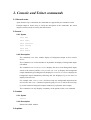
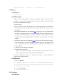
2.2.2 Description
The command event show enables display of background output on this console
device.
The command event unshow disables it. By default, the display of background output
is disabled.
The command event recent (or event r) displays the most recent background output
stored in the memory buffer; event previous (or event p) displays the background
output immediately preceding that last displayed; event next (or event n) displays the
background output immediately following that last displayed. Up to 24 lines are
displayed in each case.
For example, after event r, event n will show only new background output that has
arrived since the event r command: repeated typing of event n will let the user keep
up to date with new background output (without any repetitions in the output).
The command event help displays a summary of the options of the event command.
2.3 restart
2.3.1 Syntax
restart
2.3.2 Description
Reboots the ADSL modem.
2.4 uptime
2.4.1 Syntax
uptime
2.4.2 Description
Displays the time for which the system has been up.
2.5 version
2.5.1 Syntax
version
2.5.2 Description
Displays the system type and version.
2.6 <process>, <process> <command>
2.6.1 Syntax
<process> <command>
<process>
home
home <command>
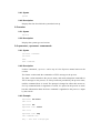
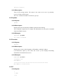
2.6.2 Description
In these commands, <process> can be any of a list of process names known to the
console.
The former variant sends the command as a TELL message to the process.
The latter variant remembers the process name, and sends subsequent commands as
TELL messages to the process, as if they had been preceded by the process name,
until the command home is issued. The prompt is changed to reflect this; moreover,
if a help command with no arguments is issued, it is passed to the process as usual,
but then information about the home command is appended to the process’s output
by the console.
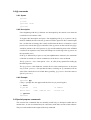
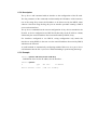
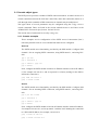
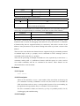
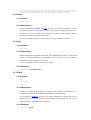
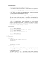
2.6.3 Example
mymachine> isfs version
ISFS v2.07
mymachine> isfs
mymachine isfs> version
ISFS v2.07
mymachine isfs> help
ISFS commands are:
help - this text is displayed
ls - list ISFS files
rm <file> - remove file from ISFS
cat <file> - show file contents
version - displays version number
Use “home” to return to “mymachine>” prompt
mymachine isfs> home
mymachine>
When the console is at the prompt of a particular process, the command home
<command> or home <process> <command> may be used to execute a command
as if the user had typed home followed by <command> or <process> <command>.
However, the console will remain at the same process prompt.
The command home <process> will change the prompt from the current process to a
new process <process>.
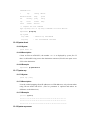
2.6.4 Example
mymachine> bridge
mymachine bridge> version
Bridge Version 1.15
mymachine bridge> home version
Modem BD3000 Version 7.0.0.7 (2 Jun 2000)
mymachine bridge> home nat version
NAT Version 2.02
mymachine bridge> home edd
mymachine edd> version
EDD Version 1.03
mymachine edd> home
mymachine>
2.7 . (history mechanism)
2.7.1 Syntax
.
2.7.2 Description
Repeats the previous console command.
2.7.3 Example
mymachine> isfs version
ISFS v2.07
mymachine> .
ISFS v2.07
2.8 @ commands
2.8.1 Syntax
@@<line>
@ <line>
@<process> <line>
@<process>
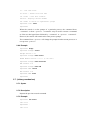
2.8.2 Description
Lines beginning with the @ character are intercepted by the console even when the
console device is bound to a file.
To bypass this interception and pass a line beginning with @ to a process, the @
must be doubled; the line with one @ removed will be passed on like a normal input
line. (At the time of writing, this is most useful when the device is bound to a slotN
process on a switch; then @ip would refer to the ip process on the switch, but @@ip
would be passed to the slotN process as @ip and forwarded by that to the ATMOS
console on an expansion card, which will interpret it as referring to the ip process on
the expansion card.)
If the @ is followed by a space (or any non-alphanumeric character), the remainder
of the line is treated as a console command, as if the device were not bound.
The @<process> <line> form passes <line> to a file (if any) opened for reading by
the named process.
The @<process> form binds the console device to the named process, in the same
way as bind <process>. (Except that the latter, not being an @ command, will not
work if the console device is bound. More generally, @<process> does the same as
@bind <process>.)
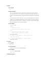
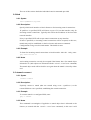
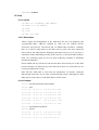
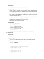
2.8.3 Example
mymachine> @ip
(The ip> prompt does not appear until the Enter key is pressed again.)
ip> device
# type dev
file
IP address
device ether
ether //edd mtu 1500
192.168.3.55
ip> @console
mymachine>
2.9 Special-purpose commands
This section lists commands that are normally useful only to developers rather than to
normal users, or else are retained only for consistency with older versions of the software.
They are not described in the output of the help command.
2.10 list
2.10.1 Syntax
list
2.10.2 Description
The list command lists the active console devices (referred to as threads) and files.
For each console device, if it is bound to a file then the list shows which file it is
bound to; if background output is enabled on that device then the list indicates the
fact.
For each file, the list shows the name of the process that opened the file and the
number of read commands outstanding on the file. If the file is bound to a device
then the list shows which device it is bound to; if the file is for foreground output
then the list indicates the fact (with the string FG).
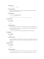
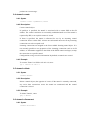
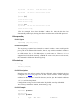
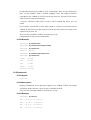
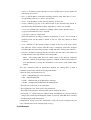
2.10.3 Example
mymachine> list
Threads:
1: ACTIVE, FP 00730520
3: ACTIVE, FP 00719170, Bound 75, events shown
Files:
0: OPEN FP 00718e70, Queue chips, 0 read(s)
1: OPEN FP 00718c30, Queue isfs, 0 read(s)
(some output omitted)
49: OPEN FP 00715af4, Queue ip, 0 read(s), Bound 3, FG
(some output omitted)
75: OPEN FP 00715b38, Queue ip, 1 read(s), Bound 3
(some output omitted)
2.11 echo …
2.11.1 Syntax
echo <text>
2.11.2 Description
Echoes the text. (Not a very useful command.)
2.11.3 Example
mymachine> echo hello world
hello world
2.12 tell <process> …
2.12.1 Syntax
tell <process> <command>
2.12.2 Description
Sends the command as a TELL message to a specific process. Note that for many
processes the tell can be omitted.
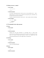
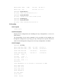
2.12.3 Example
mymachine> tell hswctrl portinfo a1
port type vers flags
A1 25Mbps 1QUA mast uni30 ilmi netside tx8khz manconfig
2.13 exit, exit!
2.13.1 Syntax
exit
exit!
2.13.2 Description
Exits from application firmware to the boot ROM. Without the exclamation mark,
the command works only from the serial interface; with the exclamation mark it
works from any console device.
Note - This command is now deprecated and provides no useful output.
2.14 debug
2.14.1 Syntax
debug
2.14.2 Description
Enters the debugger. Only works when issued at the serial interface. (Since the
debugger talks to the serial interface, the debug command would be of little use
elsewhere.)
2.15 crlf, nocrlf
2.15.1 Syntax
crlf
nocrlf
2.15.2 Description
Controls whether line-feed characters written to this console device are output as
carriage-return/line-feed pairs (crlf) or just as single line-feed characters (nocrlf).
2.16 bind <process>, unbind
2.16.1 Syntax
bind <process>
unbind
2.16.2 Description
The former command binds this console device to the specified process – that is,
binds this device to the file, if any, opened for read by that process, and binds every
file opened by the process to this device.
The latter command unbinds this console device – that is, undoes the above bindings.
2.16.3 Example
mymachine> bind ip
ip> @ unbind
mymachine>
2.17 Commands for the chips process
2.18 cpu
2.18.1 Syntax
cpu
2.18.2 Description
Displays the recent CPU utilization as a percentage. This is a fairly crude
measurement: the ATMOS kernel measures the time that the CPU spends in the idle
loop over successive three-second intervals, and the cpu command uses this
measurement from the most recent complete three-second interval.
2.19 debug
2.19.1 Syntax
debug
2.19.2 Description
Enters the ATMOS debugger.
2.20 exit
2.20.1 Syntax
exit
2.20.2 Description
Exits from ATMOS to the boot ROM.
Note - This command is now deprecated and provides no useful output.
2.21 help
2.21.1 Syntax
help
?
help <command>
2.21.2 Description
The help command lists all chips commands. ? is a synonym for this command;
help <command> displays more detailed help on the specified command.
This command is available only if the pre-processor symbol CHIPSHELP is defined.
2.22 info
2.22.1 Syntax
info
2.22.2 Description
Displays system type and version number, and the MAC addresses.
2.23 mem
2.23.1 Syntax
mem
2.23.2 Description
Displays a summary of how much memory is used by each process (distinguishing
between heap and thread stacks, along with some other minor categories), along with
the amount of free heap memory and the size of the largest single free block.
2.24 rb, rh, rw, wb, wh, ww
2.24.1 Syntax
rb <addr>
rh <addr>
rw <addr>
wb <addr> <val>
wh <addr> <val>
ww <addr> <val>
2.24.2 Description
Reads the byte (rb), word (rw) or half-word (rh) at a specified address, or writes a
specified value to the byte (wb), word (ww) or half-word (wh). Addresses and values
are specified in hexadecimal, with an optional 0x prefix.
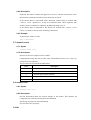
2.24.3 Example
> rw 1c4b54
word at 0x001C4B54 contains 0x0000337E
> rb 1c4b55
byte at 0x001C4B55 contains 0x33
> wb 1c4b56 0x20
value 0x20 written to byte at 0x001C4B56
> rw 1c4b54
word at 0x001C4B54 contains 0x0020337E
> ww 0x1c4b54 14c44
value 0x00014C44 written to word at 0x001C4B54
>
2.25 steal
2.25.1 Syntax
steal memory use <handle> <amount>
steal memory release <handle>
steal file use <handle> <device>
steal file release <handle>
steal cpu use <percentage>
steal cpu release
steal status [memory] [file] [cpu]
2.25.2 Description
Uses up heap memory, file handles, or CPU cycles. <handle> is a number from 0 to
19, used to identify the resource for a later steal … release command.
This command is intended to help test system behaviour when resources are limited,
and is available only if the pre-processor symbol CHIPS_STEAL is defined.
2.26 tell
2.26.1 Syntax
tell <process> <command>
2.26.2 Description
Sends the command as a TELL message to a specific process. (The same as the
console tell command.)
3. Bridge Console commands
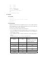
3.1 device add
3.1.1 Syntax
device add <device>
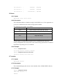
3.1.2 Description
This command adds a device to the bridge configuration. Attempts to add the bridge
itself or an existing device to the bridge are rejected.
Attempts to add devices which don’t support the Cyan interface are rejected. There
is a limit on the number of devices that can be attached to the bridge. If the device
being added is from a process which supports multiple devices, the /DEVICE
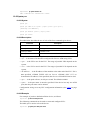
attribute must be specified as part of the device name. The table below shows
devices which may be attached to the bridge, although not all systems may support
all devices.
Device
Remarks
Source
Edd
Ethernet driver
bun_ethernet
r1483
RFC1483 protocol (PVC)
rfc1483
Ppp
Point-to-Point protocol
pp
Configuration saving saves this information. See the section entitled Implementation
Constraints in the ATMOS Transparent Bridge Specification, DO-007087-PS, for
details of which devices are added by default.
3.1.3 Example
Simple examples
device add edd
device add ppp/DEVICE=2
Using the BUN RFC1483 driver
This example shows how to add the BUN RFC1483 driver, dynamically from the
console. You need to define and configure a device and a port.
Normally, the RFC1483 BUN device will pass all data straight through, untouched.
This means that even though you have changed your port definition to include the
RFC1483 driver, you can still use other protocols on the same port. In order to
enable RFC1483 encapsulation, the RFC1483 attribute on the channel must be set to
true.
The channel attribute mode dictates the functional behaviour of the driver, in terms
of encapsulation method to use and traffic nature (bridged/routed). The channel
attribute promiscuous selects the promiscuity behaviour of the driver.
The driver requires, at configuration time, to be layered with the BUN utopia and
nec98408 devices, in order to be used. So, for the sake of the following examples,
let's assume that the related BUN port is called rfc_port, and it has been configured
in the following way:
device: rfc_dev = rfc1483, nec98408, utopia
port : rfc_port = rfc_dev/PhysicalPort=0/PortSpeed=59111
If we want to attach the device to the bridge, then the following command must be
issued (all typed on one line):
bridge device add //bun/port=rfc_port/rfc1483=true
/mode=llcbridged/txvci=600/rxvci=600
The above command creates a channel with RFC1483 enabled, and it uses the LLC
encapsulation for bridged traffic. The next command, is the same, however it uses
the VC multiplexing method:
<all typed in one line>
bridge device add //bun/port=rfc_port/rfc1483=true
/mode=vcmuxbridged/txvci=600/rxvci=600
3.1.4 See also
device delete on page 38 and device list on page 39.
3.2 device delete
3.2.1 Syntax
device delete <device>
3.2.2 Description
This command deletes a device from the bridge configuration. The syntax of the
device name is the same as that for the device add command.
Configuration saving saves this information.
3.2.3 Example
device delete r1483
3.2.4 See also
device add on page 36 and device list on page 39.
3.3 device list
3.3.1 Syntax
device list
3.3.2 Description
This command lists all the devices that are currently attached to the bridge. It does
not show the stored configuration (which can be seen with the config print
command).
3.3.3 Example
device list
3.3.4 See also
device add on page 36 and device delete on page 38.
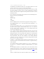
3.4 ethertype
3.4.1 Syntax
ethertype [<port> any|ip|pppoe]
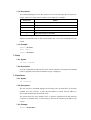
3.4.2 Description
This command enables filtering of Ethernet packets according to the ETHER_TYPE
field in the header. Only packets of the type specified using this command will be
sent on the port specified; packets of all types will always be received.
By default, all bridge ports are set to any, which means that the type of the packet
will never be checked. The meaning of the other options is as follows:
Option
Permitted ETHER_TYPE values
ip
0x0800 - IP
0x0806 - ARP
pppoe
0x8863, 0x8864 - PPP Over Ethernet (RFC 2516)
The port is specified as an integer, as displayed by the device list command. When
using this command in the initbridge configuration file, ports are numbered in the
order in which the device add commands are given, starting from 1.
If no arguments are given, the current settings for each port are displayed.
3.4.3 Example
ethertype 2 any
3.5 filter
3.5.1 Syntax
filter
3.5.2 Description
This command shows the current contents of the bridge’s filter table. The MAC
entries for each device are shown in turn together with the time that the MAC
address was last seen by the bridge. The command also shows the current filter
ageing time, in seconds, and the number of creation failures since the system was
started. Creation failures occur when there is no room left in the filter table for a new
entry.
3.5.3 Example
filter
3.6 filterage
3.6.1 Syntax
filterage [<age>]
3.6.2 Description
This command sets, or displays if no arguments are given, the filter table ageing time.
The ageing time is the time after which MAC addresses are removed from the filter
table when there has been no activity. The time is specified in seconds and may be
any integer value in the range 10…100,000 seconds. This value may also be changed
through SNMP. Changing the value of filterage has immediate effect.
Configuration saving saves this information. By default, the filter ageing time is set
to 300 seconds.
3.6.3 Example
filterage
3.7 flush
3.7.1 Syntax
flush [<port>]
3.7.2 Description
This command allows the MAC entries for a specified port, or all ports, to be
removed from the filter table. The port number for a device may be determined using
the device list or status commands. If the port number is omitted, all entries for all
ports are removed from the filter table.
3.7.3 Example
flush
3.8 info
3.8.1 Syntax
info
3.8.2 Description
This command displays build information about the bridge process. The version
command is a synonym for this command.
3.8.3 Example
info
3.9 interface
3.9.1 Syntax
interface [sub-command]
3.9.2 Description
This command accesses the ethernet support library sub-commands for the bridge
itself, not for the devices which are attached to it.
It is not described here.
3.9.3 Example
interface stats
3.10 portfilter
3.10.1 Syntax
portfilter [<source port> all|<destination ports>]
3.10.2 Description
The portfilter command allows control over the bridge’s forwarding and
broadcasting behaviour. By default, when a multicast or an unknown packet is
received on a port (referred to above as the source port), it will be forwarded to all
other bridge ports (referred to above as the destination ports).
Each bridge port may have its behaviour modified separately. The first example
below configures the bridge so that packets arriving on port 2 will only be forwarded
to ports 3, 4 and 5, and packets arriving on port 3 will only be forwarded to port 1.
All other ports retain their default behaviour.
Note that this command does not force packets arriving on the source port to be sent
to all specified destination ports. The bridge retains its learning behaviour, so unicast
packets, once their destination is known to the bridge, will still only be sent to one
port. Note also that the bridge itself (for example when attached to the IP router) will
always forward to all ports, and will always be forwarded to by all ports.
The default behaviour can be restored by calling this command with the argument all,
as shown in the second example.
The ports are specified as integers, as displayed by the device list command. When
using this command in the initbridge configuration file, ports are numbered in the
order in which the device add commands are given, starting from 1.
If no arguments are given, the current settings for each port are displayed.
3.10.3 Example 1
portfilter 2 3 4 5
portfilter 3 1
3.10.4 Example 2:
portfilter 2 all
portfilter 3 all
3.11 spanning
3.11.1 Syntax
spanning [sub-command]
3.11.2 Description
The spanning tree commands are only available if it has been compiled in to the
bridge.
The spanning tree commands are documented in the ATMOS Spanning Tree
Specification, DO-007085-PS.
3.12 status
3.12.1 Syntax
status
3.12.2 Description
This command shows the status of the bridge and its ports. The status information
for a port includes the SNMP type information about time-exceeded packets, packets
discarded, etc. It also includes the broadcast history of the port over the last five
seconds and the high water mark of packets queued on the bridge for this device.
3.12.3 Example
status
3.13 version
3.13.1 Syntax
version
3.13.2 Description
This command displays build information about the bridge process. The info
command is a synonym.
3.13.3 Example
version
4. BUN Console commands
4.1 Introduction
4.1.1 Scope
A description is provided of the use of console commands.
No information on implementing additional commands is given in this chapter:
implementers of new BUN devices may provide access to diagnostic or status
information by implementing attributes to handle these tasks. The standard BUN
console commands may then be used to display or change these settings.
All BUN process commands may be issued by posting TELL messages to the BUN
process. The BUN process does not support the used of STDIN command streams.
(Refer to tell <process> … on page 19 for more information on the TELL command
interface.)
Command parsing is case insensitive. White-space may be used to separate distinct
arguments. Any prefix of the string bun to the command line is ignored.
4.1.2 Build Inclusion
The full BUN console command set is included with all builds that include the BUN
package.
To include the BUN package, add the following directive to the ATMOS SYSTEM
file:
package bun
The directive may be placed anywhere in the SYSTEM file after the inclusion of the
core package (core.pkg).
4.1.3 Compile Time Configuration
Most BUN commands are available irrespective of the compilation options. This
section describes exceptions to this rule.
build
The build command displays the compile-time options, and so will change according
to what compilation options are used…
Any compile option that affects BUN operation should be displayed by this
command.
4.1.4 Command arguments
devicename
The name of a device.
Device names are either implicit (ie.: provided from the compiled-in device code) or
explicit (ie.: from a device: configuration request).
Device names may contain upper or lower case letters, but use case insensitive
matching.
portname
The name of a port. This can take several forms:
• The name given on the port configuration request
• The alias name specified in the port's Alias attribute
• The name as a <class>:<instance> pair. For example, atm:0 to reference the first
port supporting ATM cell traffic.
• The BUN port number. For example, 0 to refer to the first port.
The last option may be dropped in a future software release.
Port names may contain upper or lower case letters, but all name matching is case
insensitive.
channelnumber
The number of a channel. Within a port, each available channel is identified within
BUN by a unique channel number. Channel numbers are positive integers, assigned
from zero upwards.
To determine the channel numbers that are currently in use, use the list channels
command to show all active channels on a port (or ports).
Note that to be uniquely specified, both a port name and channel number must be
given to console commands which display or manipulate channels.
classname
The name of a class.
Class names may contain upper or lower case letters, though class name matching is
always case insensitive.
By default, BUN provides the following class definitions:
• all: All ports in the system
• atm: All ports supporting ATM cell traffic
• adsl: All ports using the ADSL hardware interface
• ethernet: All ports using an ethernet hardware interface
• hdlc: All ports using an HDLC hardware interface
• pci: All ports using a PCI hardware interface
• usb: All ports using a USB hardware interface
A running system may contain additional classes specified via the class
configuration directive (see the commands list classes on page 62 and list config on
page 59).
If necessary, commands may be quoted using angle brackets or double quotes. This
prevents the stripping of white-space from the input line.
For example:
set port atm/usercomment="This is a comment string"
set port atm/usercommand=<An alternative syntax>
Within either form of quoted section, the corresponding close quote character may
be embedded by prefixing with a backslash. So you could write:
set port atm/usercomment=<This is a "cell based" port>
set port atm/usercomment="This is a \"cell based\" port>
Mostly you probably won't need to worry about quotation, but be aware of it's effects
if you do.
The remainder of this section describes the commands themselves.
4.2 help
4.2.1 Syntax
help [<command>]
4.2.2 Description
Display command information.
If used without the optional command name, a summary of the commands available
will be displayed.
If used with a command name, brief usage information will be shown for the
command.
Note: Commands listed but which are not covered by this documentation are
not supported, and may not be present in future software releases.
4.2.3 Examples
help
help set port
Note: This command is not intended to replace this documentation, and
provides only a very basic level of detail.
4.3 version
4.3.1 Syntax
version
4.3.2 Description
Display the BUN software version.
4.3.3 Example
version
4.4 build
4.4.1 Syntax
build
4.4.2 Description
Display information about compile-time build options. For example, if tracing or
debug code has been compiled into the image.
4.4.3 Example
build
4.5 config
4.5.1 Syntax
config <configurationstring>
4.5.2 Description
Issue a configuration request to BUN.
This command can be used to pass arbitrary configuration strings to BUN,
effectively calling bun_ConfigMakeRequest() with the supplied configuration string.
This may be used to create new devices or ports at run time, using the same syntax
as the configuration strings in the SYSTEM file BUN_CONFIG_<n> directives.
This can be particularly useful during the development of new software.
4.5.3 Example
config device : nuclear = detonator, uranium
config port : launch = nuclear/silo=3
This can also be written as simply:
device : nuclear = detonator, uranium
port : launch = nuclear/silo=3
4.6 list config
4.6.1 Syntax
list config
4.6.2 Description
List the configuration requests that have been passed to BUN.
BUN records all configuration requests that are issued, and maintains information
about their parsing. Configuration requests can be in one of three states:
• Completed – the request has completed successfully
• Stalled – the request is stalled, pending creation of a (as yet) non-existent device
• Failed – the request failed
Each request is displayed together with any relevant information. In the case of
failed requests, an error code is given and the point at which parsing of the
configuration string failed is highlighted.
Stalled requests can be unblocked by creating a new device with suitable properties
by using the BUN config console command to issue a device configuration request.
This command is extremely useful for diagnosing problems with device or port
configuration.
4.6.3 Example
list config
4.7 list devices
4.7.1 Syntax
list devices
4.7.2 Description
List all available devices.
This will show all devices, regardless of how they were created. This includes
devices which were compiled into the system (such as the utopia device), and
compound devices which were created by configuration requests (such as the atm25
device, a compound of the utopia and nec98408 devices).
4.7.3 Example
list devices
4.8 show device
4.8.1 Syntax
show device <devicename>
4.8.2 Description
Display information about at device.
This displays information about a device in the following format:
Name:<devicename>
Description<devicedescription>
Contains:<devicelist>
The device name is the root name of the device. This is the same as the name passed
to the show device command.
The device description is a brief string describing the device. For compiled in
devices, this string is provided by the driver code. For compound devices, this string
is the configuration request used to create the device.
The device list shows which driver code is invoked by this device. For a compiled in
device, this will just be the device itself. For a compound device, this will be the list
of devices linked to form the compound driver.
4.8.3 Example
show device utopia
show device atm25
4.9 list classes
4.9.1 Syntax
list classes
4.9.2 Description
List available port classes on the console. The class name is displayed, together with
the necessary attributes for a port to be a member of said class.
4.9.3 Example
list classes
4.10 show class
4.10.1 Syntax
class <classname>
4.10.2 Description
List members of the specified port class.
4.10.3 Example
show class atm
4.11 list ports
4.11.1 Syntax
ports
4.11.2 Description
List all available ports on the console, in the following format:
<portnumber> : <portname>
All BUN console which require a port to be identified can accept either the port
number or port name as an argument. They may also be used as the argument to a
/port= attribute in fopen() strings.
4.11.3 Example
ports
4.12 show port
4.12.1 Syntax
port <portname>
4.12.2 Description
Display detailed information about a port.
This command enumerates all attributes for a port and displays them on the console.
It is useful to determine the properties of a port.
4.12.3 Example
port atm
4.13 set port
4.13.1 Syntax
set port <portname> / <attributelist>
4.13.2 Description
Modify a port attribute.
This command may be used to modify an attribute on a port, overriding any values
specified in the original port configuration request. The effects of changing any such
attributes are device dependent.
This command is intended for development purposes only.
4.13.3 Example
set port atm /usercomment=”An ATM network port”
4.14 list channels
4.14.1 Syntax
list channels [<portname> ]
4.14.2 Description
List all open connections on the specified port. If no portname is specified, all
channels on all ports will be displayed.
The channels are shown with their identification number and a selection of useful
attributes. A full attribute list can be obtained via the show channel command.
All channels are shown with the Enabled attribute first, which indicates if the
channel has yet been enabled (connected) by the application code.
4.14.3 Examples:
list channels 0
list channels atm:0
4.15 list all open channels
4.15.1 Syntax
list all open channels [<portname> ]
4.15.2 Description
This command is similar to the list channels command. The list channels command
shows channels which are either enabled or open. The list all open channels
command only shows channels which are open.
If no portname is specified, all channels on all ports will be displayed.
The channels are shown with their identification number and a selection of useful
attributes. A full attribute list can be obtained via the show channel command.
4.16 show channel
4.16.1 Syntax
show channel <portname> <channelnumber>
4.16.2 Description
Display information about the specified channel. The channel identification number
may be obtained from the list channels command. All attribute values for the
channel are displayed on the console.
Note that you must specify both a port name and channel number. Channel numbers
are only unique within a given port.
Also note that, unlike the old ATM driver, the channel number is not the same as the
receive VCI number.
It is also possible to display channels that are not currently opened by an application.
The bun.active attribute will return true if a channel is currently open, else false.
Note that a channel handle may be closed and then re-opened by an application at
any time – be cautious when using this command.
4.16.3 Example
show channel atm 0
4.17 set channel
4.17.1 Syntax
set channel <portname> <channelnumber> / <attributelist>
4.17.2 Description
Modify attributes on the specified channel.
This command allows you to change the attribute values for a given channel. The
effect of any changes will be device dependent.
Use this command with extreme caution. The same warnings about an application
closing and reopening a channel handle apply as they do for the show channel
command. Also beware that the application will not be explicitly notified of any
changes made, though if it queries its own attribute data it will pick up any changes
that have been made.
This command is intended for development purposes only.
4.17.3 Example
set channel atm 27 /txvci=32/rxvci=32/pcr=1234
4.18 reset port
4.18.1 Syntax
reset port <portname>
4.18.2 Description
Re-initialise port hardware.
This may be used to request that a device re-initialise the underlying hardware. Not
all devices implement this command.
This command is primarily intended for use during test and development of new
hardware devices.
4.18.3 Example
reset port 3
5. DHCP-client Console commands
5.1 config
5.1.1 Syntax
dhcpclient config
5.1.2 Description
This command displays the current configuration of the DHCP client, including
selected DHCP options.
5.1.3 Example
bd3000> dhcpclient config
--DHCP client configuration file: ‘//isfs/dhclient.conf’
timeout 60;
retry 60;
reboot 10;
backoff-cutoff 40;
interface “ethernet” {
send dhcp-lease-time 5000;
send dhcp-client-identifier “Galapagos”;
}
5.2 help
5.2.1 Syntax
dhcpclient help <command|all>
5.2.2 Description
This command provides help on the various console commands provided by the
ATMOS DHCP client. Specifying the command name gives detailed help, and
specifying the argument all gives detailed help on all commands.
5.2.3 Example
bd3000> dhcpclient help
Help is available on the following commands:
Config
help
pool
status
trace
untrace
5.3 pool
5.3.1 Syntax
dhcpclient pool [verbose]
5.3.2 Description
This command displays the state of the memory pool being used by the DHCP client.
Should the client ever run out of memory, use of this command is helpful in
determining the optimum memory pool size for the client. For example, supporting
DHCP client functionality on several interfaces simultaneously will require
proportionately more memory. The default pool size specified in the system file
dhcpclient is 40000 bytes.
The verbose option lists all allocated and freed memory chunks.
5.3.3 Example
bd3000> dhcpclient pool
DHCP Client Memory Pool Status
total pool size
39968
free
21392
allocated
18576
mean alloc chunk
67
max free chunk
13904
5.4 status
5.4.1 Syntax
dhcpclient status [all]
5.4.2 Description
This command provides DHCP status information for the active bound lease
associated with each valid interface in turn, including IP address, time until lease
renewal, subnet mask and DHCP server address. Including the all option shows, for
each valid interface, the active lease, leases which are being, or have been offered to
the interface, and any leases which are still being held by the client which are not
currently active (since a single interface can only have one active lease at a time).
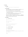
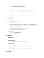
5.4.3 Example
bd3000> dhcpclient status
DHCP Client Lease Status (active lease only)
Interface 'ethernet'
Status
|
Server ID
|
IP address
|
Subnet mask
| Renewal
----------+-----------------+----------------+-----------------+----------*ACTIVE* | 192.168.219.151 | 192.168.219.1 |
255.255.255.0 | 31 seconds
---------------------------------------------------------------------------
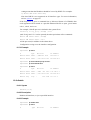
5.5 trace
5.5.1 Syntax
dhcpclient trace <trace option>
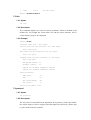
5.5.2 Description
This command enables or disables tracing for the DHCP client. If no arguments are
given the command lists the current tracing options enabled.
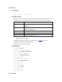
The following trace options are available:
Option
Description
lease
Report changes in lease status (any interface)
bootp
Report changes in lease status (any interface)
error
Report all errors (fatal events)
Warn
Report “warn” level events (important events)
Note
Report “note” level events (minor/frequent events)
All
All trace options
Tracing options are disabled by using the untrace command with the option names
to be disabled.
Saving configuration does not preserve the current tracing options that are enabled.
By default tracing of error, warn and note are enabled.
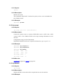
5.5.3 Example
bd3000> dhcpclient trace
No tracing options currently enabled.
bd3000> dhcpclient trace error warn note
Currently tracing: error warn note
5.6 DHCP-related IP process commands
The following commands are not provided by the DHCP client process but by the IP
process ip (For more information, see DO-007285-PS, ATMOS TCP/IP Functional
Specification.)
5.7 ip device
5.7.1 Syntax
ip device add <i/f> <type> <file> [mtu <size>] [<IP address>|dhcp]
ip device
5.7.2 Description
The ip device add command adds an interface to the configuration of the IP stack.
The last parameter of the command would normally the IP address of the interface;
use of the string dhcp causes the IP address to be discovered by the DHCP client
software. Note that using the flag dhcp on an interface precludes running a DHCP
server on that interface!
The ip device command lists the current configuration of any devices attached to the
IP stack. A device configured to use DHCP will show dhcp in the IP address column,
followed by the actual IP address discovered and bound by DHCP, if any.
For interfaces configured to use DHCP, saving configuration only marks the
interface as using DHCP; it does not save the actual IP address discovered by DHCP,
which must be renewed.
A useful method of automatically configuring suitable IP devices is to put a device
add statement into the file //isfs/resolve and downloading it upon booting the image.
5.7.3 Example
bd3000> ip device add ethernet ether //edd dhcp
…DHCP then discovers the IP address for the interface…
bd3000> ip device
#
type
device ethernet
ether
dev file
//edd
IP address
mtu 1500dhcp
6. DHCP-server Console
commands
This chapter describes the DHCP-server Console commands.
6.1 config
6.1.1 Syntax
dhcpserver config [add <text>|confirm|delete|flush]
6.1.2 Description
This command displays or edits the current configuration of the DHCP server. To
display current configuration, provide no arguments to the command.
• Use o f the add option adds the line <text> to the configuration file.
• Use o f t he confirm option re-parses the configuration file, confirming the changes
made if the parse is successful.
• Use o f t he delete option deletes the last line from the configuration file.
• Use o f t he flush argument deletes the whole configuration.
Following any change to the configuration file, it is necessary to confirm the
changes, issue a flashfs update command to commit the change to FLASH, and then
restart the system before the changes can take effect.
6.1.3 Example
bd3000> dhcpserver config
--Current DHCP server configuration
--allow unknown-clients;
allow bootp;
subnet 192.168.219.0 netmask 255.255.255.0 {
range 192.168.219.10 192.168.219.30;
max-lease-time 5000;
}
bd3000> dhcpserver config flush
Configuration file flushed.
bd3000> dhcpserver config
--Current DHCP server configuration
(Issue "dhcpserver config confirm" followed by "flashfs update" to confirm
new configuration)
--bd3000>
6.2 help
6.2.1 Syntax
dhcpserver help <command|all>
6.2.2 Description
This command provides help on the various console commands provided by the
ATMOS DHCP server. Specifying a command name gives detailed help on the
command. Specifying all gives detailed help on all available commands.
6.2.3 Example
bd3000> dhcpserver help
Help is available on the following commands:
config
help
pool
status
trace
untrace
6.3 pool
6.3.1 Syntax
dhcpserver pool [verbose]
6.3.2 Description
This command gives a summary of DHCP server memory usage. The verbose option
shows the entire memory allocation/free list.
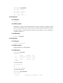
6.3.3 Example
bd3000> dhcpserver pool
DHCP Server Memory Pool Status
total pool size
79968
free
52448
allocated
27520
mean alloc chunk
59
max free chunk
30416
6.4 reset
6.4.1 Syntax
dhcpserver reset
6.4.2 Description
This command prompts the server to do a warm reset of itself. This has the effect of
bringing the server back up as if the system had been rebooted, except that the lease
database is preserved in SDRAM between resets.
Please note, however, you should still save the configuration file to FLASH if you
want the configuration to be preserved upon rebooting the whole system.
The advantage of this command is that it allows configuration changes that have
been confirmed (using config confirm) to take effect immediately, rather than having
to do a flashfs update and restart.
This command is also convenient for defining subnet topologies for IP interfaces that
have been added dynamically.
6.4.3 Example
bd3000> dhcpserver reset
dhcpserver: Reset request acknowledged. Reset imminent.
6.5 status
6.5.1 Syntax
dhcpserver status
6.5.2 Description
This command provides a summary of all leases known to the server on each
interface in turn. It also shows remaining available IP addresses (i.e. those with no
specified lease time, or client identifier).
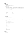
6.5.3 Example
bd3000> dhcpserver status
DHCP Server Lease Status
Interface “ethernet”
IP address
|
Client UID/hw addr
| Expiry
---------------+-----------------------+----------------192.168.219.1
| 01:00:20:af:20:6f:59 | 11 hours
192.168.219.2
| 01:00:20:af:11:2a:ac | 8 hours
192.168.219.3
|
192.168.219.4
| 00:20:af:20:00:2b
| 2 days
192.168.219.5
|
<unknown>
| Never
192.168.219.6
|
<unknown>
| Never
192.168.219.7
|
<unknown>
| Never
Myclient
| 140 seconds
192.168.219.8
|
<unknown>
| Expired
192.168.219.9
|
<unknown>
| Expired
192.168.219.10
|
Foobarbozzle
| Expired
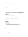
6.6 trace
6.6.1 Syntax
dhcpserver trace <trace option>
6.6.2 Description
This command enables or disables tracing for the DHCP server. If no arguments are
given, the command lists the current tracing options enabled.
The following trace options are available:
Option
Description
lease
Report changes in lease status (any device)
bootp
Report any BOOTP interoperation/emulation
error
Report all errors (fatal events)
warn
Report all warnings
note
Report “note” level events (minor events)
all
All trace options
Tracing options are disabled by using the untrace command in the same way.
Saving configuration does not preserve the current tracing options that are enabled.
By default, only tracing of error is enabled.
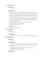
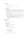
6.6.3 Example
bd3000> dhcpserver trace
No tracing options currently enabled.
bd3000> dhcpserver trace error warn note
Currently tracing: error warn note
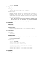
6.7 version
6.7.1 Syntax
dhcpserver version
6.7.2 Description
This command displays the current version number of the ATMOS DHCP software.
6.7.3 Example
bd3000> dhcpserver version
ATMOS DHCP Version 1.07
bd3000>
7. NAT Console commands
This chapter describes the NAT (Network Address Translation) Console
commands.
7.1 event
7.1.1 Syntax
nat event [n]
7.1.2 Description
This command displays or sets the current level of event tracing in the NAT process.
Larger values of n result in more verbose trace output. For example:
Event level
Output
1
Only show fatal errors, eg. lack of system resources
2
Only show important information and problems
3
Show the creation of new sessions
4
Show trace output for discarded packets
5
Show trace output for all packets
All trace messages are printed as background output, and therefore will not be
displayed asynchronously on the console unless the event show command has been
issued.
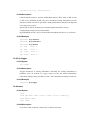
7.1.3 Example
bd3000> nat event
Event level: 1
bd3000> nat event 2
7.2 help
7.2.1 Syntax
nat help [command]
7.2.2 Description
Lists the commands provided by the NAT console interface. If an optional command
name is supplied, help on that command’s usage is displayed.
7.3 interfaces
7.3.1 Syntax
nat interfaces
7.3.2 Description
The nat interfaces command displays the IP router ports on which NAT is currently
enabled. For each of these, a status and IP address is listed. The IP address is
discovered automatically from the IP stack.
The status shows the user whether NAT is currently operational on that interface
(enabled), or whether NAT is still waiting to find out the interface’s IP address (not
ready).
7.3.3 Example
bd3000> nat interfaces
Name
Status
IP address
Ethernet
enabled
194.129.40.2
pppnot
ready
–
7.4 inbound
7.4.1 Syntax
nat inbound list
nat inbound add <i/f> <port>/<proto> <new IP> [quiet]
nat inbound delete <#>
nat inbound flush
7.4.2 Description
This command enables the user to list or to set up a series of rules, to determine what
happens to incoming traffic. By default all incoming packets, other that packets
arriving in response to outgoing traffic, will be rejected.
The nat inbound add command allows packets arriving on a specific port and IP
protocol to be forwarded to a machine on the private network.
• <i/f> is an interface name as shown by the nat interface list command;
• <port> is the destination UDP or TCP port number to match in the incoming
traffic;
• <proto> is the IP protocol, either udp or tcp;
• <new IP> is the new IP address on the private network which the packet’s
destination IP address should be translated to.
If a rule is added for an interface on which NAT is not enabled, the rule is added
anyway but a warning is printed to alert the user to this fact. quiet is a special option
which should not normally be issued at the console, and causes this warning to be
suppressed. The quiet option is automatically added by NAT to when writing its
configuration to flash; this is because when a system boots, the NAT process reads in
these rules before IP has registered any interfaces.
nat inbound list shows the current rules for inbound traffic, including all the
arguments passed to the nat inbound add command.
nat inbound delete removes a rule, where <#> is the rule number as shown by the nat
inbound list command.
nat inbound flush removes all the rules.
7.4.3 Example
bd3000> nat inbound add ethernet 80/TCP 192.168.219.38
bd3000> nat inbound list
#
Interface
1
ethernet
Port/Proto
80/tcp
New IP address
192.168.219.38
2
r1483
21/tcp
192.168.219.40
bd3000> nat inbound delete 2
7.5 info
7.5.1 Syntax
nat info
7.5.2 Description
This command displays the values of various parameters which are defined in the
module file, for example the session table size and the session timeouts. NAT’s
current memory usage is also displayed.
7.5.3 Example
bd3000> nat info
Interface table size 1 (116 bytes)
Session table size per interface: 128 (6656 bytes)
Total: 6656 bytes
Hash table size per interface: 128 (512 bytes)
Total: 512 bytes
Fragment table size per interface: 32 (640 bytes)
Total: 640 bytes
Max queued buffers: 16
Fragment timeout:
30
Support for incoming fragments: enabled
Support for outgoing fragments: enabled
Session timeouts:
ICMP query:
10
UDP:
30
TCP (established):
300
TCP (other):
15
Initial port number: 10000
7.6 protocol
7.6.1 Syntax
nat protocols
7.6.2 Description
The nat protocols command lists the application level gateways (ALGs) provided in
the current image in order to support particular higher-level protocols, and the port
or ports which each ALG monitors.
7.6.3 Example
bd3000> nat protocols
Name
Port/IP protocol
ftp
21/tcp
7.7 sessions
7.7.1 Syntax
nat sessions <i/f> [all | summary]
7.7.2 Description
The nat sessions command displays a list of currently active NAT sessions on the
interface <i/f>. In this context, a session is a pair of source IP addresses and port
numbers (and corresponding new port number) that NAT regards as one side of an
active connection. For each TCP or UDP session active, the source and destination
IP address and port number, and the local port number and the age of the session, are
printed.
The all option causes the sessions command to print out information on every
session, including sessions which have timed out. Normally the sessions command
only shows active sessions (those which have not timed out).
The summary command does not show detailed information on each session, but
only prints out the total number of active, timed out and available sessions.
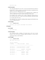
7.7.3 Example
bd3000> nat sessions ppp
Proto Age
NAT port
Private address/port
Public address/port
TCP 34
1024
192.168.219.38/3562
194.129.50.6/21
TCP 10
1025
192.168.219.64/2135
185.45.30.30/80
Total:
2 sessions active
101 sessions timed out
126 sessions available
7.8 stats
7.8.1 Syntax
nat stats <i/f> [reset]
7.8.2 Description
This command displays various statistics gathered by NAT on the interface <i/f>.
These are cumulative totals since power on, or since the reset keyword was given.
The nat stats command does not provide the total number of packets or bytes
transferred, as this information is normally available from the device driver on the
interface which NAT is filtering.
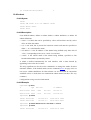
7.8.3 Example
bd3000> nat stats ethernet
Outgoing TCP sessions created:
456
Outgoing UDP sessions created:
123
Outgoing ICMP query sessions:
12
Outgoing ICMP errors:
0
Incoming ICMP errors:
6
Incoming connections refused:
2
Sessions deleted early:
0
Fragments currently queued:
0
7.9 version
7.9.1 Syntax
nat version
7.9.2 Description
This command displays NAT’s internal version number.
7.9.3 Example
bd3000> nat version
NAT Version 1.00
7.10 dump
7.10.1 Syntax
nat dump on|off
7.10.2 Description
This command is only available in debug builds.
nat dump causes a detailed dump of the information in each packet’s header to be
printed both before and after translation. This command is provided for debug
purposes.
7.10.3 Example
bd3000> nat dump on
7.11 fragments
7.11.1 Syntax
nat fragments <i/f name>
7.11.2 Description
This command is only available in debug builds.
nat fragments prints information on the queues in which NAT holds fragmented IP
datagrams, displaying the IP datagram identifier, the number of fragments queued
and a NAT session pointer for each queue. This command is provided for debug
purposes only.
7.11.3 Example
bd3000> nat fragments ether
7.12 hashtable
7.12.1 Syntax
nat hashtable <i/f name>
7.12.2 Description
This command is only available in debug builds.
nat hashtable prints the number of sessions linked to each entry in the hashtable used
to look up outgoing packet on the given interface. This command is provided for
debug purposes only.
7.12.3 Example
bd3000> nat hashtable ethernet
#
Linked sessions
0
1
1
0
2
1
3
2
8. PPP Console commands
This chapter describes the PPP Console commands.
8.1 Console object types
The ppp process presents its setup in terms of a number of distinct object types:
• The upper limit on the number of each of these objects permitted in a system is
configured using the config resource console command.
• The current state of each object is saved by config save.
8.1.1 Channels
The ppp process provides a number of PPP connection channels. A channel is a
single PPP connection. Channels are numbered from 1. Many ppp console
commands affect only a single channel. The command is prefixed with the channel
number.
8.1.2 Users
A user is a user name and password. All users must have distinct names. The user
console command controls these.
8.1.3 Tunnels
A tunnel is a PPTP or L2TP connection. Tunnels are numbered from 1. PPP
channels must be associated with a tunnel to be involved in PPP tunnelling. The
tunnel console command provides control of these.
8.1.4 Interfaces
An interface is an internal MAC (Ethernet) device. PPP channels must be associated
with an interface to be involved with bridging or routing.
8.1.5 Interface 1 and Channel 1
Interface 1 has some special functions associated with it, allowing dynamic IP
address assignment to be performed. Channel 1 is by default associated with
Interface 1. These two should be used only for IP dial-out functions, and for this
function should be attached to the router interface named ppp_device. The dial-out
example in the following section makes this clearer. These specializations have been
made to make the configuration of an IP dial-out simpler.
8.2 Console examples
8.2.1 Simple test
The simplest thing you can do to test ATMOS PPP, between two PPP channels in a
single ATMOS system, is to create a PVC in the switch to which the test box is
connected, between two VCIs (say 32 and 33 here) on the connected switch port.
Type the following:
pvccreate a1 32 a1 33
(at the switch console, if it is a Virata Switch)
ppp event 5
(at the console of the PPP ATMOS system)
ppp 1 pvc 32
ppp 2 pvc 33
ppp 1 enable
ppp 2 enable
(they should now swap packets and synchronise)
ppp 1 status
This should show that the two ends are connected. No data will be exchanged.
8.2.2 IP dial-out over PPP
To perform a dial-out over a PVC, operate as follows:
First set up a router device for PPP to use. No IP address should be specified, so that
the device is created but not enabled. The device name ppp_device should be used.
ip device add ppp_device ether //ppp/DEVICE=1
ppp 1 pvc <whatever>
ppp 1 welogin <name> <password>
ppp 1 enable
If the configuration is saved at this point, the dial-in will be attempted automatically.
8.2.3 IP dial-in server setup
To create a system which can accept dial-in connections over PVCs, type the
following:
Note – For a complex setup such as this, it may be more convenient to create it
on another system using a text editor, then TFTP the setup into the ATMOS
system.
Note – Assume that 8 dial-in PVCs are being created, numbered 32 to 39.
These will be created as channels 2 to 9. A single IP subnet will be created,
attached to a port of the router via interface 3. The IP subnet 192.168.200.0 will
be used, with channel n assigning address 192.168.200.n to the far end. The
server interface will take address 192.168.200.99.
ip device add ppp_device3 ether //ppp/DEVICE=3
192.168.220.99
Further IP setup may be needed, for instance to route the result to some other device
such as the Ethernet port.)
ppp interface 3 localip 192.168.220.99
ppp 2 pvc 32 listen
ppp 2 interface 3
ppp 2 remoteip 192.168.200.2
ppp 2 enable
(and the corresponding setup for each of the channels 3 to 8 as well)
Clients can now dial in to this server, be allocated IP addresses and traffic will be
sent to and from the router.
8.2.4 Remote Bridging
To create a system where two bridges are connected by a PVC, do the following at
each end: (In this example, interface 2 is attached to the bridge in ATMOS (interface
1 is reserved for routed traffic).)
bridge device add ppp/DEVICE=2
(Attach interface 2 to the bridge.)
ppp 1 pvc 32 mac
ppp 1 interface 2
ppp 1 enable
If required, multiple interfaces can be attached to the bridge of a single ATMOS
system so that a single master site is bridged to several satellites. Each incoming
bridging PPP channel should be attached to a distinct interface. Each interface must
be independently attached to the bridge.
8.3 <channel> clear
8.3.1 Syntax
<channel> clear
8.3.2 Description
Clear all aspects of this channel back to their default settings. If there is an active
connection, it is torn down.
8.4 <channel> disable
8.4.1 Syntax
<channel> disable
8.4.2 Description
Clear the enable flag for a PPP channel. This is the default setting. Disabling does
not remove other configured information about this channel.
In the PPP state machine, this sets the PPP link to closed. If it is already closed, there
is no effect.
Configuration saving saves this information. By default, all channels are disabled.
8.5 <channel> discard
8.5.1 Syntax
<channel> discard [<size>]
8.5.2 Description
Discard is a PPP LCP packet type, which is like the Echo packet type but does not
generate a return. This can be used for more careful tests of data transfer on the link,
for instance at sizes near the negotiated MRU.
This command sends an LCP Discard packet, of the specified size. If no size is given,
a minimal sized packet is sent.
Arrival of a Discard packet is logged locally as a level 2 event.
The link must be up and operational in order to do the discard test.
8.6 <channel> echo
8.6.1 Syntax
<channel> echo [<size>]
8.6.2 Description
Echo is an LCP packet, which is used to test an established PPP link. It solicits a
ping-like reply from the far end.
This command sends an LCP Echo packet, of the specified size. If no size is given, a
minimal sized packet is sent. If a size greater than the remote Maximum Receive
Unit size is specified, the value is reduced to the remote MRU before sending.
The command waits for 1 second for a reply packet to arrive, and prints whether the
reply arrived. If a reply arrives subsequent to this, it is logged as a level 2 event.
The link must be up and operational in order to do the echo test.
8.7 <channel> echo every
8.7.1 Syntax
<channel> echo every <seconds>
8.7.2 Description
Echo is an LCP packet, which is used to test an established PPP link. It solicits a
ping-like reply from the far end.
This command sets a channel to confirm the continued presence of an open PPP
connection by sending an LCP echo every few seconds, and requiring an echo reply.
The number of seconds between echo requests is specified as a parameter.
If 0 is specified, the function is disabled. Use the info all command to read the
current state on a channel.
Configuration saving saves this information. By default, the function is disabled.
8.8 <channel> enable
8.8.1 Syntax
<channel> enable
8.8.2 Description
Set the enable flag for a PPP channel. By default, this is disabled.
In the PPP state machine, this flag sets the PPP link to open. If it is already open,
there is no effect.
Configuration saving saves this information. By default, all channels are disabled.
8.9 <channel> event
8.9.1 Syntax
<channel> event [<n>]
8.9.2 Description
Read or set the overall trace output level.
Configuration saving does not save this value. The default event level is 1.
The event levels are shown in the table below:
Level
Description
1
Only very serious errors reported
2
Definite protocol errors or very significant events reported.
3
Links going up/down reported.
4
Every packet and significant state change is reported.
5
Every packet sent/received is disassembled, and hex dumped.
8.10 <channel> hdlc
8.10.1 Syntax
<channel> hdlc [1|0]
8.10.2 Description
If 1, use an HDLC header on the front of transmitted packets and require one on
received ones. This consists of two bytes, FF-03, and assists in interoperability with
some other (non-standard) implementations. If 0, disable this.
Call with no argument to find the current setting.
The default value is 0 (disabled).
Configuration saving saves this information.
If not set, and a packet is received with an HDLC header, the channel goes into a
learned HDLC mode and sends packets with the HDLC header. Thus, interoperation
with HDLC-using equipment should not normally require any configuration.
Learning occurs in this direction only.
Setting hdlc to 0 clears this learned state. Configuration saving does not save the
learned state.
8.11 <channel> info
8.11.1 Syntax
<channel> info [all]
8.11.2 Description
Provide information about the current settings of this channel. This includes all
configured state, and also current protocol information.
Specifying all prints out more information.
info and status are synonyms.
8.12 <channel> interface
8.12.1 Syntax
<channel> interface <n>
8.12.2 Description
Logically associate the specified channel with the specified interface.
Interface 1 is always the router port. It should be used for any PPP channel over
which IPCP communication with the local system’s IP router is desired. Other
interfaces can be created for bridging. A single PPP channel can only be associated
with a single interface, or a single tunnel.
Use info to find the current setting.
Calling with n=0 removes any association. This is the default state.
Configuration saving saves this information.
8.13 <channel> lcpmaxconfigure
8.13.1 Syntax
<channel> lcpmaxconfigure [<n>]
8.13.2 Description
Set the Max-Configure parameter for LCP, as described in Section 4.6 of RFC1661.
This is the maximum number of Configure Requests that will be sent without reply,
before assuming that the peer is unable to respond.
Call with no argument to find the current setting.
The default value is 10.
Configuration saving saves this information.
8.14 <channel> lcpmaxfailure
8.14.1 Syntax
<channel> lcpmaxfailure [<n>]
8.14.2 Description
Set the Max-Failure parameter for LCP, as described in Section 4.6 of RFC1661.
This is the maximum number of consecutive Configure Naks that will be sent before
assuming that parameter negotiation is not converging.
Call with no argument to find the current setting.
The default value is 5.
Configuration saving saves this information.
8.15 <channel> lcpmaxterminate
8.15.1 Syntax
<channel> lcpmaxterminate [<n>]
8.15.2 Description
Set the Max-Terminate parameter for LCP, as described in Section 4.6 of RFC1661.
This is the maximum number of Terminate Requests that will be sent without reply,
before assuming that the peer is unable to respond.
Call with no argument to find the current setting.
The default value is 2.
Configuration saving saves this information.
8.16 <channel> llc
8.16.1 Syntax
<channel> llc [1|0]
8.16.2 Description
If 1, use an LLC header on the front of transmitted packets and require one on
received ones. This consists of four bytes, FE-FE-03-CF, and is required for PPP
Over AAL5 (RFC 2364 p4) when using LLC encapsulated PPP. If 0, disable this.
Call with no argument to find the current setting.
The default value is 0 (disabled).
Configuration saving saves this information.
If not set, and a packet is received with an LLC header, the channel goes into a
learned LLC mode and sends packets with the LLC header. Thus, interoperation
with LLC-using equipment should not normally require any configuration. Learning
occurs in this direction only. Setting hdlc to 0 clears this learned state. Configuration
saving does not save the learned state.
8.17 <channel> pvc
8.17.1 Syntax
<channel> pvc [[<port>] <vpi>] <vci> [ip|mac] [listen]
<channel> pvc none
8.17.2 Description
Attach an ATM PVC to the given PPP channel. The port can be specified (only for a
multi-port device), and the VPI (default is 0), and the VCI.
The allowable range of port, VPI, VCI depends on the ATM driver. Normal limits
are 0 only for port, 0 only for VPI, 1 to 1023 for VCI.
If a single argument none is supplied, any current connection is torn down. This is
equivalent to svc none on the channel.
In the PPP state machine, providing a link of this form causes the link to be up. Note
that enable must also be used, to allow the link to become operational.
The ip or mac indicates which form of data is transported over the connection: one of
IP data (controlled by the IPCP protocol), or MAC data (for BCP). If neither is
provided, ip is assumed.
If the channel is not linked to an interface, and the channel is for IP data, the channel
is linked to interface 1. If the channel is not linked to an interface, and the channel is
for MAC data, the channel is linked to interface 2.
Providing a PVC setting unsets any SVC setting. See <channel> svc on page 128.
It is possible for a PVC to become down in the PPP state machine even though the
PVC is still there, for instance due to an authentication failure. If in this state, an
incoming packet will cause the PPP state machine to go up.
If the listen option is specified then this is the server end of a PVC. It will not send
out PPP Configure Requests until it first receives a packet over the PVC. When a
connection is torn down it goes returns to this state.
Use the info command to read this information.
Configuration saving saves this information. By default, a channel has no connection
information.
8.17.3 Example
ppp 3 pvc 3 32
set channel 3 to be (VPI=3, VCI=32)
ppp 4 pvc
read PVC settings for channel 4
ppp 5 pvc 0
remove any PVC settings from channel 5
8.18 <channel> qos
8.18.1 Syntax
<channel> qos [cbr|ubr] [pcr <pcr-tx> [<pcr-rx>]]
8.18.2 Description
Specify that the VC for a PPP channel should be Constant Bit Rate or Unspecified
Bit Rate, and (optionally for UBR) give a Peak Cell Rate for the connection. If two
values are specified then they are the transmit and receive PCRs respectively.
If called while not attached to a VC then the settings are saved for use when a VC is
created.
If the channel is already attached to a VC then it is closed, and re-opened with the
new values. If it cannot be reopened, it remains closed.
Configuration saving saves this information. By default, channels are established
UBR.
8.18.3 Example
For example, to set channel 3 to be CBR limited at 10000 cells/sec, enter:
ppp 3 qos cbr pcr 10000
8.19 <channel> remoteip
8.19.1 Syntax
<channel> remoteip [<ipaddress>]
8.19.2 Description
If a PPP link is established using IPCP, this call causes the channel to provide the
given IP address to the remote end of the connection. PPP will refuse to complete the
connection if the other end will not accept this.
This is normally used for channels on which the remote party dials in, to allocate the
IP address to that remote party.
Call with no argument to find the current setting.
Call with 0.0.0.0 to remove any setting. This is the default state.
Configuration saving saves this information.
8.20 <channel> svc
8.20.1 Syntax
<channel> svc listen [ip|mac]
<channel> svc addr <addr> [ip|mac]
<channel> svc none
8.20.2 Description
Specify that the VC for a PPP channel should be an SVC (i.e. created by signalling).
This can either be by listening for an incoming call, or by making an outgoing call to
a specified ATM address.
The outgoing call or listen occurs immediately. If the call fails it will be retried after
a few seconds. In the PPP state machine, providing a connection of this form causes
the channel to be up or down. Note that enable must also be used, to allow the link to
become operational.
Outgoing and incoming UNI signalling calls are identified by a BLLI value that
identifies PPP. (Note: A BLLI of length 3 bytes is used, hex values 6B, 78. C0.)
If the channel is already attached to an SVC or PVC then it is closed, and re-opened
with the new settings. If it cannot, it remains closed.
If a single argument none is supplied, any current connection is torn down. This is
equivalent to pvc none on the channel.
The ip or mac option indicates which form of data is transported over the connection:
one of IP data (controlled by the IPCP protocol), or MAC data (for BCP). If neither
is provided, ip is assumed.
Providing an SVC setting unsets any PVC settting. (See the command, <channel>
pvc on page 124.)
Configuration saving saves this information. By default a channel has no connection
information.
8.20.3 Example
ppp 3 svc 47.00.83.01.03.00.00.00.00.00.00.00.00.00.00.20.2b.00.03.0b.00
ppp 4 svc listen
(listen for incoming call)
ppp 7 svc none
(tear down connection, remove setting)
8.21 <channel> theylogin
8.21.1 Syntax
<channel> theylogin pap|chap|none
8.21.2 Description
This command describes how we require the far end to log in on this channel.
Requiring the other end to log in most frequently happens when they dial us (rather
than the other way round), so this is likely to be one of several channels which are
set using svc listen. Because of this, exact names and passwords are not attached to
individual channels but are matched to particular users, as defined using the user
command.
This command specifies that when using this channel, the user must log on using the
specified protocol, and that they must provide any name/password combination
which has been defined for that protocol, using the user command.
To remove this information on a channel, call theylogin with a single argument of
none.
Configuration saving saves this information. By default, no login is required.
8.22 <channel> tunnel <n> <tunnel protocol> <dial direction>
8.22.1 Syntax
<channel> tunnel <n> <tunnel protocol> <dial direction>
8.22.2 Description
Logically associate the specified channel with the specified PPTP tunnel.
A single PPP channel can only be associated with a single interface, or a single
tunnel.
Use info to find the current setting.
Calling with n=0 removes any association. This is the default state.
Configuration saving saves this information.
The possible tunnel protocols are: pptp and l2tp.
The dial direction may be: in or out for dial-in or dial-out respectively.
8.22.3 Example
ppp 3 tunnel 1 pptp out
8.23 <channel> welogin
8.23.1 Syntax
<channel> welogin <name> <password> [pap|chap]
<channel> welogin none
8.23.2 Description
This command describes how we should log in to the far end when a connection is
established. A name and password are supplied, and whether these should be used
with the PAP or CHAP authentication protocol. CHAP is the default.
To remove this information on a channel, call welogin with a single argument of
none.
If chap is specified, we will also log in using pap if the other end prefers this. If pap
is specified we will only log in using pap.
Configuration saving saves this information. By default, no login is performed.
8.24 bcp
8.24.1 Syntax
bcp stp|nostp
8.24.2 Description
This command describes parameters for BCP, the Bridge Control Protocol, which is
used to transport MAC (Ethernet) packets over the PPP link. See the section entitled
Standards
Conformance
in
the
ATMOS
PPP
Functional
Specification,
DO-007078-PS for a definition of the BCP option settings which are not
controllable.
If stp is specified, the Spanning Tree Protocol is in use by the Bridges, to control
bridge loops. In this case STP frames should be carried over any links using BCP.
If nostp is specified, STP frames should not be carried.
Configuration saving saves this information. By default, STP is not supported.
8.25 interface <n> localip
8.25.1 Syntax
interface <n> localip <address>
8.25.2 Description
This command describes parameters for IPCP, the IP Control Protocol, when
providing the server end of an IPCP connection. The server knows its own IP
address (and may allocate an IP address to the remote end). This command tells the
PPP process, for a particular interface, the local IP address to be associated with the
local end.
For interface 1, this should be the same IP address as possessed by the device
ppp_device in the IP stack. See the IP dial-in server setup on page 108 for more
information.
If PPP channels are now associated with this interface, remote users can dial in to
those channels and will be connected to the IP stack. They can be allocated IP
addresses, see the command <channel> remoteip on page 127.
Call with 0.0.0.0 to remove any IP address setting. This is the default state.
Configuration saving saves this information.
8.26 interface <n> stats
8.26.1 Syntax
interface <n> stats
8.26.2 Description
The interface is regarded by the operating system as an Ethernet-like device which
can be attached to the bridge or router, like other Ethernet devices in ATMOS. It also
provides an ifEntry to SNMP providing basic information about traffic through the
interface.
This command shows the basic information about byte and packet traffic through the
interface, in SNMP terms.
8.27 user
8.27.1 Syntax
user add <name> [pwd <passwd> [pap|chap]]
user [<name>]
user delete <name>|all
8.27.2 Description
This command stores information about a particular login name/password
combination. This is referred to as a user, regardless of whether it represents an
individual.
When user is called on its own, information about all existing users is listed. When
user <name> is called with no further arguments, details of that user alone are
printed. Passwords are not shown.
Use user delete to delete an individual user by name, or to delete all users.
Use user add <name> to create a new user or update an existing one. The password
is stored, and the authentication protocol which must be used for this user.
If a user is deleted or changed, existing sessions are not affected.
Configuration saving saves this information.
8.28 version
8.28.1 Syntax
version
8.28.2 Description
Provide the version number for the source of the ppp process.
9. PPTP Console commands
This chapter describes the PPTP (Point-to-Point Tunnelling Protocol)
Console commands.
9.1 Console object types
The PPTP process provides a number of PPTP connection tunnels. A tunnel consists of a
control connection between the local PAC and a PNS, and a data connection (known as a
call) through which a number of PPP connections or channels may be multiplexed.
The upper limits of several parameters may be configured using the config resource
console command. These are listed in the section entitled Resources and limits in the
ATMOS PPTP Functional Specification, DO-007352-PS.
The current state of each tunnel is saved by config save.
9.1.1 Console examples
These examples are for configuration of the PPTP Access Concentrator (PAC).
Obviously the PPP client or server and the PNS must also be configured.
Dial-Out
The PPTP module uses functionality provided by the PPP module. Configure PPP
channel 2 for an outgoing PPTP connection, using PPTP tunnel 1, and using PVC
800.
ppp 2 pvc 800
ppp 2 interface 0
ppp 2 tunnel 1 pptp out
ppp 2 enable
Next, configure the PPTP module to bind to an Ethernet interface with an IP address
of, for example 192.168.10.1, and set up tunnel 1 to listen (waiting for the PNS to
initiate the connection):
pptp bind 192.168.10.1
pptp 1 create listen
Dial-In
The PPTP module uses functionality provided by the PPP module. Configure PPP
channel 2 for an incoming PPTP connection, using PPTP tunnel 1, and using PVC
800.
ppp 2 pvc 800 listen
ppp 2 interface 0
ppp 2 tunnel 1 pptp in
ppp 2 enable
Next, configure the PPTP module to bind to an Ethernet interface with an IP address,
for example 192.168.10.1, and set up tunnel 1 with the PAC initiating the connection:
to a PNS with IP address, for example, 192.168.10.2
pptp 1 bind 192.168.10.1
pptp 1 create 192.168.10.2
The rest of this section details the individual console commands provided.
9.2 bind
9.2.1 Syntax:
bind <ipaddress>|any|none
9.2.2 Description:
Specify which local interface to bind a listener to for incoming control connections.
If ipaddress is specified, PPTP will listen on port 1723 on that interface only for
incoming control connections. Typically this will be the IP address of the local side
network interface.
If any is specified, PPTP will accept control connections on any interface.
If none is specified, no incoming control connections will be accepted; in this case,
tunnels may only be established via the local create and connect commands.
Configuration saving saves this information. The default is none.
9.2.3 Example
To listen for incoming control connections on local interface 192.168.1.1 only, enter:
pptp bind 192.168.1.1
9.2.5 Notes
An incoming connection can only be accepted if the listener has a free tunnel object
allocated to it. (Such objects are allocated with the <tunnel> create listen command.)
The tunnel object used will be freed for use again when the tunnel is closed by either
end.
9.3 <tunnel> connect
9.3.1 Syntax
<tunnel> connect
9.3.2 Description:
Explicitly connect a tunnel (that was created using create <ipaddress>) to the
remote PNS that create specified, establishing the control connection.
9.3.3 Example
To connect tunnel 1 to configured PNS, enter:
pptp 1 connect
9.3.5 Notes
This command is meaningless if applied to a tunnel object that is allocated to the
listener (as created with the <tunnel> create listen command); in this case it will
produce an error message.
9.4 <tunnel> create
9.4.1 Syntax
<tunnel> create <ipaddress>|listen
9.4.2 Description:
Create a tunnel object.
If ipaddress is specified, the tunnel is associated with a remote PNS at that IP
address. The control connection is not actually established until use of the tunnel is
requested by PPP, or an explicit connect is issued.
If listen is specified, the tunnel is allocated for use by an incoming control
connection from a remote PNS. At least one such tunnel must exist if any incoming
connections are to be accepted at all.
Incoming connections are mapped to the first available listening tunnel object. It is
not currently possible to use properties of the incoming connection (such as its IP
address, or information supplied in the fields of the PPTP control messages) to map
the connection to a specific tunnel.
Configuration saving saves this information. By default, no tunnels are created.
9.4.3 Example
To connect Tunnel 1 to PNS at 192.168.1.2, enter:
ptp 1 create 192.168.1.2
9.5 <tunnel> delete
9.5.1 Syntax
<tunnel> delete
9.5.2 Description
Delete a tunnel object (the opposite of create). If the tunnel is currently connected,
any active data connections across the tunnel are terminated and the control
connection is closed.
9.5.3 Example
To delete Tunnel 1, enter:
pptp 1 delete
9.6 <tunnel> disconnect
9.6.1 Syntax
<tunnel> disconnect
9.6.2 Description
Explicitly disconnect a tunnel (the opposite of connect). All data connections across
the tunnel are terminated and the control connection is closed.
If the tunnel object is associated with a particular remote PNS (as created with
<tunnel> create <ipaddress>), it may be reconnected later, either explicitly with
another connect command, or implicitly by PPP requesting to use it.
If the tunnel object is allocated to the listener (as created with <tunnel> create
listen), it is freed for use by future incoming connections.
9.6.3 Example
To disconnect Tunnel 1, enter:
pptp 1 disconnect
9.7 <tunnel> event
9.7.1 Syntax
<tunnel> event [<n>]
9.7.2 Description
Read or set the trace output level for a tunnel.
Configuration saving does not save this value. The default event level is 1; only very
serious errors are reported.
The Event levels are listed in the table below:
Level
Description
1
Only very serious errors reported (default)
2
Definite protocol errors or very significant events reported.
3
Channels going up/down reported.
4
Every packet and significant state change is reported.
5
Every packet sent/received is disassembled, and hex dumped.
9.8 <tunnel> info
9.8.1 Syntax
<tunnel> info [all]
9.8.2 Description
Provide information about the current settings of this tunnel. This includes all
configured state, and also current protocol information.
Specifying all prints out more information.
info and status are synonyms.
9.9 list
9.9.1 Syntax
list
9.9.2 Description
Lists all currently created tunnel objects and the IP address of the remote PNS
associated with each one.
9.10 version
9.10.1 Syntax
version
9.10.2 Description
Provide the version number for the source of the pptp process.
10.TCP/IP Console
commands
This chapter describes the TCP/IP Console commands.
10.1 Summary
The table below shows the commands that can be issued to the IP process in TELL
messages or on the console to its stdin stream (after typing @ip, for example). It shows
which are mentioned in the ip help output, and which set some configuration that is saved
in flash memory.
Command
Shown by Help
Saved in configuration
abort
arp
—
arprouting
—
autoloop
●
Config
●
device
●
disable
●
enable
●
●
—
errors
etherfiles
files
flush
—
get
help
●
ipatm
●
●
●
iphostname
noerrors
●
norelay
ping
●
portname
protocols
●
relay
restart
●
rip
route
●
●
routeflush
routes
●
●
●
snmp
stats
●
subnet
●
trace –
—
untrace –
—
uptime
version
●
?
●
The key for the above table is shown below:
Symbol
Description
●
Yes
—
May be inserted explicitly in //isfs/resolve (Eg. for debugging purposes),
but not saved by ipconfig save.
Two obsolescent commands are not shown in the table above nor in the fuller descriptions
below; they are supported only for consistency with older versions of the software:
Command
Description
devices
Lists devices; equivalent to device with no parameters.
subnets
Lists subnets; equivalent to subnet with no parameters.
The hidden commands that are not shown in the ip help output are generally either
commands that are useful for debugging rather than for use by the end-user or commands
of limited utility that are supported mainly for consistency with earlier versions of the
software; it may be unwise to rely on their working in the same way in later versions of the
software.
There are also some obsolescent features that are supported only for commands presented
to standard input (at the ip> prompt), not for commands in TELL messages (such as
commands at the mymachine ip> prompt).
These are the processing of multiple commands on a line, separated by a semi-colon “;”;
comments, starting with “#”; definition of macros with the syntax var=value, used as
$var within commands; and the env command to list macros. These features are not
discussed further in this document.
10.2 abort
10.2.1 Syntax
abort <assoc>
10.2.2 Description
Aborts an IP association; <assoc> is the number of the association as shown by the
files command. Currently (ATMOS IP version 1.29) this seems to be unreliable on
UDP associations and can cause a crash (possibly because of lax error-handling by
the application that opened the file); it is reliable on TCP associations.
The abort command is hidden, not shown by ip help; it is probably useful, if at all,
for debugging and troubleshooting.
10.2.3 Example
mymachine> ip abort 3
10.3 arp
10.3.1 Syntax
arp add <i/f> <IP address> <MAC address>
arp delete <i/f> <IP address>
arp flush
arp [list]
arp help [all|<cmd>]
10.3.2 Description
Allows display and manipulation of the ARP table: the list of IP addresses and
corresponding MAC addresses obtained by ARP (see the ATMOS TCP/IP
Functional Specification, DO-007285-PS) on Ethernet-like interfaces. Normally
there is no need to add entries to the table with arp add, since they should be
discovered by the ARP protocol. Displaying the table with arp list (or just arp) is
sometimes useful, and deleting an entry with arp delete, or the whole table with arp
flush, can sometimes speed up recovery from temporary problems if something
unusual has happened.
Entries added with arp add do not time out like those discovered by use of the ARP
protocol, but they are deleted by arp flush and will not survive a restart (they are not
saved by configuration saving).
Note that the ARP table is used only for destinations on directly connected
Ethernet-like networks, not for those reached through routers (although the ARP
table may be used to discover the MAC address of the router).
10.3.3 Example
mymachine> ip arp add ether 192.168.50.1 8:0:20:19:9A:D9
mymachine> ip arp
arp add flane
192.168.2.63
00:20:2b:e0:03:87 # 8m58s
arp add flane
192.168.2.108
00:20:2b:03:0a:72 # 7m02s
arp add flane
192.168.2.109
00:20:2b:03:08:b1 # 2m24s
arp add flane
192.168.2.156
00:20:2b:03:09:c4 # 1m01s
arp add ether
192.168.50.1
08:00:20:19:9a:d9 # forever
arp add ether
192.168.50.57
00:20:af:2e:fa:3c # 3m25s
mymachine> ip arp delete flane 192.168.2.109
mymachine> ip arp list
arp add flane
192.168.2.63
00:20:2b:e0:03:87 # 8m46s
arp add flane
192.168.2.108
00:20:2b:03:0a:72 # 6m50s
arp add flane
192.168.2.156
00:20:2b:03:09:c4 # 49s
arp add ether
192.168.50.1
08:00:20:19:9a:d9 # forever
arp add ether
192.168.50.57 00:20:af:2e:fa:3c # 3m13s
mymachine> ip arp flush
mymachine> ip arp
# flane ARP table is empty
# ether ARP table is empty
mymachine> ip arp
arp add flane
192.168.2.108 00:20:2b:03:0a:72 # 10m58s
# ether ARP table is empty
(The last example shows that the MAC address for 192.168.2.108 has been
automatically added again, having been discovered by means of the ARP protocol.)
10.4 arprouting
10.4.1 Syntax
arprouting [on]|off [<i/f>]
10.4.2 Description
The arprouting command was intended to control whether a router would perform
proxy ARP on an Ethernet-like interface; that is, reply with its own MAC address to
an ARP request for any IP address that it would route to. However, it is not
supported and is believed currently (ATMOS IP version 1.29) not to work correctly;
the command is hidden, not shown by ip help.
10.5 autoloop
10.5.1 Syntax
autoloop [on|off]
10.5.2 Description
Displays or sets the autoloop setting. This has effect only when a loopback device is
configured (see device on page 162): in that case, it controls whether datagrams
addressed to the machine’s own IP addresses (and not just the loopback addresses
127.*.*.*) will be looped back.
Configuration saving saves this information. By default, autoloop is disabled.
The autoloop command is hidden, not shown by ip help.
10.5.3 Example
mymachine> ip autoloop
autoloop off
mymachine> ip device
#
type
dev file
IP address
device ether
ether
//edd
mtu 1500
192.168.2.1
device loop
loop
-
mtu 2048
127.0.0.1
mymachine> ip ping 127.0.0.1
ip: ping - reply received from 127.0.0.1
mymachine> ip ping 192.168.2.1
ip: ping - transmit error: Host is down (rc=62)
mymachine> ip autoloop on
mymachine> ip ping 192.168.2.1
ip: ping - reply received from 192.168.2.1
10.6 config
10.6.1 Syntax
config [save]
10.6.2 Description
Displays the IP configuration (not including the snmp configuration), or saves it in
flash memory.
The functionality of the config command is also accessible in the standard way
through the config process (eg. config print ip), if that process is present. However,
when accessed through the config process, the snmp configuration is included.
10.6.3 Example
mymachine> ip config
device add ether ether
//edd
mtu 1500
192.168.2.1
device add flane ether
//lec1
mtu 1500
192.168.55.1
subnet add flane.home
. 192.168.55.0
ff:ff:ff:00
subnet add ether.home
. 192.168.2.0
ff:ff:ff:00
rip send
ether
2
rip send
flane
2
rip accept
ether
1 2
rip accept
flane
1 2
autoloop on
route add default 0.0.0.0 192.168.2.7 00:00:00:00 2 # MAN
relay ether ether
relay ether flane
relay flane flane
ipatm lifetime 60
# IP host table:
# Port table:
router
520/UDP
snmp
161/UDP
tftp
69/UDP
telnet
23/TCP
mymachine> ip config save
Updating flash filing system ...
done
ip: configuration saved
10.7 device
10.7.1 Syntax
device [list]
device add <i/f> <type> [<file>] [mtu <size>] [<IP address>]
device delete <i/f>
device flush
10.7.2 Description
Displays the interfaces that IP is configured to use (device list), or adds an interface
to the configuration (device add), or deletes an interface (device delete), or deletes all
interfaces (device flush), from the configuration.
The options used with this command are described below:
• <i/f> is an arbitrary label for the interface, which is used in referring to it in
subsequent commands. (It is often chosen to be the same as <type>, though this is
perhaps slightly confusing.)
• <type> specifies the class of interface: Ethernet-like, IP-over-ATM, PPTP or
loopback.
The supported values for <type> are shown in the table below:
Class
<Type>
Ethernet
ether
Default file
value of
ETHERNET_DEVICE_NAME
(defined in system file)
IP-over-ATM
flane
//lec1
bridge
//bridge
atm
//q93b
atmpvc
//bun
//atm
Point-to-point
Loopback
PTP
None
PPP
//ppp/DEVICE=1
loop
-
A default file for the Ethernet class can be defined in the system file, as follows:
config.h ETHERNET_DEVICE_NAME “s//edd”
If a default file is not defined, the name ether is not supported. However, it is still
possible to define devices of type ether with an explicit filename.
The class IP-over-ATM includes both SVC-based and PVC-based IP-over-ATM;
the decision whether to use SVCs or PVCs is made at initialization, by testing the
interface colors of the file if it supports the Indigo interface, then SVCs are used,
and otherwise PVCs.
• <file> specifies the file name that will be opened to access the underlying device.
The device can be any of the following:
•Ethernet
•IP-over-ATM
•PTP
• Loopback
The device must provide the colored interface appropriate for that type of device.
For a loopback interface, <file> is not used, and can just be specified as “-” or
omitted altogether.
Note that several different values of <type> specify the same class of interface;
they differ in that each implies a different default value for <file>. As a result, for
the most common interface configurations, <file> can be omitted, and one need
only specify the appropriate value of <type>.
• <mtu> specifies the MTU (maximum transmission unit); that is, the size of the
largest datagram (excluding media-specific headers) that IP will attempt to send
through the interface. The value specified will be ignored if it is larger than the
maximum supported by the interface class, which is currently 1500, unless the
IP-over-ATM MTU value has been changed in the TCP/IP build-time
configuration system file. Normally, there is no point in setting the MTU less than
this, so the <mtu> option is of little use.
• <IP address> is the IP address that this system uses on the interface; if it is not
specified, the interface will be disabled until an IP address is supplied with the ip
enable command.
For a loopback interface, the address should be set to 127.0.0.1. (All addresses of
the form 127.*.*.* will then be recognized as loopback addresses, as is normal
practice.)
For non-loopback interfaces, the subnet mask for the local network will be
assumed to be ff:ff:ff:00 (eg. a class C network); if the correct subnet mask is other
than this then it will need to be set with the subnet command (see subnet on page
211).
If there is a DHCP client in the system, the address can be set to DHCP. This
setting means that the IP address should be learned by DHCP. For example:
ip device add ether ether dhcp
Note that DHCP is not supported on all interface types. For more information,
refer to ip device on page 80.
If the IP process is given a command line (a little-used feature of ATMOS!) then
each argument will be treated as a possible Ethernet-like file to open, given names
ether1, ether2, and so on.
For example, if the IP process is defined in the system file as:
Process ip is tcp_ip/ip //bridge //lec1
(and //bridge and //lec1 can be opened), then the equivalents of the commands:
device add ether1 ether //bridge
device add ether2 ether //lec1
will be processed, in addition to the others above.
Configuration saving saves the interface configuration.
10.7.3 Example
mymachine> ip device
#
type
dev file
IP address
device ether
ether
//edd mtu 1500
192.168.2.1
device flane
ether
//lec1 mtu 1500
192.168.55.1
mymachine> ip device add loop loop 127.0.0.1
mymachine> ip device delete flane
mymachine> ip device
#
type
dev file
IP address
device ether
ether
//edd
192.168.2.1
device flane
ether
//lec1 mtu 1500
192.168.55.1
device loop
loop
-
127.0.0.1
mtu 1500
mtu 2048
10.8 disable
10.8.1 Syntax
disable [<i/f>]
10.8.2 Description
Disables all interfaces, or just a specified interface.
10.8.3 Example
mymachine> ip disable flane
mymachine> ip device
#
type
dev file
IP address
device ether
ether
//edd
mtu 1500
device flane
ether
//lec1 mtu 1500
192.168.2.1
192.168.55.1
# DISABLED
10.9 enable
10.9.1 Syntax
enable [<i/f> [mtu <size>] [<IP address>]]
10.9.2 Description
Enables all interfaces, or just a specified interface. Can also be used to set the MTU
and IP address on an interface when enabling it (or change them on an interface that
is already enabled); see device on page 162 for details on the interfaces.
Configuration saving saves the MTU and IP addresses, but not the disabled/enabled
state.
10.9.3 Example
mymachine> ip enable flane 192.168.56.3
ip/flane: IP address 192.168.56.3
mymachine> ip device
#
type
dev file
device ether
ether
//edd
device flane
ether
//lec1 mtu 1500
mtu 1500
IP address
192.168.2.1
192.168.56.3
10.10 errors
10.10.1Syntax
errors
10.10.2Description
Turns on tracing of various unusual events; equivalent to trace errors.
The errors command is hidden, not shown by ip help.
10.10.3Example
mymachine> ip errors
ip: currently tracing errors
10.11 etherfiles
10.11.1Syntax
etherfiles
10.11.2Description
Lists the file names for the underlying devices for all Ethernet-like interfaces.
The etherfiles command is hidden, not shown by ip help.
10.11.3Example
mymachine> ip etherfiles
ether: //edd
flane: //lec1
atm: (no ethernet device)
10.12 files
10.12.1Syntax
files [full]
files <assoc>
10.12.2Description
Lists the files (associations) that other applications (or, internally, RIP) have opened
on //ip. More detailed information on an association can be displayed by specifying
the association number, or on all associations by specifying full.
The information for each association may include an interface name (ether or flane
in the example below). This can be either the interface last used to send a packet on
the association or, for a new association, the interface that is expected to be used for
packets to the remote host. This interface can change over the lifetime of an
association; in particular, for a UDP association not bound to a specific remote host
it may change each time a packet is sent to a different destination. (In other cases it
will normally change only as a result of routing changes.)
The files command is hidden, not shown by ip help.
10.12.3Example
mymachine> ip files
1: rw+
ether 192.168.2.1 TCP port telnet (23) Established to 192.168.2.2
port 1071 1 rx requests
2: rw+
ether
<noaddr> UDP port snmp (161) 3 rx requests
3: rw+ <unset> <noaddr> UDP port tftp (69) 4 rx requests
4: rw+ <unset> <noaddr> UDP port router (520) 2 rx requests
5: w
flane
<noaddr> UDP port router (520)
6: rw+ <unset> <noaddr> UDP port 2050 4 rx requests
7: rw+ <unset> <noaddr> UDP port 2051 4 rx requests
8: rw+ <unset> <noaddr> UDP port 2052 4 rx requests
9: rw+ <unset> <noaddr> UDP port 2053 4 rx requests
mymachine> ip files 3
3: rw+ <unset> <noaddr> UDP port tftp (69) 4 rx requests
//ip/TYPE=UDP/LPORT=69/TIMEOUT_CONX=1000/TIMEOUT_LISTEN=0/TIMEOUT_IDLE=0/RETRY_CONX=2/TOS
=routine/DELAY=normal/THROUGHPUT=normal/RELIABILITY=normal/BUFFERRX=off/BUFFER_TXSIZE=-1/
BUFFER_RXSIZE=-1/FRAGMENT=on/TTL=60/OPTIONS=off/CHECKSUM=on/TIMEOUT_USER=540000
10.13 flush
10.13.1Syntax
flush <assoc>
10.13.2Description
Given an association number (see files on page 170) that corresponds to a TCP
association, this does a TCP push (see RFC 793), which, roughly speaking, causes
the data sent so far to be delivered as quickly as possible to the recipient, without
waiting to be buffered with subsequent data.
The flush command is hidden, not shown by ip help; it is of little or no use.
10.14 get
10.14.1Syntax
get <file>
10.14.2Description
Reads and executes commands from a file. The commands in the file are in the same
format as those documented in this chapter, with no ip prefix. They can contain
comments, introduced by the “#” character.
The get command is hidden, not shown by ip help.
10.14.3Example
mymachine> ip get //isfs/cmdfile
10.15 help
10.15.1Syntax
help
help <cmd>
help all
10.15.2Description
Displays a summary of available commands, more detailed information on a
particular command, or more detailed information on all commands.
(As described in Summary on page 152, some commands are hidden and are not
displayed by help or help all; help is still available on these using the help <cmd>
form if you know the name of the command.)
10.15.3Example
mymachine> ip help
Commands are:
?
arp
config
device
disable enable
help
ipatm
nat
norelay
ping
relay
rip
route
routes
snmp
stats
subnet
version
‘.’ repeats the last command
Type "ip help all" or "ip help <command>" for more details
mymachine> ip help arp
arp Syntax
arp <cmd>
- execute arp subcommand
arp help
- list subcommands available
10.16 ipatm abort
10.16.1Syntax
ipatm abort <n>
10.16.2Description
Closes an IP-over-ATM SVC; the number <n> is as displayed by ipatm files. If
there is still traffic being sent to the destination concerned, IP will soon open a new
SVC to the destination.
10.16.3Example
mymachine> ip ipatm abort 14
10.17 ipatm arp
10.17.1Syntax
ipatm arp [list]
10.17.2Description
Lists the cached mappings from IP addresses to ATM addresses; only relevant when
using IP-over-ATM with SVCs. (The list parameter is optional and makes no
difference to the behaviour.)
10.17.3Example
mymachine> ip ipatm arp
192.168.5.72 47.00.83.10.a2.b1.00.00.00.00.00.00.00.00.20.2b.01.00.07.00
192.168.5.33 47.00.83.10.a4.00.00.00.00.00.00.00.00.00.20.2b.01.00.19.00
192.168.5.111 47.00.83.10.e2.00.00.00.20.2b.01.01.a8.00.20.2b.01.01.a8.00
10.18 ipatm arpserver
10.18.1Syntax
ipatm arpserver [<i/f> [<ATM address>|here]]
10.18.2Description
Displays or sets the ATMARP server used for an interface, which must be an
IP-over-ATM interface using SVCs. The interface name is optional when displaying:
if omitted, the ATMARP servers for all such interfaces are listed. (Since currently
there can only be one such interface, this behaviour is present only for possible
consistency with future versions.)
The parameter here causes no ATMARP server to be used; only the local ATMARP
cache will be consulted when setting up an SVC. This will normally be used when
this machine is the ATMARP server for the local network.
Configuration saving saves this information.
10.18.3Example
mymachine> ip ipatm arpserver
ipatm arpserver atm here
mymachine> ip ipatm arpserver atm
47.0.83.10.a2.0.0.0.0.0.0.0.0.0.20.2b.4.3.8.0
mymachine> ip ipatm arpserver atm
ipatm arpserver atm
47.00.83.10.a2.00.00.00.00.00.00.00.00.00.20.2b.04.03.08.00
10.19 ipatm files
10.19.1Syntax
ipatm files
10.19.2Description
Lists the IP-over-ATM connections, listens, and slots for available connections.
10.19.3Example
mymachine> ip ipatm files
i/f atm 0 transmissions queued, 6 free connections, 4
listeners
0: on atm Connected to 192.168.220.48, idle 0ms
1: on atm Listening, (in use)
2: on atm Listening, (in use)
3: on atm Listening, (in use)
4: on atm Listening, (in use)
5: on atm Idle
6: on atm Idle
7: on atm Idle
8: on atm Idle
9: on atm Idle
10: on atm Idle
10.20 ipatm help
10.20.1Syntax
ipatm help [<cmd>|all]
10.20.2Description
Displays help on ipatm subcommands.
10.20.3Example
mymachine> ip ipatm help
Commands are:
?
abort
arp
arpserver
files
help
lifetime
pvc
Use "ip ipatm help all" or "ip ipatm help <command>" for
syntax
mymachine> ip ipatm help arp
arp Syntax
ipatm arp [list] - list ARP cache entries
10.21 ipatm lifetime
10.21.1Syntax
ipatm lifetime <secs>
10.21.2Description
Displays or sets idle time-out for IP-over-ATM SVCs: if there is no traffic on an
SVC for this period, then it will be disconnected. (It might be disconnected before
this period in order to make room for new connections.)
There is no way to disable the time-out, but ip ipatm lifetime 999999 will have much
the same effect.
Configuration saving saves this information.
The default lifetime is 60 seconds.
10.21.3Example
mymachine> ip ipatm lifetime
Idle lifetime for connections: 1m
mymachine> ip ipatm lifetime 90
Idle lifetime for connections: 1m30s
10.22 ipatm pvc
10.22.1Syntax
ipatm pvc
ipatm pvc add <i/f> <port> [<vpi>/]<vci> [pcr <pcr>]
[remoteip <IP address>]
ipatm pvc delete <port> [<vpi>/]<vci>
ipatm pvc flush
10.22.2Description
The table below describes the use of each of the four commands given above:
Command
Description
ipatm pvc
Lists configured PVCs for use by IP-over-ATM.
ipatm pvc add
Configures a PVC.
ipatm pvc delete
Deletes a PVC.
ipatm pvc flush
Deletes all PVCs.
The options which can be used by the commands are described below:
• <i/f> – is the name of an interface configured for IP-over-ATM using PVCs.
• <vpi> – is the VPI to use for the PVC. The range of possible VPIs depends on the
system.
• <vci> – is the VCI to use for the PVC. The range of possible VCIs depends on the
system.
• <IP address> – is the IP address of the machine at the other end of the PVC. If it is
not specified, ATMOS TCP/IP will use Inverse ATMARP (RFC 1577) to
determine the IP address; if it is specified, then Inverse ATMARP will not be used.
• <pcr> – is the peak cell rate, in cells per second. The default is 60000.
• <port> – is the port name: it must be specified. If the device has only one ATM
port, then the port name can be omitted.
Configuration saving saves any PVC configuration information. (See config on page
160.)
10.22.3Example
For example, if you have defined an IPOA device, as follows:
myswitch> ip device add ipoa atm
The following commands can be used to create and configure PVCs.
The label ipoa is used to refer to the device:
myswitch> ip ipatm pvc add ipoa a3 60
myswitch> ip ipatm pvc add ipoa b1 61 pcr 50000
myswitch> ip ipatm pvc add ipoa b1 62 remoteip
192.168.4.32
myswitch> ip ipatm pvc
ipatm pvc ipoa a3 0/60 pcr 60000
ipatm pvc ipoa b1 0/61 pcr 50000
ipatm pvc ipoa b1 0/62 pcr 60000 remoteip 192.168.4.32
10.23 iphostname
10.23.1Syntax
iphostname add <IP address> <name>
iphostname flush
iphostname list
iphostname help [all|<cmd>]
10.23.2Description
Sets up a mapping between an IP address and a symbolic name; deletes all such
mappings; lists the mappings; or displays help on the iphostname command.
The symbolic names can be used in most IP commands where an IP address is
required, and as values of the attributes LHOST and RHOST (described in the
ATMOS TCP/IP Functional Specification, DO-007285-PS). They are also displayed
and returned as attribute values in place of numerical addresses, when a suitable
mapping exists. The Damson interface (described in the ATMOS TCP/IP Functional
Specification, DO-007285-PS) allows other processes to query the mapping.
The iphostname command is hidden, not shown by ip help.
Configuration saving saves this information.
10.24 nat
10.24.1Syntax
ip nat add|delete <i/f name>
10.24.2Description
This command adds or removes NAT functionality from the named interface. The
interface name is the name as listed by the ip device command. NAT should always
be enabled only on the interface connecting to the public network, not the interface
connecting to the private network.
10.24.3Example
bd3000> ip nat add ether
nat: Interface “ether” added
nat: Interface “ether” now enabled
nat: Interface “ether” IP address is 192.168.200.90
bd3000>ip nat delete ether
nat: Interface “ether” deleted by IP
10.25 noerrors
10.25.1Syntax
noerrors
10.25.2Description
Undoes the effect of the errors command; equivalent to untrace errors.
The noerrors command is hidden, not shown by ip help.
10.25.3Example
mymachine> ip noerrors
ip: currently tracing nothing
10.26 norelay
10.26.1Syntax
norelay [all | <i/f> [<i/f>] [forward]]
10.26.2Description
Turns off forwarding between interfaces; see the relay command for more details.
The command norelay with no parameters is equivalent to norelay all: it turns off all
forwarding.
Configuration saving saves this information.
10.26.3Example
mymachine> ip relay
relay ether ether
relay ether flane
relay flane flane
mymachine> ip norelay ether flane forward
relay ether ether
relay flane ether forward
relay flane flane
10.27 ping
10.27.1Syntax
ping <IP address> [<ttl> [<size>]]
10.27.2Description
Sends an ICMP Echo message to the specified IP address.
• <ttl> (default 30) is the TTL (time-to-live) to use. A crude traceroute functionality
can be obtained by repeating the ping. command with increasing TTL values,
starting with 1.
• <size> (default 56) is the data size of the Echo message. This does not include the
IP header (20 bytes) and the ICMP header (8 bytes).
ATMOS TCP/IP waits 10 seconds for a reply to the message; if none arrives, it
reports the lack of a reply (and returns the TELL message, or redisplays the prompt).
Any reply arriving after this time-out will be reported as a background message.
(Whereas a reply arriving before the time-out expires is, of course, reported in the
foreground.)
A reply is an ICMP Echo Reply message, or an ICMP error message reporting
destination unreachable, time exceeded, or (as should never happen) a parameter
problem. ICMP redirect and source quench messages are reported, but ATMOS
TCP/IP continues to wait for a final reply or time-out.
10.27.3Example
mymachine> ip ping 192.168.4.13 1
ip: ping - 192.168.1.9 reports time-to-live exceeded
mymachine> ip ping 192.168.4.13 2
ip: ping - reply received from 192.168.4.13
mymachine> ip ping 192.168.77.77
ip: ping - no reply received
10.28 portname
10.28.1Syntax
portname add <name> <number>[/<protocol>]
portname flush
portname list
portname read <file>
portname help [all|<cmd>]
10.28.2Description
Sets up a mapping between a UDP or TCP port and a symbolic name; deletes all
such mappings; lists the mappings; reads the mappings from a file; or displays help
on the “portname” command.
The symbolic names can be used as values of the attributes LPORT and RPORT
(described in the ATMOS TCP/IP Functional Specification, DO-007285-PS)
provided the protocol type (UDP or TCP) is appropriate. They are also displayed in
place of port numbers, when a suitable mapping exists. The Damson interface
(described in the ATMOS TCP/IP Functional Specification, DO-007285-PS) allows
other processes to query the mapping.
<protocol> should be either UDP or TCP; it can be omitted, but that is not very
useful.
For portname read, the file is in the same format as //isfs/services (described in the
ATMOS TCP/IP Functional Specification, DO-007285-PS), which is the same as the
output from portname list.
The portname command is hidden, not shown by ip help.
Configuration saving saves this information.
10.28.3Example
mymachine> ip portname flush
mymachine> ip portname add someport 105/tcp
mymachine> ip portname list
someport
105/TCP
mymachine> ip portname read //isfs/services
mymachine> ip portname list
router
520/UDP
snmp
161/UDP
tftp
69/UDP
telnet
23/TCP
someport
105/TCP
10.29 protocols
10.29.1Syntax
protocols
10.29.2Description
Displays information on the protocols supported by ATMOS TCP/IP. The output
will always be the same for a given version of ATMOS TCP/IP.
The protocols command is hidden, not shown by ip help.
10.29.3Example
mymachine> ip protocols
RAW
- IP ID -1, CL protocol
ICMP - IP ID 1,
CL protocol
TCP
- IP ID 6,
CO protocol
UDP
- IP ID 17, CL protocol
10.30 relay
10.30.1Syntax
relay
relay all | <i/f> [<i/f>] [forward]
10.30.2Description
Displays or sets what forwarding ATMOS TCP/IP will do between interfaces. The
combinations of setting forwarding can be a bit confusing; they behave as follows:
Command
relay all
Description
Enables forwarding from every interface to every non-loopback
interface.
relay if1
Enables forwarding from if1 to every non-loopback interface, and
from every interface to if1.
relay if1 forward
Enables forwarding from if1 to every non-loopback interface.
relay if1 if2
Enables forwarding from if1 to if2 and from if2 to if1.
relay if1 if2 forward
Enables forwarding from if1 to if2.
Note – Don’t confuse the forward keyword, which indicates one-way relaying,
with the term forwarding!)
To disable forwarding, use the norelay command. (See norelay on page 185.)
Configuration saving saves this information.
By default all forwarding is disabled.
10.30.3Example
mymachine> ip relay
No relaying is being performed
mymachine> ip relay ether flane forward
relay ether flane forward
mymachine> ip relay ether forward
relay ether ether
relay ether flane forward
mymachine> ip relay ether flane
relay ether ether
relay ether flane
mymachine> ip relay all
relay ether ether
relay ether flane
relay flane flane
10.31 restart
10.31.1Syntax
restart
10.31.2Description
Reboots the system.
This command is deprecated. To reboot the system, use the restart command from
the ATMOS console.
10.31.3Example
mymachine> ip restart
10.32 rip accept
10.32.1Syntax
rip accept [all|<i/f>] [none|<version>*]
10.32.2Description
Controls for which version or versions of RIP (RIP version 1, RFC 1058, or RIP
version 2, RFC 1723) ATMOS TCP/IP will accept incoming information on each
interface.
Configuration saving saves this information.
By default, both RIP versions are accepted on all interfaces (rip accept all 1 2).
10.32.3Example
mymachine> ip rip accept all 1 2
mymachine> ip rip accept ether 2
mymachine> ip rip allowed
rip send
ether
none
rip send
flane
none
rip accept
ether
2
rip accept
flane
1 2
10.32.4See also
rip allowed on page 194, rip send on page 203.
10.33 rip allowed
10.33.1Syntax
rip allowed
10.33.2Description
Displays the RIP versions that will be accepted and sent on each interface.
10.33.3Example
mymachine> ip rip allowed
rip
send
ether
2
rip
send
flane
2
rip
accept
ether
1 2
rip
accept
flane
1 2
10.34 rip boot
10.34.1Syntax
rip boot
10.34.2Description
Broadcasts a request for RIP information from other machines. ATMOS TCP/IP
does this automatically when it first starts up, and the routing information should be
kept up to date by regular broadcasts from the other machines, so this command is
normally of little use.
10.34.3Example
mymachine> ip rip boot
10.35 rip help
10.35.1Syntax
rip help [<cmd>|all]
10.35.2Description
Displays help on rip subcommands.
10.35.3Example
mymachine> ip rip help
Commands are:
?
accept
allowed
boot
help
hostroutes
killrelay
poison
relay
relays
rxstatus
send
trigger
Use the command:
ip rip help all
or
ip rip help <command>
for syntax information
mymachine> ip rip help boot
boot Syntax
rip boot
- broadcast RIP request for routes
10.36 rip hostroutes
10.36.1Syntax
rip hostroutes [off]
10.36.2Description
Sets or clears the hostroutes flag; ATMOS TCP/IP will accept RIP routes to
individual hosts only if this flag is on. If the flag is off, then RIP version 1 routes that
appear to be to individual hosts will be treated as if they were to the network
containing the host; RIP version 2 routes to individual hosts will be ignored. (The
reason for this difference is that RIP version 1 does not allow specification of subnet
masks; a RIP version 1 route that appears to be to an individual host might in fact be
to a subnet, and treating it as a route to the whole network may be the best way to
make use of the information.)
To see the state of the flag without changing it, use the config command.
Configuration saving saves this information.
By default the hostroutes flag is off.
10.36.3Example
mymachine> ip rip hostroutes off
10.37 rip killrelay
10.37.1Syntax
rip killrelay <relay>
10.37.2Description
Deletes a RIP relay. See the rip relay command for more information on RIP relays.
10.38 rip poison
10.38.1Syntax
rip poison [off]
10.38.2Description
Sets or clears the poisoned reverse flag. If this flag is on, ATMOS TCP/IP performs
poisoned reverse as defined in RFC 1058; see that RFC for discussion of when this
is a good thing.
To see the state of the flag without changing it, use the config command.
Configuration saving saves this information.
By default the poisoned reverse flag is off.
10.38.3Example
mymachine> ip rip poison
10.39 rip relay
10.39.1Syntax
rip relay <RIP version> <name> [<i/f> [<timeout>]]
10.39.2Description
Configures a RIP relay. RIP relays were designed as a means of using RIP on a
non-broadcast medium (currently, only IP-over-ATM); on such an interface,
ATMOS TCP/IP will send RIP information individually to each configured RIP
relay, instead of broadcasting it.
Note – RIP relay is currently unsupported. Furthermore, configuration saving
does not save the RIP relay configuration. On a non-broadcast medium,
therefore, it is preferable to use static (manually configured) routes.
10.40 rip relays
10.40.1Syntax
rip relays
10.40.2Description
Displays the configured RIP relays. See rip relay for information on RIP relays.
10.41 rip rxstatus
10.41.1Syntax
rip rxstatus
10.41.2Description
Displays the status of the RIP packet reception mechanism. This command is of little
or no use except for debugging.
10.41.3Example
mymachine> ip rip rxstatus
RIP has 2 reading threads and 1 worker
The worker is waiting for something to do
The readers have filled 0/6 buffers and have 4 available
Maximum work queue size was 0
Receiver 0 has 1 buffer and is not waiting for the worker
Receiver 1 has 1 buffer and is not waiting for the worker
10.42 rip send
10.42.1Syntax
rip send [all|<i/f>] [none|<version>*]
10.42.2Description
Controls which version or versions of RIP (RIP version 1, RFC 1058, or RIP version
2, RFC 1723) ATMOS TCP/IP will use to broadcast routing information on each
interface. If both versions are specified, routing information is broadcast in duplicate,
once using each version.
Specifying all affects all interfaces except the loopback interface (if any).
Configuration saving saves this information.
By default RIP version 2 only is used on all non-loopback interfaces (rip send all2).
10.42.3Example
mymachine> ip rip send all 2
mymachine> ip rip send ether 1
mymachine> ip rip allowed
rip
send
ether
1
rip
send
flane
2
rip
accept
ether
1 2
rip
accept
flane
1 2
10.43 rip trigger
10.43.1Syntax
rip trigger
10.43.2Description
Triggers broadcast of routing information. Normally the routing information is
broadcast every 30 seconds; rip trigger causes it to be sent almost immediately
rather than waiting for the next time it is due. This command is normally of little use.
10.43.3Example
mymachine> ip rip trigger
10.44 route
10.44.1Syntax
route
route add <name> <dest> <relay> [<mask> [<cost> [<timeout>]]]
route delete <name>
route flush
10.44.2Description
Lists routes; adds or deletes a static route; or deletes all routes.
• <name> is an arbitrary name specified to route add that can be used to delete the
route using route delete.
• <dest> is the IP address of the network being routed to (only those bits of <dest>
corresponding to bits set in <mask> are relevant).
• <relay> is the IP address of the next-hop gateway for the route.
• <mask> (default ff:ff:ff:00) is the subnet mask of the network being routed to,
specified as four hexadecimal numbers separated by colons. For example:
• 0:0:0:0 is a default route (matches everything without a more specific route)
• ff:ff:ff:0 would match a Class C network.
• ff:ff:ff:ff is a route to a single host.
(Note: the default is not always sensible; in particular, if <dest> is 0.0.0.0 then it
would be better for the mask to default to 0:0:0:0. This may change in future
versions.)
• <cost> (default 1) is the number of hops counted as the cost of the route, which
may affect the choice of route when the route is competing with routes acquired
from RIP. (But note that using a mixture of RIP and static routing is not advised.)
• <timeout> (default 0, meaning that the route does not time out) is the number of
seconds that the route will remain in the routing table.
Note – The routing table does not contain routes to the directly connected
networks, without going through a gateway. ATMOS TCP/IP routes packets to
such destinations by using the information in the device and subnet tables
instead.
The route command (with no parameters) displays the routing table. It adds a
comment to each route with the following information:
• How the route was obtained; one of:
• MAN – configured by the route command
• RIP – obtained from RIP
• ICMP – obtained from an ICMP redirect message
• SNMP – configured by SNMP network management;
• The time-out, if the route is not permanent;
• The original time-out, if the route is not permanent;
• The name of the interface (if known) that will be used for the route;
• An asterisk (“*”) if the route was added recently and RIP has not yet processed the
change (the asterisk should disappear within 30 seconds, when RIP next considers
broadcasting routing information).
Configuration saving saves this information. (Only the routes configured by the
route command are saved or displayed by config.)
10.44.3Example
mymachine> ip route add default 0.0.0.0 192.168.2.3 0:0:0:0
mymachine> ip route add testnet1 192.168.101.0 192.168.2.34
mymachine> ip route add testnet2 192.168.102.0 192.168.2.34 ff:ff:ff:0 1 60
mymachine> ip route
route add testnet2
192.168.102.0 192.168.2.34 ff:ff:ff:00 1 # MAN 58s/1m via
ether *
route add testnet1
192.168.101.0 192.168.2.34 ff:ff:ff:00 1 # MAN via
ether
route add default
0.0.0.0 192.168.2.3 00:00:00:00 1 # MAN via
ether
10.45 routeflush
10.45.1Syntax
routeflush [<i/f>] [all]
10.45.2Description
Removes routes from the route table. If an interface (<i/f>) is specified, only routes
through the named interface are removed. If all is not specified, only host routes
(those with a mask of ff:ff:ff:ff) are removed.
The routeflush command is hidden, not shown by ip help.
Configuration saving saves this information.
10.45.3Example
mymachine> ip routeflush ether all
mymachine> ip routeflush
10.46 routes
10.46.1Syntax
routes
10.46.2Description
Lists routes. (The same as route, with no parameters.)
10.46.3Example
mymachine> ip routes
route add testnet1
192.168.101.0 192.168.2.34 ff:ff:ff:00 1 # MAN via
ether
route add default
ether
10.47 snmp
0.0.0.0 192.168.2.3 00:00:00:00 1 # MAN via
10.47.1Syntax
snmp access [read|write|delete|flush] <parameters>
snmp config [save]
snmp help [<cmd>|all]
snmp trap [add|delete|flush|list] <parameters>
snmp version
10.47.2Description
Manages the list of SNMP community names (also used as passwords by other
applications, such as telnet) and the list of SNMP trap destinations. (See the ATMOS
TCP/IP Functional Specification, DO-007285-PS for information about the interface
to this information.)
The syntax of the commands is documented in the ATMOS SNMP Functional
Specification, DO-007285-PS.
The snmp version command displays the version number of ATMOS SNMP. Note,
the version number returned is the internal version number of Virata’s code, not the
version of the SNMP protocol supported, which is SNMP v1.
Note – In standard ATMOS systems the console is configured to allow the
commands to be accessed by typing just snmp … instead of ip snmp … at the
command line.
10.48 stats
10.48.1Syntax
stats arp|icmp|ip|raw|tcp|udp [reset]
stats help [<cmd>|all]
10.48.2Description
Displays or clears a subset of IP statistics.
10.48.3Example
mymachine> ip stats udp
ip: UDP receptions delivered to users:
0
ip: UDP receptions with no users:
170
ip: Otherwise discarded UDP receptions:
0
ip: Transmitted UDP packets:
35
mymachine> ip stats udp reset
mymachine> ip stats udp
ip: UDP receptions delivered to users:
0
ip: UDP receptions with no users:
0
ip: Otherwise discarded UDP receptions:
0
ip: Transmitted UDP packets:
0
10.49 subnet
10.49.1Syntax
subnet
subnet add <name> <i/f> <IP address> <mask>
subnet delete <name>
subnet flush
10.49.2Description
Lists defined subnets; defines a subnet; deletes a subnet definition; or deletes all
subnet definitions.
• <name> is a label, that can be specified by subnet add and later used by subnet
delete to delete the subnet.
• <i/f> is not used, but is present for historical reasons and must be specified as
either “.” or a valid interface name.
• <IP address> is the IP address of the subnet being defined (only those bits of
<dest> corresponding to bits set in <mask> are relevant).
• <mask> is the subnet mask of the subnet being defined, specified as four
hexadecimal numbers separated by colons.
A subnet is defined automatically for each interface, with a name formed by
appending .home to the device name.
The only significant use for the subnet command is to change the masks for these
automatic subnets, if the default masks (see the command device on page 162) are
not correct. (Subnet definitions for other subnets can also be useful in conjunction
with RIP version 1, which does not communicate subnet masks, but this is not very
common.)
Configuration saving saves this information.
10.49.3Example
mymachine> ip device
#
type
dev file
IP address
device ether
ether
//edd
mtu 1500
192.168.2.1
device flane
ether
//lec1
mtu 1500
192.168.55.1
mymachine> ip subnet
subnet flane.home
. 192.168.55.0
ff:ff:ff:00 flane
subnet ether.home
. 192.168.2.0
ff:ff:ff:00 ether
mymachine> ip subnet add flane.home . 192.168.55.1
ff:ff:fc:0
mymachine> ip subnet
subnet flane.home
. 192.168.52.0
ff:ff:fc:00 flane
subnet ether.home
. 192.168.2.0
ff:ff:ff:00 ether
10.50 trace
10.50.1Syntax
trace [<option>]
10.50.2Description
Turns on an IP tracing option, or lists the available options. Note that tracing
messages are written to background output, so with the standard console one must
use the event commands to see them.
An option can be:
• One of various keywords. The details of just what tracing messages are enabled by
each keyword are not documented here; examine the source code for more
information.
• An association number (see the command files on page 170). For a TCP association
this turns on detailed tracing of events (including all packet transmission and
reception) on that association; for a UDP association it has no effect. The files
command shows (by appending TRACE) whether each association has tracing
enabled.
• An interface name (see the command device on page 162). This turns on tracing of
every packet sent or received through the interface (one line per packet). The
device command shows (by appending TRACE) whether each interface has
tracing enabled.
• ip. This turns on tracing for all interfaces.
• all. This turns on all tracing.
Note – trace does not display which associations and interfaces are being
traced; one must use the files and device commands for that.
The trace command is hidden, not shown by ip help. It is useful mainly for
debugging and troubleshooting.
10.50.3Example
mymachine> ip trace
ip: try trace - <assoc no> <i/f name> all ip errors resolve ipatm atmarp
iploop arp ipether icmp udp tcp tcphdr tcpstate routes riptx riprx names
ip: currently tracing nothing
mymachine> ip trace tcp
ip: currently tracing tcp
10.51 untrace
10.51.1Syntax
untrace [<option>]
10.51.2Description
Turns off IP tracing options. The syntax is the same as for trace; in particular,
untrace all turns off all tracing.
The trace command is hidden, not shown by ip help.
10.52 uptime
10.52.1Syntax
uptime
10.52.2Description
Displays the time for which the ATMOS system has been running.
This command is deprecated. To display this information, use the uptime command
from the ATMOS console.
10.52.3Example
mymachine> ip uptime
up 8 hours 33 minutes
10.53 version
10.53.1Syntax
version
10.53.2Description
Displays the version of the IP module, ATM address, and MAC address.
(An obsolescent option ip still exists, but version ip now displays misleading
information and should not be used.)
10.53.3Example
mymachine> ip version
IP version 1.54
ATM address:
47.00.83.10.a2.b2.c2.00.00.00.00.00.00.00.20.2b.00.00.38.00
MAC address: 0:20:2b:0:0:38
10.54 ?
10.54.1Syntax
?
? <cmd>
? all
10.54.2Description
The ? command is simply a synonym for the help command, and behaves in the
same way.
11.TFTP Console commands
11.1 connect
11.1.1 Syntax
connect <node_name> || <ipaddr>
11.1.2 Scope:
Client mode only.
11.1.3 Description
The connect command is used to specify the remote host name or IP address that will
be used in subsequent client mode transfers.
Either a host name may be entered, searched for in the ipaddresses configuration file,
or an IP address in the form abc.def.ghi.jkl. If the host name is not recognised or the
IP address does not convert correctly, an error is signalled.
The non-appearance of an error message after the command does not signify that the
remote host is accessible, only that the syntax of the command was appropriate.
This command is required before a client mode user first attempts to put or get a file,
but need not be issued again unless its desired to change the remote machine name or
address.
11.1.4 Example
connect 192.168.200.10
11.2 get
11.2.1 Syntax
get <remote_file> [local_file]
11.2.2 Scope:
Client mode only.
11.2.3 Description
The get command requests TFTP to retrieve a file from the remote host previously
specified using the connect command.
Only files that fit within the file storage area within the session data (currently 8K)
can be retrieved. This means that it not possible to initiate a software update from the
client.
By default the file is named locally as the remote filename but by specifying a
second filename an implicit rename is performed.
11.2.4 Example
get ipaddresses
11.3 help
11.3.1 Syntax
help
11.3.2 Description
The help command displays the help text which lists the (commonly used) TFTP
commands. The init command is not listed in the help text.
The trace command has a large number of optional parameters and detail on this
command may be displayed by typing trace help.
If the software build supports client mode operation, these commands will be
displayed in the help text.
11.3.3 Example
help
11.4 init
11.4.1 Syntax
init
11.4.2 Description
The init command causes all sessions to be initialised to an idle state. This command
can be used during testing but is not required in normal operation. The command
does not appear in the help text.
11.4.3 Example
init
11.5 list
11.5.1 Syntax
list
11.5.2 Description
The list command displays the status of any active sessions. This command is
primarily intended for use during debug.
11.5.3 Example
list
11.6 put
11.6.1 Syntax
put [local_file] <remote_file>
11.6.2 Scope:
Client mode only.
11.6.3 Description
The put command requests TFTP to transmit a file to the remote host previously
specified using the connect command.
By default, the file is named remotely as the local filename but by specifying a
second filename, an implicit rename is performed.
11.6.4 Example
put ipaddresses
11.7 trace
11.7.1 Syntax
trace <help> || <-*> || <+event1> <-event2>
11.7.2 Description
The trace command allows the user to examine the currently set trace types or
add/subtract trace types. Trace help lists all the available tracing types.
If the trace command is used with no parameters, the currently set trace types are
displayed.
11.7.3 Example
trace +tmr_exp
11.8 version
11.8.1 Syntax
version
11.8.2 Description
The version command displays software version information about the process.
The version number, which is displayed in the form a.bc, is defined in the module
file as an integer abc.
11.8.3 Example
version
Index
Symbols
. (history mechanism 13
<process>, <process> <command> 11
? (IP) 218
@ commands 14
A
abort (IP) 155
Adobe Acrobat 4
arp (IP) 156
arprouting (IP) 158
autoloop (IP) 159
B
bcp (PPP) 133
bind (PPTP) 142
bind <process> 23
build (Bun) 57
C
Caution symbol 3
<channel> disable (PPP) 111
<channel> discard (PPP) 112
<channel> echo (PPP) 113
<channel> echo every (PPP) 114
<channel> enable (PPP) 115
<channel> event (PPP) 116
<channel> hdlc (PPP) 117
<channel> info (PPP) 118
<channel> interface (PPP) 119
<channel> lcpmaxconfigure (PPP) 120
<channel> lcpmaxfailure (PPP) 121
<channel> lcpmaxterminate (PPP) 122
<channel> llc (PPP) 123
<channel> pvc (PPP) 124
<channel> qos (PPP) 126
<channel> remoteip (PPP) 127
<channel> svc (PPP) 128
<channel> theylogin (PPP) 130
<channel> tunnel <n> <tunnel protocol> <dial direction> (PPP) 131
<channel> welogin (PPP) 132
channelnumber 53
class definitions 53
config (Bun) 58
config (DHCPClient) 74
config (DHCPServer) 82
config (IP) 160
conventions
typographical 2
cpu (ATMOS) 25
crlf (ATMOS) 22
D
debug 21, 26
device (IP) 162
device add (Bridge) 36
device delete (Bridge) 38
device list (Bridge) 39
disable (IP) 166
dump (Nat) 102
E
echo 18
enable (IP) 167
errors (IP) 168
etherfiles (IP) 169
ethertype (Bridge) 40
event 7
event (Nat) 92
exit 20, 27
exit! 20
F
Feedback 4
files (IP) 170
filter (Bridge) 41
filterage (Bridge) 42
flush (Bridge) 43
flush (IP) 171
fragments (Nat) 103
G
get (IP) 172
get (TFTP) 221
H
hashtable (Nat) 104
help 28
help (Bun) 55
help (DHCPClient) 75
help (DHCPServer) 84
help (IP) 173
help (Nat) 93
help (TFTP) 222
I
inbound (Nat) 95
info 29
info (Bridge) 44
info (Nat) 97
init (TFTP) 223
interface (Bridge) 45
interface <n> localip (PPP) 134
interface <n> stats (PPP) 135
interfaces (Nat) 94
Internet Explorer 4
ip device (DHCPClient) 80
ipatm abort (IP) 174
ipatm arp (IP) 175
ipatm arpserver (IP) 176
ipatm files (IP) 177
ipatm help (IP) 178
ipatm lifetime (IP) 179
ipatm pvc (IP) 180
iphostname (IP) 182
L
list 17
list (PPTP) 149
list (TFTP) 224
list all open channels (Bun) 68
list channels (Bun) 67
list classes (Bun) 62
list config (Bun) 59
list devices (Bun) 60
list ports (Bun) 64
M
mem 30
N
nat (IP) 183
NetScape Navigator 4
nocrlf 22
noerrors (IP) 184
norelay (IP) 185
Note symbol 3
P
ping (IP) 186
pool (DHCPClient) 76
pool (DHCPServer) 85
portfilter (Bridge) 46
portname 53
portname (IP) 187
protocol (Nat) 98
protocols (IP) 189
put (TFTP) 225
R
rb 31
relay (IP) 190
reset (DHCPServer) 86
reset port (Bun) 71
restart 8
restart (IP) 192
rh 31
rip accept (IP) 193
rip allowed (IP) 194
rip boot (IP) 195
rip help (IP) 196
rip hostroutes (IP) 197
rip killrelay (IP) 198
rip poison (IP) 199
rip relay (IP) 200
rip relays (IP) 201
rip rxstatus (IP) 202
rip send (IP) 203
rip trigger (IP) 204
route (IP) 205
routeflush (IP) 207
routes (IP) 208
rw 31
S
sessions (Nat) 99
set channel (Bun) 70
set port (Bun) 66
show channel (Bun) 69
show class (Bun) 63
show device (Bun) 61
show port (Bun) 65
snmp (IP) 209
spanning (Bridge) 48
stats (IP) 210
stats (Nat) 100
status (Bridge) 49
status (DHCPClient) 77
status (DHCPServer) 87
steal 32
subnet (IP) 211
Symbols, used in this guide 3
T
tell 33
tell <process> 19
trace (DHCPClient) 78
trace (DHCPServer) 88
trace (IP) 213
trace (TFTP) 226
<tunnel> connect (PPTP) 143
<tunnel> create (PPTP) 144
<tunnel> delete (PPTP) 145
<tunnel> disconnect (PPTP) 146
<tunnel> event (PPTP) 147
<tunnel> info (PPTP) 148
typographical conventions 2
U
unbind 23
untrace (IP) 215
uptime 9
uptime (IP) 216
user (PPP) 136
V
version 10
version (Bridge) 50
version (Bun) 56
version (DHCPServer) 89
version (IP) 217
version (Nat) 101
version (PPP) 137
version (PPTP) 150
version (TFTP) 227
W
Warning symbol 3
wb 31
wh 31
ww 31